EP3292990B1 - Imprimante 3d - Google Patents
Imprimante 3d Download PDFInfo
- Publication number
- EP3292990B1 EP3292990B1 EP16789651.3A EP16789651A EP3292990B1 EP 3292990 B1 EP3292990 B1 EP 3292990B1 EP 16789651 A EP16789651 A EP 16789651A EP 3292990 B1 EP3292990 B1 EP 3292990B1
- Authority
- EP
- European Patent Office
- Prior art keywords
- heating unit
- ink
- injection nozzle
- printer according
- unit
- Prior art date
- Legal status (The legal status is an assumption and is not a legal conclusion. Google has not performed a legal analysis and makes no representation as to the accuracy of the status listed.)
- Active
Links
Images


Classifications
-
- B—PERFORMING OPERATIONS; TRANSPORTING
- B29—WORKING OF PLASTICS; WORKING OF SUBSTANCES IN A PLASTIC STATE IN GENERAL
- B29C—SHAPING OR JOINING OF PLASTICS; SHAPING OF MATERIAL IN A PLASTIC STATE, NOT OTHERWISE PROVIDED FOR; AFTER-TREATMENT OF THE SHAPED PRODUCTS, e.g. REPAIRING
- B29C64/00—Additive manufacturing, i.e. manufacturing of three-dimensional [3D] objects by additive deposition, additive agglomeration or additive layering, e.g. by 3D printing, stereolithography or selective laser sintering
- B29C64/20—Apparatus for additive manufacturing; Details thereof or accessories therefor
- B29C64/295—Heating elements
-
- B—PERFORMING OPERATIONS; TRANSPORTING
- B29—WORKING OF PLASTICS; WORKING OF SUBSTANCES IN A PLASTIC STATE IN GENERAL
- B29C—SHAPING OR JOINING OF PLASTICS; SHAPING OF MATERIAL IN A PLASTIC STATE, NOT OTHERWISE PROVIDED FOR; AFTER-TREATMENT OF THE SHAPED PRODUCTS, e.g. REPAIRING
- B29C64/00—Additive manufacturing, i.e. manufacturing of three-dimensional [3D] objects by additive deposition, additive agglomeration or additive layering, e.g. by 3D printing, stereolithography or selective laser sintering
- B29C64/20—Apparatus for additive manufacturing; Details thereof or accessories therefor
- B29C64/205—Means for applying layers
-
- B—PERFORMING OPERATIONS; TRANSPORTING
- B29—WORKING OF PLASTICS; WORKING OF SUBSTANCES IN A PLASTIC STATE IN GENERAL
- B29C—SHAPING OR JOINING OF PLASTICS; SHAPING OF MATERIAL IN A PLASTIC STATE, NOT OTHERWISE PROVIDED FOR; AFTER-TREATMENT OF THE SHAPED PRODUCTS, e.g. REPAIRING
- B29C64/00—Additive manufacturing, i.e. manufacturing of three-dimensional [3D] objects by additive deposition, additive agglomeration or additive layering, e.g. by 3D printing, stereolithography or selective laser sintering
- B29C64/10—Processes of additive manufacturing
- B29C64/106—Processes of additive manufacturing using only liquids or viscous materials, e.g. depositing a continuous bead of viscous material
- B29C64/112—Processes of additive manufacturing using only liquids or viscous materials, e.g. depositing a continuous bead of viscous material using individual droplets, e.g. from jetting heads
-
- B—PERFORMING OPERATIONS; TRANSPORTING
- B29—WORKING OF PLASTICS; WORKING OF SUBSTANCES IN A PLASTIC STATE IN GENERAL
- B29C—SHAPING OR JOINING OF PLASTICS; SHAPING OF MATERIAL IN A PLASTIC STATE, NOT OTHERWISE PROVIDED FOR; AFTER-TREATMENT OF THE SHAPED PRODUCTS, e.g. REPAIRING
- B29C64/00—Additive manufacturing, i.e. manufacturing of three-dimensional [3D] objects by additive deposition, additive agglomeration or additive layering, e.g. by 3D printing, stereolithography or selective laser sintering
- B29C64/10—Processes of additive manufacturing
- B29C64/165—Processes of additive manufacturing using a combination of solid and fluid materials, e.g. a powder selectively bound by a liquid binder, catalyst, inhibitor or energy absorber
-
- B—PERFORMING OPERATIONS; TRANSPORTING
- B29—WORKING OF PLASTICS; WORKING OF SUBSTANCES IN A PLASTIC STATE IN GENERAL
- B29C—SHAPING OR JOINING OF PLASTICS; SHAPING OF MATERIAL IN A PLASTIC STATE, NOT OTHERWISE PROVIDED FOR; AFTER-TREATMENT OF THE SHAPED PRODUCTS, e.g. REPAIRING
- B29C64/00—Additive manufacturing, i.e. manufacturing of three-dimensional [3D] objects by additive deposition, additive agglomeration or additive layering, e.g. by 3D printing, stereolithography or selective laser sintering
- B29C64/20—Apparatus for additive manufacturing; Details thereof or accessories therefor
- B29C64/205—Means for applying layers
- B29C64/209—Heads; Nozzles
-
- B—PERFORMING OPERATIONS; TRANSPORTING
- B29—WORKING OF PLASTICS; WORKING OF SUBSTANCES IN A PLASTIC STATE IN GENERAL
- B29C—SHAPING OR JOINING OF PLASTICS; SHAPING OF MATERIAL IN A PLASTIC STATE, NOT OTHERWISE PROVIDED FOR; AFTER-TREATMENT OF THE SHAPED PRODUCTS, e.g. REPAIRING
- B29C64/00—Additive manufacturing, i.e. manufacturing of three-dimensional [3D] objects by additive deposition, additive agglomeration or additive layering, e.g. by 3D printing, stereolithography or selective laser sintering
- B29C64/30—Auxiliary operations or equipment
- B29C64/386—Data acquisition or data processing for additive manufacturing
- B29C64/393—Data acquisition or data processing for additive manufacturing for controlling or regulating additive manufacturing processes
-
- B—PERFORMING OPERATIONS; TRANSPORTING
- B33—ADDITIVE MANUFACTURING TECHNOLOGY
- B33Y—ADDITIVE MANUFACTURING, i.e. MANUFACTURING OF THREE-DIMENSIONAL [3D] OBJECTS BY ADDITIVE DEPOSITION, ADDITIVE AGGLOMERATION OR ADDITIVE LAYERING, e.g. BY 3D PRINTING, STEREOLITHOGRAPHY OR SELECTIVE LASER SINTERING
- B33Y30/00—Apparatus for additive manufacturing; Details thereof or accessories therefor
-
- B—PERFORMING OPERATIONS; TRANSPORTING
- B33—ADDITIVE MANUFACTURING TECHNOLOGY
- B33Y—ADDITIVE MANUFACTURING, i.e. MANUFACTURING OF THREE-DIMENSIONAL [3D] OBJECTS BY ADDITIVE DEPOSITION, ADDITIVE AGGLOMERATION OR ADDITIVE LAYERING, e.g. BY 3D PRINTING, STEREOLITHOGRAPHY OR SELECTIVE LASER SINTERING
- B33Y50/00—Data acquisition or data processing for additive manufacturing
- B33Y50/02—Data acquisition or data processing for additive manufacturing for controlling or regulating additive manufacturing processes
-
- B—PERFORMING OPERATIONS; TRANSPORTING
- B33—ADDITIVE MANUFACTURING TECHNOLOGY
- B33Y—ADDITIVE MANUFACTURING, i.e. MANUFACTURING OF THREE-DIMENSIONAL [3D] OBJECTS BY ADDITIVE DEPOSITION, ADDITIVE AGGLOMERATION OR ADDITIVE LAYERING, e.g. BY 3D PRINTING, STEREOLITHOGRAPHY OR SELECTIVE LASER SINTERING
- B33Y70/00—Materials specially adapted for additive manufacturing
- B33Y70/10—Composites of different types of material, e.g. mixtures of ceramics and polymers or mixtures of metals and biomaterials
-
- B—PERFORMING OPERATIONS; TRANSPORTING
- B29—WORKING OF PLASTICS; WORKING OF SUBSTANCES IN A PLASTIC STATE IN GENERAL
- B29C—SHAPING OR JOINING OF PLASTICS; SHAPING OF MATERIAL IN A PLASTIC STATE, NOT OTHERWISE PROVIDED FOR; AFTER-TREATMENT OF THE SHAPED PRODUCTS, e.g. REPAIRING
- B29C35/00—Heating, cooling or curing, e.g. crosslinking or vulcanising; Apparatus therefor
- B29C35/02—Heating or curing, e.g. crosslinking or vulcanizing during moulding, e.g. in a mould
- B29C35/08—Heating or curing, e.g. crosslinking or vulcanizing during moulding, e.g. in a mould by wave energy or particle radiation
- B29C35/0805—Heating or curing, e.g. crosslinking or vulcanizing during moulding, e.g. in a mould by wave energy or particle radiation using electromagnetic radiation
- B29C2035/0811—Heating or curing, e.g. crosslinking or vulcanizing during moulding, e.g. in a mould by wave energy or particle radiation using electromagnetic radiation using induction
-
- B—PERFORMING OPERATIONS; TRANSPORTING
- B29—WORKING OF PLASTICS; WORKING OF SUBSTANCES IN A PLASTIC STATE IN GENERAL
- B29K—INDEXING SCHEME ASSOCIATED WITH SUBCLASSES B29B, B29C OR B29D, RELATING TO MOULDING MATERIALS OR TO MATERIALS FOR MOULDS, REINFORCEMENTS, FILLERS OR PREFORMED PARTS, e.g. INSERTS
- B29K2505/00—Use of metals, their alloys or their compounds, as filler
-
- B—PERFORMING OPERATIONS; TRANSPORTING
- B29—WORKING OF PLASTICS; WORKING OF SUBSTANCES IN A PLASTIC STATE IN GENERAL
- B29K—INDEXING SCHEME ASSOCIATED WITH SUBCLASSES B29B, B29C OR B29D, RELATING TO MOULDING MATERIALS OR TO MATERIALS FOR MOULDS, REINFORCEMENTS, FILLERS OR PREFORMED PARTS, e.g. INSERTS
- B29K2509/00—Use of inorganic materials not provided for in groups B29K2503/00 - B29K2507/00, as filler
- B29K2509/02—Ceramics
-
- B—PERFORMING OPERATIONS; TRANSPORTING
- B29—WORKING OF PLASTICS; WORKING OF SUBSTANCES IN A PLASTIC STATE IN GENERAL
- B29K—INDEXING SCHEME ASSOCIATED WITH SUBCLASSES B29B, B29C OR B29D, RELATING TO MOULDING MATERIALS OR TO MATERIALS FOR MOULDS, REINFORCEMENTS, FILLERS OR PREFORMED PARTS, e.g. INSERTS
- B29K2995/00—Properties of moulding materials, reinforcements, fillers, preformed parts or moulds
- B29K2995/0003—Properties of moulding materials, reinforcements, fillers, preformed parts or moulds having particular electrical or magnetic properties, e.g. piezoelectric
- B29K2995/0008—Magnetic or paramagnetic
Definitions
- the present invention relates to a 3D printer.
- a 3D printer is a printer that outputs objects three-dimensionally and has various printing methods depending on materials of inks.
- thermoplastic polymer fiber As the 3D printing method, for example, a method of melting and extruding an ink through a heated print head using a thermoplastic polymer fiber as the ink, or a method of photo-curing an ink through a laser using a photo-curable resin as the ink has been used.
- thermoplastic polymer fiber when the thermoplastic polymer fiber is used as the ink, there is a disadvantage that the resolution is low, and when the photo-curable resin is used as the ink, the resolution is high, but since the optical equipment must be used, there is a disadvantage that the volume of the apparatus becomes large.
- US 2010/0171792 A1 describes method in which a direct write ink is applied onto a region of a substrate, and an inductive heating arrangement is positioned adjacent to said region and supplied with an electrical current to heat said region by electromagnetic inductive effects, thereby fixing the direct write ink.
- a 3D printer comprising one or more coil structures positioned behind an injection nozzle and provided so as to be capable of forming a focused alternating electromagnetic field in a region on which the ink is applied.
- a 3D printer comprising an ink tank for storing an ink comprising magnetic particles, an injection nozzle connected to the ink tank and for injecting the ink, a substrate on which the injected ink is deposited, a heating unit provided so as to heat the ink coated onto the substrate by means of induction heating and to be positioned behind the injection nozzle based on the direction of carriage of the injection nozzle, a carriage unit for carrying the injection nozzle and the heating unit, and a control unit for controlling the heating unit and the carriage unit.
- the heating unit is provided to apply an external alternating electromagnetic field to the ink deposited on the substrate.
- the heating unit may be provided to form a focused alternating electromagnetic field on the ink deposited on the substrate.
- the heating unit comprises two coil structures.
- the coil structure may have a cylindrical shape (solenoid), a spiral shape, or a pancake shape.
- the coil structure may have a circular or rectangular coil shape.
- the heating unit comprises two coil structures disposed on both sides of the rear, respectively, based on the injection nozzle. At this time, the heating unit is provided to apply the external alternating electromagnetic field to the ink positioned in the space between the two coil structures.
- the heating unit may be disposed to be located at the same height as the injection nozzle, and the heating unit may be disposed to be located at a height different from the injection nozzle.
- the heating unit may be disposed so as to be located about 1 mm below the injection nozzle.
- the heating unit may be provided so that the center line of the nozzle head in the injection nozzle is located between the two coil structures.
- the heating unit may be provided such that the two coil structures are symmetrically arranged along the center line of the nozzle head in the injection nozzle.
- the nozzle head of the injection nozzle may have a diameter of 100 ⁇ m or less, and preferably 10 to 50 ⁇ m.
- the two coil structures may be provided in a Helmholtz type, a bi-conical type, or a dual pancake type.
- the carriage unit may be provided to carry the heating unit and the injection nozzle integrally.
- the carriage unit may be provided to carry the heating unit and the injection nozzle individually.
- the carriage unit may be provided to carry the heating unit and the injection nozzle at speeds different from each other.
- the carriage unit may be provided to adjust the relative position of the heating unit with respect to the substrate.
- At least one of the heating unit and the substrate may be provided so as to be movable up and down.
- the heating unit may be provided so as to be movable up and down with respect to the substrate.
- the carriage unit may be provided to adjust the interval between the substrate and the injection nozzle.
- the injection nozzle may be provided so as to be movable up and down with respect to the substrate.
- control unit may be provided to operate the heating unit while applying the ink.
- control unit may be provided to operate the heating unit after a predetermined time has elapsed from the application of the ink.
- the magnetic particles may comprise metal particles, metal oxides, or alloy particles, having magnetism.
- the ink may comprise single molecules, oligomers, or polymers, including a thermosetting group.
- the ink may comprise a thermosetting polymer.
- the ink may comprise ceramic particles, where the ceramic particles may comprise one or more oxides, nitrides, or carbides selected from the group consisting of silicon (Si), aluminum (Al), titanium (Ti), and zirconium (Zr).
- the 3D printer related to at least one embodiment of the present invention has the following effects.
- the 3D printer is capable of generating thermal curing or thermal fusion of an ink (or ink composition) through induction heating and is provided so as to be capable of forming a focused alternating electromagnetic field in a region on which the ink is applied.
- the 3D printer is provided so that the interval between at least one of an interval between the injection nozzle and the substrate and an interval between the heating unit and the substrate is adjustable, and capable of continuously 3D printing.
- Figure 1 is a configuration diagram showing a 3D printer related to one embodiment of the present invention
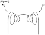
- Figures 2 to 5 are conceptual diagrams showing various embodiments of the heating unit related to the present invention.
- the ink may mean hereby an ink composition that can be thermally fused or thermally cured by induction heating, and the term such as ink or ink composition may be used together in the same sense.
- the 3D printer (1) also comprises a substrate (20) on which the injected ink is deposited and a heating unit (50) provided so as to heat the ink coated onto the substrate (20) through induction heating and to be positioned behind the injection nozzle (40) based on the direction of carriage of the injection nozzle (40).
- the 3D printer (1) also comprises a carriage unit (60) for carrying the injection nozzle (40) and the heating unit (50).
- the 3D printer (1) also comprises a control unit (70) for controlling the heating unit (50) and the carriage unit (50).
- the heating unit (50) is provided to apply an external alternating electromagnetic field to the ink composition (C) deposited on the substrate (20). Specifically, the ink composition (C) can be heated while the induction heating is generated by the electromagnetic field.
- thermosetting resin in the ink composition (C), the thermosetting resin can be cured or the metal particles can be thermally fused, depending on the composition, whereby the three-dimensional printing can proceed.
- the ink injected from the injection nozzle (40) is indicated by the letter I and the ink heated through the heating unit (50) is indicated by the letter C.
- the external alternating electromagnetic field may have a frequency of 100 kHz to 1 GHz and a current of 5 A to 500 A.
- the ink composition can be completely cured within about 10 seconds to 1 hour.
- the heating unit (50) may be provided to form a focused alternating electromagnetic field on the ink composition (C) deposited on the substrate (20).
- the heating unit (50) comprises two coil structures.
- the coil structure may have various structures such as a circular shape, a polygonal shape, and a spiral shape.
- the coil structure can be used for surface heating, inner surface heating, flat plate heating, and the like.
- the shape and number of the coil structure, and the arrangement between the coil structures can be variously determined.
- the coil structure may have a cylindrical shape, a spiral shape, or a pancake shape.
- the coil structure may have a circular or rectangular coil shape.
- the heating unit (50) may be disposed adjacent to the injection nozzle (40).
- the heating unit (50) is also provided to be positioned behind the injection nozzle (40), based on the direction of carriage of the injection nozzle (40). Specifically, as the heating unit (50) is provided at the rear of the direction of carriage of the injection nozzle (40), the injection of the ink through the injection nozzle (40) and the heating of the ink through the heating unit (50) can be performed simultaneously or sequentially.
- the carriage unit (60) may be provided to carry the heating unit (50) and the injection nozzle (40) integrally. At this time, the heating unit (50) and the injection nozzle (40) can be carried at the same speed. Alternatively, the carriage unit (60) may be provided to carry the heating unit (50) and the injection nozzle (40) individually. At this time, the heating unit (50) and the injection nozzle (40) may be provided to be carried at speeds different from each other.
- the carriage unit may comprise a driving source such as a motor and may be constituted by a known element used for carrying the ink nozzle in the printer technology field.
- the carriage unit (60) may be provided to adjust the interval between the substrate (20) and the heating unit (50).
- the heating unit (50) may be provided so as to be movable up and down with respect to the substrate (20).
- the substrate (20) may be provided so as to be movable up and down with respect to the heating unit (50). That is, the carriage unit (60) may be provided to adjust the relative position of the heating unit (50) with respect to the substrate (20), and at least one of the heating unit (50) and the substrate (20) may be provided to be movable up and down.
- the carriage unit (60) may be provided to adjust the interval between the substrate (20) and the injection nozzle (40).
- control unit (70) may be provided to operate the heating unit (50) while applying the ink (I).
- control unit (70) may be provided to operate the heating unit (50) after a predetermined time has elapsed from the application of the ink.
- the heating unit (150) may comprise two coil structures (151, 152) disposed on both sides of the rear, respectively, base on the injection nozzle (40).
- the heating unit (150) may be provided to apply an external alternating electromagnetic field to the ink positioned in the space between the two coil structures (151, 152).
- the heating unit (150) may also be provided so that the center line (L) of the nozzle head in the injection nozzle (40) is located between the two coil structures (151, 152).
- the two coil structures (151, 152) may be provided in the Helmholtz type (see Figure 3 ), the dual pancake type (see Figure 4 ), or the bi-conical type (see Figure 5 ).
- the magnetic particles may comprise metal particles, metal oxides, ferrite, or alloy particles, having ferromagnetism.
- the magnetic particles may comprise magnetic nanoparticles.
- the ink composition (I) may comprise a thermosetting polymer and magnetic nanoparticles.
- a magnetic field is formed in the magnetic nanoparticles, whereby the thermosetting polymer can be cured by the generated heat. Therefore, the ink composition (I) can also be cured only by applying an external alternating electromagnetic field instead of curing by the direct heat.
- the kind of monomers or oligomers in the thermosetting polymer is not particularly limited, but one or more selected from the group consisting of a monomer of an epoxy resin, a monomer of a phenol resin, a monomer of an amino resin, a monomer of an unsaturated polyester resin, a monomer of an acrylic resin, a monomer of a maleimide resin and a monomer of a cyanate resin can be used, and preferably one or more selected from the group consisting of a monomer of an epoxy resin, a monomer of an acrylic resin and a monomer of a maleimide resin can be used.
- the monomer or oligomer of the thermosetting polymer may also be contained in an amount of 80 to 99 parts by weight, relative to the total weight of the ink composition.
- the magnetic nanoparticles have a diameter of 1 to 999 nm, preferably a diameter of 30 to 300 nm, more preferably a diameter of 50 to 100 nm, and still more preferably a diameter of 50 to 60 nm.
- the magnetic nanoparticles may be one or more selected from the group consisting of Fe 3 O 4 , Fe 2 O 3 , MnFe 2 O 4 , CoFe 2 O 4 , Fe, CoPt, and FePt.
- the ink composition (I) may comprise 80 to 99 parts by weight of the thermosetting polymer and 1 to 20 parts by weight of the magnetic nanoparticles, relative to the total weight. If the content of the magnetic nanoparticles is less than 1 part by weight, the time for curing the ink composition becomes longer, and if the content of the magnetic nanoparticles exceeds 20 parts by weight, the color of the cured resin may become much darker due to blackish magnetic nanoparticles. Also, as an aggregation phenomenon of the magnetic nanoparticles may occur, voids in the cured resin may also be caused, whereby cracking may also be caused.
- the ink composition may further comprise one or more selected from the group consisting of a curing agent and a cross-linking agent.
- a curing agent is not particularly limited, but for example, one or more selected from the group consisting of organic peroxides, hydroperoxides, azo compounds, imidazoles, aliphatic amines, aromatic amines, tertiary amines, polyamide resins, phenol resins and acid anhydrides can be used.
- the curing agent may be included in an amount of 1 to 10 parts by weight, and preferably 1 to 5 parts by weight, relative to the total weight of the ink composition.
- the content of the curing agent is less than 1 part by weight, it may take a long time to completely cure the ink composition, and if it is more than 10 parts by weight, a large amount of polymer having a short chain length may be generated to reduce thermal stability of the cured resin.
- the kind of the cross-linking agent is not particularly limited, but for example, one or more selected from the group consisting of phenol novolac resins, phenol alkyl resins, allylated phenol novolac resins and microcapsule type cross-linking agent can be used.
- the cross-linking agent By further using the cross-linking agent, hardness and thermal stability of the ink composition can be increased.
- the cross-linking agent may be included in an amount of 1 to 10 parts by weight, relative to the total weight of the ink composition, where if the content of the cross-linking agent is less than 1 part by weight, cross-linking is not sufficiently carried out and thus the polymer may be melted at a high temperature and flow, and expansion due to the solvent may occur, and if it is more than 10 parts by weight, cross-linking is excessively large and thus the cured resin may be in a fragile state.
- the injection nozzle (40) connected to the ink tank (10) and the heating unit (50) for applying an external alternating electromagnetic field to the ink composition so as to form thermal curing can constitute the printer head (30).
- the above-described carriage unit (60) adjusts the relative position of the printer head (30) with respect to the substrate (20).
- control unit (70) is provided to control the carriage unit (60) and the print head (30). Also, the control unit (70) can control to form the injection of the ink composition (I) and the generation of the external alternating electromagnetic field simultaneously.
- the carriage unit (60) may be configured as a conventional carriage unit for carrying the nozzle head from the printer.
- the carriage unit (60) may comprise a rail part according to the injection trajectory and one or more motors for moving the printer head (30) on the rail part.
- the carriage unit (60) may comprise one or more motors (e.g., step motors) for raising and lowering the printer head (30) and/or the substrate (20).
- the ink composition related to the present invention may comprise micro-sized metal particles and additives (for example, organic components).
- the metal particles are thermally fused through induction heating, so that the 3D printing may proceed.
- the ink composition may also comprise a thermosetting resin and magnetic nanoparticles (thermosetting resin ink), or may also comprise metal particles and additives (metallic ink).
- thermosetting resin ink the thermosetting polymer is included as the main component, based on the total weight of the ink composition, and the magnetic nanoparticles are included as the auxiliary component, whereas in the case of the metallic ink, micro-sized metal particles are included as the main component.
- the metallic ink it is possible to remove additive components through the process of thermally fusing metal particles via induction heating.
- the magnetic particles may comprise metal oxide, ferrite or alloy particles.
- the metal oxide may also comprise one or more oxides selected from the group consisting of iron (Fe), cobalt (Co), nickel (Ni), chromium (Cr), yttrium (Y), samarium (Sm) and gadolinium (Gd).
- the ferrite comprises MO ⁇ Fe 2 O 3 , where M may be a divalent metal ion.
- the divalent metal ion may comprise manganese, iron, cobalt, nickel or zinc.
- the alloy particles may comprise FePt, CoPt, Ni-Zn or Mn-Zn.
- the ink may comprise ceramic particles.
- the ceramic may comprise one or more oxides, nitrides, or carbides selected from the group consisting of silicon (Si), aluminum (Al), titanium (Ti) and zirconium (Zr).
- the ink may comprise inorganic particles and ceramic particles, having a core-shell structure.
- the shell may comprise ceramic.
- the core may comprise magnetic particles or a metal powder and the core may comprise one or more oxides selected from the group consisting of iron (Fe), cobalt (Co), nickel (Ni), chromium (Cr), yttrium (Y), samarium (Sm) and gadolinium (Gd).
- the composition may comprise a ceramic sol solvent.
- the composition may be a ceramic sol solution.
- the uniform thermal curing can be performed by generating heat from the magnetic particles or the metal powder uniformly dispersed in the composition, and the strength of the finally cured product can be increased by accompanying the curing of the ceramic particles together with the curing of the ceramic sol.
- the curing may be performed by sintering between the ceramic materials, without being limited thereto, and the curing of the composition may proceed with the curable resin as described below.
- the 3D printer related to the present invention is capable of generating thermal curing or thermal fusion of an ink (or ink composition) through induction heating and is provided so as to be capable of forming a focused alternating electromagnetic field in a region on which the ink is applied.
Landscapes
- Chemical & Material Sciences (AREA)
- Engineering & Computer Science (AREA)
- Materials Engineering (AREA)
- Manufacturing & Machinery (AREA)
- Physics & Mathematics (AREA)
- Mechanical Engineering (AREA)
- Optics & Photonics (AREA)
- Ceramic Engineering (AREA)
- Civil Engineering (AREA)
- Composite Materials (AREA)
- Structural Engineering (AREA)
Claims (13)
- Une imprimante 3D (1) comportant un réservoir à encre (10) conçu pour la conservation d'une encre (I) contenant des particules magnétiques
une buse d'injection (40) raccordée au réservoir à encre (10) et conçue pour injecter de l'encre (I)
une surface de base (20) sur laquelle se dépose l'encre (I) injectée et
un bloc de chauffage (50) qui a pour but de réchauffer l'encre (I) qui recouvre la surface de base (20), par l'entremise d'un dispositif de chauffage par induction qui vient se positionner derrière la buse d'injection (40), en fonction du sens de déplacement du plateau de la buse d'injection (40)
un bloc plateau (60) conçu pour soutenir la buse d'injection (40) et le bloc de chauffage (50) et
un bloc de commande (70) conçu pour réguler le bloc de chauffage (50) et le bloc plateau (60)
et le bloc de chauffage (50) comporte deux structures à serpentins (151, 152) implantées sur les deux côtés, en position postérieure par rapport à la buse d'injection (40) et
ce bloc de chauffage (50) est conçu pour appliquer un champ électromagnétique alternatif sur l'encre (I) et vient se positionner dans l'espace qui se situe entre les deux structures à serpentins (151, 152). - L'imprimante 3D que décrit la revendication 1, si ce n'est que :
le bloc de chauffage (50) est conçu pour appliquer un champ électromagnétique alternatif externe à l'encre (I) qui se dépose sur la surface de base (20). - L'imprimante 3D que décrit la revendication 2, si ce n'est que :
le bloc de chauffage (50) est conçu pour former un champ électromagnétique alternatif qui se concentre sur l'encre (I) qui se dépose sur la surface de base (20). - L'imprimante 3D que décrit la revendication 1, si ce n'est que :
la structure à serpentins (151, 152) a un profil cylindrique, un profil en spirale ou un profil en forme de crêpe. - L'imprimante 3D que décrit la revendication 1, si ce n'est que :
la structure à serpentins (151, 152) a un profil à serpentins circulaires ou rectangulaires. - L'imprimante 3D que décrit la revendication 1, si ce n'est que :
le groupe de chauffage (50) qui est fourni est conçu a une tête de buse dont l'axe central, dans la buse d'injection (40), vient se positionner entre les deux structures à serpentins (151, 152). - L'imprimante 3D que décrit la revendication 1, si ce n'est que :
les deux structures à serpentins (151, 152) qui sont fournies sont de type Helmholtz, de type biconique ou de type à double profil en forme de crêpes. - L'imprimante 3D que décrit l'une ou l'autre des revendications 1 à 7, si ce n'est que :
le bloc plateau (60) qui est fourni est conçu pour soutenir, de manière intégrale, le groupe de chauffage (50) et la buse d'injection (40). - L'imprimante 3D que décrit l'une ou l'autre des revendications 1 à 8, si ce n'est que :
le bloc plateau (60) qui est fourni est conçu pour soutenir, individuellement, le bloc de chauffage (50) et la buse d'injection (40). - L'imprimante 3D que décrit la revendication 9, si ce n'est que :
le bloc plateau (60) qui est fourni est conçu pour soutenir le bloc de chauffage (50) et la buse d'injection (40) à des vitesses différentes l'un de l'autre. - L'imprimante 3D que décrit l'une ou l'autre des revendications 1 à 10, si ce n'est que :
le bloc plateau (60) qui est fourni est conçu pour ajuster la position relative du bloc de chauffage (50) par rapport à celle de la surface de base (20). - L'imprimante 3D que décrit la revendication 11, si ce n'est qu'au moins :
un bloc de chauffage (50) et la surface de base (20) sont fournis pour pouvoir se déplacer vers le haut et vers le bas. - L'imprimante 3D que décrit l'une ou l'autre des revendications 1 à 12, si ce n'est que :
le bloc plateau (60) qui est fourni est conçu pour ajuster l'intervalle entre la surface de base (20) et la buse d'injection (40).
Applications Claiming Priority (2)
| Application Number | Priority Date | Filing Date | Title |
|---|---|---|---|
| KR20150063861 | 2015-05-07 | ||
| PCT/KR2016/004790 WO2016178545A1 (fr) | 2015-05-07 | 2016-05-09 | Imprimante 3d |
Publications (3)
| Publication Number | Publication Date |
|---|---|
| EP3292990A1 EP3292990A1 (fr) | 2018-03-14 |
| EP3292990A4 EP3292990A4 (fr) | 2019-03-27 |
| EP3292990B1 true EP3292990B1 (fr) | 2021-08-11 |
Family
ID=57540601
Family Applications (1)
| Application Number | Title | Priority Date | Filing Date |
|---|---|---|---|
| EP16789651.3A Active EP3292990B1 (fr) | 2015-05-07 | 2016-05-09 | Imprimante 3d |
Country Status (5)
| Country | Link |
|---|---|
| US (1) | US10974455B2 (fr) |
| EP (1) | EP3292990B1 (fr) |
| JP (1) | JP6554740B2 (fr) |
| KR (1) | KR101819335B1 (fr) |
| CN (1) | CN107614244B (fr) |
Families Citing this family (21)
| Publication number | Priority date | Publication date | Assignee | Title |
|---|---|---|---|---|
| EP3354684B1 (fr) * | 2015-09-25 | 2021-11-17 | LG Chem, Ltd. | Composition pour impression 3d |
| WO2017052337A1 (fr) * | 2015-09-25 | 2017-03-30 | 주식회사 엘지화학 | Composition pour impression 3d |
| EP3536740A4 (fr) | 2016-11-04 | 2019-11-13 | LG Chem, Ltd. | Composition thermodurcissable |
| KR102089406B1 (ko) * | 2017-04-26 | 2020-03-16 | 주식회사 엘지화학 | 노즐 조립체 및 이를 포함하는 3d 프린터 |
| KR102171282B1 (ko) * | 2017-04-26 | 2020-10-28 | 주식회사 엘지화학 | 노즐 조립체 및 이를 포함하는 3d 프린터 |
| US11101532B2 (en) * | 2017-04-28 | 2021-08-24 | 3D Glass Solutions, Inc. | RF circulator |
| KR102152465B1 (ko) * | 2018-10-10 | 2020-09-07 | 한국기계연구원 | 3d 프린팅 시스템 분말제어 장치 및 방법 |
| CN109333999B (zh) * | 2018-11-20 | 2023-12-29 | 青岛科技大学 | 一种热固性聚合物增材制造装置及方法 |
| JP7204276B2 (ja) | 2018-12-06 | 2023-01-16 | エルジー・ケム・リミテッド | 吐出装置、成形装置、及び成形体の製造方法 |
| CN109483869B (zh) * | 2018-12-12 | 2020-10-20 | 哈尔滨工业大学 | 一种用于热固性形状记忆聚合物在轨4d打印的装置 |
| JP7321624B2 (ja) * | 2018-12-25 | 2023-08-07 | エルジー・ケム・リミテッド | 成形装置及び成形体の製造方法 |
| US20220289935A1 (en) * | 2019-07-11 | 2022-09-15 | Lg Chem, Ltd. | Resin-Filled Material, and the Manufacturing Method Thereof |
| JP7367358B2 (ja) * | 2019-07-11 | 2023-10-24 | 大同特殊鋼株式会社 | ボンド磁石製造方法 |
| EP3875185A1 (fr) * | 2020-03-05 | 2021-09-08 | Evonik Operations GmbH | Frittage superparamagnétique sélectif et encre appropriée associée |
| KR102215528B1 (ko) | 2020-04-16 | 2021-02-16 | 주식회사 웨이브피아 | 3d프린터용 rf 가열 장치를 적용한 노즐 구조 |
| EP4094926B1 (fr) * | 2021-05-26 | 2024-01-31 | uppolluX GmbH & Co. KG | Dispositif, système et son utilisation, ainsi que procédé de génération d'une structure 3d |
| KR102570503B1 (ko) * | 2021-08-09 | 2023-08-24 | 한양대학교 산학협력단 | 진동부와 가열부를 구비한 금속 3d 프린터 |
| KR102823445B1 (ko) * | 2023-01-20 | 2025-06-20 | 에이비씨에너지 주식회사 | 3d 프린팅을 이용하여 제조된 산화물 필름 |
| AT527625B1 (de) * | 2023-10-12 | 2026-04-15 | Plasmics Gmbh | Extrusionskopf für die additive Fertigung eines Formkörpers |
| WO2025089876A1 (fr) * | 2023-10-25 | 2025-05-01 | 주식회사 알데바 | Appareil de fabrication de vaisseau sanguin artificiel et procédé de fabrication de vaisseau sanguin artificiel l'utilisant |
| CN120382642A (zh) * | 2025-06-03 | 2025-07-29 | 青岛理工大学 | 三维磁场辅助纳米颗粒增强功能梯度水凝胶快速制造装置 |
Family Cites Families (12)
| Publication number | Priority date | Publication date | Assignee | Title |
|---|---|---|---|---|
| JP2000094530A (ja) | 1998-09-25 | 2000-04-04 | Canon Inc | 造形装置及び造形方法 |
| US6405095B1 (en) * | 1999-05-25 | 2002-06-11 | Nanotek Instruments, Inc. | Rapid prototyping and tooling system |
| US20040151978A1 (en) | 2003-01-30 | 2004-08-05 | Huang Wen C. | Method and apparatus for direct-write of functional materials with a controlled orientation |
| US8437104B2 (en) * | 2006-04-06 | 2013-05-07 | Sigma Pro Ltd. Llc | Read/write apparatus and method for a magnetic storage medium comprised of magnetic nanoparticles contained within nanotubes |
| WO2007114895A2 (fr) | 2006-04-06 | 2007-10-11 | Z Corporation | production d'éléments tridimensionnels au moyen de radiations électromagnétiques |
| JP5113164B2 (ja) | 2007-06-01 | 2013-01-09 | ビ−エイイ− システムズ パブリック リミテッド カンパニ− | ディレクト・ライトおよび付加的製造法に関する改良 |
| EP2182787A1 (fr) | 2008-10-30 | 2010-05-05 | BAE Systems PLC | Améliorations associées à des procédés de fabrication d'additifs |
| JP2013067036A (ja) | 2011-09-21 | 2013-04-18 | Keyence Corp | 3次元造形装置 |
| EP2764935B1 (fr) * | 2013-02-11 | 2017-08-23 | King Abdulaziz City for Science & Technology (KACST) | Procédé de fabrication d'un élément d'une pluralité d'éléments de moulage, procédé de moulage pour fabriquer et système permettant de couler un objet tridimensionnel |
| US20140363326A1 (en) | 2013-06-10 | 2014-12-11 | Grid Logic Incorporated | System and method for additive manufacturing |
| JP2015000476A (ja) | 2013-06-13 | 2015-01-05 | コニカミノルタ株式会社 | 三次元造形方法及び三次元造形装置 |
| EP3266815B1 (fr) * | 2013-11-05 | 2021-11-03 | Covestro (Netherlands) B.V. | Compositions stabilisées de résine durcissables par rayonnement liquide de matrice chargée pour fabrication additive |
-
2016
- 2016-05-09 EP EP16789651.3A patent/EP3292990B1/fr active Active
- 2016-05-09 JP JP2017554556A patent/JP6554740B2/ja active Active
- 2016-05-09 CN CN201680025954.5A patent/CN107614244B/zh active Active
- 2016-05-09 US US15/569,942 patent/US10974455B2/en active Active
- 2016-05-09 KR KR1020160056080A patent/KR101819335B1/ko active Active
Also Published As
| Publication number | Publication date |
|---|---|
| JP2018515361A (ja) | 2018-06-14 |
| EP3292990A4 (fr) | 2019-03-27 |
| KR20160131954A (ko) | 2016-11-16 |
| CN107614244B (zh) | 2020-01-17 |
| KR101819335B1 (ko) | 2018-01-17 |
| EP3292990A1 (fr) | 2018-03-14 |
| JP6554740B2 (ja) | 2019-08-07 |
| US20180154577A1 (en) | 2018-06-07 |
| CN107614244A (zh) | 2018-01-19 |
| US10974455B2 (en) | 2021-04-13 |
Similar Documents
| Publication | Publication Date | Title |
|---|---|---|
| EP3292990B1 (fr) | Imprimante 3d | |
| CN106796835B (zh) | 具有不同磁性质的区域的磁体以及用于形成这种磁体的方法 | |
| CN108136497B (zh) | 用于3d打印的组合物 | |
| JP5994382B2 (ja) | 樹脂成形体およびその製造方法 | |
| JP6073087B2 (ja) | 繊維強化部品のダイレクトデジタル製造のための方法、装置、及び材料混合物 | |
| EP3412715B1 (fr) | Composition pour impression 3d | |
| US10124531B2 (en) | Rapid non-contact energy transfer for additive manufacturing driven high intensity electromagnetic fields | |
| CN104269265B (zh) | 磁场取向三维打印各向异性粘结磁体及其制备方法 | |
| WO2016178545A1 (fr) | Imprimante 3d | |
| US12106892B2 (en) | Method for three-dimensional printing of magnetic materials | |
| EP3711949A1 (fr) | Procédé et appareil de fabrication d'une structure magnétique | |
| KR102041811B1 (ko) | 3d 프린팅용 조성물 | |
| Bastola et al. | Drop-on-demand 3D printing of programable magnetic composites for soft robotics | |
| KR20210116232A (ko) | 3d 인쇄된 물체의 z-축 강도를 개선하기 위한 자성 입자의 이용 | |
| JP2016189462A (ja) | 異方性ボンド磁石の製造方法及び製造装置並びに異方性ボンド磁石 | |
| CN109983063A (zh) | 热固性组合物 | |
| US20220388241A1 (en) | Use of Multi-Axis Magnetic fields in Orienting Material Property Enhancing Fibers, including for Strengthening and Joining purposes, in Additive Manufacturing Processes | |
| CN110573322B (zh) | 喷嘴组合件和包括其的3d打印机 | |
| JP2017075369A (ja) | 三次元造形物の製造方法及び三次元造形物の製造装置 | |
| JP5114126B2 (ja) | 磁気シール部材及びその製造方法 | |
| KR20230080905A (ko) | 노즐 조립체와, 이를 포함하는 3차원 프린터 및 3차원 프린팅 방법, 이를 이용하여 제조되는 전자 부품 케이스 | |
| KR102354937B1 (ko) | 조성물 | |
| US20250269597A1 (en) | Electromagnetic sensitive epoxy/resin system for additive manufacturing applications | |
| CN113665099A (zh) | 通过熔丝制造生产部件的方法和用于生产部件的装置 |
Legal Events
| Date | Code | Title | Description |
|---|---|---|---|
| STAA | Information on the status of an ep patent application or granted ep patent |
Free format text: STATUS: THE INTERNATIONAL PUBLICATION HAS BEEN MADE |
|
| PUAI | Public reference made under article 153(3) epc to a published international application that has entered the european phase |
Free format text: ORIGINAL CODE: 0009012 |
|
| STAA | Information on the status of an ep patent application or granted ep patent |
Free format text: STATUS: REQUEST FOR EXAMINATION WAS MADE |
|
| 17P | Request for examination filed |
Effective date: 20171102 |
|
| AK | Designated contracting states |
Kind code of ref document: A1 Designated state(s): AL AT BE BG CH CY CZ DE DK EE ES FI FR GB GR HR HU IE IS IT LI LT LU LV MC MK MT NL NO PL PT RO RS SE SI SK SM TR |
|
| AX | Request for extension of the european patent |
Extension state: BA ME |
|
| DAV | Request for validation of the european patent (deleted) | ||
| DAX | Request for extension of the european patent (deleted) | ||
| A4 | Supplementary search report drawn up and despatched |
Effective date: 20190221 |
|
| RIC1 | Information provided on ipc code assigned before grant |
Ipc: B33Y 30/00 20150101ALI20190215BHEP Ipc: B29K 505/00 20060101ALN20190215BHEP Ipc: B29C 64/393 20170101ALI20190215BHEP Ipc: B29C 64/112 20170101ALI20190215BHEP Ipc: B29C 64/295 20170101AFI20190215BHEP Ipc: B29K 509/02 20060101ALN20190215BHEP Ipc: B33Y 50/02 20150101ALI20190215BHEP Ipc: B33Y 70/00 20150101ALI20190215BHEP Ipc: B33Y 40/00 20150101ALI20190215BHEP |
|
| RIC1 | Information provided on ipc code assigned before grant |
Ipc: B33Y 30/00 20150101ALI20210303BHEP Ipc: B33Y 50/02 20150101ALI20210303BHEP Ipc: B33Y 70/00 20200101ALI20210303BHEP Ipc: B29C 64/393 20170101ALI20210303BHEP Ipc: B29C 64/112 20170101ALI20210303BHEP Ipc: B33Y 40/00 20200101ALI20210303BHEP Ipc: B29C 64/295 20170101AFI20210303BHEP Ipc: B29K 505/00 20060101ALN20210303BHEP Ipc: B29K 509/02 20060101ALN20210303BHEP |
|
| REG | Reference to a national code |
Ref country code: DE Ref legal event code: R079 Ref document number: 602016062075 Country of ref document: DE Free format text: PREVIOUS MAIN CLASS: B29C0067000000 Ipc: B29C0064295000 |
|
| RIC1 | Information provided on ipc code assigned before grant |
Ipc: B29K 509/02 20060101ALN20210309BHEP Ipc: B29K 505/00 20060101ALN20210309BHEP Ipc: B29C 64/393 20170101ALI20210309BHEP Ipc: B33Y 50/02 20150101ALI20210309BHEP Ipc: B33Y 40/00 20200101ALI20210309BHEP Ipc: B33Y 30/00 20150101ALI20210309BHEP Ipc: B33Y 70/00 20200101ALI20210309BHEP Ipc: B29C 64/112 20170101ALI20210309BHEP Ipc: B29C 64/295 20170101AFI20210309BHEP |
|
| GRAP | Despatch of communication of intention to grant a patent |
Free format text: ORIGINAL CODE: EPIDOSNIGR1 |
|
| STAA | Information on the status of an ep patent application or granted ep patent |
Free format text: STATUS: GRANT OF PATENT IS INTENDED |
|
| RIC1 | Information provided on ipc code assigned before grant |
Ipc: B29C 35/08 20060101ALN20210401BHEP Ipc: B29K 509/02 20060101ALN20210401BHEP Ipc: B29K 505/00 20060101ALN20210401BHEP Ipc: B29C 64/393 20170101ALI20210401BHEP Ipc: B33Y 50/02 20150101ALI20210401BHEP Ipc: B33Y 40/00 20200101ALI20210401BHEP Ipc: B33Y 30/00 20150101ALI20210401BHEP Ipc: B33Y 70/00 20200101ALI20210401BHEP Ipc: B29C 64/112 20170101ALI20210401BHEP Ipc: B29C 64/295 20170101AFI20210401BHEP |
|
| RIC1 | Information provided on ipc code assigned before grant |
Ipc: B29C 35/08 20060101ALN20210409BHEP Ipc: B29K 509/02 20060101ALN20210409BHEP Ipc: B29K 505/00 20060101ALN20210409BHEP Ipc: B29C 64/393 20170101ALI20210409BHEP Ipc: B33Y 50/02 20150101ALI20210409BHEP Ipc: B33Y 40/00 20200101ALI20210409BHEP Ipc: B33Y 30/00 20150101ALI20210409BHEP Ipc: B33Y 70/00 20200101ALI20210409BHEP Ipc: B29C 64/112 20170101ALI20210409BHEP Ipc: B29C 64/295 20170101AFI20210409BHEP |
|
| INTG | Intention to grant announced |
Effective date: 20210430 |
|
| GRAS | Grant fee paid |
Free format text: ORIGINAL CODE: EPIDOSNIGR3 |
|
| GRAA | (expected) grant |
Free format text: ORIGINAL CODE: 0009210 |
|
| STAA | Information on the status of an ep patent application or granted ep patent |
Free format text: STATUS: THE PATENT HAS BEEN GRANTED |
|
| AK | Designated contracting states |
Kind code of ref document: B1 Designated state(s): AL AT BE BG CH CY CZ DE DK EE ES FI FR GB GR HR HU IE IS IT LI LT LU LV MC MK MT NL NO PL PT RO RS SE SI SK SM TR |
|
| REG | Reference to a national code |
Ref country code: CH Ref legal event code: EP |
|
| REG | Reference to a national code |
Ref country code: DE Ref legal event code: R096 Ref document number: 602016062075 Country of ref document: DE |
|
| REG | Reference to a national code |
Ref country code: IE Ref legal event code: FG4D Ref country code: AT Ref legal event code: REF Ref document number: 1418945 Country of ref document: AT Kind code of ref document: T Effective date: 20210915 |
|
| REG | Reference to a national code |
Ref country code: LT Ref legal event code: MG9D |
|
| REG | Reference to a national code |
Ref country code: NL Ref legal event code: MP Effective date: 20210811 |
|
| REG | Reference to a national code |
Ref country code: AT Ref legal event code: MK05 Ref document number: 1418945 Country of ref document: AT Kind code of ref document: T Effective date: 20210811 |
|
| PG25 | Lapsed in a contracting state [announced via postgrant information from national office to epo] |
Ref country code: RS Free format text: LAPSE BECAUSE OF FAILURE TO SUBMIT A TRANSLATION OF THE DESCRIPTION OR TO PAY THE FEE WITHIN THE PRESCRIBED TIME-LIMIT Effective date: 20210811 Ref country code: SE Free format text: LAPSE BECAUSE OF FAILURE TO SUBMIT A TRANSLATION OF THE DESCRIPTION OR TO PAY THE FEE WITHIN THE PRESCRIBED TIME-LIMIT Effective date: 20210811 Ref country code: NO Free format text: LAPSE BECAUSE OF FAILURE TO SUBMIT A TRANSLATION OF THE DESCRIPTION OR TO PAY THE FEE WITHIN THE PRESCRIBED TIME-LIMIT Effective date: 20211111 Ref country code: PT Free format text: LAPSE BECAUSE OF FAILURE TO SUBMIT A TRANSLATION OF THE DESCRIPTION OR TO PAY THE FEE WITHIN THE PRESCRIBED TIME-LIMIT Effective date: 20211213 Ref country code: HR Free format text: LAPSE BECAUSE OF FAILURE TO SUBMIT A TRANSLATION OF THE DESCRIPTION OR TO PAY THE FEE WITHIN THE PRESCRIBED TIME-LIMIT Effective date: 20210811 Ref country code: ES Free format text: LAPSE BECAUSE OF FAILURE TO SUBMIT A TRANSLATION OF THE DESCRIPTION OR TO PAY THE FEE WITHIN THE PRESCRIBED TIME-LIMIT Effective date: 20210811 Ref country code: FI Free format text: LAPSE BECAUSE OF FAILURE TO SUBMIT A TRANSLATION OF THE DESCRIPTION OR TO PAY THE FEE WITHIN THE PRESCRIBED TIME-LIMIT Effective date: 20210811 Ref country code: LT Free format text: LAPSE BECAUSE OF FAILURE TO SUBMIT A TRANSLATION OF THE DESCRIPTION OR TO PAY THE FEE WITHIN THE PRESCRIBED TIME-LIMIT Effective date: 20210811 Ref country code: BG Free format text: LAPSE BECAUSE OF FAILURE TO SUBMIT A TRANSLATION OF THE DESCRIPTION OR TO PAY THE FEE WITHIN THE PRESCRIBED TIME-LIMIT Effective date: 20211111 Ref country code: AT Free format text: LAPSE BECAUSE OF FAILURE TO SUBMIT A TRANSLATION OF THE DESCRIPTION OR TO PAY THE FEE WITHIN THE PRESCRIBED TIME-LIMIT Effective date: 20210811 |
|
| PG25 | Lapsed in a contracting state [announced via postgrant information from national office to epo] |
Ref country code: PL Free format text: LAPSE BECAUSE OF FAILURE TO SUBMIT A TRANSLATION OF THE DESCRIPTION OR TO PAY THE FEE WITHIN THE PRESCRIBED TIME-LIMIT Effective date: 20210811 Ref country code: LV Free format text: LAPSE BECAUSE OF FAILURE TO SUBMIT A TRANSLATION OF THE DESCRIPTION OR TO PAY THE FEE WITHIN THE PRESCRIBED TIME-LIMIT Effective date: 20210811 Ref country code: GR Free format text: LAPSE BECAUSE OF FAILURE TO SUBMIT A TRANSLATION OF THE DESCRIPTION OR TO PAY THE FEE WITHIN THE PRESCRIBED TIME-LIMIT Effective date: 20211112 |
|
| PG25 | Lapsed in a contracting state [announced via postgrant information from national office to epo] |
Ref country code: NL Free format text: LAPSE BECAUSE OF FAILURE TO SUBMIT A TRANSLATION OF THE DESCRIPTION OR TO PAY THE FEE WITHIN THE PRESCRIBED TIME-LIMIT Effective date: 20210811 |
|
| PG25 | Lapsed in a contracting state [announced via postgrant information from national office to epo] |
Ref country code: DK Free format text: LAPSE BECAUSE OF FAILURE TO SUBMIT A TRANSLATION OF THE DESCRIPTION OR TO PAY THE FEE WITHIN THE PRESCRIBED TIME-LIMIT Effective date: 20210811 |
|
| REG | Reference to a national code |
Ref country code: DE Ref legal event code: R097 Ref document number: 602016062075 Country of ref document: DE |
|
| PG25 | Lapsed in a contracting state [announced via postgrant information from national office to epo] |
Ref country code: SM Free format text: LAPSE BECAUSE OF FAILURE TO SUBMIT A TRANSLATION OF THE DESCRIPTION OR TO PAY THE FEE WITHIN THE PRESCRIBED TIME-LIMIT Effective date: 20210811 Ref country code: SK Free format text: LAPSE BECAUSE OF FAILURE TO SUBMIT A TRANSLATION OF THE DESCRIPTION OR TO PAY THE FEE WITHIN THE PRESCRIBED TIME-LIMIT Effective date: 20210811 Ref country code: RO Free format text: LAPSE BECAUSE OF FAILURE TO SUBMIT A TRANSLATION OF THE DESCRIPTION OR TO PAY THE FEE WITHIN THE PRESCRIBED TIME-LIMIT Effective date: 20210811 Ref country code: EE Free format text: LAPSE BECAUSE OF FAILURE TO SUBMIT A TRANSLATION OF THE DESCRIPTION OR TO PAY THE FEE WITHIN THE PRESCRIBED TIME-LIMIT Effective date: 20210811 Ref country code: CZ Free format text: LAPSE BECAUSE OF FAILURE TO SUBMIT A TRANSLATION OF THE DESCRIPTION OR TO PAY THE FEE WITHIN THE PRESCRIBED TIME-LIMIT Effective date: 20210811 Ref country code: AL Free format text: LAPSE BECAUSE OF FAILURE TO SUBMIT A TRANSLATION OF THE DESCRIPTION OR TO PAY THE FEE WITHIN THE PRESCRIBED TIME-LIMIT Effective date: 20210811 |
|
| PLBE | No opposition filed within time limit |
Free format text: ORIGINAL CODE: 0009261 |
|
| STAA | Information on the status of an ep patent application or granted ep patent |
Free format text: STATUS: NO OPPOSITION FILED WITHIN TIME LIMIT |
|
| 26N | No opposition filed |
Effective date: 20220512 |
|
| PG25 | Lapsed in a contracting state [announced via postgrant information from national office to epo] |
Ref country code: IT Free format text: LAPSE BECAUSE OF FAILURE TO SUBMIT A TRANSLATION OF THE DESCRIPTION OR TO PAY THE FEE WITHIN THE PRESCRIBED TIME-LIMIT Effective date: 20210811 |
|
| PG25 | Lapsed in a contracting state [announced via postgrant information from national office to epo] |
Ref country code: SI Free format text: LAPSE BECAUSE OF FAILURE TO SUBMIT A TRANSLATION OF THE DESCRIPTION OR TO PAY THE FEE WITHIN THE PRESCRIBED TIME-LIMIT Effective date: 20210811 |
|
| REG | Reference to a national code |
Ref country code: CH Ref legal event code: PL |
|
| REG | Reference to a national code |
Ref country code: BE Ref legal event code: MM Effective date: 20220531 |
|
| PG25 | Lapsed in a contracting state [announced via postgrant information from national office to epo] |
Ref country code: MC Free format text: LAPSE BECAUSE OF FAILURE TO SUBMIT A TRANSLATION OF THE DESCRIPTION OR TO PAY THE FEE WITHIN THE PRESCRIBED TIME-LIMIT Effective date: 20210811 Ref country code: LU Free format text: LAPSE BECAUSE OF NON-PAYMENT OF DUE FEES Effective date: 20220509 Ref country code: LI Free format text: LAPSE BECAUSE OF NON-PAYMENT OF DUE FEES Effective date: 20220531 Ref country code: CH Free format text: LAPSE BECAUSE OF NON-PAYMENT OF DUE FEES Effective date: 20220531 |
|
| PG25 | Lapsed in a contracting state [announced via postgrant information from national office to epo] |
Ref country code: IE Free format text: LAPSE BECAUSE OF NON-PAYMENT OF DUE FEES Effective date: 20220509 |
|
| PG25 | Lapsed in a contracting state [announced via postgrant information from national office to epo] |
Ref country code: BE Free format text: LAPSE BECAUSE OF NON-PAYMENT OF DUE FEES Effective date: 20220531 |
|
| PG25 | Lapsed in a contracting state [announced via postgrant information from national office to epo] |
Ref country code: HU Free format text: LAPSE BECAUSE OF FAILURE TO SUBMIT A TRANSLATION OF THE DESCRIPTION OR TO PAY THE FEE WITHIN THE PRESCRIBED TIME-LIMIT; INVALID AB INITIO Effective date: 20160509 |
|
| PG25 | Lapsed in a contracting state [announced via postgrant information from national office to epo] |
Ref country code: MK Free format text: LAPSE BECAUSE OF FAILURE TO SUBMIT A TRANSLATION OF THE DESCRIPTION OR TO PAY THE FEE WITHIN THE PRESCRIBED TIME-LIMIT Effective date: 20210811 Ref country code: CY Free format text: LAPSE BECAUSE OF FAILURE TO SUBMIT A TRANSLATION OF THE DESCRIPTION OR TO PAY THE FEE WITHIN THE PRESCRIBED TIME-LIMIT Effective date: 20210811 |
|
| PG25 | Lapsed in a contracting state [announced via postgrant information from national office to epo] |
Ref country code: MT Free format text: LAPSE BECAUSE OF FAILURE TO SUBMIT A TRANSLATION OF THE DESCRIPTION OR TO PAY THE FEE WITHIN THE PRESCRIBED TIME-LIMIT Effective date: 20210811 |
|
| PGFP | Annual fee paid to national office [announced via postgrant information from national office to epo] |
Ref country code: DE Payment date: 20250422 Year of fee payment: 10 |
|
| PGFP | Annual fee paid to national office [announced via postgrant information from national office to epo] |
Ref country code: FR Payment date: 20250422 Year of fee payment: 10 |
|
| PG25 | Lapsed in a contracting state [announced via postgrant information from national office to epo] |
Ref country code: TR Free format text: LAPSE BECAUSE OF FAILURE TO SUBMIT A TRANSLATION OF THE DESCRIPTION OR TO PAY THE FEE WITHIN THE PRESCRIBED TIME-LIMIT Effective date: 20210811 |
|
| PGFP | Annual fee paid to national office [announced via postgrant information from national office to epo] |
Ref country code: GB Payment date: 20260324 Year of fee payment: 11 |