EP3296052B1 - Schweissvorrichtung und verfahren zur schweissqualitätsprüfung - Google Patents
Schweissvorrichtung und verfahren zur schweissqualitätsprüfung Download PDFInfo
- Publication number
- EP3296052B1 EP3296052B1 EP16792420.8A EP16792420A EP3296052B1 EP 3296052 B1 EP3296052 B1 EP 3296052B1 EP 16792420 A EP16792420 A EP 16792420A EP 3296052 B1 EP3296052 B1 EP 3296052B1
- Authority
- EP
- European Patent Office
- Prior art keywords
- molten pool
- basis
- weld zone
- welding
- content
- Prior art date
- Legal status (The legal status is an assumption and is not a legal conclusion. Google has not performed a legal analysis and makes no representation as to the accuracy of the status listed.)
- Active
Links
Images


Classifications
-
- B—PERFORMING OPERATIONS; TRANSPORTING
- B23—MACHINE TOOLS; METAL-WORKING NOT OTHERWISE PROVIDED FOR
- B23K—SOLDERING OR UNSOLDERING; WELDING; CLADDING OR PLATING BY SOLDERING OR WELDING; CUTTING BY APPLYING HEAT LOCALLY, e.g. FLAME CUTTING; WORKING BY LASER BEAM
- B23K26/00—Working by laser beam, e.g. welding, cutting or boring
- B23K26/20—Bonding
- B23K26/21—Bonding by welding
- B23K26/211—Bonding by welding with interposition of special material to facilitate connection of the parts
-
- B—PERFORMING OPERATIONS; TRANSPORTING
- B23—MACHINE TOOLS; METAL-WORKING NOT OTHERWISE PROVIDED FOR
- B23K—SOLDERING OR UNSOLDERING; WELDING; CLADDING OR PLATING BY SOLDERING OR WELDING; CUTTING BY APPLYING HEAT LOCALLY, e.g. FLAME CUTTING; WORKING BY LASER BEAM
- B23K26/00—Working by laser beam, e.g. welding, cutting or boring
- B23K26/02—Positioning or observing the workpiece, e.g. with respect to the point of impact; Aligning, aiming or focusing the laser beam
- B23K26/03—Observing, e.g. monitoring, the workpiece
- B23K26/032—Observing, e.g. monitoring, the workpiece using optical means
-
- B—PERFORMING OPERATIONS; TRANSPORTING
- B23—MACHINE TOOLS; METAL-WORKING NOT OTHERWISE PROVIDED FOR
- B23K—SOLDERING OR UNSOLDERING; WELDING; CLADDING OR PLATING BY SOLDERING OR WELDING; CUTTING BY APPLYING HEAT LOCALLY, e.g. FLAME CUTTING; WORKING BY LASER BEAM
- B23K26/00—Working by laser beam, e.g. welding, cutting or boring
- B23K26/20—Bonding
- B23K26/21—Bonding by welding
- B23K26/24—Seam welding
- B23K26/26—Seam welding of rectilinear seams
-
- B—PERFORMING OPERATIONS; TRANSPORTING
- B23—MACHINE TOOLS; METAL-WORKING NOT OTHERWISE PROVIDED FOR
- B23K—SOLDERING OR UNSOLDERING; WELDING; CLADDING OR PLATING BY SOLDERING OR WELDING; CUTTING BY APPLYING HEAT LOCALLY, e.g. FLAME CUTTING; WORKING BY LASER BEAM
- B23K26/00—Working by laser beam, e.g. welding, cutting or boring
- B23K26/70—Auxiliary operations or equipment
- B23K26/702—Auxiliary equipment
Definitions
- the present invention relates to an apparatus for welding and a welding quality inspection method according to the preamble of claims 1 and 5 (see for example DE 10 2010 021596 A1 ).
- Laser welding capable of deep penetration welding can perform welding with higher accuracy and at higher speed than those of conventional arc welding, and has recently grown in use and popularity.
- changes in a depth of penetration and a melt amount and flaws such as cracks and blow holes are generated due to the influence of a surface state and components of a material, workpiece setup accuracy, and the like.
- Patent Document 1 a method of detecting plasma emission generated in a molten pool and monitoring a depth of penetration.
- an apparatus described in Patent Document 1 is aimed to measure a depth of penetration by irradiating a weld zone with an object beam different in a wavelength from a laser beam and causing an optical interferometer to receive the object beam reflected by a bottom of a keyhole.
- Patent Document 2 describes a method of fusion welding wherein material is melted under the supply of external energy to form a molten pool and to be at least partially evaporated and wherein the emission spectrum of excited gas particles is observed and measured.
- Patent Document 3 describes a laser welding method for controlling the magnitude of a molten pool.
- Patent document 4 describes a method of manufacturing a core shroud for a nuclear power plant by laser welding using a weld wire.
- Patent document 5 describes a welding control device capable of utilizing a set of pictures taken at multiple surveillance points directed to a welding zone in order to actively control a welding process.
- Patent Document 1 evaluates the depth of penetration as the welding quality, it is often necessary to evaluate a welding quality other than the depth of penetration depending on members to be welded and a usage. For example, if materials to be welded are austenite stainless steels, a content of a ferrite phase is important for suppressing hot cracking.
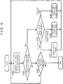
- FIG. 1 is a pattern diagram illustrating an example of a welding apparatus.
- a welding apparatus 100 includes a laser oscillator 1, a laser head 3 that is a light collection optical system, a spectroscopic apparatus 5, a welder control section 8, a filler metal feeder 11, a molten pool observation camera 19, a working table 13, a filler metal feed nozzle 10, a shielding gas nozzle 16, and the like.
- a laser beam generated by the laser oscillator 1 is transferred to the laser head 3 through an optical fiber 2.
- the laser beam 4 collected by the laser head 3 is radiated to workpieces to be welded 17 placed on the working table 13.
- the working table 13 is movable in an x direction and a y direction, and the laser beam 4 can be scanned on the workpieces to be welded 17 by moving the working table 13. It is noted that the laser beam 4 may be scanned by moving the laser head 3 relatively to the working table 13.
- a molten pool 21 is formed on the workpieces to be welded 17 by irradiation of the laser beam 4.
- a filler metal 9 fed from the filler metal feeder 11 is fed to the molten pool 21 through the filler metal feed nozzle 10.
- shielding gas 15 is blown toward the molten pool 21 from the shielding gas nozzle 16.
- the laser oscillator 1, the filler metal feeder 11, and the working table 13 are connected to the welder control section 8 by signal cables 7, 12, and 14, respectively and each operate in response to a signal from the welder control section 8.
- the spectroscopic apparatus 5 and the molten pool observation camera 19 are provided on the laser head 3.
- the laser head 3 is equipped with an optical system that transmits the laser beam from the laser oscillator 1 and that reflects a beam at a wavelength other than a wavelength of the laser beam to the spectroscopic apparatus 5.
- a plasma beam generated in the molten pool 21 is guided to the spectroscopic apparatus 5 coaxially with the laser beam 4 through the laser head 3.
- Spectroscopic information (spectral intensity) about the plasma beam obtained by the spectroscopic apparatus 5 is sent to the welder control section 8 through an optical sensor signal cable 6.
- the molten pool observation camera 19 observes the molten pool 21 coaxially with the laser beam 4.
- Molten pool image information is sent to the welder control section 8 through a molten pool observation camera cable 20.
- 304 austenitic stainless steels with a V-groove formed therebetween are used as the workpieces to be welded 17.
- a 304 austenitic stainless steel higher in a Cr content than a base material is used as the filler metal 9 and a shape thereof is a wire shape. Furthermore, a disk laser beam at a wavelength of about 1030 nm is used as the laser beam 4.
- Nitrogen gas is used as the shielding gas 15. Generally, when the 304 stainless steels are welded together, the nitrogen gas is often used as the shielding gas 15 from the viewpoint of suppression of porosities. This is because the nitrogen gas is absorbed by a weld metal and, therefore, higher suppression of the porosities is possible. However, nitrogen is an austenite stabilizing element.
- the welding apparatus 100 is configured to estimate a property of the weld zone 18 on the basis of the spectroscopic information obtained by the spectroscopic apparatus 5.
- the welder control section 8 can calculate the property of the weld zone 18 (composition of the weld metal) by comparing the spectroscopic information from the spectroscopic apparatus 5 with reference spectroscopic information acquired in advance.
- the filler metal 9 is added to the molten pool 21. Owing to this, the components of the weld zone 18 differ from those of the workpieces to be welded 17 and are useful information to grasp the property and a state of the weld zone 18.
- a ferrite content (percentage of the ferrite phase) in the weld zone 18, that is, the ferrite content in the weld metal depends on a solidification condition including a cooling speed and a temperature gradient as well as the components. Assuming that the solidification condition is generally constant if a welding condition is constant, it is possible to estimate the ferrite content when the components are known. As a method of estimating the ferrite content in the weld metal, there is normally known a method of estimation from a constitution diagram (for example, Schaffler Diagram).
- exponents of austenite forming elements (C, Mn, Ni, and N) are numerically calculated as an Ni equivalent and exponents of ferrite forming elements (Cr, Mo, Si, and Nb) are numerically calculated as a Cr equivalent from the composition of the weld metal obtained by spectroscopic measurement, and the Ni equivalent and the Cr equivalent are applied to the constitution diagram, thereby estimating the ferrite content.
- Such estimation of the ferrite content is performed by the welder control section 8.
- the welder control section 8 There is a correlation between the ferrite content and the hot cracking.
- Fig. 2 illustrates correlation data on the welding under the conditions described above. By holding such correlation data between the ferrite content and the hot cracking in the welder control section 8 in advance, it is possible to estimate the hot cracking by estimation of the ferrite content. According to Fig. 2 , the hot cracking is suppressed with the ferrite content equal to or higher than 3.8%, which indicates that the ferrite content equal to or higher than 3.8% suffices in the laser welding according to the present embodiment.
- the hot cracking is greatly influenced by such trace impurity elements as S (sulfur) and P (phosphorus). Owing to this, by detecting the components of the workpieces to be welded 17 before welding with the present scheme, it is possible to estimate the hot cracking from a relationship between trace elements and the ferrite content. In other words, evaluating a hot cracking susceptibility to S and P contents and the ferrite content enables in-process estimation of the hot cracking with higher accuracy. Furthermore, it may be confirmed whether the weld zone 18 has the composition as set by irradiating the the weld zone 18 with a laser beam after welding.
- the molten pool observation camera 19 is provided to measure the dimension of the molten pool 21 in the present embodiment. While a CCD camera is employed as the molten pool observation camera 19 in the present embodiment, the molten pool observation camera 19 is not limited to this type.
- Fig. 3 is a pattern diagram illustrating an example of the molten pool 21.
- a keyhole 22 is formed at a position of the molten pool 21 at which the molten pool 21 is irradiated with the laser beam 4.
- the laser beam 4 is collected by the light collection system and energy concentrates on a microscopic region (work point). Owing to this, a molten metal at the work point is remarkably evaporated and a recess (hole) is formed in the molten pool 21 by a reaction force thereto. This recess is referred to as "keyhole.”
- a welding direction is a direction indicated by an arrow (upward direction in Fig. 3 ).
- Reference character L1 denotes a width dimension of the molten pool 21, and reference character L2 denotes a length dimension of the molten pool 21.
- the welder control section 8 calculates the width dimension L1 and a length dimension L2 of the molten pool 21 from the molten pool image information by the molten pool observation camera 19.
- a dimension of the weld zone 18 can be estimated from the width dimension L1 and the length dimension L2 of the molten pool 21.
- a storage section (not shown) of the welder control section 8 stores ranges of the width dimension and the length dimension of the molten pool 21 for sound welding in advance.
- the welder control section 8 calculates the dimensions L1 and L2 of the molten pool 21 from the molten pool image information by the molten pool observation camera 19 and compares the dimensions L1 and L2 with the dimension ranges in a case of the sound welding, thereby making it possible to evaluate a failure/no-failure (soundness) of the weld zone 18.
- the width dimension L1 and the length dimension L2 are adopted as indexes of the magnitude of the range of the molten pool 21 herein.
- an area of the molten pool 21, for example, may be estimated from the molten pool image information and the soundness of the weld zone 18 may be evaluated from a magnitude of the area.
- laser power, a welding speed (laser beam scanning speed), and a feed rate of the filler metal are sequentially controlled on the basis of the obtained information on the ferrite content and the obtained molten pool dimension, thereby making it possible to optimize the ferrite content and the molten pool dimension.
- Fig. 4 is a chart illustrating a control flow for keeping optimum the ferrite content and the molten pool dimension.
- This control process is executed by the welder control section 8 and is started by starting welding.
- the welder control section 8 estimates according to the present invention the ferrite content and the dimensions L1 and L2 of the molten pool 21 on the basis of the spectroscopic information on the plasma beam and the molten pool image information on the molten pool 21.
- Step S20 the welder control section 8 determines whether the ferrite content and the dimensions L1 and L2 estimated in Step S10 are each within standard ranges.
- Step S30 the welder control section 8 determines whether a welding end signal has been received, and the welder control section 8 returns to Step S10 when the signal has not been received. On the other hand, when the welding end signal has been received, the welder control section 8 ends a series of processes.
- the welder control section 8 determines whether the no-standard (error) element is only the ferrite content, only the dimension, or both the ferrite content and the dimension. In other words, the welder control section 8 classifies an error into any of a ferrite content error, a dimension error, and ferrite content and dimension errors, and adjusts the welding condition in response to each of the errors.
- the welder control section 8 proceeds to Step S24 and adjusts a feed rate of a wire of the filler metal 9 by a predetermined rate.
- the 304 austenitic stainless steel higher in the Cr content than the base material is used as the filler metal 9, so that the ferrite content increases when the feed rate of the wire is increased, and the ferrite content decreases when the feed rate of the wire is reduced.
- the welder control section 8 adjusts either the laser power or the welding speed (scan speed of the laser beam 4) by a predetermined level, thereby adjusting the dimensions L1 and L2 of the molten pool 21.
- the dimensions L1 and L2 are reduced by reducing the laser power or increasing the welding speed.
- the dimensions L1 and L2 are increased by increasing the laser power or reducing the welding speed.
- the laser power or the welding speed is adjusted first by the predetermined level and the dimensions L1 and L2 of the molten pool 21 are adjusted.
- the feed rate of the wire is then adjusted by a predetermined rate in order to adjust the ferrite content.
- Step S10 the welder control section 8 determines whether the ferrite content and the dimensions L1 and L2 are each within the standard ranges. When there is an error in either the ferrite content or the dimensions L1 and L2, the welder control section 8 proceeds again to Step S22 to perform an adjustment process. On the other hand, when the error is solved by the adjustment, the welder control section 8 proceeds to Step S30.
- the welder control section 8 operates by a mechanism of repeating feedback control over the welding condition according to error classification.
- PID control is used as the feedback control
- the ranges of the ferrite content and the molten pool dimension are set in advance to achieve desired welding, and the feedback control is exercised in such a manner that the ferrite content and the molten pool dimension are within the ranges.
- the PID control is used as the feedback control
- a control method is not limited to the PID control.
- the disk laser beam is used as the laser beam 4
- the laser beam 4 is not limited to the disk laser beam.
- the welding apparatus 100 includes: the laser head 3 that emits the laser beam 4; the spectroscopic apparatus 5 that receives the plasma emission from the molten pool 21 formed by laser beam irradiation, and acquires the optical spectral information; and the welder control section 8 that estimates material components of the weld zone 18 on the basis of the optical spectral information, and estimates the property of the weld zone 18 on the basis of the material components.
- the austenitic stainless steels that are the workpieces to be welded 17 are welded together while feeding the filler metal, then the ferrite content in the weld metal is estimated on the basis of the optical spectral information, and the hot cracking property (see Fig.
- the property of the weld zone 18 is estimated on the basis of the ferrite content. Since the property of the weld zone 18 is estimated on the basis of the optical spectral information as described above, it is possible to determine a failure/non-failure of the property of the weld zone 18 and appropriately manage the property of the weld zone 18 in an in-process manner.
- Patent Document 1 While the conventional welding apparatus described in Patent Document 1 measures the depth of penetration (depth of the keyhole) using the interferometer, the conventional welding apparatus does not estimate the property (hot cracking property) of the weld zone on the basis of the spectroscopic information differently from the present embodiment. It is noted that Patent Document 1 describes estimating the material of the weld zone by measuring the plasma beam by a spectroscope. Nonetheless, this estimation information is used for appropriately controlling the depth of penetration and not for estimating the property of the welded zone differently from the present embodiment. Owing to this, the conventional welding apparatus is unable to evaluate the quality of the weld zone in a many-faceted manner differently from the present embodiment.
- the welding apparatus may further include the molten pool observation camera 19 as a measuring section that measures the magnitude of the molten pool 21 (for example, the dimensions L1 and L2 of Fig. 3 ) in the weld zone 18.
- the welding apparatus further estimates the soundness of the weld zone 18 by determining whether the dimensions L1 and L2 of the molten pool 21 are within the dimension ranges within which the welded state can be determined as being sound, in addition to estimation of the property of the weld zone 18 based on the optical spectral information.
- the welding apparatus can predict the hot cracking property of the weld zone with higher accuracy by referring to the dimensions L1 and L2 of the molten pool 21 for the optical spectral information.
- the hot cracking tends to occur since a higher thermal stress is generated during solidification.
- Combining the optical spectral information with the dimension of the molten pool 21 makes it possible to estimate the property of the weld zone 18 with higher accuracy.
- the feed rate of the filler metal and either the laser power or the laser beam scanning speed during the laser welding may be controlled in such a manner that the magnitude of the molten pool 21 and the ferrite content are each within the predetermined set ranges.
- the preceding has been described while referring to a case of estimating the ferrite content during welding of 304 austenitic stainless steels by way of example.
- a case in which the present invention is applied to dissimilar metal welding will be described.
- a case in which pure Cu and pure Al are welded together will be described hereinafter.
- the workpieces to be welded are not limited to a combination of pure Cu and pure Al but may be a combination of any of, for example, copper or copper alloy, aluminum or aluminum alloy, a steel material, nickel or nickel alloy, cobalt or cobalt alloy, and chromium or chromium alloy.
- a configuration of a welding apparatus is similar to that shown in Fig. 1 and description thereof is omitted herein. It is noted, however, that the filler metal is not used and lap welding is carried out such that an Al material is disposed on an upper side. In the dissimilar metal welding using a Cu material and the Al material, a very brittle intermetallic compound is formed in a weld zone and the compound causes reduction in a joint strength. It is, therefore, necessary to control an amount of the intermetallic compound. To address the challenge, a welding test is conducted while changing welding conditions, a relationship between a dilution rate and the joint strength of the weld zone is acquired in advance, and the relationship is stored in the storage section of the welder control section 8.
- Fig. 5 is a chart illustrating the relationship between the dilution rate and the joint strength.
- a horizontal axis represents the dilution rate (%) indicating a Cu ratio in the molten pool 21.
- This dilution rate is estimated on the basis of the spectroscopic information obtained by the spectroscopic apparatus 5.
- the relationship between an intensity of an optical spectrum corresponding to Cu and the dilution rate (that is, the relationship shown in Fig. 5 ) is stored in the welder control section 8 in advance as reference spectroscopic information.
- the welder control section 8 compares a measured intensity of the optical spectrum corresponding to Cu with the reference spectroscopic information and estimates the dilution rate.
- the joint strength is reduced when a content of Cu mixed into the weld metal increases and the joint strength is greatly reduced when the dilution rate is equal to or higher than about 5%.
- a strength of the weld zone 18 (that is, property of the weld zone 18) can be estimated from a resultant estimated value and the relationship shown in Fig. 5 .
- the soundness of the weld zone 18 can be estimated by determining the dimensions L1 and L2 of the molten pool 21 from the image information by the molten pool observation camera 19 and comparing those dimensions with standard dimensions (dimension ranges for the sound welding).
- Fig. 6 is a chart illustrating a feedback control flow for keeping optimum the dilution rate and the molten pool dimension.
- the welder control section 8 stores a management standard value of the dilution rate and the molten pool dimension ranges in advance. For example, the dilution rate of 5% is stored as the management standard value from data of Fig. 5 .
- the filler metal is not used in the present case. Owing to this, adjustment of the dilution rate is implemented by adjusting the laser power.
- Step S110 the welder control section 8 estimates according to the present invention the dilution rate and the dimensions L1 and L2 of the molten pool 21 on the basis of the spectroscopic information on the plasma beam and the molten pool image information on the molten pool 21.
- Step S120 the welder control section 8 determines whether the dilution rate estimated in Step S110 is equal to or lower than the management standard value and whether the dimensions L1 and L2 estimated in Step S110 are within standard ranges.
- Step S120 when the dilution rate is equal to or lower than the management standard value and the dimensions L1 and L2 are within the standard ranges, the welder control section 8 proceeds to Step S130.
- the welder control section 8 determines whether a welding end signal has been received, and the welder control section 8 returns to Step S110 when the signal has not been received. On the other hand, when the welding end signal has been received, the welder control section 8 ends a series of processes.
- the welder control section 8 determines whether the no-standard (error) element is only the dilution rate, only the dimension, or both the dilution rate and the dimension. In other words, the welder control section 8 classifies an error into any of a dilution rate error, a dimension error, and dilution rate and dimension errors, and adjusts the welding condition in response to each of the errors.
- the welder control section 8 proceeds to Step S124 and adjusts the laser power by a predetermined level.
- the laser power is increased, a melt amount of the Cu material that is a lower-side workpiece to be welded increases and the dilution rate increases.
- the laser power is reduced, the dilution rate decreases.
- the welder control section 8 adjusts either the laser power or the welding speed (scan speed of the laser beam 4) by a predetermined level, thereby adjusting the dilution rate or the dimensions L1 and L2 of the molten pool 21.
- Step S110 the welder control section 8 determines whether the dilution rate and the dimensions L1 and L2 are each within the standard ranges. When there is an error in either the dilution rate or the dimensions L1 and L2, the welder control section 8 proceeds again to Step S122 to perform an adjustment process. On the other hand, when the error is solved by the adjustment, the welder control section 8 proceeds to Step S130.
- the welder control section 8 operates by a mechanism of repeating feedback control over the welding condition according to error classification.
- PID control is used as the feedback control, the ranges of the dilution rate and the molten pool dimension are set in advance to achieve desired welding, and the feedback control is exercised in such a manner that the dilution rate and the molten pool dimension are within the ranges.
- a form of the dissimilar metal welding is not limited to the case.
- a hardness of the weld zone changes depending on a ratio of the stellite 6 as shown in Fig. 7 .
- the welder control section 8 estimates according to the present invention the dilution rate of the weld zone 18 on the basis of the optical spectral information and estimates the property (hot cracking property) of the weld zone 18 from a result of the estimation when the workpieces to be welded 17 dissimilar in the quality of the material are welded together.
- the property hot cracking property
- Examples of such build-up welding include a case in which workpieces to be welded are martensitic stainless steels or ferritic stainless steels and either nickel or nickel alloy is used as a filler metal intended for controlling the magnetic property.
- the ferritic stainless steels exhibiting the magnetic property are used as the workpieces to be welded 17 and a pure Ni wire is used as the filler metal.
- a configuration of a welding apparatus is similar to that shown in Fig. 1 and description thereof is omitted herein.
- the workpieces to be welded 17 are round bars and pure Ni is build-up welded with the round bars. It is possible to locally change components by build-up welding of pure Ni, and it is possible to control the magnetic property by controlling the ferrite content. In the present embodiment, it is intended to locally reduce the magnetic property.
- Fig. 8 is a chart illustrating an example of a relationship between an Ni content in the weld metal and a saturation magnetization (base material ratio). It is clear from Fig. 8 that the saturation magnetization decreases as the Ni content increases. By monitoring the Ni content in the weld metal using this relationship, it is possible to manage the magnetic property of the weld metal in an in-process manner.
- the relationship between the Ni content and the saturation magnetization is stored in the storage section of the welder control section 8 in advance and the Ni content is estimated on the basis of the spectroscopic information, thereby managing the magnetic property (saturation magnetization) of the weld zone.
- the relationship between the Ni content and the saturation magnetization is acquired in advance by conducting a welding test.
- Fig. 9 is a chart illustrating a feedback control flow for keeping optimum the Ni content and the molten pool dimension.
- the welder control section 8 stores a management standard value of the saturation magnetization and the molten pool dimension ranges in advance.
- the Ni content is adjusted by adjusting the feed rate of the wire.
- Step S210 the welder control section 8 estimates the Ni content and the dimensions L1 and L2 of the molten pool 21 on the basis of the spectroscopic information on the plasma beam and the molten pool image information on the molten pool 21.
- Step S220 the welder control section 8 determines whether the Ni content estimated in Step S210 is equal to or lower than the management standard value and whether the dimensions L1 and L2 estimated in Step S210 are within standard ranges.
- Step S220 when the Ni content is equal to or lower than the management standard value and the dimensions L1 and L2 are within the standard ranges, the welder control section 8 proceeds to Step S230.
- the welder control section 8 determines whether a welding end signal has been received, and the welder control section 8 returns to Step S210 when the signal has not been received. On the other hand, when the welding end signal has been received, the welder control section 8 ends a series of processes.
- the welder control section 8 determines whether the no-standard (error) element is only the Ni content, only the dimension, or both the Ni content and the dimension. In other words, the welder control section 8 classifies an error into any of an Ni content error, a dimension error, and Ni content and dimension errors, and adjusts the welding condition in response to each of the errors.
- the welder control section 8 proceeds to Step S224 and adjusts a feed rate of an Ni wire by a predetermined rate.
- the Ni content in the weld metal increases when the feed rate of the wire is increased, and the Ni content in the weld metal decreases when the feed rate of the wire is reduced.
- the welder control section 8 adjusts either the laser power or the welding speed by a predetermined level, thereby adjusting the dimensions L1 and L2 of the molten pool 21.
- Step S210 the welder control section 8 determines whether the Ni content is equal to or lower than the management standard value and whether the dimensions L1 and L2 are within the standard ranges.
- the welder control section 8 proceeds again to Step S222 to perform an adjustment process.
- the welder control section 8 proceeds to Step S230.
- the welder control section 8 operates by a mechanism of repeating feedback control over the welding condition according to error classification.
- PID control is used as the feedback control
- the ranges of the Ni content and the molten pool dimension are set in advance to achieve desired welding, and the feedback control is exercised in such a manner that the Ni content and the molten pool dimension are within the ranges.
- the welder control section 8 estimates according to the present invention the content of the non-magnetic material in the weld zone 18 and estimates the property of the weld zone 18 from a result of the estimation when the workpieces to be welded 17 of the magnetic material are welded together while supplying the filler metal that is the non-magnetic material.
- the welder control section 8 estimates not only the soundness of the weld zone 18 estimated from the magnitude of the molten pool 21 but also the property (saturation magnetization) of the weld zone 18.
Landscapes
- Engineering & Computer Science (AREA)
- Physics & Mathematics (AREA)
- Optics & Photonics (AREA)
- Plasma & Fusion (AREA)
- Mechanical Engineering (AREA)
- Laser Beam Processing (AREA)
Claims (5)
- Vorrichtung zum Schweißen austenitischer Edelstähle oder magnetischer Materialien, während ein Füllmetall (9) zugeführt wird, oder von Werkstücken, die bezüglich einer Materialqualität artfremd sind, die Folgendes umfasst:einen Laserstrahl-Bestrahlungsabschnitt, der konfiguriert ist, einen Laserstrahl (4) zu emittieren; undeine spektroskopische Vorrichtung (5), die konfiguriert ist, eine Plasmaemission aus einem Schmelzbad (21), das durch Laserstrahlbestrahlung gebildet wird, zu empfangen und optische Spektralinformationen zu erfassen,gekennzeichnet durcheinen Messabschnitt, der konfiguriert ist, eine Größe des Schmelzbads (21) zu messen; undeinen Schätzabschnitt, der konfiguriert ist, auf der Grundlage der optischen Spektralinformationen Materialbestandteile eines Schweißbereichs (18) zu schätzen, auf der Grundlage der Materialbestandteile eine Eigenschaft des Schweißbereichs (18) zu schätzen und auf der Grundlage der geschätzten Eigenschaft und eines Messergebnisses des Messabschnitts ein Versagen/nicht Versagen des Schweißbereichs (18) zu schätzen, wobeidann, wenn zu schweißende, austenitische Edelstähle zusammengeschweißt werden, während das Füllmetall (9) zugeführt wird, der Schätzabschnitt konfiguriert ist, auf der Grundlage der optischen Spektralinformationen einen Ferritgehalt zu schätzen und auf der Grundlage des Ferritgehalts eine Warmrisseigenschaft des Schweißbereichs (18) zu schätzen,dann, wenn zu schweißende Werkstücke, die bezüglich einer Qualität eines Materials artfremd sind, zusammengeschweißt werden, der Schätzabschnitt konfiguriert ist, auf der Grundlage der optischen Spektralinformationen eine Verdünnungsrate am Schmelzbad (21) zu schätzen und auf der Grundlage der Verdünnungsrate eine Festigkeitseigenschaft des Schweißbereichs (18) zu schätzen, oderdann, wenn zu schweißende, magnetische Materialien zusammengeschweißt werden, während das Füllmetall (9), das ein nichtmagnetisches Material ist, zugeführt wird, der Schätzabschnitt konfiguriert ist, auf der Grundlage der optischen Spektralinformationen einen Gehalt des nichtmagnetischen Materials zu schätzen und auf der Grundlage des Gehalts des nichtmagnetischen Materials eine Sättigungsmagnetisierung des Schweißbereichs (18) zu schätzen.
- Vorrichtung nach Anspruch 1, die einen Steuerabschnitt umfasst, der konfiguriert ist, dann, wenn austenitische Edelstähle zusammengeschweißt werden, während das Füllmetall (9) zugeführt wird, die Steuerung über eine Zuführrate des Füllmetalls (9) und entweder die Laserleistung oder eine Laserstrahl-Abtastgeschwindigkeit während des Laserschweißens auf eine derartige Weise auszuüben, dass die Größe des Schmelzbads (21) und der Ferritgehalt jeweils innerhalb vorgegebener, eingestellter Bereiche liegen.
- Vorrichtung nach Anspruch 1, die einen Steuerabschnitt umfasst, der konfiguriert ist, dann, wenn Werkstücke, die geschweißt werden, bezüglich einer Qualität eines Materials artfremd sind, die Steuerung entweder über die Laserleistung oder eine Laserstrahl-Abtastgeschwindigkeit auf eine derartige Weise auszuüben, dass die Größe des Schmelzbads (21) und die Verdünnungsrate jeweils innerhalb vorgegebener, eingestellter Bereiche liegen.
- Vorrichtung nach Anspruch 1, die einen Steuerabschnitt umfasst, der konfiguriert ist, dann, wenn magnetische Materialien zusammengeschweißt werden, während das Füllmetall (9) zugeführt wird, die Steuerung über eine Zuführrate des Füllmetalls (9) und entweder die Laserleistung oder eine Laserstrahl-Abtastgeschwindigkeit während des Laserschweißens auf eine derartige Weise auszuüben, dass die Größe des Schmelzbads (21) und der Gehalt des nichtmagnetischen Materials jeweils innerhalb vorgegebener, eingestellter Bereiche liegen.
- Schweißqualitäts-Prüfverfahren, das zu einem Zeitpunkt des Schweißens austenitischer Edelstähle oder magnetischer Materialien, während ein Füllmetall (9) zugeführt wird, oder von Werkstücken, die bezüglich einer Materialqualität artfremd sind, durch einen Laserstrahl (4) implementiert wird, wobei das Verfahren Folgendes umfasst:Erfassen von optischen Spektralinformationen über eine Plasmaemission, die in einem Schmelzbad (21) erzeugt wird;gekennzeichnet durch die folgenden Schritte:Messen einer Größe des Schmelzbads (21);Schätzen von Materialbestandteilen des Schmelzbads (21) auf der Grundlage der optischen Spektralinformationen;Schätzen einer Eigenschaft eines Schweißbereichs (18) auf der Grundlage der Materialbestandteile; undSchätzen einer Schweißqualität des Schweißbereichs (18) auf der Grundlage des Messergebnisses aus dem Messen einer Größe des Schmelzbads (21) und der geschätzten Eigenschaft des Schweißbereichs (18); wobeidann, wenn zu schweißende, austenitische Edelstähle zusammengeschweißt werden, während ein Füllmaterial zugeführt wird, auf der Grundlage der optischen Spektralinformationen ein Ferritgehalt geschätzt wird und auf der Grundlage des Ferritgehalts eine Warmrisseigenschaft des Schweißbereichs geschätzt wird,dann, wenn zu schweißende Werkstücke, die bezüglich einer Qualität eines Materials artfremd sind, zusammengeschweißt werden, auf der Grundlage der optischen Spektralinformationen eine Verdünnungsrate am Schmelzbad geschätzt wird und auf der Grundlage der Verdünnungsrate eine Festigkeitseigenschaft des Schweißbereichs geschätzt wird, oderdann, wenn zu schweißende, magnetische Materialien zusammengeschweißt werden, während ein Füllmaterial, das ein nichtmagnetisches Material ist, zugeführt wird, auf der Grundlage der optischen Spektralinformationen ein Gehalt des nichtmagnetischen Materials geschätzt wird und auf der Grundlage des Gehalts des nichtmagnetischen Materials eine Sättigungsmagnetisierung des Schweißbereichs geschätzt wird.
Applications Claiming Priority (2)
| Application Number | Priority Date | Filing Date | Title |
|---|---|---|---|
| JP2015096319 | 2015-05-11 | ||
| PCT/JP2016/057424 WO2016181695A1 (ja) | 2015-05-11 | 2016-03-09 | 溶接装置および溶接品質検査方法 |
Publications (3)
| Publication Number | Publication Date |
|---|---|
| EP3296052A1 EP3296052A1 (de) | 2018-03-21 |
| EP3296052A4 EP3296052A4 (de) | 2019-03-06 |
| EP3296052B1 true EP3296052B1 (de) | 2020-05-20 |
Family
ID=57248062
Family Applications (1)
| Application Number | Title | Priority Date | Filing Date |
|---|---|---|---|
| EP16792420.8A Active EP3296052B1 (de) | 2015-05-11 | 2016-03-09 | Schweissvorrichtung und verfahren zur schweissqualitätsprüfung |
Country Status (4)
| Country | Link |
|---|---|
| US (1) | US10821550B2 (de) |
| EP (1) | EP3296052B1 (de) |
| JP (1) | JP6541778B2 (de) |
| WO (1) | WO2016181695A1 (de) |
Families Citing this family (15)
| Publication number | Priority date | Publication date | Assignee | Title |
|---|---|---|---|---|
| JP6856845B2 (ja) * | 2018-01-15 | 2021-04-14 | 株式会社タマリ工業 | レーザ溶接装置及びレーザ溶接品質判定装置 |
| US12048970B2 (en) * | 2018-06-22 | 2024-07-30 | Mitsubishi Electric Corporation | Laser processing apparatus |
| EP4094875A4 (de) * | 2020-01-20 | 2024-04-17 | Nikon Corporation | Verarbeitungssystem |
| EP3865242B1 (de) * | 2020-02-12 | 2023-09-06 | Grob-Werke GmbH & Co. KG | Schweissverfahren und schweissvorrichtung zum verschweissen von leiterenden |
| JP7356381B2 (ja) * | 2020-03-11 | 2023-10-04 | 株式会社アマダ | レーザ加工機及び加工方法 |
| JP6854984B1 (ja) * | 2020-05-29 | 2021-04-07 | 三菱電機株式会社 | レーザ加工システム |
| DE102020116394B4 (de) * | 2020-06-22 | 2022-03-24 | Pac Tech - Packaging Technologies Gmbh | Verfahren zur Überwachung eines Laserlötprozesses und Laserlötsystem |
| US11541479B2 (en) * | 2020-11-23 | 2023-01-03 | GM Global Technology Operations LLC | Dissimilar metal laser welding |
| JP7542422B2 (ja) * | 2020-12-11 | 2024-08-30 | 株式会社東芝 | 溶接状態の検出方法、および溶接装置 |
| JP7725207B2 (ja) | 2021-01-04 | 2025-08-19 | 株式会社東芝 | 溶接方法 |
| CN113172339B (zh) * | 2021-05-06 | 2021-12-24 | 吉林大学 | 一种中厚板铝/钢异种金属激光填丝焊接方法 |
| KR102592154B1 (ko) * | 2021-08-13 | 2023-10-23 | 한국원자력연구원 | 분광기를 이용한 레이저절단 모니터링 방법 및 장치 |
| JPWO2023149453A1 (de) * | 2022-02-02 | 2023-08-10 | ||
| KR102627135B1 (ko) * | 2022-04-26 | 2024-01-19 | 울산대학교 산학협력단 | 니켈강 용접용 용접장치 |
| JP2024004778A (ja) * | 2022-06-29 | 2024-01-17 | 株式会社東京精密 | レーザ加工装置及びレーザ加工方法 |
Family Cites Families (16)
| Publication number | Priority date | Publication date | Assignee | Title |
|---|---|---|---|---|
| US6060685A (en) * | 1997-10-23 | 2000-05-09 | Trw Inc. | Method for monitoring laser weld quality via plasma light intensity measurements |
| JP2000210781A (ja) * | 1999-01-20 | 2000-08-02 | Nissan Motor Co Ltd | レ―ザ溶接方法および装置 |
| TW565684B (en) * | 2001-02-14 | 2003-12-11 | Honda Motor Co Ltd | Welding state monitoring device |
| US7380697B2 (en) | 2001-02-14 | 2008-06-03 | Honda Giken Kogyo Kabushiki Kaisha | Welding condition monitoring device |
| JP3792683B2 (ja) | 2003-07-16 | 2006-07-05 | ファナック株式会社 | レーザ溶接装置 |
| US20090208773A1 (en) * | 2007-08-24 | 2009-08-20 | Lehigh University | Graded transitions for joining dissimilar metals and methods of fabrication therefor |
| JP5011072B2 (ja) * | 2007-11-21 | 2012-08-29 | 株式会社ディスコ | レーザー加工装置 |
| US9061369B2 (en) * | 2009-11-03 | 2015-06-23 | Applied Spectra, Inc. | Method for real-time optical diagnostics in laser ablation and laser processing of layered and structured materials |
| US8723078B2 (en) * | 2008-11-21 | 2014-05-13 | The Regents Of The University Of Michigan | Monitoring of a welding process |
| JP5260268B2 (ja) | 2008-12-26 | 2013-08-14 | 日立Geニュークリア・エナジー株式会社 | 原子力発電プラント用炉心シュラウドの製造方法及び原子力発電プラント構造物 |
| US20100326962A1 (en) | 2009-06-24 | 2010-12-30 | General Electric Company | Welding control system |
| DE102010021596A1 (de) * | 2010-05-26 | 2011-12-01 | Technische Universität München | Verfahren und Vorrichtung zum Schmelzschweißen |
| JP5252026B2 (ja) | 2011-05-10 | 2013-07-31 | パナソニック株式会社 | レーザ溶接装置及びレーザ溶接方法 |
| US9221118B2 (en) | 2012-07-26 | 2015-12-29 | General Electric Company | Adaptive control hybrid welding system and methods of controlling |
| DE102013219220B4 (de) | 2013-09-25 | 2025-02-06 | Bayerische Motoren Werke Aktiengesellschaft | Verfahren zum Laser- Remote Bearbeiten eines Werkstücks an einer Kehle und Vorrichtung hierfür |
| US9981341B2 (en) * | 2014-08-25 | 2018-05-29 | Jyoti Mazumder | Smart additive manufacturing system (SAMS) |
-
2016
- 2016-03-09 JP JP2017517629A patent/JP6541778B2/ja not_active Expired - Fee Related
- 2016-03-09 US US15/573,335 patent/US10821550B2/en active Active
- 2016-03-09 EP EP16792420.8A patent/EP3296052B1/de active Active
- 2016-03-09 WO PCT/JP2016/057424 patent/WO2016181695A1/ja not_active Ceased
Non-Patent Citations (1)
| Title |
|---|
| None * |
Also Published As
| Publication number | Publication date |
|---|---|
| EP3296052A1 (de) | 2018-03-21 |
| JP6541778B2 (ja) | 2019-07-10 |
| EP3296052A4 (de) | 2019-03-06 |
| JPWO2016181695A1 (ja) | 2018-01-25 |
| US20180099356A1 (en) | 2018-04-12 |
| US10821550B2 (en) | 2020-11-03 |
| WO2016181695A1 (ja) | 2016-11-17 |
Similar Documents
| Publication | Publication Date | Title |
|---|---|---|
| EP3296052B1 (de) | Schweissvorrichtung und verfahren zur schweissqualitätsprüfung | |
| Alizadeh-Sh et al. | Laser cladding of Inconel 718 powder on a non-weldable substrate: Clad bead geometry-solidification cracking relationship | |
| US9821401B2 (en) | High toughness weld metals with superior ductile tearing resistance | |
| US6984801B2 (en) | Method of closing a hole in a gas turbine blade top by laser welding | |
| CN108778607B (zh) | 以功率调制来激光焊接钢以避免热裂纹 | |
| Liu et al. | Real-time monitoring of the laser hot-wire welding process | |
| Khan et al. | Laser beam welding of dissimilar ferritic/martensitic stainless steels in a butt joint configuration | |
| US20120234798A1 (en) | Cladding application method and apparatus using hybrid laser process | |
| JP2016198805A (ja) | 溶接良否判定方法および溶接良否判定機構を備える溶接装置 | |
| JP7338423B2 (ja) | アーク溶け込み深さ推定方法 | |
| JP7338424B2 (ja) | 金属部材の熱影響部角度推定方法 | |
| DE102004018699A1 (de) | Verfahren und Vorrichtung zum Laserschweißen von Bauteilen aus Superlegierungen | |
| Donmez et al. | In-process monitoring and non-destructive evaluation for metal additive manufacturing processes | |
| de Castro et al. | GMAW root pass of shipbuilding steel plates with different thicknesses | |
| JP5608314B2 (ja) | レーザクラッド加工装置及びレーザクラッド加工方法 | |
| Galloway et al. | An evaluation of weld metal nitrogen retention and properties in 316LN austenitic stainless steel | |
| JP7511142B2 (ja) | レーザ加工装置 | |
| Krishnan et al. | Probing pulsed current gas metal arc welding for modified 9Cr-1Mo steel | |
| Tepponen et al. | Mechanical and microstructural properties of 316LSi stainless steel manufactured via laser-directed energy deposition with rear lateral wire material feeding | |
| Patel et al. | Experimental investigation and microstructural characterization of SS317L single-layer weld beads deposited by the cold metal transfer process | |
| JP7518469B2 (ja) | 温度・反力計測装置及び温度・反力計測方法 | |
| Kowshik | Influence of welding process on geometry of WAAM components | |
| Sutton | Multi-Factor Monitoring During Laser and Hybrid Laser-arc Keyhole Welding of Steel Butt Joints | |
| Silva et al. | Influence of arc lenght on dilution and weld bead geometry of Ni-based alloy using GTAW process with cold wire feed | |
| JP2026004894A (ja) | 突合せ溶接方法 |
Legal Events
| Date | Code | Title | Description |
|---|---|---|---|
| STAA | Information on the status of an ep patent application or granted ep patent |
Free format text: STATUS: THE INTERNATIONAL PUBLICATION HAS BEEN MADE |
|
| PUAI | Public reference made under article 153(3) epc to a published international application that has entered the european phase |
Free format text: ORIGINAL CODE: 0009012 |
|
| STAA | Information on the status of an ep patent application or granted ep patent |
Free format text: STATUS: REQUEST FOR EXAMINATION WAS MADE |
|
| 17P | Request for examination filed |
Effective date: 20171211 |
|
| AK | Designated contracting states |
Kind code of ref document: A1 Designated state(s): AL AT BE BG CH CY CZ DE DK EE ES FI FR GB GR HR HU IE IS IT LI LT LU LV MC MK MT NL NO PL PT RO RS SE SI SK SM TR |
|
| AX | Request for extension of the european patent |
Extension state: BA ME |
|
| DAV | Request for validation of the european patent (deleted) | ||
| DAX | Request for extension of the european patent (deleted) | ||
| A4 | Supplementary search report drawn up and despatched |
Effective date: 20190201 |
|
| RIC1 | Information provided on ipc code assigned before grant |
Ipc: B23K 26/211 20140101ALI20190128BHEP Ipc: B23K 26/21 20140101ALI20190128BHEP Ipc: B23K 26/00 20140101AFI20190128BHEP Ipc: B23K 26/03 20060101ALI20190128BHEP Ipc: B23K 26/70 20140101ALI20190128BHEP Ipc: B23K 26/26 20140101ALI20190128BHEP |
|
| GRAP | Despatch of communication of intention to grant a patent |
Free format text: ORIGINAL CODE: EPIDOSNIGR1 |
|
| STAA | Information on the status of an ep patent application or granted ep patent |
Free format text: STATUS: GRANT OF PATENT IS INTENDED |
|
| RIC1 | Information provided on ipc code assigned before grant |
Ipc: B23K 26/70 20140101ALI20191028BHEP Ipc: B23K 26/03 20060101ALI20191028BHEP Ipc: B23K 26/00 20140101AFI20191028BHEP Ipc: B23K 26/211 20140101ALI20191028BHEP Ipc: B23K 26/26 20140101ALI20191028BHEP Ipc: B23K 26/21 20140101ALI20191028BHEP |
|
| INTG | Intention to grant announced |
Effective date: 20191203 |
|
| GRAS | Grant fee paid |
Free format text: ORIGINAL CODE: EPIDOSNIGR3 |
|
| GRAA | (expected) grant |
Free format text: ORIGINAL CODE: 0009210 |
|
| STAA | Information on the status of an ep patent application or granted ep patent |
Free format text: STATUS: THE PATENT HAS BEEN GRANTED |
|
| AK | Designated contracting states |
Kind code of ref document: B1 Designated state(s): AL AT BE BG CH CY CZ DE DK EE ES FI FR GB GR HR HU IE IS IT LI LT LU LV MC MK MT NL NO PL PT RO RS SE SI SK SM TR |
|
| REG | Reference to a national code |
Ref country code: GB Ref legal event code: FG4D |
|
| REG | Reference to a national code |
Ref country code: CH Ref legal event code: EP |
|
| REG | Reference to a national code |
Ref country code: DE Ref legal event code: R096 Ref document number: 602016036791 Country of ref document: DE |
|
| REG | Reference to a national code |
Ref country code: AT Ref legal event code: REF Ref document number: 1272294 Country of ref document: AT Kind code of ref document: T Effective date: 20200615 |
|
| REG | Reference to a national code |
Ref country code: LT Ref legal event code: MG4D |
|
| REG | Reference to a national code |
Ref country code: NL Ref legal event code: MP Effective date: 20200520 |
|
| PG25 | Lapsed in a contracting state [announced via postgrant information from national office to epo] |
Ref country code: GR Free format text: LAPSE BECAUSE OF FAILURE TO SUBMIT A TRANSLATION OF THE DESCRIPTION OR TO PAY THE FEE WITHIN THE PRESCRIBED TIME-LIMIT Effective date: 20200821 Ref country code: NO Free format text: LAPSE BECAUSE OF FAILURE TO SUBMIT A TRANSLATION OF THE DESCRIPTION OR TO PAY THE FEE WITHIN THE PRESCRIBED TIME-LIMIT Effective date: 20200820 Ref country code: LT Free format text: LAPSE BECAUSE OF FAILURE TO SUBMIT A TRANSLATION OF THE DESCRIPTION OR TO PAY THE FEE WITHIN THE PRESCRIBED TIME-LIMIT Effective date: 20200520 Ref country code: IS Free format text: LAPSE BECAUSE OF FAILURE TO SUBMIT A TRANSLATION OF THE DESCRIPTION OR TO PAY THE FEE WITHIN THE PRESCRIBED TIME-LIMIT Effective date: 20200920 Ref country code: SE Free format text: LAPSE BECAUSE OF FAILURE TO SUBMIT A TRANSLATION OF THE DESCRIPTION OR TO PAY THE FEE WITHIN THE PRESCRIBED TIME-LIMIT Effective date: 20200520 Ref country code: FI Free format text: LAPSE BECAUSE OF FAILURE TO SUBMIT A TRANSLATION OF THE DESCRIPTION OR TO PAY THE FEE WITHIN THE PRESCRIBED TIME-LIMIT Effective date: 20200520 Ref country code: PT Free format text: LAPSE BECAUSE OF FAILURE TO SUBMIT A TRANSLATION OF THE DESCRIPTION OR TO PAY THE FEE WITHIN THE PRESCRIBED TIME-LIMIT Effective date: 20200921 |
|
| PG25 | Lapsed in a contracting state [announced via postgrant information from national office to epo] |
Ref country code: RS Free format text: LAPSE BECAUSE OF FAILURE TO SUBMIT A TRANSLATION OF THE DESCRIPTION OR TO PAY THE FEE WITHIN THE PRESCRIBED TIME-LIMIT Effective date: 20200520 Ref country code: HR Free format text: LAPSE BECAUSE OF FAILURE TO SUBMIT A TRANSLATION OF THE DESCRIPTION OR TO PAY THE FEE WITHIN THE PRESCRIBED TIME-LIMIT Effective date: 20200520 Ref country code: LV Free format text: LAPSE BECAUSE OF FAILURE TO SUBMIT A TRANSLATION OF THE DESCRIPTION OR TO PAY THE FEE WITHIN THE PRESCRIBED TIME-LIMIT Effective date: 20200520 Ref country code: BG Free format text: LAPSE BECAUSE OF FAILURE TO SUBMIT A TRANSLATION OF THE DESCRIPTION OR TO PAY THE FEE WITHIN THE PRESCRIBED TIME-LIMIT Effective date: 20200820 |
|
| REG | Reference to a national code |
Ref country code: AT Ref legal event code: MK05 Ref document number: 1272294 Country of ref document: AT Kind code of ref document: T Effective date: 20200520 |
|
| PG25 | Lapsed in a contracting state [announced via postgrant information from national office to epo] |
Ref country code: AL Free format text: LAPSE BECAUSE OF FAILURE TO SUBMIT A TRANSLATION OF THE DESCRIPTION OR TO PAY THE FEE WITHIN THE PRESCRIBED TIME-LIMIT Effective date: 20200520 Ref country code: NL Free format text: LAPSE BECAUSE OF FAILURE TO SUBMIT A TRANSLATION OF THE DESCRIPTION OR TO PAY THE FEE WITHIN THE PRESCRIBED TIME-LIMIT Effective date: 20200520 |
|
| PG25 | Lapsed in a contracting state [announced via postgrant information from national office to epo] |
Ref country code: ES Free format text: LAPSE BECAUSE OF FAILURE TO SUBMIT A TRANSLATION OF THE DESCRIPTION OR TO PAY THE FEE WITHIN THE PRESCRIBED TIME-LIMIT Effective date: 20200520 Ref country code: SM Free format text: LAPSE BECAUSE OF FAILURE TO SUBMIT A TRANSLATION OF THE DESCRIPTION OR TO PAY THE FEE WITHIN THE PRESCRIBED TIME-LIMIT Effective date: 20200520 Ref country code: EE Free format text: LAPSE BECAUSE OF FAILURE TO SUBMIT A TRANSLATION OF THE DESCRIPTION OR TO PAY THE FEE WITHIN THE PRESCRIBED TIME-LIMIT Effective date: 20200520 Ref country code: RO Free format text: LAPSE BECAUSE OF FAILURE TO SUBMIT A TRANSLATION OF THE DESCRIPTION OR TO PAY THE FEE WITHIN THE PRESCRIBED TIME-LIMIT Effective date: 20200520 Ref country code: IT Free format text: LAPSE BECAUSE OF FAILURE TO SUBMIT A TRANSLATION OF THE DESCRIPTION OR TO PAY THE FEE WITHIN THE PRESCRIBED TIME-LIMIT Effective date: 20200520 Ref country code: AT Free format text: LAPSE BECAUSE OF FAILURE TO SUBMIT A TRANSLATION OF THE DESCRIPTION OR TO PAY THE FEE WITHIN THE PRESCRIBED TIME-LIMIT Effective date: 20200520 Ref country code: DK Free format text: LAPSE BECAUSE OF FAILURE TO SUBMIT A TRANSLATION OF THE DESCRIPTION OR TO PAY THE FEE WITHIN THE PRESCRIBED TIME-LIMIT Effective date: 20200520 |
|
| REG | Reference to a national code |
Ref country code: DE Ref legal event code: R097 Ref document number: 602016036791 Country of ref document: DE |
|
| PG25 | Lapsed in a contracting state [announced via postgrant information from national office to epo] |
Ref country code: PL Free format text: LAPSE BECAUSE OF FAILURE TO SUBMIT A TRANSLATION OF THE DESCRIPTION OR TO PAY THE FEE WITHIN THE PRESCRIBED TIME-LIMIT Effective date: 20200520 Ref country code: SK Free format text: LAPSE BECAUSE OF FAILURE TO SUBMIT A TRANSLATION OF THE DESCRIPTION OR TO PAY THE FEE WITHIN THE PRESCRIBED TIME-LIMIT Effective date: 20200520 |
|
| PLBE | No opposition filed within time limit |
Free format text: ORIGINAL CODE: 0009261 |
|
| STAA | Information on the status of an ep patent application or granted ep patent |
Free format text: STATUS: NO OPPOSITION FILED WITHIN TIME LIMIT |
|
| 26N | No opposition filed |
Effective date: 20210223 |
|
| PG25 | Lapsed in a contracting state [announced via postgrant information from national office to epo] |
Ref country code: SI Free format text: LAPSE BECAUSE OF FAILURE TO SUBMIT A TRANSLATION OF THE DESCRIPTION OR TO PAY THE FEE WITHIN THE PRESCRIBED TIME-LIMIT Effective date: 20200520 |
|
| PG25 | Lapsed in a contracting state [announced via postgrant information from national office to epo] |
Ref country code: MC Free format text: LAPSE BECAUSE OF FAILURE TO SUBMIT A TRANSLATION OF THE DESCRIPTION OR TO PAY THE FEE WITHIN THE PRESCRIBED TIME-LIMIT Effective date: 20200520 |
|
| REG | Reference to a national code |
Ref country code: CH Ref legal event code: PL |
|
| REG | Reference to a national code |
Ref country code: BE Ref legal event code: MM Effective date: 20210331 |
|
| PG25 | Lapsed in a contracting state [announced via postgrant information from national office to epo] |
Ref country code: FR Free format text: LAPSE BECAUSE OF NON-PAYMENT OF DUE FEES Effective date: 20210331 Ref country code: IE Free format text: LAPSE BECAUSE OF NON-PAYMENT OF DUE FEES Effective date: 20210309 Ref country code: LI Free format text: LAPSE BECAUSE OF NON-PAYMENT OF DUE FEES Effective date: 20210331 Ref country code: LU Free format text: LAPSE BECAUSE OF NON-PAYMENT OF DUE FEES Effective date: 20210309 Ref country code: CH Free format text: LAPSE BECAUSE OF NON-PAYMENT OF DUE FEES Effective date: 20210331 |
|
| PGFP | Annual fee paid to national office [announced via postgrant information from national office to epo] |
Ref country code: GB Payment date: 20220127 Year of fee payment: 7 |
|
| PGFP | Annual fee paid to national office [announced via postgrant information from national office to epo] |
Ref country code: CZ Payment date: 20220216 Year of fee payment: 7 |
|
| PG25 | Lapsed in a contracting state [announced via postgrant information from national office to epo] |
Ref country code: BE Free format text: LAPSE BECAUSE OF NON-PAYMENT OF DUE FEES Effective date: 20210331 |
|
| PG25 | Lapsed in a contracting state [announced via postgrant information from national office to epo] |
Ref country code: CY Free format text: LAPSE BECAUSE OF FAILURE TO SUBMIT A TRANSLATION OF THE DESCRIPTION OR TO PAY THE FEE WITHIN THE PRESCRIBED TIME-LIMIT Effective date: 20200520 |
|
| PG25 | Lapsed in a contracting state [announced via postgrant information from national office to epo] |
Ref country code: HU Free format text: LAPSE BECAUSE OF FAILURE TO SUBMIT A TRANSLATION OF THE DESCRIPTION OR TO PAY THE FEE WITHIN THE PRESCRIBED TIME-LIMIT; INVALID AB INITIO Effective date: 20160309 |
|
| PG25 | Lapsed in a contracting state [announced via postgrant information from national office to epo] |
Ref country code: CZ Free format text: LAPSE BECAUSE OF NON-PAYMENT OF DUE FEES Effective date: 20230309 |
|
| GBPC | Gb: european patent ceased through non-payment of renewal fee |
Effective date: 20230309 |
|
| PG25 | Lapsed in a contracting state [announced via postgrant information from national office to epo] |
Ref country code: GB Free format text: LAPSE BECAUSE OF NON-PAYMENT OF DUE FEES Effective date: 20230309 |
|
| PG25 | Lapsed in a contracting state [announced via postgrant information from national office to epo] |
Ref country code: GB Free format text: LAPSE BECAUSE OF NON-PAYMENT OF DUE FEES Effective date: 20230309 |
|
| PG25 | Lapsed in a contracting state [announced via postgrant information from national office to epo] |
Ref country code: MK Free format text: LAPSE BECAUSE OF FAILURE TO SUBMIT A TRANSLATION OF THE DESCRIPTION OR TO PAY THE FEE WITHIN THE PRESCRIBED TIME-LIMIT Effective date: 20200520 |
|
| PG25 | Lapsed in a contracting state [announced via postgrant information from national office to epo] |
Ref country code: TR Free format text: LAPSE BECAUSE OF FAILURE TO SUBMIT A TRANSLATION OF THE DESCRIPTION OR TO PAY THE FEE WITHIN THE PRESCRIBED TIME-LIMIT Effective date: 20200520 |
|
| PG25 | Lapsed in a contracting state [announced via postgrant information from national office to epo] |
Ref country code: MT Free format text: LAPSE BECAUSE OF FAILURE TO SUBMIT A TRANSLATION OF THE DESCRIPTION OR TO PAY THE FEE WITHIN THE PRESCRIBED TIME-LIMIT Effective date: 20200520 |
|
| PGFP | Annual fee paid to national office [announced via postgrant information from national office to epo] |
Ref country code: DE Payment date: 20250128 Year of fee payment: 10 |