EP3297742B1 - Anlage zur behandlung von bohrschlamm und entsprechendes verfahren - Google Patents
Anlage zur behandlung von bohrschlamm und entsprechendes verfahren Download PDFInfo
- Publication number
- EP3297742B1 EP3297742B1 EP16731215.6A EP16731215A EP3297742B1 EP 3297742 B1 EP3297742 B1 EP 3297742B1 EP 16731215 A EP16731215 A EP 16731215A EP 3297742 B1 EP3297742 B1 EP 3297742B1
- Authority
- EP
- European Patent Office
- Prior art keywords
- drilling mud
- diameter
- overflow
- underflow
- treatment
- Prior art date
- Legal status (The legal status is an assumption and is not a legal conclusion. Google has not performed a legal analysis and makes no representation as to the accuracy of the status listed.)
- Active
Links
Images


Classifications
-
- B—PERFORMING OPERATIONS; TRANSPORTING
- B01—PHYSICAL OR CHEMICAL PROCESSES OR APPARATUS IN GENERAL
- B01D—SEPARATION
- B01D21/00—Separation of suspended solid particles from liquids by sedimentation
- B01D21/01—Separation of suspended solid particles from liquids by sedimentation using flocculating agents
-
- B—PERFORMING OPERATIONS; TRANSPORTING
- B01—PHYSICAL OR CHEMICAL PROCESSES OR APPARATUS IN GENERAL
- B01D—SEPARATION
- B01D21/00—Separation of suspended solid particles from liquids by sedimentation
- B01D21/26—Separation of sediment aided by centrifugal force or centripetal force
- B01D21/267—Separation of sediment aided by centrifugal force or centripetal force by using a cyclone
-
- B—PERFORMING OPERATIONS; TRANSPORTING
- B04—CENTRIFUGAL APPARATUS OR MACHINES FOR CARRYING-OUT PHYSICAL OR CHEMICAL PROCESSES
- B04C—APPARATUS USING FREE VORTEX FLOW, e.g. CYCLONES
- B04C5/00—Apparatus in which the axial direction of the vortex is reversed
- B04C5/08—Vortex chamber constructions
- B04C5/081—Shapes or dimensions
-
- B—PERFORMING OPERATIONS; TRANSPORTING
- B04—CENTRIFUGAL APPARATUS OR MACHINES FOR CARRYING-OUT PHYSICAL OR CHEMICAL PROCESSES
- B04C—APPARATUS USING FREE VORTEX FLOW, e.g. CYCLONES
- B04C5/00—Apparatus in which the axial direction of the vortex is reversed
- B04C5/12—Construction of the overflow ducting, e.g. diffusing or spiral exits
- B04C5/13—Construction of the overflow ducting, e.g. diffusing or spiral exits formed as a vortex finder and extending into the vortex chamber; Discharge from vortex finder otherwise than at the top of the cyclone; Devices for controlling the overflow
-
- B—PERFORMING OPERATIONS; TRANSPORTING
- B04—CENTRIFUGAL APPARATUS OR MACHINES FOR CARRYING-OUT PHYSICAL OR CHEMICAL PROCESSES
- B04C—APPARATUS USING FREE VORTEX FLOW, e.g. CYCLONES
- B04C5/00—Apparatus in which the axial direction of the vortex is reversed
- B04C5/14—Construction of the underflow ducting; Apex constructions; Discharge arrangements ; discharge through sidewall provided with a few slits or perforations
-
- C—CHEMISTRY; METALLURGY
- C02—TREATMENT OF WATER, WASTE WATER, SEWAGE, OR SLUDGE
- C02F—TREATMENT OF WATER, WASTE WATER, SEWAGE, OR SLUDGE
- C02F1/00—Treatment of water, waste water, or sewage
- C02F1/38—Treatment of water, waste water, or sewage by centrifugal separation
-
- C—CHEMISTRY; METALLURGY
- C02—TREATMENT OF WATER, WASTE WATER, SEWAGE, OR SLUDGE
- C02F—TREATMENT OF WATER, WASTE WATER, SEWAGE, OR SLUDGE
- C02F1/00—Treatment of water, waste water, or sewage
- C02F1/52—Treatment of water, waste water, or sewage by flocculation or precipitation of suspended impurities
- C02F1/54—Treatment of water, waste water, or sewage by flocculation or precipitation of suspended impurities using organic material
- C02F1/56—Macromolecular compounds
-
- C—CHEMISTRY; METALLURGY
- C02—TREATMENT OF WATER, WASTE WATER, SEWAGE, OR SLUDGE
- C02F—TREATMENT OF WATER, WASTE WATER, SEWAGE, OR SLUDGE
- C02F11/00—Treatment of sludge; Devices therefor
- C02F11/12—Treatment of sludge; Devices therefor by de-watering, drying or thickening
- C02F11/121—Treatment of sludge; Devices therefor by de-watering, drying or thickening by mechanical de-watering
- C02F11/127—Treatment of sludge; Devices therefor by de-watering, drying or thickening by mechanical de-watering by centrifugation
-
- C—CHEMISTRY; METALLURGY
- C02—TREATMENT OF WATER, WASTE WATER, SEWAGE, OR SLUDGE
- C02F—TREATMENT OF WATER, WASTE WATER, SEWAGE, OR SLUDGE
- C02F11/00—Treatment of sludge; Devices therefor
- C02F11/12—Treatment of sludge; Devices therefor by de-watering, drying or thickening
- C02F11/14—Treatment of sludge; Devices therefor by de-watering, drying or thickening with addition of chemical agents
- C02F11/147—Treatment of sludge; Devices therefor by de-watering, drying or thickening with addition of chemical agents using organic substances
-
- E—FIXED CONSTRUCTIONS
- E21—EARTH OR ROCK DRILLING; MINING
- E21B—EARTH OR ROCK DRILLING; OBTAINING OIL, GAS, WATER, SOLUBLE OR MELTABLE MATERIALS OR A SLURRY OF MINERALS FROM WELLS
- E21B21/00—Methods or apparatus for flushing boreholes, e.g. by use of exhaust air from motor
- E21B21/06—Arrangements for treating drilling fluids outside the borehole
- E21B21/063—Arrangements for treating drilling fluids outside the borehole by separating components
- E21B21/065—Separating solids from drilling fluids
-
- C—CHEMISTRY; METALLURGY
- C02—TREATMENT OF WATER, WASTE WATER, SEWAGE, OR SLUDGE
- C02F—TREATMENT OF WATER, WASTE WATER, SEWAGE, OR SLUDGE
- C02F1/00—Treatment of water, waste water, or sewage
- C02F1/52—Treatment of water, waste water, or sewage by flocculation or precipitation of suspended impurities
- C02F1/5236—Treatment of water, waste water, or sewage by flocculation or precipitation of suspended impurities using inorganic agents
- C02F1/5245—Treatment of water, waste water, or sewage by flocculation or precipitation of suspended impurities using inorganic agents using basic salts, e.g. of aluminium and iron
-
- C—CHEMISTRY; METALLURGY
- C02—TREATMENT OF WATER, WASTE WATER, SEWAGE, OR SLUDGE
- C02F—TREATMENT OF WATER, WASTE WATER, SEWAGE, OR SLUDGE
- C02F2301/00—General aspects of water treatment
- C02F2301/02—Fluid flow conditions
- C02F2301/024—Turbulent
Definitions
- the present invention relates to a drilling mud treatment unit, and a corresponding treatment method.
- the treatment unit and the treatment method according to the invention are particularly suitable for the treatment of drilling muds of the type used in deep foundation works such as diaphragm walls, bars or piles, as well as in the fields of horizontal directional drilling and tunnels.
- the stability of the excavation or the working face is obtained by filling it with drilling mud.
- the mud forms a tight deposit on the walls of the excavation, which can be called a “cake”, which makes it possible to limit percolation in the ground in the ground and prevents the walls from falling.
- the excavation is gradually filled with concrete, starting below the mud at the bottom of the excavation.
- the drilling mud sees its qualities altered in contact with the ground until making it unfit for use. Its density inevitably increases during digging, due to the addition of cuttings. However, excessive density limits the excavation yield, prevents satisfactory transportation of drill cuttings, and impairs the efficiency of the drilling tool.
- drilling muds are typically characterized by very high stability and homogeneity.
- the combination of a very fine particle size, with a median diameter of less than 100 ⁇ m, or even 80 ⁇ m, or even 20 ⁇ m in most cases, associated with the presence of stabilizing agents such as certain clays or water-soluble organic polymers. confer a very high specific resistance to filtration and an almost zero aptitude for solid - liquid separation.
- bentonite-based drilling muds exhibit stability and strong resistance to settling / sedimentation due to their thixotropic nature.
- centrifugal decanters comprising a rotating casing and, inside from this housing, an extraction screw rotating in the same direction but at a different speed.
- centrifugal decanters comprising a rotating casing and, inside from this housing, an extraction screw rotating in the same direction but at a different speed.
- the dense solid particles of the mud are pushed towards the wall of the casing then conveyed towards a first outlet of the decanter, and the liquid remains in the central part from where it is conveyed towards a second outlet decanter.
- centrifugal decanters have the disadvantage of being very expensive and, moreover, very bulky.
- An object of the invention is to provide a drilling mud treatment system and a corresponding method, which overcomes the drawbacks of the aforementioned prior art.
- an object of the invention is to provide a system with a drilling mud treatment unit which is inexpensive and space-saving, as well as an economical and easy to implement drilling mud treatment method.
- a hydrocyclone is a device which uses centrifugal force to separate solid particles in liquid suspension according to their size.
- the hydrocyclone normally has a main casing of cylindrical-conical shape which is fed tangentially, under pressure, and has two outlets: an overflow opening through which the finest particles and the liquid usually exit, and an underflow opening where coarse particles and a small fraction of liquid exit.
- the known hydrocyclones are typically used as classifiers in the desanding of drilling muds, or as thickeners in the field of water treatment where they are used to thicken organic muds.
- the inventors have demonstrated that an appropriate ratio between the diameter of the overflow orifice and the diameter of the underflow orifice, associated with a physico-chemical treatment of coagulation / flocculation of the drilling mud, makes it possible to modify the action of the hydrocyclone to obtain, in the underflow, a solid treatment product which can be shoveled from drilling muds.
- solid pelletizable treatment product is understood here to mean a product whose solid consistency prevents it from flowing, thereby allowing it to shovel.
- a product will have no measurable flow in a Marsh cone flow test, as defined, for example, in API Recommended Practice 13B-2.
- This solid treatment product can be accompanied, under the hydrocyclone, by free water which can be easily separated therefrom, thanks to the solid consistency of this solid treatment product, by gravity on a simple grid.
- a liquid treatment product for drilling mud is, on the contrary, a product whose liquid flow does not allow shoveling, and is on the other hand measurable by flow test with Marsh cone.
- the primary supply conduit can be provided with a pump, and the in-line flocculation system comprise a secondary supply conduit for flocculating agent, said secondary conduit then being connected to the primary conduit at a junction located at downstream of the pump.
- the in-line flocculation system can comprise means for in-line mixing of the coagulated drilling mud and the flocculating agent, provided on the primary conduit downstream of the junction. These means facilitate the mixing of the flocculating agent with the coagulated drilling mud to form the flocculated drilling mud intended to supply the hydrocyclone.
- the mixing means may include a static mixer.
- a static mixer guarantees good flocculation by ensuring good mixing of the coagulated drilling mud with the flocculating agent while preserving the flocs formed by this mixture.
- the mixing means are arranged at a distance from the hydrocyclone, on the primary conduit, which is less than 5 meters, preferably less than 2 meters.
- free water can be discharged, with the solid treatment product, through the underflow orifice.
- the drilling mud can in particular comprise a stabilizing agent such as, for example, a smectic clay and / or a water-soluble organic polymer.
- a stabilizing agent such as, for example, a smectic clay and / or a water-soluble organic polymer.
- smectic clays which can be used as stabilizers in such drilling muds, there are in particular various bentonites (natural sodium bentonite, activated sodium bentonite, soda-lime bentonite, or calcium bentonite), sepiolite and attapulgite.
- bentonites naturally sodium bentonite, activated sodium bentonite, soda-lime bentonite, or calcium bentonite
- sepiolite and attapulgite for their use as a drilling mud stabilizing agent, they can be incorporated into the drilling mud in the form of fine powder, fine powder, with particles of median size less than 100 ⁇ m and a water content which can be between 5 and 20
- the water-soluble organic polymers which can also be used as stabilizing agents in these sludges of drilling, in particular there are modified celluloses and their derivatives (carboxymethylcellulose, polyanionic cellulose, hydroxyethylcellulose), xanthan gum, and guar gum.
- the drilling mud can be formed by an aqueous suspension of particles having a median size of less than 100 ⁇ m, or even 80 ⁇ m, or even 20 ⁇ m in most cases.
- the solid treatment product may have a dryness - or mass percentage of solid material - greater than 30%.
- the liquid treatment product can be water comprising less than 600 mg per liter of suspended matter.
- the supply of the primary conduit can be made in turbulent regime.
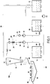
- FIG. 1 there is shown schematically a drilling mud processing unit 100 according to an exemplary embodiment of the invention.
- the primary conduit 10 is therefore connected to a tank 14 for storing coagulated drilling mud at one of its ends, and to the hydrocyclone 30 at another end.
- the primary conduit 10 is also connected, through a junction marked J on the figure 1 and located between its two ends, to a secondary conduit 22 for supplying flocculating agent.
- the secondary conduit 22 is connected by one end to the primary conduit 10 (at the junction J) and by its other end to a tank 50 of flocculating agent.
- a valve 51, a pump 52, a throttle 53 and a non-return valve 54 are located, successively in the direction of flow of this aqueous solution, between the two ends of the secondary conduit 22, as illustrated in the figure 1 .
- the pump 52 may for example be a screw pump, also called a pigtail pump or a PCM pump. This type of pump has the advantage of not shearing or little shearing the flocculating agent, which makes it possible to avoid a deterioration of its properties.
- a first valve 60, a pump 12, and a second valve 61 are located, successively in the direction of flow of the coagulated drilling mud, between the tank 14 for storing coagulated drilling mud and the junction J, in order to ensure the controlled flow of the coagulated drilling mud towards this junction J.
- the pump 12 may for example be a centrifugal pump.
- a static mixer 24 is installed on the primary conduit 10, directly downstream of the junction J, to ensure effective mixing of the flocculating agent with the coagulated drilling mud.
- a throttle 62 and a valve 63 are still located, successively in the direction of the flow of this mixture, on the primary conduit 10, between the static mixer 24 and the hydrocyclone 30.
- the primary conduit 10 can be devoid of pump downstream of the junction J, in order to avoid hampering the flocculation or destroy the flocs before their arrival in the hydrocyclone 30.
- the alternative is also possible.
- the length of the primary conduit 10 between the mixer 24 and the hydrocyclone 30 can be less than 5 meters, or even less than 2 meters.
- the hydrocyclone 30 comprises a main body 70, a tangential supply duct 72, and orifices 32, 34 of, respectively, overflow and underflow .
- the main body 70 is hollow and provided with an inverted conical part 71 of height H1.
- the tangential supply duct 72 which is connected to the primary duct 10, opens out inside the main body 70, near its top, and is oriented in a transverse plane substantially orthogonal to a central axis Z of the conical part 71, offset laterally with respect to this central axis Z, so as to give a rotational movement around this central axis X to the mixture of coagulated mud and flocculating agent when it enters the main body 70.
- the orifices 32, 34 of overflow and underflow are substantially aligned with the central axis Z of the conical part 71.
- the orifice 32 of overflow extends upwards from a mouth inside the main body 70, below the level of the conduit 72 tangential feed, and has an overflow diameter Do, while the underflow orifice 34 extends downward from inside the main body 70, to the lower tip of the conical part 71, and has a diam underflow Du.
- the overflow diameter Du is greater than 1.1 times the overflow diameter Do, and is between 1.1 and 1.6 times the overflow diameter Do.
- the main body 70 While in the hydrocyclone 30 of the first embodiment, illustrated in the Figures 2A and 2B , and which will be called Type 1, the top of the conical part 71 is substantially at the same level as the mouth of the overflow orifice 32, in the hydrocyclone 30 of the second embodiment, or Type 2, illustrated in the Figures 3A and 3B , the main body 70 also comprises a cylindrical part 73, interposed between the conical part 71 and an upper part 74, in which the conduit 72 is formed tangential supply and the orifice 32 of overflow. This cylindrical part 73 has a height H2.
- the overflow hole 32 is connected to a conduit 80 for recovering a liquid treatment product from the drilling mud which opens into a liquid tank 81.
- the underflow hole 34 opens out above a plane inclined 86 pouring onto a grid 82.
- a funnel 83 for recovering free water is disposed under the grid 82 and connected to a conduit 84 for recovering free water, also opening into the liquid tank 81.
- a pump 85 can be located on this conduit 84 for recovering free water to ensure the circulation of free water towards the tank 81.
- coagulated liquid mineral drilling mud is extracted from the tank 14 through the primary conduit 10.
- This coagulated liquid mineral drilling mud can for example be the product of 'A prior mixture of a liquid mineral drilling mud and a coagulating agent chosen from iron and / or aluminum salts, or cationic polymers.
- This treatment process is particularly advantageous for degraded drilling muds, with a density of less than 1.5 kg / dm 3 , a viscosity of more than 1 mPa ⁇ s and in which at least 80% by weight of the solid fraction is composed. inorganic matter.
- the coagulating agent can in particular be ferric chloride added to the liquid mineral mud in a proportion of up to 6 dm 3 of aqueous solution at 41% by volume of ferric chloride per cubic meter of mud.
- the diameter of the primary pipe 10 can be chosen, as a function of the flow rate, viscosity and density of the coagulated liquid mineral drilling mud, to ensure a turbulent flow of this drilling mud through the primary pipe 10.
- the diameter of the primary conduit 10 can be chosen so as to obtain a Reynolds Re number equal to or greater than 4000.
- the coagulated drilling mud is mixed with flocculating agent in aqueous solution extracted simultaneously, through the secondary conduit 22, from the tank 50 of flocculating agent.
- the flocculating agent can for example be chosen from anionic and / or cationic polyacrylamides, and particularly those with high or very high molecular weight, linear, branched or crosslinked.
- anionic polyacrylamide "high molecular weight” means a molecular weight between 10,000 and 15,000 kg / mol, and "very high molecular weight” a molecular weight between 15,000 and 20,000 kg / mol.
- the term “high molecular weight” means a molecular weight between 5,000 and 10,000 kg / mol, and by “very high molecular weight” a molecular weight greater than 10,000 kg / mol.
- the concentration of the aqueous solution of flocculating agent can be, for example, from 1 to 3 kg of flocculating agent per cubic meter, and it can be mixed with the drilling mud in a volume proportion ranging from three parts of mud of coagulated drilling for each two parts of aqueous solution of flocculating agent to nine parts of coagulated drilling mud for each part of aqueous solution of flocculating agent.
- This water free is evacuated by the recovery conduit 84 to the liquid reservoir 81.
- the liquid treatment product is also evacuated to the liquid reservoir 81, through the conduit 80. It is thus possible to obtain, by this treatment process in the processing unit 100, a solid treatment product, with a dryness which may be greater than 30%, but especially with a shoveable consistency for sending it to landfill, from a liquid mineral drilling mud.
- Example 1 Example 2 Coagulated mud density 1.2 kg / dm 3 1.2 kg / dm 3 Coagulated mud dryness 25% 25% Coagulant 41% vol. FeCl 3 aqueous solution. (4 dm 3 per m 3 of coagulated drilling mud) 41% vol. FeCl 3 aqueous solution.
Landscapes
- Engineering & Computer Science (AREA)
- Chemical & Material Sciences (AREA)
- Life Sciences & Earth Sciences (AREA)
- Environmental & Geological Engineering (AREA)
- Water Supply & Treatment (AREA)
- Mechanical Engineering (AREA)
- Organic Chemistry (AREA)
- Hydrology & Water Resources (AREA)
- Chemical Kinetics & Catalysis (AREA)
- Physics & Mathematics (AREA)
- Geology (AREA)
- Mining & Mineral Resources (AREA)
- Fluid Mechanics (AREA)
- Geometry (AREA)
- Geochemistry & Mineralogy (AREA)
- General Life Sciences & Earth Sciences (AREA)
- Analytical Chemistry (AREA)
- General Chemical & Material Sciences (AREA)
- Separation Of Suspended Particles By Flocculating Agents (AREA)
- Treatment Of Sludge (AREA)
- Excavating Of Shafts Or Tunnels (AREA)
- Processing Of Solid Wastes (AREA)
- Cyclones (AREA)
Claims (10)
- System zur Behandlung von Bohrschlamm, das Mittel zum Koagulieren von Bohrschlamm, die das Erhalten von koaguliertem Bohrschlamm ermöglichen, sowie eine Einheit zur Behandlung (100) von Bohrschlamm umfasst, umfassend:- eine Hauptleitung (10) zur Versorgung mit dem zuvor koagulierten Bohrschlamm,- ein In-Line-System (20) zur Flockung des vorhergehend koagulierten Bohrschlamms, der in der Hauptleitung (10) umläuft, und- mindestens einen Hydrozyklon (30), der durch die Hauptleitung (10) versorgt wird und stromabwärts des Flockungssystems (20) angeordnet ist, wobei der Hydrozyklon (30) eine Überlauföffnung (32), die dazu bestimmt ist, ein flüssiges Behandlungsprodukt des Bohrschlamms zu sammeln, und eine Unterlauföffnung (34) umfasst, die dazu bestimmt ist, ein festes Behandlungsprodukt des Bohrschlamms zu sammeln, wobei die Überlauföffnung (32) einen Überlaufdurchmesser (Do) aufweist und die Unterlauföffnung einen Unterlaufdurchmesser (Du) aufweist, und der Unterlaufdurchmesser (Du) mit einem Verhältnis zwischen dem Unterlaufdurchmesser (Du) und dem Überlaufdurchmesser (Do), das größer als 1,1 ist und zwischen 1,1 und 1,6 beträgt, größer als der Überlaufdurchmesser (Do) ist.
- Behandlungssystem nach Anspruch 1, wobei die Hauptversorgungsleitung (10) mit einer Pumpe (12) versehen ist und das In-Line-Flockungssystem (20) eine Nebenleitung (22) zur Versorgung mit Flockungsmittel umfasst, wobei die Nebenleitung (22) an einer Verbindung (J), die sich stromabwärts der Pumpe (12) befindet, mit der Hauptleitung (10) verbunden ist.
- Behandlungssystem nach Anspruch 2, wobei das In-Line-Flockungssystem (20) In-Line-Mittel (24) zum Mischen des koagulierten Bohrschlamms und des Flockungsmittels umfasst, die auf der Hauptleitung (10) stromabwärts der Verbindung (J) vorgesehen sind.
- Behandlungssystem nach Anspruch 3, wobei die Mischmittel (24) einen statischen Mischer umfassen.
- Behandlungssystem nach Anspruch 3 oder 4, wobei die Mischmittel (24) auf der Hauptleitung (10) in einem Abstand von dem Hydrozyklon (30) angeordnet sind, der kleiner als 5 Meter, vorzugsweise kleiner als 2 Meter, ist.
- Verfahren zur Behandlung von Bohrschlamm, das mindestens die folgende Abfolge von Schritten umfasst:- Versorgen einer Hauptversorgungsleitung (10) mit vorhergehend koaguliertem Bohrschlamm,- Ausführen der In-Line-Flockung des koagulierten Bohrschlamms, der in der Hauptleitung (10) umläuft,- Einführen des koagulierten und geflockten Bohrschlamms in einen Hydrozyklon (30), der eine Überlauföffnung (32), die einen Überlaufdurchmesser (Do) aufweist, und eine Unterlauföffnung (34) umfasst, die einen Unterlaufdurchmesser (Du) aufweist, wobei der Unterlaufdurchmesser (Du) mit einem Verhältnis zwischen dem Unterlaufdurchmesser (Du) und dem Überlaufdurchmesser (Do), das größer als 1,1 ist und zwischen 1,1 und 1,6 beträgt, größer als der Überlaufdurchmesser (Do) ist,- Ablassen eines festen Behandlungsprodukts des Bohrschlamms im Bereich der Unterlauföffnung (34) und eines flüssigen Behandlungsprodukts des Bohrschlamms im Bereich der Überlauföffnung (32).
- Behandlungsverfahren nach Anspruch 6, wobei der Bohrschlamm ein Stabilisierungsmittel, wie beispielsweise eine Bleicherde oder ein wasserlösliches organisches Polymer, umfasst.
- Behandlungsverfahren nach einem der Ansprüche 6 oder 7, wobei das feste Behandlungsprodukt des Bohrschlamms einen Trockengehalt von größer als 30% aufweist.
- Behandlungsverfahren nach einem der Ansprüche 6 bis 8, wobei das flüssige Behandlungsprodukt des Bohrschlamms Wasser ist, das weniger als 600 mg Schwebstoffe pro Liter umfasst.
- Behandlungsverfahren nach einem der Ansprüche 6 bis 9, wobei die Versorgung der Hauptleitung (10) mit vorhergehend koaguliertem Bohrschlamm im turbulenten Bereich erfolgt.
Applications Claiming Priority (2)
| Application Number | Priority Date | Filing Date | Title |
|---|---|---|---|
| FR1554508A FR3036395B1 (fr) | 2015-05-20 | 2015-05-20 | Unite de traitement d'une boue et procede correspondant |
| PCT/FR2016/051194 WO2016189232A1 (fr) | 2015-05-20 | 2016-05-19 | Unite de traitement d'une boue de forage et procede correspondant |
Publications (2)
| Publication Number | Publication Date |
|---|---|
| EP3297742A1 EP3297742A1 (de) | 2018-03-28 |
| EP3297742B1 true EP3297742B1 (de) | 2020-01-01 |
Family
ID=53496860
Family Applications (1)
| Application Number | Title | Priority Date | Filing Date |
|---|---|---|---|
| EP16731215.6A Active EP3297742B1 (de) | 2015-05-20 | 2016-05-19 | Anlage zur behandlung von bohrschlamm und entsprechendes verfahren |
Country Status (8)
| Country | Link |
|---|---|
| US (2) | US20180134599A1 (de) |
| EP (1) | EP3297742B1 (de) |
| JP (1) | JP6832293B2 (de) |
| AU (1) | AU2016269247B2 (de) |
| FR (1) | FR3036395B1 (de) |
| MY (1) | MY192907A (de) |
| SG (2) | SG10201910613RA (de) |
| WO (1) | WO2016189232A1 (de) |
Families Citing this family (4)
| Publication number | Priority date | Publication date | Assignee | Title |
|---|---|---|---|---|
| CN107774436B (zh) * | 2017-09-29 | 2019-05-14 | 云南联昂科技有限公司 | 环保智能选矿脱泥系统及其用于脱泥的方法 |
| CN110695078B (zh) * | 2019-10-16 | 2021-10-26 | 重庆大学 | 一种污染土壤异位修复装置、及其工作模式与工艺 |
| CN114516690B (zh) * | 2022-02-24 | 2023-05-23 | 武汉地质勘察基础工程有限公司 | 一种废弃泥浆处理系统及方法 |
| CN117185592B (zh) * | 2023-11-08 | 2024-01-30 | 天正浚源环保科技有限公司 | 一种深井钻井泥浆高效破胶絮凝装置 |
Family Cites Families (9)
| Publication number | Priority date | Publication date | Assignee | Title |
|---|---|---|---|---|
| JPS5575787A (en) * | 1978-12-06 | 1980-06-07 | Ebara Infuiruko Eng Service Kk | Waste water settlement separation |
| JPH06170398A (ja) * | 1992-12-10 | 1994-06-21 | Nippon Steel Corp | 活性汚泥処理における高炉水砕スラグ含有汚泥の処理方法 |
| US5422012A (en) * | 1994-08-19 | 1995-06-06 | Jrs Investments, Inc. | Technique for separating solids from drilling fluids |
| FR2833939B1 (fr) * | 2001-12-21 | 2004-10-29 | Omnium Traitement Valorisa | Procede de traitement d'eau par floculation lestee et decantation |
| JP2005205251A (ja) * | 2004-01-20 | 2005-08-04 | Mitsui Eng & Shipbuild Co Ltd | 空気圧送システム利用の浚渫土砂分級システム及び装置 |
| FR2875495B1 (fr) | 2004-09-21 | 2006-10-27 | Aluminium Pechiney Soc Par Act | Perfectionnement au procede bayer de fabrication de trihydrate d'alumine, ledit perfectionnement portant sur la separation de la liqueur d'aluminate et des residus insolubles |
| GB0603246D0 (en) * | 2006-02-17 | 2006-03-29 | Genesis Fluid Solutions Llc | Duct for use in an apparatus for separating suspended solid from water and a method feeding water having suspended solid |
| CN104603064A (zh) * | 2012-08-30 | 2015-05-06 | 东丽株式会社 | 造水方法 |
| CN103288324B (zh) * | 2013-05-28 | 2014-03-05 | 长沙理工大学 | 一种疏浚泥水原位固液分离的方法及装置 |
-
2015
- 2015-05-20 FR FR1554508A patent/FR3036395B1/fr active Active
-
2016
- 2016-05-19 WO PCT/FR2016/051194 patent/WO2016189232A1/fr not_active Ceased
- 2016-05-19 SG SG10201910613RA patent/SG10201910613RA/en unknown
- 2016-05-19 SG SG11201709488XA patent/SG11201709488XA/en unknown
- 2016-05-19 AU AU2016269247A patent/AU2016269247B2/en not_active Ceased
- 2016-05-19 US US15/574,162 patent/US20180134599A1/en not_active Abandoned
- 2016-05-19 MY MYPI2017704395A patent/MY192907A/en unknown
- 2016-05-19 JP JP2017560222A patent/JP6832293B2/ja active Active
- 2016-05-19 EP EP16731215.6A patent/EP3297742B1/de active Active
-
2020
- 2020-10-15 US US17/070,960 patent/US11465077B2/en active Active
Non-Patent Citations (1)
| Title |
|---|
| None * |
Also Published As
| Publication number | Publication date |
|---|---|
| HK1252340A1 (zh) | 2019-05-24 |
| US20210024397A1 (en) | 2021-01-28 |
| JP2018516748A (ja) | 2018-06-28 |
| US20180134599A1 (en) | 2018-05-17 |
| SG10201910613RA (en) | 2020-01-30 |
| US11465077B2 (en) | 2022-10-11 |
| WO2016189232A1 (fr) | 2016-12-01 |
| FR3036395B1 (fr) | 2018-11-23 |
| MY192907A (en) | 2022-09-14 |
| JP6832293B2 (ja) | 2021-02-24 |
| EP3297742A1 (de) | 2018-03-28 |
| AU2016269247A1 (en) | 2017-12-07 |
| AU2016269247B2 (en) | 2021-03-11 |
| FR3036395A1 (fr) | 2016-11-25 |
| SG11201709488XA (en) | 2017-12-28 |
Similar Documents
| Publication | Publication Date | Title |
|---|---|---|
| EP3297742B1 (de) | Anlage zur behandlung von bohrschlamm und entsprechendes verfahren | |
| EP2660420B1 (de) | Verbesserte Ausrüstung für Polymerauflösung in Bruchvorgänge | |
| RU2450980C2 (ru) | Передвижные системы и способы достаточной очистки воды, которая затем может применяться в операциях по обработке скважин | |
| FR2922123A1 (fr) | Installation pour la floculation de boues chargees de matieres en suspension, procede mettant en oeuvre l'installation | |
| US20090255678A1 (en) | Water Treatment by Chemical-Mechanical Process | |
| EP2632859A1 (de) | Verfahren zur trennung von flüssigen von suspendierten stoffen in einem schlamm und vorrichtung hierfür | |
| EP3328920B1 (de) | Verfahren und vorrichtung zur herstellung einer kautschukmischung in einer flüssigen phase | |
| FR3040893A1 (fr) | Materiel et procede permettant l'utilisation directe de polymere en poudre dans la fracturation hydraulique | |
| CN205714049U (zh) | 钻井固控系统钻屑分离智能环保循环撬装设备 | |
| MX2012010403A (es) | Sistema y metodo para separar los solidos de los fluidos. | |
| CN110436733B (zh) | 一种泥沙分离装置及其分离方法 | |
| EP3585836A1 (de) | Mehrphasige polymersuspension und verwendung davon | |
| EP2632860A1 (de) | Wasserklärvorrichtung und verfahren | |
| BR112021004021A2 (pt) | método e sistema de remoção de água | |
| CN104437895B (zh) | 一种泥沙和水的分离处理设备 | |
| CN106481292A (zh) | 钻机固控环保一体化循环系统 | |
| CN106285524A (zh) | 煤矿下向钻孔高分子泥浆排渣系统、方法及高分子泥浆 | |
| FR2523636A1 (fr) | Procede et installation de lixiviation in situ de minerai | |
| CN201280487Y (zh) | 一种用于油气田井下作业产出液不落地处理橇装装置 | |
| HK1252340B (en) | System for treating a drilling mud and corresponding method | |
| US7455783B2 (en) | Method for centrifugal separation enhancement | |
| WO2014076383A1 (fr) | Methode de traitement des boues minerales par floculation en ligne puis hors sol | |
| CN104310748B (zh) | 钻孔废弃泥浆处理设备 | |
| CN219334586U (zh) | 一种钻孔灌注桩成孔泥砂分离器 | |
| CN211887466U (zh) | 应用于井下煤泥水固液分离的旋流器 |
Legal Events
| Date | Code | Title | Description |
|---|---|---|---|
| STAA | Information on the status of an ep patent application or granted ep patent |
Free format text: STATUS: THE INTERNATIONAL PUBLICATION HAS BEEN MADE |
|
| PUAI | Public reference made under article 153(3) epc to a published international application that has entered the european phase |
Free format text: ORIGINAL CODE: 0009012 |
|
| STAA | Information on the status of an ep patent application or granted ep patent |
Free format text: STATUS: REQUEST FOR EXAMINATION WAS MADE |
|
| 17P | Request for examination filed |
Effective date: 20171219 |
|
| AK | Designated contracting states |
Kind code of ref document: A1 Designated state(s): AL AT BE BG CH CY CZ DE DK EE ES FI FR GB GR HR HU IE IS IT LI LT LU LV MC MK MT NL NO PL PT RO RS SE SI SK SM TR |
|
| AX | Request for extension of the european patent |
Extension state: BA ME |
|
| DAV | Request for validation of the european patent (deleted) | ||
| DAX | Request for extension of the european patent (deleted) | ||
| STAA | Information on the status of an ep patent application or granted ep patent |
Free format text: STATUS: EXAMINATION IS IN PROGRESS |
|
| 17Q | First examination report despatched |
Effective date: 20181031 |
|
| REG | Reference to a national code |
Ref country code: HK Ref legal event code: DE Ref document number: 1252340 Country of ref document: HK |
|
| GRAP | Despatch of communication of intention to grant a patent |
Free format text: ORIGINAL CODE: EPIDOSNIGR1 |
|
| STAA | Information on the status of an ep patent application or granted ep patent |
Free format text: STATUS: GRANT OF PATENT IS INTENDED |
|
| INTG | Intention to grant announced |
Effective date: 20190716 |
|
| GRAS | Grant fee paid |
Free format text: ORIGINAL CODE: EPIDOSNIGR3 |
|
| GRAA | (expected) grant |
Free format text: ORIGINAL CODE: 0009210 |
|
| STAA | Information on the status of an ep patent application or granted ep patent |
Free format text: STATUS: THE PATENT HAS BEEN GRANTED |
|
| AK | Designated contracting states |
Kind code of ref document: B1 Designated state(s): AL AT BE BG CH CY CZ DE DK EE ES FI FR GB GR HR HU IE IS IT LI LT LU LV MC MK MT NL NO PL PT RO RS SE SI SK SM TR |
|
| REG | Reference to a national code |
Ref country code: GB Ref legal event code: FG4D Free format text: NOT ENGLISH |
|
| REG | Reference to a national code |
Ref country code: CH Ref legal event code: EP Ref country code: AT Ref legal event code: REF Ref document number: 1219053 Country of ref document: AT Kind code of ref document: T Effective date: 20200115 |
|
| REG | Reference to a national code |
Ref country code: DE Ref legal event code: R096 Ref document number: 602016027302 Country of ref document: DE |
|
| REG | Reference to a national code |
Ref country code: IE Ref legal event code: FG4D Free format text: LANGUAGE OF EP DOCUMENT: FRENCH |
|
| REG | Reference to a national code |
Ref country code: NL Ref legal event code: MP Effective date: 20200101 |
|
| REG | Reference to a national code |
Ref country code: LT Ref legal event code: MG4D |
|
| PG25 | Lapsed in a contracting state [announced via postgrant information from national office to epo] |
Ref country code: CZ Free format text: LAPSE BECAUSE OF FAILURE TO SUBMIT A TRANSLATION OF THE DESCRIPTION OR TO PAY THE FEE WITHIN THE PRESCRIBED TIME-LIMIT Effective date: 20200101 Ref country code: NO Free format text: LAPSE BECAUSE OF FAILURE TO SUBMIT A TRANSLATION OF THE DESCRIPTION OR TO PAY THE FEE WITHIN THE PRESCRIBED TIME-LIMIT Effective date: 20200401 Ref country code: FI Free format text: LAPSE BECAUSE OF FAILURE TO SUBMIT A TRANSLATION OF THE DESCRIPTION OR TO PAY THE FEE WITHIN THE PRESCRIBED TIME-LIMIT Effective date: 20200101 Ref country code: LT Free format text: LAPSE BECAUSE OF FAILURE TO SUBMIT A TRANSLATION OF THE DESCRIPTION OR TO PAY THE FEE WITHIN THE PRESCRIBED TIME-LIMIT Effective date: 20200101 Ref country code: RS Free format text: LAPSE BECAUSE OF FAILURE TO SUBMIT A TRANSLATION OF THE DESCRIPTION OR TO PAY THE FEE WITHIN THE PRESCRIBED TIME-LIMIT Effective date: 20200101 Ref country code: PT Free format text: LAPSE BECAUSE OF FAILURE TO SUBMIT A TRANSLATION OF THE DESCRIPTION OR TO PAY THE FEE WITHIN THE PRESCRIBED TIME-LIMIT Effective date: 20200527 Ref country code: NL Free format text: LAPSE BECAUSE OF FAILURE TO SUBMIT A TRANSLATION OF THE DESCRIPTION OR TO PAY THE FEE WITHIN THE PRESCRIBED TIME-LIMIT Effective date: 20200101 |
|
| PG25 | Lapsed in a contracting state [announced via postgrant information from national office to epo] |
Ref country code: BG Free format text: LAPSE BECAUSE OF FAILURE TO SUBMIT A TRANSLATION OF THE DESCRIPTION OR TO PAY THE FEE WITHIN THE PRESCRIBED TIME-LIMIT Effective date: 20200401 Ref country code: GR Free format text: LAPSE BECAUSE OF FAILURE TO SUBMIT A TRANSLATION OF THE DESCRIPTION OR TO PAY THE FEE WITHIN THE PRESCRIBED TIME-LIMIT Effective date: 20200402 Ref country code: LV Free format text: LAPSE BECAUSE OF FAILURE TO SUBMIT A TRANSLATION OF THE DESCRIPTION OR TO PAY THE FEE WITHIN THE PRESCRIBED TIME-LIMIT Effective date: 20200101 Ref country code: SE Free format text: LAPSE BECAUSE OF FAILURE TO SUBMIT A TRANSLATION OF THE DESCRIPTION OR TO PAY THE FEE WITHIN THE PRESCRIBED TIME-LIMIT Effective date: 20200101 Ref country code: IS Free format text: LAPSE BECAUSE OF FAILURE TO SUBMIT A TRANSLATION OF THE DESCRIPTION OR TO PAY THE FEE WITHIN THE PRESCRIBED TIME-LIMIT Effective date: 20200501 Ref country code: HR Free format text: LAPSE BECAUSE OF FAILURE TO SUBMIT A TRANSLATION OF THE DESCRIPTION OR TO PAY THE FEE WITHIN THE PRESCRIBED TIME-LIMIT Effective date: 20200101 |
|
| REG | Reference to a national code |
Ref country code: DE Ref legal event code: R097 Ref document number: 602016027302 Country of ref document: DE |
|
| REG | Reference to a national code |
Ref country code: AT Ref legal event code: UEP Ref document number: 1219053 Country of ref document: AT Kind code of ref document: T Effective date: 20200101 |
|
| PG25 | Lapsed in a contracting state [announced via postgrant information from national office to epo] |
Ref country code: ES Free format text: LAPSE BECAUSE OF FAILURE TO SUBMIT A TRANSLATION OF THE DESCRIPTION OR TO PAY THE FEE WITHIN THE PRESCRIBED TIME-LIMIT Effective date: 20200101 Ref country code: RO Free format text: LAPSE BECAUSE OF FAILURE TO SUBMIT A TRANSLATION OF THE DESCRIPTION OR TO PAY THE FEE WITHIN THE PRESCRIBED TIME-LIMIT Effective date: 20200101 Ref country code: SK Free format text: LAPSE BECAUSE OF FAILURE TO SUBMIT A TRANSLATION OF THE DESCRIPTION OR TO PAY THE FEE WITHIN THE PRESCRIBED TIME-LIMIT Effective date: 20200101 Ref country code: SM Free format text: LAPSE BECAUSE OF FAILURE TO SUBMIT A TRANSLATION OF THE DESCRIPTION OR TO PAY THE FEE WITHIN THE PRESCRIBED TIME-LIMIT Effective date: 20200101 Ref country code: EE Free format text: LAPSE BECAUSE OF FAILURE TO SUBMIT A TRANSLATION OF THE DESCRIPTION OR TO PAY THE FEE WITHIN THE PRESCRIBED TIME-LIMIT Effective date: 20200101 Ref country code: DK Free format text: LAPSE BECAUSE OF FAILURE TO SUBMIT A TRANSLATION OF THE DESCRIPTION OR TO PAY THE FEE WITHIN THE PRESCRIBED TIME-LIMIT Effective date: 20200101 |
|
| PLBE | No opposition filed within time limit |
Free format text: ORIGINAL CODE: 0009261 |
|
| STAA | Information on the status of an ep patent application or granted ep patent |
Free format text: STATUS: NO OPPOSITION FILED WITHIN TIME LIMIT |
|
| 26N | No opposition filed |
Effective date: 20201002 |
|
| PG25 | Lapsed in a contracting state [announced via postgrant information from national office to epo] |
Ref country code: MC Free format text: LAPSE BECAUSE OF FAILURE TO SUBMIT A TRANSLATION OF THE DESCRIPTION OR TO PAY THE FEE WITHIN THE PRESCRIBED TIME-LIMIT Effective date: 20200101 Ref country code: LI Free format text: LAPSE BECAUSE OF NON-PAYMENT OF DUE FEES Effective date: 20200531 Ref country code: CH Free format text: LAPSE BECAUSE OF NON-PAYMENT OF DUE FEES Effective date: 20200531 |
|
| PG25 | Lapsed in a contracting state [announced via postgrant information from national office to epo] |
Ref country code: SI Free format text: LAPSE BECAUSE OF FAILURE TO SUBMIT A TRANSLATION OF THE DESCRIPTION OR TO PAY THE FEE WITHIN THE PRESCRIBED TIME-LIMIT Effective date: 20200101 Ref country code: PL Free format text: LAPSE BECAUSE OF FAILURE TO SUBMIT A TRANSLATION OF THE DESCRIPTION OR TO PAY THE FEE WITHIN THE PRESCRIBED TIME-LIMIT Effective date: 20200101 |
|
| REG | Reference to a national code |
Ref country code: BE Ref legal event code: MM Effective date: 20200531 |
|
| PG25 | Lapsed in a contracting state [announced via postgrant information from national office to epo] |
Ref country code: LU Free format text: LAPSE BECAUSE OF NON-PAYMENT OF DUE FEES Effective date: 20200519 |
|
| PG25 | Lapsed in a contracting state [announced via postgrant information from national office to epo] |
Ref country code: IE Free format text: LAPSE BECAUSE OF NON-PAYMENT OF DUE FEES Effective date: 20200519 |
|
| PG25 | Lapsed in a contracting state [announced via postgrant information from national office to epo] |
Ref country code: BE Free format text: LAPSE BECAUSE OF NON-PAYMENT OF DUE FEES Effective date: 20200531 |
|
| PG25 | Lapsed in a contracting state [announced via postgrant information from national office to epo] |
Ref country code: MT Free format text: LAPSE BECAUSE OF FAILURE TO SUBMIT A TRANSLATION OF THE DESCRIPTION OR TO PAY THE FEE WITHIN THE PRESCRIBED TIME-LIMIT Effective date: 20200101 Ref country code: CY Free format text: LAPSE BECAUSE OF FAILURE TO SUBMIT A TRANSLATION OF THE DESCRIPTION OR TO PAY THE FEE WITHIN THE PRESCRIBED TIME-LIMIT Effective date: 20200101 |
|
| PG25 | Lapsed in a contracting state [announced via postgrant information from national office to epo] |
Ref country code: MK Free format text: LAPSE BECAUSE OF FAILURE TO SUBMIT A TRANSLATION OF THE DESCRIPTION OR TO PAY THE FEE WITHIN THE PRESCRIBED TIME-LIMIT Effective date: 20200101 Ref country code: AL Free format text: LAPSE BECAUSE OF FAILURE TO SUBMIT A TRANSLATION OF THE DESCRIPTION OR TO PAY THE FEE WITHIN THE PRESCRIBED TIME-LIMIT Effective date: 20200101 |
|
| REG | Reference to a national code |
Ref country code: DE Ref legal event code: R082 Ref document number: 602016027302 Country of ref document: DE Representative=s name: CBDL PATENTANWAELTE GBR, DE Ref country code: DE Ref legal event code: R082 Ref document number: 602016027302 Country of ref document: DE Representative=s name: CBDL PATENTANWAELTE EGBR, DE |
|
| P01 | Opt-out of the competence of the unified patent court (upc) registered |
Effective date: 20230528 |
|
| PGFP | Annual fee paid to national office [announced via postgrant information from national office to epo] |
Ref country code: TR Payment date: 20230425 Year of fee payment: 8 |
|
| PGFP | Annual fee paid to national office [announced via postgrant information from national office to epo] |
Ref country code: DE Payment date: 20250423 Year of fee payment: 10 |
|
| PGFP | Annual fee paid to national office [announced via postgrant information from national office to epo] |
Ref country code: GB Payment date: 20250423 Year of fee payment: 10 |
|
| PGFP | Annual fee paid to national office [announced via postgrant information from national office to epo] |
Ref country code: IT Payment date: 20250423 Year of fee payment: 10 |
|
| PGFP | Annual fee paid to national office [announced via postgrant information from national office to epo] |
Ref country code: FR Payment date: 20250423 Year of fee payment: 10 |
|
| PGFP | Annual fee paid to national office [announced via postgrant information from national office to epo] |
Ref country code: AT Payment date: 20250424 Year of fee payment: 10 |