EP3302812B1 - Fluidischer oszillator - Google Patents
Fluidischer oszillator Download PDFInfo
- Publication number
- EP3302812B1 EP3302812B1 EP16733312.9A EP16733312A EP3302812B1 EP 3302812 B1 EP3302812 B1 EP 3302812B1 EP 16733312 A EP16733312 A EP 16733312A EP 3302812 B1 EP3302812 B1 EP 3302812B1
- Authority
- EP
- European Patent Office
- Prior art keywords
- flow
- main flow
- filter element
- fluidic component
- chamber
- Prior art date
- Legal status (The legal status is an assumption and is not a legal conclusion. Google has not performed a legal analysis and makes no representation as to the accuracy of the status listed.)
- Active
Links
Images


Classifications
-
- B—PERFORMING OPERATIONS; TRANSPORTING
- B05—SPRAYING OR ATOMISING IN GENERAL; APPLYING FLUENT MATERIALS TO SURFACES, IN GENERAL
- B05B—SPRAYING APPARATUS; ATOMISING APPARATUS; NOZZLES
- B05B1/00—Nozzles, spray heads or other outlets, with or without auxiliary devices such as valves, heating means
- B05B1/02—Nozzles, spray heads or other outlets, with or without auxiliary devices such as valves, heating means designed to produce a jet, spray, or other discharge of particular shape or nature, e.g. in single drops, or having an outlet of particular shape
- B05B1/08—Nozzles, spray heads or other outlets, with or without auxiliary devices such as valves, heating means designed to produce a jet, spray, or other discharge of particular shape or nature, e.g. in single drops, or having an outlet of particular shape of pulsating nature, e.g. delivering liquid in successive separate quantities
-
- B—PERFORMING OPERATIONS; TRANSPORTING
- B05—SPRAYING OR ATOMISING IN GENERAL; APPLYING FLUENT MATERIALS TO SURFACES, IN GENERAL
- B05B—SPRAYING APPARATUS; ATOMISING APPARATUS; NOZZLES
- B05B15/00—Details of spraying plant or spraying apparatus not otherwise provided for; Accessories
- B05B15/40—Filters located upstream of the spraying outlets
-
- F—MECHANICAL ENGINEERING; LIGHTING; HEATING; WEAPONS; BLASTING
- F15—FLUID-PRESSURE ACTUATORS; HYDRAULICS OR PNEUMATICS IN GENERAL
- F15C—FLUID-CIRCUIT ELEMENTS PREDOMINANTLY USED FOR COMPUTING OR CONTROL PURPOSES
- F15C1/00—Circuit elements having no moving parts
- F15C1/22—Oscillators
Definitions
- the invention relates to a fluidic component according to the preamble of claim 1 and devices comprising such a fluidic component.
- Fluidic components are provided to generate a moving fluid jet.
- a desired fluid flow pattern is generated at the component outlet without the fluidic component comprising movable elements.
- Examples of such fluid flow patterns are jet oscillations, rectangular, sawtooth-shaped or triangular jet courses, spatial or temporal jet pulsations and switching processes.
- Oscillating fluid jets are used to, for example, evenly distribute a fluid jet (or fluid stream) over a target area.
- the fluid stream can be a liquid stream, a gas stream or a multi-phase stream (e.g. wet steam).
- Fluidic components are, for example, from the US2010276521 the US 8,702,020 B2 or the US 8,733,401 B2 known. These components have a flow chamber through which a main flow of a fluid can flow.
- the flow chamber is also referred to as an interaction chamber.
- the flow chamber has at least one inlet opening, via which the fluid enters the fluidic component, and at least one outlet opening, via which the fluid exits the fluidic component.
- a means for specifically changing the direction of the fluid flow is provided for an oscillating fluid deflection at the outlet opening of the fluidic component.
- This means is designed as at least one additional flow channel (also referred to as a feedback channel).
- This feedback channel is a means for changing over a main flow which flows through the flow chamber from the inlet opening to the outlet opening.
- the means for the targeted change of direction can also be designed as a sac chamber.
- a fluid containing particles flows through the fluidic component, particles (for example foreign bodies or contaminants) can accumulate in sections of the fluidic component, so that the fluidic component can no longer perform its function or can perform it only in a deteriorated manner.
- separate filter elements for shielding are known from the prior art, either upstream of the inlet opening of the fluidic component foreign objects or use integrated filter elements directly at the inlet opening of the fluidic component.
- the particle-laden fluid thus flows around (passes) the filter elements, which are located upstream or at the inlet opening of the fluidic component and which filter the particles out before the fluid enters the fluidic component.
- additional aids for fluid filtering arranged upstream of the inlet opening causes higher costs than a fluidic component without filter elements and on the other hand increases the complexity of the systems. If the filter elements at the inlet opening of the fluidic component (as known for example from the EP 1 513 711 B1 . EP 1 053 059 B1 or EP 1 827 703 B1 ) arranged, the fluidic component can lose its function if the filter element is clogged due to foreign bodies. In addition, in the case of such components or by additional aids for fluid filtering arranged downstream of the inlet opening, the pressure loss increases compared to a fluidic component without filter elements.
- the present invention has for its object to provide a fluidic component which is particularly robust against contamination by particles or foreign bodies from a fluid laden with particles or foreign bodies.
- the fluidic component comprises a flow chamber with at least one inlet opening and at least one outlet opening, wherein the flow chamber can be flowed through by a main flow of a fluid from the at least one inlet opening to the at least one outlet opening.
- the main flow therefore has a basic direction which is directed from the at least one inlet opening to the at least one outlet opening.
- the fluidic component further comprises at least one means for specifically changing the direction of the main flow.
- the means for the targeted change of direction can in particular be a means for periodically changing the main flow.
- the fluidic component is characterized in that at least one filter element is provided, which is arranged between the means for specifically changing the direction of the main flow and the flow chamber.
- the at least one filter element can be between a means for generating a varying flow direction for the Main flow and the flow chamber may be arranged.
- the means for specifically changing the direction of the main flow can thus be a means for generating a varying flow direction for the main flow.
- the at least one filter element is therefore not arranged upstream or at the inlet opening of the fluidic component, so that only part of the fluid flow (namely the secondary flow, as will be explained later) passes through the at least one filter element. As a result, a strong pressure drop due to the presence of the at least one filter element can be avoided.
- the at least one filter element does not generally prevent particles from getting into the fluidic component. However, the at least one filter element can prevent / make it difficult for particles to get into the means for specifically changing the direction of the main flow.
- the at least one filter element which is arranged between the means for specifically changing the direction of the main flow and the flow chamber, can prevent particles from being present in the means for specifically Deposit / accumulate change of direction of the main flow and thus impair the function of this means in such a way that the fluid flow no longer exits at the outlet opening of the fluidic component as a moving fluid flow.
- a filter function for the means for the targeted change in direction of the main flow is sufficient for maintaining the function of the fluidic component through which a fluid containing particles flows. Accordingly, it is not necessary for the entire fluid flow to pass through the at least one filter element. This has probably not yet been realized because it was assumed that the function of the fluidic components would be influenced too much. Perhaps it has been assumed that the additional filter elements entail an increase in the surface area, and thus the risk of a quick smearing or calcification of the fluidic components taking place.
- a secondary flow branches off from the main flow, the secondary flow and the main flow being able to flow in different directions. While the main flow flows through the flow chamber, the secondary flow flows through the means for specifically changing the direction of the main flow. Particles that are directed by the secondary flow to the at least one filter element and collect there can be carried along by the main flow and the fluidic Leave the component through the outlet opening. This can prevent the at least one filter element from becoming blocked by an accumulation of particles and thus impair the function of the means for specifically changing the direction of the main flow in such a way that the fluid flow at the outlet opening of the fluidic component no longer exits as a moving (oscillating) fluid flow ,
- the at least one filter element can in particular be arranged between the flow chamber and the at least one means for deliberately changing the direction of the main flow in such a way that the at least one filter element is exposed to flow with a changing flow direction during operation (i.e. while a fluid flow flows through the fluidic component).
- This flow can in particular be the main flow, which oscillates due to the means for specifically changing the direction of the main flow. Due to the changing flow direction, the at least one filter element can be flushed out.
- the at least one filter element is therefore subject to a self-cleaning effect during operation.
- the at least one filter element can preferably be arranged along or parallel to one of the flow lines of the main flow.
- the alignment can be provided along streamlines which are located in the (near the wall) edge region of the main flow when the main flow is pressed against a side wall of the flow chamber or abuts against it.
- An edge region of the main flow near the wall is to be understood as an area of the main flow that is closer to a side wall of the flow chamber than to an axis that extends centrally through the flow chamber along the basic direction of the main flow.
- the at least one filter element can also be arranged in an area along or parallel to a flow line of the main flow, in which the main flow at least temporarily has a (or largest) flow velocity component that is large (or largest) in comparison to other flow lines or areas, essentially perpendicular to the basic direction of the main flow (that of the inlet opening to the outlet opening of the fluidic component is defined).
- Such an area is, for example, an area in which a recirculation area is temporarily formed (due to the means for the targeted change of direction of the main flow), which has two flow velocity components essentially perpendicular to the basic direction of the main flow, one component being directed towards the at least one filter element and the other component is directed away from the at least one filter element. In this way, an accumulation of particles can be detached from the at least one filter element.
- the at least one filter element can also be arranged in an area along or parallel to a flow line of the main flow, in which the main flow at least temporarily has a (or largest) flow velocity component in comparison to other flow lines or areas, essentially along the basic direction of the main flow.
- Such an area is, for example, an area in which the main flow temporarily flows from the inlet opening to the outlet opening of the fluidic component.
- intermittent is to be understood to mean that a flow velocity component is only present for a limited period of time, for example in the range of a few milliseconds.
- the at least one filter element can preferably be arranged in a region (between the at least one filter element and the means for deliberately changing the direction of the main flow) in which the main flow over a first period of time has a large (or largest) flow velocity component that is substantially perpendicular in comparison to other regions to the basic direction of the main flow and, over a second time period, has a large (or largest) flow velocity component in comparison to other areas, essentially along the basic direction of the main flow.
- the first and the second period can alternate (several times in succession).
- the person skilled in the art can determine this area using the usual methods known from the prior art, for example for a fluidic component without filter elements.
- first speed component that extends (essentially) perpendicular to the main flow
- second speed component with the greatest vibration amplitude, which extends (essentially) along the main flow, since this at least one filter element is thus constantly washed from different directions. Due to the high vibration amplitude of the first and second speed components, disruptive particles are transported in the direction of the main flow and removed from the component with the main flow.
- the at least one filter element can also be arranged at a position (in an area) between the flow chamber and the at least one means for specifically changing the direction of the main flow, at which the absolute change in flow velocity (transverse to the basic direction of the main flow) changes as much as possible.
- the maximum can be a local or a global maximum.
- the at least one filter element can also be arranged at a position (in a region) between the flow chamber and the at least one means for specifically changing the direction of the main flow at which the cross-section of the flow chamber or the means for specifically changing the direction of the main flow effective for the flow is minimal is. This can be a local or global minimum. If, however, the at least one filter element is incorrectly positioned, the fluidic component can lose its function.
- the at least one means for deliberately changing the direction of the main flow can have one or more feedback channels, be designed as a feedback channel or be configured as a bag chamber.
- the feedback channel or the bag chamber are in fluid communication with the flow chamber.
- the feedback channel has an input and an output, each with an opening.
- the bag chamber has an opening that forms both the entrance and the exit.
- the at least one filter element can be arranged at an opening of the at least one means for specifically changing the direction of the main flow (of the at least one feedback channel or the bag chamber).
- the at least one filter element can be arranged only at the inlet, only at the outlet or at the inlet and at the outlet of the at least one means for specifically changing the direction of the main flow.
- the at least one filter element can only be arranged at the input, only at the output or at the input and output of the feedback channel.
- the filter elements can differ from one another such that the at least one input-side filter element reduces the opening of the feedback channel at the input more than the at least one outlet-side filter element, the opening of the feedback channel, the opening at the outlet.
- the at least one filter element can be cylindrical, pyramid-shaped or conical or a rectangular, triangular, oval, round or have a polygonal cross section.
- the reduction in the cross section of the respective opening can be set.
- These parameters can be selected, for example, depending on the type of fluid and the amount, shape and size of the particles with which the fluid is loaded.
- Several filter elements can be lined up in a filter element arrangement, wherein a distance is provided between the individual filter elements and the filter elements are lined up. The filter elements can run along a straight line, follow a curvature or have any other course.
- the course can depend on the geometry of the fluidic component, the type of fluid (for example viscosity, density, surface tension, temperature) and / or the type of particles (for example size, shape, deformability).
- the exact position of the filter elements in the area of the feedback channels or bag chamber can be varied.
- the filter element arrangement takes place in a conceptual continuation of the laterally delimiting walls of the fluidic component (the flow chamber), at a position between the flow chamber and the at least one means for specifically changing the direction of the main flow.
- the filter elements can extend over the entire component depth.
- the component depth is defined essentially perpendicular to the plane in which the exiting fluid flow oscillates.
- the filter elements can be arranged at a distance from the side walls of the flow chamber and the means for specifically changing the direction of the main flow.
- a filter element arrangement (a group of filter elements) can be provided, which extends for example over the entire (or part of) the width of an opening of the means for the targeted change in direction of the fluid flow.
- the filter element arrangements extend essentially transversely (this does not necessarily mean an angle of 90 °) to the direction of flow of the secondary flows.
- filter elements or filter element arrangements can be selected such that the cross section of the feedback channel at its input is reduced more than the cross section of the feedback channel at its output.
- the distance between filter elements in the input area can be smaller than the distance between filter elements in the output area.
- filter elements can also only be provided in the input area (and not in the output area).
- the at least one filter element can have a lattice structure and / or a network structure. This structure can extend over the entire opening at the entrance / exit of the feedback channel or the bag chamber and thereby retain the particles like a sieve. By selecting the density and the strength of the grid or mesh lines of the at least one filter element, the size of the respective opening can be reduced.
- the at least one filter element can influence the function of the fluidic component and thus the fluid flow at the outlet opening of the fluidic component.
- the filter elements can change the exit angle and / or the oscillation frequency of the emerging fluid jet compared to a fluidic component without filter elements.
- a non-stick coating can be provided which prevents / complicates the deposition of particles or facilitates the washing away of the particles.
- This non-stick coating can in particular be applied to the at least one filter element.
- the non-stick coating can also be applied to the inner surface of the flow chamber and / or the means for deliberately changing the direction of the main flow.
- the at least one filter element can be designed as a rigid body.
- the at least one filter element can be at least partially flexible and / or elastically deformable.
- Fluidic components according to at least one embodiment of the invention can be used in various devices, in particular household appliances, industrial appliances or commercial appliances. Such devices are, for example, dishwashers, dishwashers, washing machines, steam cleaning devices, steamers, Convectomats, pasteurization systems, tumble dryers, devices with steam function, sterilization systems, disinfection systems.
- the fluidic component according to the invention can also be used in cleaning devices, in particular in wet cleaning process technology, such as, for example, in high-pressure cleaners, low-pressure cleaners, car washes, spray cleaning systems, descaling systems, deicing systems.
- irrigation devices are used, for example, in agriculture and agricultural technology, devices for distributing crop protection agents, blasting technology devices (devices for generating shot peening used in shot peening, devices for generating CO 2 , snow or dry ice blasting, blasting with mineral media , Compressed air jets)
- blasting technology devices devices for generating shot peening used in shot peening, devices for generating CO 2 , snow or dry ice blasting, blasting with mineral media , Compressed air jets
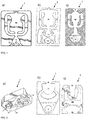
- FIG. 1 Various fluidic components are shown that are known from the prior art.
- the fluidic component Figure 1 , Drawing file a) is in the US 8,702,020 B2 discloses the fluidic components Figure 1 , Drawing files b) and c) and off Figure 2 , Drawing file b) in the EP 1 053 059 B1 , the fluidic component Figure 2 , Drawing file a) in the EP 1 513711 B1 and the fluidic component Figure 2 , Drawing file c) in the EP 2 102 922 B1 ,
- the fluidic components are generally identified by the reference number 1.
- the fluidic components 1 each have a flow chamber MC through which a (particle-laden) fluid can flow.
- the fluid enters the flow chamber MC via an inlet opening PN and exits the flow chamber MC via an outlet opening EX.
- the fluidic components 1 from Figure 1 each have two feedback channels FC as a means for specifically changing the direction of the main flow of the fluid flow.
- the fluidic components 1 from Figure 2 each have two collision channels, which are aligned with each other in such a way that the currents emerging from the collision channels collide with one another in order to generate an oscillation as a means for specifically changing the direction of the main flow of the fluid flow.
- filter elements FE are arranged for filtering particles with which the fluid entering the fluidic components 1 could be loaded.
- the filter elements FE have different shapes and arrangements.
- the fluidic components 1 from the Figures 1 and 2 however, it is common that the filter elements FE are always arranged in this way are that the entire fluid must pass through the filter elements FE in order to be able to reach the outlet opening.
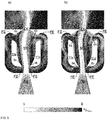
- FIG 4 A fluidic component 1 according to an embodiment of the invention is shown.
- Figure 3 shows in sub-picture a) the velocity distribution of a fluid flow that the fluidic component 1 Figure 4 flows through.
- sub-picture b) Figure 3 the flow lines of the fluid flow are also shown.
- the fluidic component 1 from Figure 4 comprises a flow chamber MC through which a fluid stream 10, 20 can flow ( Figures 3 . 7 and 20 ).
- the flow chamber MC is also referred to as an interaction chamber.
- the flow chamber MC comprises an inlet opening PN, through which the fluid flow enters the flow chamber MC, and an outlet opening EX, through which the fluid flow exits the flow chamber MC.
- the inlet opening PN and the outlet opening EX are arranged on two opposite sides of the fluidic component 1.
- the fluid flow in the flow chamber MC essentially moves along a longitudinal axis A of the fluidic component 1 (which connects the inlet opening PN and the outlet opening EX) from the inlet opening PN to the outlet opening EX.
- the longitudinal axis A forms an axis of symmetry of the fluidic component 1.
- the longitudinal axis A is the intersection line of two mutually perpendicular planes of symmetry, with respect to which the fluidic component 1 is mirror-symmetrical.
- One of the planes of symmetry is parallel to the plane of the drawing Figure 4 , Alternatively, the geometry of the fluidic component 1 cannot be constructed (mirror) symmetrically or axially symmetrically.
- two secondary flow channels (feedback channels) FC are provided for the targeted change of direction of the fluid flow, the flow chamber MC (viewed transversely to the longitudinal axis A) being arranged between the two secondary flow channels FC.
- the flow chamber MC viewed transversely to the longitudinal axis A
- only one bypass duct or more than two bypass ducts can also be provided.
- the two secondary flow channels FC branch off from the flow chamber MC. They are then brought together again immediately before (upstream) the outlet opening EX.
- the two secondary flow channels FC are arranged symmetrically with respect to the longitudinal axis A. According to an alternative, not shown, the bypass channels are not arranged symmetrically.
- the flow chamber MC connects the inlet opening PN and the outlet opening EX to one another in a substantially straight line, so that the fluid flow essentially flows along the longitudinal axis A of the fluidic component 1.
- the bypass ducts FC extend from the inlet opening PN in a first section in each case initially at an angle of essentially 90 ° to the longitudinal axis A in opposite directions. Subsequently, the bypass ducts FC bend so that they each extend essentially parallel to the longitudinal axis A (in the direction of the outlet opening EX) (second section).
- bypass ducts FC change their direction again at the end of the second section, so that they are each directed essentially in the direction of the longitudinal axis A (third section).
- the direction of the secondary flow channels FC changes by an angle of approximately 120 ° during the transition from the second to the third section.
- angles other than those mentioned here can also be selected.
- the bypass flow channels FC are a means of influencing the direction of the fluid flow that flows through the flow chamber MC.
- the bypass flow channels FC each have an input 6a, 6b, which is formed by the end of the bypass flow channels FC facing the outlet opening EX, and in each case an output 8a, 8b, which is formed by the end of the bypass flow channels FC facing the inlet opening PN.
- a small part of the fluid flow flows through the inputs 6a, 6b, the secondary flow 20 ( Figure 20 ), in the bypass channels FC.
- the remaining part of the fluid flow (the so-called main flow 10) emerges from the fluidic component 1 via the outlet opening EX (FIG. 20).
- the emerging fluid flow is in Figure 20 marked with the reference number 15.
- the secondary flows 20 emerge from the secondary flow channels FC at the outputs 8a, 8b, where they can exert a lateral (transverse to the longitudinal axis A) impulse on the fluid flow entering through the inlet opening PN.
- the direction of the fluid flow is influenced in such a way that the fluid flow 15 emerging at the outlet opening EX spatially oscillates, specifically in the plane in which the flow chamber MC and the bypass flow channels FC are arranged.
- Figure 20 which represents the oscillating fluid flow, will be explained later.
- the bypass flow channels FC each have a cross-sectional area that is almost constant over the entire length (from the input 6a, 6b to the output 8a, 8b) of the bypass flow channels FC.
- the size of the cross-sectional area of the flow chamber MC increases steadily in the flow direction of the main flow 10 (that is to say in the direction from the inlet opening PN to the outlet opening EX), the shape of the flow chamber MC being mirror-symmetrical to the two planes of symmetry.
- the flow chamber MC is separated from each bypass duct FC by a block 11a, 11b.
- the two blocks 11a, 11b are made in the embodiment Figure 4 identical in shape and size and arranged symmetrically with respect to the longitudinal axis A. In principle, however, they can also be designed differently and not be aligned symmetrically. If the alignment is not symmetrical, the shape of the flow chamber MC is also not symmetrical.
- the shape of the blocks 11a, 11b, which in Figure 4 is only exemplary and can be varied. Blocks 11a, 11b Figure 4 have rounded edges.
- Separators 105a, 105b in the form of indentations are also provided at the input 6a, 6b of the secondary flow channels FC.
- an indentation 105a, 105b projects over a section of the peripheral edge of the bypass duct FC into the respective bypass duct FC and changes its cross-sectional shape at this point while reducing the cross-sectional area.
- the section of the peripheral edge is selected such that each indentation 105a, 105b (among other things) is directed towards the inlet opening PN (oriented essentially parallel to the longitudinal axis A).
- the separators 105a, 105b can be oriented differently.
- the separators 105a, 105b influence and control the separation of the secondary flows 20 from the main flow 10.
- the shape, size and orientation of the separators 105a, 105b can influence the amount that flows from the fluid flow into the secondary flow channels FC and the direction of the secondary flows 20. This in turn influences the exit angle of the emerging fluid flow 15 at the outlet opening EX of the fluidic component 1 (and thus influences the oscillation angle) and the frequency with which the emerging fluid stream 15 oscillates at the outlet opening EX.
- the profile of the fluid stream 15 emerging at the outlet opening EX can thus be influenced in a targeted manner.
- a separator can also be provided only at the input of one of the two secondary flow channels.
- Upstream of the inlet opening PN is a funnel-shaped extension 106, which tapers in the direction of the inlet opening PN (downstream).
- the flow chamber MC also tapers in the area of the outlet opening EX.
- the taper is formed by an outlet channel 107, which extends between the separators 105a, 105b and the outlet opening EX.
- the funnel-shaped extension 106 and the outlet duct 107 taper in such a way that only their width (that is, their extension in the plane of the drawing in FIG Figure 4 perpendicular to the longitudinal axis A) decreases downstream. The taper does not affect the depth (i.e.
- the extension 106 and the outlet duct 107 can also taper in width and depth.
- the shoulder 106 can taper in depth or in width, while the outlet duct 107 tapers in both width and depth, and vice versa.
- the extent of the tapering of the outlet channel 107 influences the directional characteristic of the fluid stream 15 emerging from the outlet opening EX and thus its oscillation angle.
- the shape of the funnel-shaped extension 106 and the outlet channel 107 are shown in FIG Figure 4 shown only as an example. Here, their width decreases linearly downstream. Other forms of rejuvenation are possible.
- Filter elements FE are arranged in the area of the inputs 6a, 6b and the outputs 8a, 8b of the secondary flow channels FC.
- the filter elements FE extend in the area of the entrances 6a, 6b in the flow direction of the secondary flows in front of the separators 105a, 105b.
- Dashed lines are shown schematically, which indicate an essentially linear arrangement of individual filter elements FE in each input and output area 6a, 6b, 8a, 8b. Not every point of the dashed lines necessarily corresponds to a filter element FE. Rather, the dashed lines are only intended to illustrate the basic course (in the exemplary embodiment Figure 4 linear) of the filter elements FE show.
- the filter elements FC extend over the entire component depth.
- the filter elements FE are arranged at a distance from the blocks 11a, 11b and from the side walls of the flow chamber MC and the bypass channels FC.
- a filter element arrangement (a group of filter elements) extends over the entire width of the bypass channels FC, but can also be less wide.
- the filter element arrangements extend essentially transversely (this does not necessarily mean an angle of 90 °) to the flow direction of the secondary flows 20.
- the shape, size and number of the filter elements FE can be selected according to various criteria. The type of fluid and the amount, shape and size of the particles with which the fluid is loaded can influence the shape, size and number of filter elements FE.
- the distance between the filter elements FE in the input areas 6a, 6b is preferably smaller than that Distance between the filter elements FE in the output areas 8a, 8b.
- the filter elements FE are only provided in the input areas 6a, 6b and not in the output areas 8a, 8b.
- the filter elements FE can be positioned according to a conceptual continuation of the side walls 4a, 4b of the blocks 11a, 11b (or the flow chamber MC). In contrast to the filter position shown, the filter elements FE can also be positioned along the streamlines that arise in the flow situation in which the main flow is applied to one of the side walls 4a, 4b of the blocks 11a, 11b (or the flow chamber MC). Furthermore, the filter elements FE can be arranged in the area of the inlet 6a, 6b of the bypass duct FC and / or in the region of the outlet 8a, 8b of the bypass duct FC at a position where the largest flow velocity components (the main flow), which alternate along and across to the main flow occur.
- this position can be determined using the usual methods known from the prior art, for example for a fluidic component without filter elements. It is also possible to position the filter elements FE in the area of the narrowest cross section of the bypass channels FC. In the case of fluidic components with a separator 105a, 105b, this position is often between the separator 105a, 105b and the block 11a, 11b, which separates the flow chamber from the bypass duct FC.
- Figure 20 are three snapshots of a fluid flow to illustrate the direction of flow (streamlines) of the fluid flow in the fluidic component 1 from Figure 4 shown during an oscillation cycle ( Figures a) to c)).
- Figures a) and c) show the flow lines for two deflections of the emerging fluid flow 15, which approximately correspond to the maximum deflections. The angle that the exiting fluid stream 15 traverses between these two maxima is the oscillation angle ⁇ ( Figure 20 ).
- Figure b) shows the streamlines for a position of the emerging fluid stream 15, which lies approximately in the middle between the two maxima from the figures a) and c).
- the flows within the fluidic component 1 during an oscillation cycle are described below.
- the terms “upper bypass duct” and "lower bypass duct” are used. These only relate to the relative arrangement of the two sidestream channels in Figure 4 (not in a mandatory arrangement) and serve for better understanding.
- the fluid flow is conducted under pressure into the fluidic component 1 via the inlet opening PN.
- the fluid flow hardly experiences any in the area of the inlet opening PN Pressure loss since it can flow into the flow chamber MC undisturbed.
- the main flow 10 of the fluid flow initially flows along the longitudinal axis A in the direction of the outlet opening EX ( Figure a)).
- the fluid flow is deflected laterally in the direction of the side wall of the one block 11a facing the flow chamber MC, so that the direction of the fluid flow increasingly deviates from the longitudinal axis A until the fluid flow is maximally deflected.
- the major part of the fluid flow the so-called main flow 10 lies against the side wall of the one block 11a and then flows along this side wall.
- a recirculation area 30 is formed in the area between the main flow 10 and the other block 11b. The recirculation area 30 grows the more the main flow 10 bears against the side wall of the one block 11a.
- the main flow 10 emerges from the outlet opening EX at a time-changing angle with respect to the longitudinal axis A.
- the main flow 10 bears against the side wall of the one block 11a and the recirculation area 30 facing the block 11b has its maximum size.
- the fluid flow 15 emerges from the outlet opening EX with approximately the greatest possible deflection.
- the part of the fluid flow which flows into the secondary flow channel FC, which borders on the block 11b, on the side wall of which the main flow 10 does not abut is significantly larger than the part of the fluid flow that flows into the secondary flow channel FC, which borders on the block 11 a, on the side wall of which the main flow 10 bears.
- the secondary flow 20 in the upper secondary flow channel FC is significantly larger than the secondary flow 20 in the lower secondary flow channel FC, which is almost negligible.
- the deflection of the fluid flow into the secondary flow channels FC can be influenced and controlled using separators.
- the secondary flows 20 (in particular the secondary flow 20 in the lower secondary flow channel FC) flow through the secondary flow channels FC to their respective outlets 8a, 8b and thus give the fluid stream entering the inlet opening PN an impulse. Since the secondary flow 20 in the lower secondary flow channel FC is larger than the secondary flow 20 in the upper secondary flow channel FC, the impulse component resulting from the secondary flow 20 in the lower secondary flow channel FC predominates.
- the main flow 10 is thus pressed by the pulse (the secondary flow 20 in the lower secondary flow channel FC) against the side wall of the block 11a.
- the recirculation area 30 facing the block 11b moves in the direction of the inlet 8b of the lower bypass duct FC, whereby the supply of fluid into the lower bypass duct FC is disrupted.
- the pulse component resulting from the bypass flow 20 in the lower bypass duct FC thus decreases.
- the recirculation area 30 facing the block 11b is reduced, while a further (increasing) recirculation area 30 is formed between the main flow 10 and the side wall of the block 11a.
- the supply of fluid into the upper bypass duct FC also increases.
- the pulse component resulting from the bypass flow 20 in the upper bypass duct FC thus increases.
- the pulse components of the secondary flows 20 approach each other in the further course until they are of the same size and cancel each other out.
- the incoming fluid flow is not deflected, so that the main flow 10 moves approximately centrally between the two blocks 11a, 11b and a fluid flow 15 emerges from the outlet opening EX with almost no deflection.
- Figure 20b does not exactly show this situation, but a situation just before.
- the fluid stream 15 exiting at the outlet opening EX oscillates about the longitudinal axis A in a plane in which the flow chamber MC and the secondary flow channels FC are arranged, so that a cyclically reciprocating fluid jet generates becomes.
- a symmetrical structure of the fluidic component 1 is not absolutely necessary.
- FIG 3 is a snapshot of the unsteady flow process within the fluidic component 1 from the sub-images a) and b) Figure 4 shown, the time of recording being the same in both partial images.
- the speed of the fluid flow within the fluidic component is coded by gray levels.
- the speed field within the fluidic component represents the normalized speed of the fluid flow in the main flow direction (from the inlet opening PN to the outlet opening EX) with the maximum speed in the main flow direction.
- the color black corresponds to the normalized speed u / u max 0 and the color white corresponds to that normalized speed u / u max 1 and thus the maximum speed in the main flow direction.
- FIG. 7 three snapshots during an oscillation cycle are shown in the sub-images a) to c). Not all streamlines are shown, but only streamlines with high flow velocity.
- the filter elements FE through the Main flow 10 (at the entrance 6a, 6b), the secondary flow 20 (at the exit 8a, 8b) and through the constantly changing recirculation areas 30 (at the entrance 6a, 6b) are cleaned.
- the partial images b) and c) show, by way of example, how recirculation areas 30 move along the filter elements FE at the input 6a, 6b of the feedback channels FC and thereby change their shape.
- a filtered foreign body experiences a force acting from different directions.
- This force can ensure that the foreign body dissolves again and is then removed by the main flow 10 or by the recirculation area 30 itself.
- Foreign bodies that are filtered at the output 8a, 8b of the feedback channels FC can be removed by the secondary flow 20 which emerges from the feedback channel FC. Therefore, a greater distance between the filter elements FE in the output area 8a, 8b than in the input area 6a, 6b can be provided, so that foreign bodies that could flow through the filter elements FE in the input area 6a, 6b can also leave the feedback channel FC.
- the fluidic component Figure 4 can also be understood as a fluidic oscillator, the (one-time) targeted change in direction of the main flow 10 leading to an oscillation of the main flow 10 in the flow chamber MC and the emerging fluid flow 15.
- the fluidic component 1 from Figure 4 can not lose its function despite particles or foreign bodies with which the fluid flowing through the fluidic component 1 is afflicted.
- Another positive side effect is that the pressure loss in the fluidic component Figure 4 compared to the known fluidic components with filter elements FE, which are located in the area of the inlet area PN ( Figures 1 and 2 ), is lower, since in the known design the entire fluid flow must flow through the filter elements FE.
- the filter elements FE can be used to narrow the cross-section at the input 6a, 6b of the feedback channels FC or, respectively, and at the output 8a, 8b of the feedback channels FC.
- the filter elements can be formed by spaced apart individual bodies, whereby a reduction in the cross section of the feedback channel FC is generated in order to achieve a filter function.
- the individual (filter) bodies can be at a distance from one another which is not so small that no more fluid passes through and / or is not so large that no filter effect is achieved.
- the filter elements FE in the area of the feedback channels FC prevent a larger amount of particles or foreign bodies from penetrating into the feedback channels FC. The deposition of foreign bodies in the feedback channels FC is thus reduced or prevented. This risk of deposition in the FC feedback channels would exist without the filter elements, since the flow velocity in a feedback channel FC is usually considerably lower than the flow velocity in the flow chamber MC. The foreign bodies could thus get stuck in the feedback channels and could not be washed away.
- the fluid can clean the filter elements FE independently.
- the particles or deposits are released from the filter element FE by a recirculation area 30 (at the entrance of a bypass duct) and / or by the bypass flow 20 (at the outlet of the bypass duct), which can then be removed by the main flow 10.
- the fluidic component 1 from Figure 5 differs from that Figure 4 in particular by the arrangement of the filter elements FE.
- filter elements FE are arranged in the area of the inputs 6a, 6b and the outputs 8a, 8b of the secondary flow channels FC.
- the filter elements FE in Figure 5 not arranged in a straight line (linear), but each follow a curved course (dashed lines in Figure 5 ).
- the course at the two inputs 6a, 6b and at the two outputs 8a, 8b is mirror-symmetrical, the course at the inputs 6a, 6b being different from the course at the outputs 8a, 8b.
- the filter elements FE at the inputs 6a, 6b are viewed in the direction of flow of the secondary flows 20 (i.e. in the direction from an input 6a, 6b to the corresponding outlet 8a, 8b) according to a concave curvature and the filter elements FE at the outputs 8a, 8b viewed in the flow direction of the secondary flows 20, arranged according to a convex curvature.
- the radii of curvature of the convex and concave curvatures are different and in Figure 5 only shown as an example. Depending on the application (type of fluid (e.g. viscosity, density, surface tension, temperature), type (size, shape, deformability) and amount of particles), the radii of curvature can be selected differently.
- the radii of curvature at both inputs 6a, 6b and at both outputs 8a, 8b can be identical or different (for example, if the fluidic component is not symmetrical). All curvatures can also be convex or concave.
- Figure 6 shows further examples of the course of the filter elements FE.
- the fluidic component 1 from Figure 6 differs from that Figure 4 also in particular through the arrangement of the filter elements FE.
- the filter elements FE at the inputs 6a, 6b are thus viewed in the flow direction of the secondary flows 20 (ie in the direction of one Input 6a, 6b to the corresponding output 8a, 8b) are each arranged according to a convex curvature, but the two convex curvatures differ from one another.
- the filter elements FE at the outlet 8a viewed in the flow direction of the secondary flows 20, are arranged according to a concave curvature.
- the filter elements FE at the outlet 8b are arranged according to a zigzag line.
- the geometry for the arrangement of the filter elements FE is selected, for example, in such a way that the filter elements FE extend along the flow lines of the fluid flow.
- FIGS. 8 and 10 show two further embodiments of the fluidic component 1. These two embodiments differ from that Figure 4 in particular in that a flow divider (also called a splitter) 3 is provided in the outlet duct 107. At the inputs 6a, 6b of the secondary flow channels FC of the fluidic component 1 Figure 8 no separator is provided.
- separators 105a, 105b have one (compared to the embodiment of Figure 4 ) tapering towards the inlet opening PN.
- the shape of the blocks 11a, 11b is also different from the shape in FIG Figure 4 , The basic geometric properties of these two embodiments, however, match those of the fluidic component 1 Figure 4 match.
- the flow divider 3 has the shape of a triangular wedge, which widens in the direction of fluid flow.
- the outlet channel 107 also widens in the direction of fluid flow.
- the wedge has a depth that corresponds to the depth of the component. (The component depth is constant over the entire fluidic component 1.)
- the flow divider 3 thus divides the outlet channel 107 into two subchannels with two outlet openings EX and the fluid flow into two substrate flows that emerge from the fluidic component 1. Through the related to the Figure 4 described oscillation mechanism emerge the two substrate flows pulsed from the two outlet openings EX.
- the flow divider 3 extends substantially in the outlet duct 107, while in the embodiment it extends from Figure 10 extends into the flow chamber MC.
- the shape and size of the flow divider 3 can be freely selected depending on the desired application.
- Several flow dividers transverse to the longitudinal axis A in the oscillation plane or also transversely to the oscillation plane of the Fluid stream) can be provided to divide the emerging fluid jet into more than two substrate streams.
- Blocks 11a, 11b Figure 8 have an essentially trapezoidal basic shape which tapers downstream (in width) and from the ends of which a triangular projection projects into the flow chamber MC.
- Blocks 11a, 11b Figure 10 resemble those from Figure 4 , but have no rounded corners.
- the filter elements FE are in the Figures 8 and 10 (as in Figure 4 ) along a straight line (dashed line) in the area of the inputs 6a, 6b and the outputs 8a, 8b of the bypass channels FC.
- the fluidic component Figure 9 corresponds to that from Figure 10 and differs from the latter in particular in that no flow divider is provided.
- FIG. 11 Another embodiment of the invention is in Figure 11 shown.
- the bypass flow channels FC are separated from the flow chamber MC by the blocks 11a, 11b, the blocks 11a, 11b being essentially rectangular and each having a triangular projection which extends into the end of the blocks 11a, 11b facing the inlet opening PN Flow chamber MC protrudes.
- the flow chamber (with the exception of the region in which the triangular projections are formed) thus has a substantially constant width. Due to the shape of the blocks 11a, 11b, the individual sections of the secondary flow channels FC extend essentially parallel or perpendicular to the flow chamber MC. Separators are made in the embodiment Figure 11 not provided.
- filter elements FE are provided, which are each arranged along a curved line.
- the line is viewed in the flow direction of the secondary flows 20 (ie in the direction from an inlet 6a, 6b to the corresponding outlet 8a, 8b) in accordance with a convex curvature.
- filter elements FE are provided, which are each arranged along a straight line.
- the filter element arrangements extend essentially transversely (this does not necessarily mean an angle of 90 °) to the direction of flow of the secondary flows 20.
- FIGs 12 to 19 Various known fluidic components are shown, which additionally have filter elements FE.
- the filter elements FE are arranged according to the invention at the inputs and outputs of the secondary flow channels FC ( Figures 12-17 . 19 ).
- the bypass channel FC is short-circuited.
- an opening of the bypass duct acts as an inlet and outlet in alternation.
- the in Figure 15 shown upper opening of the secondary flow channel FC an inlet and thus the in Figure 15 shown lower opening of the secondary flow channel FC an outlet, and that until the (main) flow is pressed onto the other wall side of the flow chamber MC.
- the respective openings then switch functions.
- Sub-picture b) several feedback channels FC are provided.
- the feedback channel FC in the area of the outlet opening EX increases the pulsation over time, but does not act here as a means of changing the main flow direction.
- the filter elements FE ensure the function of the additional feedback channel FC.
- a sac chamber SK is provided as a means for specifically changing the direction of the main flow.
- the entrance of the bag chamber SK is also the exit of the bag chamber SK.
- the filter elements FE are arranged in the input / output area of the bag chamber SK.
- the fluidic components from the Figures 12 to 19 are known from the following disclosures without filter elements (or with filter elements in the region / downstream of the inlet opening of the fluidic components): EP 1 053 059 B1 ( Figure 12 , Drawing files a) and b)), WO 80/00927 ( Figure 12 , Drawing c), Figure 13 ) EP 1 658 209 B1 ( Figure 14 ) DE 2 051 804 ( Figure 15 ) DE 2 414 970 ( Figure 16 ) US 8,733,401 B2 ( Figure 17 , Drawing files a) and b)), Review of some fluid oscillators, Harry Diamond Laboratories, Washington, 1969 ( Figure 18 ) A review of Fluidic Oscillator Development and Application for Flow Control, 43rd Fluid Dynamic Conference, June 24-27, 2013 ,
- the fluidic component (1) according to the invention is suitable for fluids which are contaminated or contaminated with particles or foreign bodies, and despite the particles or foreign bodies which penetrate into the fluidic component, it maintains its function (formation of an oscillating fluid flow) and is not blocked by the particles.
- the fluidic component (1) according to the invention additionally has a self-cleaning effect since the filter elements are flushed free of the (pressurized) fluid.
- the filter elements FE can thus be cleaned by the main flow 10, the secondary flow 20 and the constantly changing recirculation areas 30.
- the changing direction of the main flow 10 and in particular the recirculation areas 30 during the oscillation process flows around and cleans the filter elements FE accordingly.
- a filtered foreign body thus experiences a force acting from different directions.
- This force can ensure that the foreign body dissolves again and is then discharged from the main flow 10 or from a recirculation area 30.
- This effect is particularly pronounced at the input 6a, 6b of the feedback channels FC (cf. Figure 7 ). Foreign bodies that are filtered in the output region 8a, 8b of the feedback channels FC can be removed by the secondary flow 20.
- the presence of the filter elements only causes a lower pressure loss, since essentially only the secondary flow has to flow through the cross-sectional constriction.
- the fluidic component has an increased service life since the integrated filter elements (and the bypass channels or bag chambers) do not become blocked. Furthermore, the arrangement of the filter elements according to the invention reduces the cost and complexity compared to systems with upstream filter systems (arranged upstream of the inlet opening of the fluidic components).
- the fluidic component according to the invention is suitable for any field of application that works with fluids.
- the fluidic component according to the invention can be used for cleaning technology.
- Another area of application is surface wetting, surface treatment or changing the surface properties by powder application or by particle collision with the surface. Typical processes for this are blasting processes, such as shot peening.
- the fluidic component according to the invention can, however, also be used in areas of application which have to do with fibrous fluids, such as in the paper industry.
- the filter elements FE can be used to influence the spray characteristics of the exiting fluid flow (exit angle of the exiting fluid flow, oscillation frequency of the exiting fluid flow).
- the spacing of the filter elements in the individual input and / or output areas of the means for the targeted change of direction of the main flow may be the same but also different.
- the distance between the filter elements FE at the entrance 6a, 6b of a feedback channel FC may be less than the distance between the filter elements FE, which are located at the output 8a, 8b of this feedback channel FC.
- the geometry of the fluidic components can basically be designed freely.
- the invention is applicable to all fluidic components which have at least one feedback channel FC or a sac chamber.
Landscapes
- Engineering & Computer Science (AREA)
- General Engineering & Computer Science (AREA)
- Theoretical Computer Science (AREA)
- Physics & Mathematics (AREA)
- Fluid Mechanics (AREA)
- Mechanical Engineering (AREA)
- Physical Or Chemical Processes And Apparatus (AREA)
- Filtering Of Dispersed Particles In Gases (AREA)
Description
- Die Erfindung betrifft ein fluidisches Bauteil nach dem Oberbegriff des Anspruchs 1 und Vorrichtungen, die ein solches fluidisches Bauteil umfassen.
- Fluidische Bauteile sind zur Erzeugung eines sich bewegenden Fluidstrahls vorgesehen. Dabei wird am Bauteilauslass ein gewünschtes Fluidfließmuster erzeugt, ohne dass das fluidische Bauteil bewegliche Elemente umfasst. Beispiele für solche Fluidfließmuster sind, Strahloszillationen, rechteckige, sägezahnförmige oder dreieckige Strahlverläufe, räumliche oder zeitliche Strahlpulsationen und Schaltvorgänge. Oszillierende Fluidstrahlen werden eingesetzt, um beispielsweise einen Fluidstrahl (oder Fluidstrom) auf ein Zielgebiet gleichmäßig zu verteilen. Der Fluidstrom kann ein Flüssigkeitsstrom, ein Gasstrom oder ein Mehrphasenstrom (zum Beispiel Nassdampf) sein.
- Fluidische Bauteile sind beispielsweise aus der
US2010276521 derUS 8,702,020 B2 oder derUS 8,733,401 B2 bekannt. Diese Bauteile weisen eine Strömungskammer auf, die von einer Hauptströmung eines Fluides durchströmbar ist. Die Strömungskammer wird auch als Wechselwirkungskammer bezeichnet. - Die Strömungskammer weist mindestens eine Einlassöffnung, über die das Fluid in das fluidische Bauteil eintritt, und mindestens eine Auslassöffnung, über die das Fluid aus dem fluidischen Bauteil austritt, auf. Für eine oszillierende Fluidumlenkung an der Auslassöffnung des fluidischen Bauteils ist ein Mittel zur gezielten Richtungsänderung des Fluidstroms vorgesehen. Bei den fluidischen Bauteilen aus der
US 8,702,020 B2 und derUS 8,733,401 B2 ist dieses Mittel als mindestens ein zusätzlicher Strömungskanal (auch als Feedback-Kanal bezeichnet) ausgebildet. Dieser Feedback-Kanal ist ein Mittel zum Umschlagen einer Hauptströmung, die die Strömungskammer von der Einlassöffnung zur Auslassöffnung durchströmt. Das Mittel zur gezielten Richtungsänderung kann auch als Sacckammer ausgebildet sein. - Wenn das fluidische Bauteil von einem partikelbehafteten Fluid durchströmt wird, können sich Partikel (zum Beispiel Fremdkörper oder Verschmutzungen) in Abschnitten des fluidischen Bauteils ansammeln, so dass das fluidische Bauteil seine Funktion nicht mehr oder nur verschlechtert ausüben kann. Um eine solche Ansammlung von Partikeln in einem fluidischen Bauteil zu vermeiden, ist aus dem Stand der Technik bekannt, entweder stromaufwärts der Einlassöffnung des fluidischen Bauteils gesonderte Filterelemente zur Abschirmung von Fremdkörpern einzusetzen oder direkt an der Einlassöffnung des fluidischen Bauteils integrierte Filterelemente zu verwenden. Das partikelbehaftete Fluid umströmt (passiert) somit die Filterelemente, die sich stromaufwärts oder an der Einlassöffnung des fluidischen Bauteils befinden und die die Partikel vor Eintritt des Fluids in das fluidische Bauteil herausfiltern.
- Der Einsatz von stromaufwärts der Einlassöffnung angeordneten zusätzlichen Hilfsmitteln zur Fluidfilterung verursacht einerseits höhere Kosten als ein fluidisches Bauteil ohne Filterelemente und erhöht anderseits die Komplexität der Systeme. Werden die Filterelemente an der Einlassöffnung des fluidischen Bauteils (wie beispielsweise bekannt aus der
EP 1 513 711 B1 ,EP 1 053 059 B1 oderEP 1 827 703 B1 ) angeordnet, so kann das fluidische Bauteil seine Funktion verlieren, wenn das Filterelement aufgrund von Fremdkörpern verstopft ist. Außerdem erhöht sich bei derartigen Bauteilen oder durch stromabwärts der Einlassöffnung angeordnete zusätzliche Hilfsmittel zur Fluidfilterung der Druckverlust gegenüber einem fluidischen Bauteil ohne Filterelemente. - Der vorliegenden Erfindung liegt die Aufgabe zugrunde, ein fluidisches Bauteil zu schaffen, das insbesondere gegenüber Verschmutzungen durch Partikel oder Fremdkörper aus einem partikel- oder fremdkörperbeladenen Fluid robust ist.
- Diese Aufgabe wird erfindungsgemäß durch ein fluidisches Bauteil mit den Merkmalen des Anspruchs 1 gelöst. Die Unteransprüche betreffen vorteilhafte Ausgestaltungen.
- Danach umfasst das fluidische Bauteil eine Strömungskammer mit mindestens einer Einlassöffnung und mindestens einer Auslassöffnung, wobei die Strömungskammer von einer Hauptströmung eines Fluids von der mindestens einen Einlassöffnung zu der mindestens einen Auslassöffnung durchstrombar ist. Die Hauptströmung weist also eine Grundrichtung auf, die von der mindestens einen Einlassöffnung zu der mindestens einen Auslassöffnung gerichtet ist. Das fluidische Bauteil umfasst ferner mindestens ein Mittel zur gezielten Richtungsänderung der Hauptströmung. Das Mittel zur gezielten Richtungsänderung kann insbesondere ein Mittel zum periodischen Umschlagen der Hauptströmung sein. Das fluidische Bauteil zeichnet sich dadurch aus, dass mindestens ein Filterelement vorgesehen ist, das zwischen dem Mittel zur gezielten Richtungsänderung der Hauptströmung und der Strömungskammer angeordnet ist. Insbesondere kann das mindestens eine Filterelement zwischen einem Mittel zur Erzeugung einer variierenden Anströmungsrichtung für die Hauptströmung und der Strömungskammer angeordnet sein. Das Mittel zur gezielten Richtungsänderung der Hauptströmung kann also ein Mittel zur Erzeugung einer variierenden Anströmungsrichtung für die Hauptströmung sein.
- Das mindestens eine Filterelement ist damit nicht stromaufwärts oder an der Einlassöffnung des fluidischen Bauteils angeordnet, so dass nur ein Teil des Fluidstroms (nämlich die Nebenströmung wie später erläutert wird) das mindestens eine Filterelement passiert. Hierdurch kann ein starker Druckabfall durch die Anwesenheit des mindestens einen Filterelements vermieden werden. Das mindestens eine Filterelement verhindert nicht generell, dass Partikel in das fluidische Bauteil gelangen. Jedoch kann das mindestens eine Filterelement verhindern/erschweren, dass Partikel in das Mittel zur gezielten Richtungsänderung der Hauptströmung gelangen. Insbesondere wenn das Mittel zur gezielten Richtungsänderung der Hauptströmung einen kleineren Innendurchmesser aufweist als die Strömungskammer, kann durch das mindestens eine Filterelement, das zwischen dem Mittel zur gezielten Richtungsänderung der Hauptströmung und der Strömungskammer angeordnet ist, vermieden werden, dass sich Partikel in dem Mittel zur gezielten Richtungsänderung der Hauptströmung ablagern/ansammeln und damit die Funktion dieses Mittels derart beinträchtigen, dass der Fluidstrom an der Auslassöffnung des fluidischen Bauteils nicht mehr als sich bewegender Fluidstrom austritt.
- Für die Funktionserhaltung des fluidischen Bauteils, das mit einem partikelbehaftetem Fluid durchströmt wird, ist eine Filterfunktion für das Mittel zur gezielten Richtungsänderung der Hauptströmung ausreichend. Demnach ist es nicht erforderlich, dass der gesamte Fluidstrom das mindestens eine Filterelement passiert. Dies wurde wahrscheinlich bisher nicht realisiert, da man davon ausging, dass die Funktion der fluidischen Bauteile dadurch zu stark beeinflusst würde. Vielleicht ist man davon ausgegangen, dass die zusätzlichen Filterelemente eine Erhöhung der Oberfläche mit sich ziehen, und somit das Risiko erhöht wird, dass eine schnellere Verschmierung oder Verkalkung der fluidischen Bauteile stattfindet.
- Im Bereich zwischen dem Mittel zur gezielten Richtungsänderung der Hauptströmung und der Strömungskammer zweigt sich eine Nebenströmung von der Hauptströmung ab, wobei die Nebenströmung und die Hauptströmung in unterschiedliche Richtungen strömen können. Während die Hauptströmung die Strömungskammer durchströmt, durchströmt die Nebenströmung das Mittel zur gezielten Richtungsänderung der Hauptströmung. Partikel, die durch die Nebenströmung auf das mindestens eine Filterelement gelenkt werden und sich dort sammeln, können durch die Hauptströmung mitgerissen werden und das fluidische Bauteil durch die Auslassöffnung verlassen. Damit kann verhindert werden, dass das mindestens eine Filterelement durch eine Ansammlung von Partikeln verstopft und damit die Funktion des Mittels zur gezielten Richtungsänderung der Hauptströmung derart beeinträchtigt wird, dass der Fluidstrom an der Auslassöffnung des fluidischen Bauteils nicht mehr als sich bewegender (oszillierender) Fluidstrom austritt.
- So kann das mindestens eine Filterelement insbesondere derart zwischen der Strömungskammer und dem mindestens einen Mittel zur gezielten Richtungsänderung der Hauptströmung angeordnet sein, dass das mindestens eine Filterelement im Betrieb (das heißt während ein Fluidstrom das fluidische Bauteil durchströmt) Strömung mit wechselnder Strömungsrichtung ausgesetzt ist. Diese Strömung kann insbesondere die Hauptströmung sein, die aufgrund des Mittels zur gezielten Richtungsänderung der Hauptströmung oszilliert. Durch die wechselnde Strömungsrichtung kann ein Freispülen des mindestens einen Filterelements erreicht werden. Das mindestens eine Filterelement unterliegt im Betrieb damit einer selbstreinigenden Wirkung.
- Vorzugsweise kann das mindestens eine Filterelement entlang beziehungsweise parallel zu einer der Stromlinien der Hauptströmung angeordnet sein. Zudem kann die Ausrichtung entlang solcher Stromlinien vorgesehen sein, die sich im (wandnahen) Randbereich der Hauptströmung befinden, wenn die Hauptströmung an eine Seitenwand der Strömungskammer gedrückt wird, beziehungsweise an dieser anliegt. Unter einem wandnahen Randbereich der Hauptströmung ist ein Bereich der Hauptströmung zu verstehen, der sich näher an einer Seitenwand der Strömungskammer befindet als an einer Achse, die sich mittig durch die Strömungskammer entlang der Grundrichtung der Hauptströmung erstreckt.
- Auch kann das mindestens eine Filterelement in einem Bereich entlang oder parallel einer Stromlinie der Hauptströmung angeordnet sein, in dem die Hauptströmung zumindest zeitweise eine im Vergleich zu anderen Stromlinien oder Bereichen große (oder größte) Strömungsgeschwindigkeitskomponente im Wesentlichen senkrecht zu der Grundrichtung der Hauptströmung (die von der Einlassöffnung zu der Auslassöffnung des fluidischen Bauteils definiert ist) aufweist. Ein solcher Bereich ist beispielsweise ein Bereich, in dem sich zeitweise (aufgrund des Mittels zur gezielten Richtungsänderung der Hauptströmung) ein Rezirkulationsgebiet ausbildet, das zwei Strömungsgeschwindigkeitskomponenten im Wesentlichen senkrecht der Grundrichtung der Hauptströmung aufweist, wobei die eine Komponente auf das mindestens eine Filterelement gerichtet ist und die andere Komponente von dem mindestens einen Filterelement weg gerichtet ist. Hierdurch kann eine Ansammlung von Partikeln von dem mindestens einen Filterelement gelöst werden.
- Auch kann das mindestens eine Filterelement in einem Bereich entlang oder parallel einer Stromlinie der Hauptströmung angeordnet sein, in dem die Hauptströmung zumindest zeitweise eine im Vergleich zu anderen Stromlinien oder Bereichen große (oder größte) Strömungsgeschwindigkeitskomponente im Wesentlichen entlang der Grundrichtung der Hauptströmung aufweist. Ein solcher Bereich ist beispielsweise ein Bereich, in dem zeitweise die Hauptströmung von der Einlassöffnung zu der Auslassöffnung des fluidischen Bauteils strömt. Hierdurch können die von dem mindestens einen Filterelement gelösten Partikel zur Auslassöffnung des fluidischen Bauteils transportiert werden.
- Der Begriff zeitweise ist dahingehend zu verstehen, dass eine Strömungsgeschwindigkeitskomponente nur über einen begrenzten Zeitraum vorliegt, der beispielsweise im Bereich von einigen Millisekunden liegt.
- Vorzugsweise kann das mindestens eine Filterelement in einem Bereich (zwischen dem mindestens einen Filterelement und dem Mittel zur gezielten Richtungsänderung der Hauptströmung) angeordnet sein, in dem die Hauptströmung über einen ersten Zeitraum eine im Vergleich zu anderen Bereichen große (oder größte) Strömungsgeschwindigkeitskomponente im Wesentlichen senkrecht zu der Grundrichtung der Hauptströmung aufweist und über einen zweiten Zeitraum eine im Vergleich zu anderen Bereichen große (oder größte) Strömungsgeschwindigkeitskomponente im Wesentlichen entlang der Grundrichtung der Hauptströmung aufweist. Dabei können sich der erste und der zweite Zeitraum (mehrfach nacheinander) abwechseln. Diesen Bereich kann der Fachmann mittels der üblichen aus dem Stand der Technik bekannten Methoden beispielsweise für ein fluidisches Bauteil ohne Filterelemente ermitteln.
- Je größer eine erste Geschwindigkeitskomponente, die sich (im Wesentlichen) senkrecht zur Hauptströmung erstreckt, ist, desto besser kann die Reinigungswirkung für das mindestens eine Filterelement sein. Diese Wirkung kann durch eine zweite (zeitlich versetzt vorliegende) Geschwindigkeitskomponente mit größter Schwingungsamplitude, die sich (im Wesentlichen) entlang der Hauptströmung erstreckt, für das mindestens eine Filterelement verstärkt werden, da dieses mindestens eine Filterelement somit ständig aus unterschiedlichen Richtungen angespült wird. Durch die hohe Schwingungsamplitude der ersten und zweiten Geschwindigkeitskomponente werden störende Partikel in Richtung der Hauptströmung transportiert und mit der Hauptströmung aus dem Bauteil entfernt.
- Das mindestens eine Filterelement kann auch an einer Position (in einem Bereich) zwischen der Strömungskammer und dem mindestens einen Mittel zur gezielten Richtungsänderung der Hauptströmung angeordnet sein, an der sich die absolute Strömungsgeschwindigkeitsänderung (quer zur Grundrichtung der Hauptströmung) maximal ändert. Das Maximum kann ein lokales oder ein globales Maximum sein. Ferner kann das mindestens eine Filterelement auch an einer Position (in einem Bereich) zwischen der Strömungskammer und dem mindestens einen Mittel zur gezielten Richtungsänderung der Hauptströmung angeordnet sein, an der der für die Strömung effektive Querschnitt der Strömungskammer beziehungsweise des Mittels zur gezielten Richtungsänderung der Hauptströmung minimal ist. Hierbei kann es sich um ein lokales oder globales Minimum handeln. Bei falscher Positionierung des mindestens einen Filterelements hingegen kann das fluidische Bauteil seine Funktion verlieren.
- Gemäß einer Ausführungsform kann das mindestens eine Mittel zur gezielten Richtungsänderung der Hauptströmung einen oder mehrere Feedback-Kanäle aufweisen, als Feedback-Kanal ausgebildet sein oder als Sackkammer ausgebildet sein. Der Feedback-Kanal beziehungsweise die Sackkammer stehen dabei in Fluidverbindung mit der Strömungskammer. Hierfür weist der Feedback-Kanal einen Eingang und einen Ausgang mit jeweils einer Öffnung auf. Die Sackkammer hingegen weist eine Öffnung auf, die sowohl den Eingang als auch den Ausgang bildet.
- Gemäß einer Ausführungsform kann das mindestens eine Filterelement an einer Öffnung des mindestens einen Mittels zur gezielten Richtungsänderung der Hauptströmung (des mindestens einen Feedback-Kanals oder der Sackkammer) angeordnet sein. Insbesondere kann das mindestens eine Filterelement nur am Eingang, nur am Ausgang oder am Eingang und am Ausgang des mindestens einen Mittels zur gezielten Richtungsänderung der Hauptströmung angeordnet sein. Beispielsweise kann das mindestens eine Filterelement nur am Eingang, nur am Ausgang oder am Eingang und am Ausgang des Feedback-Kanals angeordnet sein. In dem Fall, dass sowohl am Eingang als auch am Ausgang des Feedback-Kanals mindestens ein Filterelement vorgesehen ist, können sich die Filterelemente derart voneinander unterscheiden, dass das mindestens eine eingangsseitige Filterelement die Öffnung des Feedback-Kanals am Eingang stärker verringert als das mindestens eine auslassseitige Filterelement die Öffnung des Feedback-Kanals die Öffnung am Auslass.
- Beispielsweise kann das mindestens eine Filterelement zylinderförmig, pyramidenförmig oder kegelförmig ausgebildet sein oder einen rechteckigen, dreieckigen, ovalen, runden oder polygonalen Querschnitt aufweisen. Durch Wahl der Form, der Größe, der Anzahl und der Anordnungsdichte der Filterelemente kann die Verringerung des Querschnitts der jeweiligen Öffnung (des Feedback-Kanals oder der Sackkammer) eingestellt werden. Diese Parameter sind beispielsweise in Abhängigkeit von der Art des Fluids sowie der Menge, Form und Größe der Partikel, mit denen das Fluid beladen ist, wählbar. Mehrere Filterelemente können in einer Filterelementanordnung aneinander gereiht sein, wobei jeweils ein Abstand zwischen den einzelnen Filterelementen vorgesehen ist und die Filterelemente sich aneinander reihen. Die Filterelemente können dabei entlang einer Geraden verlaufen, einer Krümmung folgen oder einen anderen beliebigen Verlauf aufweisen. Der Verlauf kann von der Geometrie des fluidischen Bauteils, der Art des Fluids (zum Beispiel Viskosität, Dichte, Oberflächenspannung, Temperatur) und/oder der Art der Partikel (zum Beispiel Größe, Form, Verformbarkeit) abhängen. Die genaue Position der Filterelemente im Bereich der Feedback-Kanäle beziehungsweise Sackkammer kann variiert werden.
- Gemäß einer Ausführungsform erfolgt die Filterelementanordnung in einer gedanklichen Fortführung der seitlich begrenzenden Wände des fluidischen Bauteils (der Strömungskammer), an einer Position zwischen der Strömungskammer und dem mindestens einen Mittel zur gezielten Richtungsänderung der Hauptströmung.
- Die Filterelemente können sich über sie gesamte Bauteiltiefe erstrecken. Dabei ist die Bauteiltiefe im Wesentlichen senkrecht zu der Ebene definiert, in der der austretende Fluidstrom oszilliert. Die Filterelemente können von Seitenwänden der Strömungskammer und des Mittels zur gezielten Richtungsänderung des Hauptstroms beabstandet angeordnet sein. Es kann eine Filterelementanordnung (eine Gruppe von Filterelementen) vorgesehen sein, die sich beispielsweise über die gesamte (oder einen Teil der) Breite einer Öffnung des Mittels zur gezielten Richtungsänderung des Fluidstroms erstreckt. Die Filterelementanordnungen erstrecken sich im Wesentlichen quer (damit ist nicht zwingend ein Winkel von 90° gemeint) zu der Strömungsrichtung der Nebenströmungen. Bei Feedback-Kanälen können Filterelemente oder Filterelementanordnungen derart gewählt werden, dass der Querschnitt des Feedback-Kanals an seinem Eingang stärker verringert wird als der Querschnitt des Feedback-Kanals an seinem Ausgang. So kann beispielsweise der Abstand zwischen Filterelementen im Eingangsbereich kleiner als der Abstand zwischen Filterelementen im Ausgangsbereich sein. Auch können bei Feedback-Kanälen Filterelemente nur im Eingangsbereich (und nicht im Ausgangsbereich) vorgesehen sein.
- Alternativ kann das mindestens eine Filterelement eine Gitterstruktur und / oder eine Netzstruktur aufweisen. Diese Struktur kann sich über die gesamte Öffnung am Eingang/Ausgang des Feedback-Kanals beziehungsweise der Sackkammer erstrecken und dabei die Partikel wie ein Sieb zurückhalten. Dabei kann durch Wahl der Dichte und der Stärke der Gitter- beziehungsweise Netzlinien des mindestens einen Filterelements die Verringerung der Größe der jeweiligen Öffnung eingestellt werden.
- Das mindestens eine Filterelement kann je nach der genauen Positionierung zwischen der Strömungskammer und dem Mittel zur gezielten Richtungsänderung der Hauptströmung (im Eingangs- beziehungsweise Ausgangsbereich des Mittels) die Funktion des fluidischen Bauteils und damit den Fluidverlauf an der Auslassöffnung des fluidischen Bauteils beeinflussen. Die Filterelemente können den Austrittswinkel und/oder die Oszillationsfrequenz des austretenden Fluidstrahls gegenüber einem fluidischen Bauteil ohne Filterelemente verändern. Durch Wahl der Geometrieparameter des mindestens einen Filterelements beziehungsweise der Filterelementanordnung und/oder des fluidischen Bauteils können die Frequenz- und/oder Austrittswinkeländerungen des Fluidstroms, die an der Auslassöffnung des fluidischen Bauteils durch die Filterelemente hervorgerufen werden können, gemindert beziehungsweise abgestellt werden. Die Filterelemente können auch aktiv zur Beeinflussung des austretenden Fluidstroms angewandt werden. Damit kann gezielt die Abstrahlcharakteristik, z.B. den Austrittswinkel des Fluidstrahls oder die Frequenz beeinflusst werden.
- Gemäß einer weiteren Ausführungsform kann eine Antihaftbeschichtung vorgesehen sein, die das Ablagern von Partikeln verhindert/erschwert beziehungsweise das Wegspülen der Partikel erleichtert. Diese Antihaftbeschichtung kann insbesondere auf dem mindestens einen Filterelement aufgebracht sein. Alternativ oder zusätzlich kann die Antihaftbeschichtung auch auf der Innenoberfläche der Strömungskammer und/oder des Mittels zur gezielten Richtungsänderung der Hauptströmung aufgebracht sein.
- Gemäß einer weiteren Ausführungsform kann das mindestens eine Filterelement als starrer Körper ausgebildet sein. Alternativ kann das mindestens eine Filterelement zumindest teilweise flexibel und / oder elastisch verformbar ausgebildet sein.
- Fluidische Bauteile gemäß mindestens einer Ausführungsform der Erfindung können in verschiedenen Vorrichtungen, insbesondere Haushaltsgeräten, Industriegeräten oder gewerblichen Geräten zum Einsatz kommen. Solche Vorrichtungen sind beispielsweise Spülmaschinen, Geschirrspülgeräte, Waschmaschinen, Dampfreinigungsgeräte, Dampfgarer, Konvektomaten, Pasteurisieranlagen, Wäschetrockner, Geräte mit Dampffunktion, Sterilisierungsanlagen, Desinfektionsanlagen. Auch in Reinigungsgeräten, insbesondere in der Nassreinigungsverfahrenstechnik, wie beispielsweise in Hochdruckreinigern, Niederdruckreinigern, Waschstraßen, Spritzreinigungsanalgen, Entzunderungsanlagen, Enteisungsanlagen kann das erfindungsgemäße fluidische Bauteil eingesetzt werden.
- Ferner sind Bewässerungsvorrichtungen beispielsweise in der Landwirtschaft und Agrartechnik, Vorrichtungen zur Verteilung von Pflanzenschutzmitteln, Strahltechnikvorrichtungen (Vorrichtungen zur Erzeugung von Kugelstrahlen, die beim sogenannten Shot Peening zum Einsatz kommen, Vorrichtungen zur Erzeugung von CO2-, Schnee- beziehungsweise Trockeneisstrahlen, Strahlen mit mineralischen Medien, Druckluftstrahlen) Oberflächenbehandlungsvorrichtungen in Lackieranlagen und in Galvanikanlagen, Whirlpools, Mischungssysteme (Verbrennungsgeräte, Verbrennungskraftmaschinen, Heizanlagen, Einspritzsysteme, Mischanlagen, Bio-/Chemische Reaktoren), Kühlsysteme, Löschsysteme, insbesondere für Anlagen die mit Flusswasser, Meerwasser oder Seewasser arbeiten, und Wasseraufbereitungssysteme eine potentielles Anwendungsgebiet für das erfindungsgemäße fluidische Bauteil.
- Die Erfindung wird nachfolgend unter Bezugnahme auf die Figuren anhand mehrerer Ausführungsbeispiele näher erläutert. Es zeigen:
- Fig. 1
- in den Teilbildern a), b) und c) schematisch drei bekannte fluidische Bauteile mit zusätzlichen Strömungskanälen und integrierten Filterelementen jeweils im Bereich der Einlassöffnung jedes fluidischen Bauteils;
- Fig. 2
- in den Teilbildern a), b) und c) schematisch drei bekannte fluidische Bauteile mit integrierten Filterelementen jeweils im Bereich der Einlassöffnung jedes fluidischen Bauteils;
- Fig. 3
- eine Strömungssimulation für das fluidische Bauteil aus
Figur 4 , wobei in Teilbild a) die Geschwindigkeitsverteilung und in Teilbild b) die Geschwindigkeitsverteilung und die Strömungslinien dargestellt sind; - Fig. 4
- eine schematische Darstellung eines fluidischen Bauteils gemäß einer Ausführungsform der Erfindung;
- Fig. 5
- eine schematische Darstellung eines fluidischen Bauteils gemäß einer weiteren Ausführungsform der Erfindung;
- Fig. 6
- eine schematische Darstellung eines fluidischen Bauteils gemäß einer weiteren Ausführungsform der Erfindung;
- Fig. 7
- drei Momentaufnahmen (Abbildungen a) bis c)) innerhalb eines Oszillationszyklus eines Fluidstroms zur Veranschaulichung der Lage der Filterelemente des fluidischen Bauteils aus
Figur 4 bezüglich der Hauptströmung, der Nebenströmung und der Rezirkulationsgebiete; - Fig. 8
- eine schematische Darstellung eines fluidischen Bauteils gemäß einer weiteren Ausführungsform der Erfindung;
- Fig. 9
- eine schematische Darstellung eines fluidischen Bauteils gemäß einer weiteren Ausführungsform der Erfindung;
- Fig. 10
- eine schematische Darstellung eines fluidischen Bauteils gemäß einer weiteren Ausführungsform der Erfindung;
- Fig. 11
- eine schematische Darstellung eines fluidischen Bauteils gemäß einer weiteren Ausführungsform der Erfindung;
- Fig. 12:
- drei schematische Darstellungen fluidischer Bauteile gemäß weiterer Ausführungsformen der Erfindung;
- Fig. 13
- eine schematische Darstellung eines fluidischen Bauteils gemäß einer weiteren Ausführungsform der Erfindung;
- Fig. 14
- eine schematische Darstellung eines fluidischen Bauteils gemäß einer weiteren Ausführungsform der Erfindung;
- Fig. 15
- eine schematische Darstellung eines fluidischen Bauteils gemäß einer weiteren Ausführungsform der Erfindung;
- Fig. 16
- eine schematische Darstellung eines fluidischen Bauteils gemäß einer weiteren Ausführungsform der Erfindung;
- Fig. 17
- zwei schematische Darstellungen fluidischer Bauteile gemäß weiterer Ausführungsformen der Erfindung;
- Fig. 18
- eine schematische Darstellung eines fluidischen Bauteils gemäß einer weiteren Ausführungsform der Erfindung; und
- Fig. 19
- eine schematische Darstellung eines fluidischen Bauteils gemäß einer weiteren Ausführungsform der Erfindung; und
- Fig. 20
- drei Momentaufnahmen (Abbildungen a) bis c)) eines Oszillationszyklus eines Fluidstroms zur Veranschaulichung der Strömungsrichtung des Fluidstroms, der das fluidische Bauteil aus
Figur 4 durchströmt. - In den
Figuren 1 und 2 sind verschiedene fluidische Bauteile dargestellt, die aus dem Stand der Technik bekannt sind. Das fluidische Bauteil ausFigur 1 , Teilbild a) ist in derUS 8,702,020 B2 offenbart, die fluidischen Bauteile ausFigur 1 , Teilbilder b) und c) und ausFigur 2 , Teilbild b) in derEP 1 053 059 B1 , das fluidische Bauteil ausFigur 2 , Teilbild a) in derEP 1 513711 B1 und das fluidische Bauteil ausFigur 2 , Teilbild c) in derEP 2 102 922 B1 . - Die fluidischen Bauteile sind generell mit dem Bezugszeichen 1 gekennzeichnet. Die fluidischen Bauteile 1 weisen jeweils eine Strömungskammer MC auf, die von einem (partikelbeladenen) Fluid durchströmbar ist. Das Fluid tritt über eine Einlassöffnung PN in die Strömungskammer MC ein und über eine Auslassöffnung EX aus der Strömungskammer MC wieder aus. Die fluidischen Bauteile 1 aus
Figur 1 weisen als Mittel zur gezielten Richtungsänderung der Hauptströmung des Fluidstroms jeweils zwei Feedback-Kanäle FC auf. Die fluidischen Bauteile 1 ausFigur 2 weisen als Mittel zur gezielten Richtungsänderung der Hauptströmung des Fluidstroms jeweils zwei Kollisionskanäle auf, die derart zueinander ausgerichtet sind, dass die aus den Kollisionskanälen austretenden Ströme miteinander kollidieren, um so eine Oszillation zu erzeugen. - Im Bereich der Einlassöffnung PN der fluidischen Bauteile 1 aus den
Figuren 1 und 2 sind zur Filterung von Partikeln, mit denen das in die fluidischen Bauteile 1 eintretende Fluid beladen sein könnte, jeweils Filterelemente FE angeordnet. Die Filterelemente FE weisen dabei unterschiedliche Formen und Anordnungen auf. Den fluidischen Bauteilen 1 aus denFiguren 1 und 2 ist jedoch gemein, dass die Filterelemente FE stets derart angeordnet sind, dass das gesamte Fluid die Filterelemente FE passieren muss, um die Auslassöffnung erreichen zu können. - Im Folgenden werden verschiedene Ausführungsformen der Erfindung anhand der
Figuren 3 bis 19 beschrieben. - In
Figur 4 ist ein fluidisches Bauteil 1 gemäß einer Ausführungsform der Erfindung dargestellt.Figur 3 zeigt im Teilbild a) die Geschwindigkeitsverteilung eines Fluidstroms, der das fluidische Bauteil 1 ausFigur 4 durchströmt. Im Teilbild b) derFigur 3 sind zusätzlich die Strömungslinien des Fluidstroms dargestellt. - Das fluidische Bauteil 1 aus
Figur 4 umfasst eine Strömungskammer MC, die von einem Fluidstrom 10, 20 durchströmbar ist (Figuren 3 ,7 und20 ). Die Strömungskammer MC wird auch als Wechselwirkungskammer bezeichnet. - Die Strömungskammer MC umfasst eine Einlassöffnung PN, über die der Fluidstrom in die Strömungskammer MC eintritt, und eine Auslassöffnung EX, über die der Fluidstrom aus der Strömungskammer MC austritt. Die Einlassöffnung PN und die Auslassöffnung EX sind auf zwei sich gegenüberliegenden Seiten des fluidischen Bauteils 1 angeordnet. Der Fluidstrom bewegt sich in der Strömungskammer MC im Wesentlichen entlang einer Längsachse A des fluidischen Bauteils 1 (die die Einlassöffnung PN und die Auslassöffnung EX miteinander verbindet) von der Einlassöffnung PN zu der Auslassöffnung EX.
- Die Längsachse A bildet eine Symmetrieachse des fluidischen Bauteils 1. Die Längsachse A ist die Schnittgerade von zwei senkrecht zueinander stehenden Symmetrieebenen, gegenüber denen das fluidische Bauteil 1 spiegelsymmetrisch ist. Dabei ist eine der Symmetrieebenen parallel zu der Zeichenebene der
Figur 4 . Alternativ kann die Geometrie des fluidischen Bauteils 1 nicht (spiegel)symmetrisch beziehungsweise achsensymmetrisch aufgebaut sein. - Zur gezielten Richtungsänderung des Fluidstroms sind neben der Strömungskammer MC zwei Nebenstromkanäle (Feedback-Kanäle) FC vorgesehen, wobei die Strömungskammer MC (quer zur Längsachse A betrachtet) zwischen den zwei Nebenstromkanälen FC angeordnet ist. Alternativ kann/können auch nur ein Nebenstromkanal oder mehr als zwei Nebenstromkanäle vorgesehen sein. Unmittelbar hinter (stromabwärts) der Einlassöffnung PN zweigen die zwei Nebenstromkanäle FC von der Strömungskammer MC ab. Unmittelbar vor (stromaufwärts) der Auslassöffnung EX werden sie dann wieder zusammengeführt. Die zwei Nebenstromkanäle FC sind symmetrisch bezüglich der Längsachse A angeordnet. Gemäß einer nicht dargestellten Alternative sind die Nebenstromkanäle nicht symmetrisch angeordnet.
- Die Strömungskammer MC verbindet im Wesentlichen geradlinig die Einlassöffnung PN und die Auslassöffnung EX miteinander, so dass der Fluidstrom im Wesentlichen entlang der Längsachse A des fluidischen Bauteils 1 strömt. Die Nebenstromkanäle FC erstrecken sich ausgehend von der Einlassöffnung PN in einem ersten Abschnitt jeweils zunächst in einem Winkel von im Wesentlichen 90° zu der Längsachse A in entgegengesetzte Richtungen. Anschließend biegen die Nebenstromkanäle FC ab, so dass sie sich jeweils im Wesentlichen parallel zu der Längsachse A (in Richtung auf die Auslassöffnung EX) erstrecken (zweiter Abschnitt). Um die Nebenstromkanäle FC und die Strömungskammer MC wieder zusammenzuführen, ändern die Nebenstromkanäle FC am Ende des zweiten Abschnitts nochmals ihre Richtung, so dass sie jeweils im Wesentlichen in Richtung auf die Längsachse A gerichtet sind (dritter Abschnitt). In der Ausführungsform der
Figur 4 ändert sich die Richtung der Nebenstromkanäle FC beim Übergang vom zweiten in den dritten Abschnitt um einen Winkel von ca. 120°. Jedoch können für die Richtungsänderung zwischen diesen beiden Abschnitten der Nebenstromkanäle FC auch andere als der hier genannte Winkel gewählt werden. - Die Nebenstromkanäle FC sind ein Mittel zur Beeinflussung der Richtung des Fluidstromes, der die Strömungskammer MC durchströmt. Die Nebenstromkanäle FC weisen hierfür jeweils einen Eingang 6a, 6b, der durch das der Auslassöffnung EX zugewandte Ende der Nebenstromkanäle FC gebildet wird, und jeweils einen Ausgang 8a, 8b auf, der durch das der Einlassöffnung PN zugewandte Ende der Nebenstromkanäle FC gebildet wird. Durch die Eingänge 6a, 6b fließt ein kleiner Teil des Fluidstroms, die Nebenströmung 20 (
Figur 20 ), in die Nebenstromkanäle FC. Der restliche Teil des Fluidstroms (die sogenannte Hauptströmung 10) tritt über die Auslassöffnung EX aus dem fluidischen Bauteil 1 aus (Figur 20). Der austretende Fluidstrom wird inFigur 20 mit dem Bezugszeichen 15 gekennzeichnet. Die Nebenströmungen 20 treten an den Ausgängen 8a, 8b aus den Nebenstromkanälen FC aus, wo sie einen seitlichen (quer zur Längsachse A) Impuls auf den durch die Einlassöffnung PN eintretenden Fluidstrom ausüben können. Dabei wird die Richtung des Fluidstromes derart beeinflusst, dass der an der Auslassöffnung EX austretende Fluidstrom 15 räumlich oszilliert, und zwar in der Ebene, in der die Strömungskammer MC und die Nebenstromkanäle FC angeordnet sind.Figur 20 , die den oszillierenden Fluidstrom darstellt, wird später näher erläutert. - Die Nebenstromkanäle FC weisen jeweils eine Querschnittsfläche auf, die über die gesamte Länge (vom Eingang 6a, 6b bis zum Ausgang 8a, 8b) der Nebenstromkanäle FC nahezu konstant ist. Demgegenüber nimmt die Größe der Querschnittsfläche der Strömungskammer MC in Strömungsrichtung der Hauptströmung 10 (also in Richtung von der Einlassöffnung PN zu der Auslassöffnung EX) stetig zu, wobei die Form der Strömungskammer MC spiegelsymmetrisch zu den beiden Symmetrieebenen ist.
- Die Strömungskammer MC ist von jedem Nebenstromkanal FC durch einen Block 11a, 11b getrennt. Die zwei Blöcke 11a, 11b sind in der Ausführungsform aus
Figur 4 identisch in Form und Größe und symmetrisch bezüglich der Längsachse A angeordnet. Prinzipiell können sie jedoch auch unterschiedlich ausgebildet und nicht symmetrisch ausgerichtet sein. Bei nicht symmetrischer Ausrichtung ist auch die Form der Strömungskammer MC nicht symmetrisch. Die Form der Blöcke 11a, 11b, die inFigur 4 dargestellt ist, ist nur beispielhaft und kann variiert werden. Die Blöcke 11a, 11b ausFigur 4 weisen abgerundete Kanten auf. - Am Eingang 6a, 6b der Nebenstromkanäle FC sind zudem Separatoren 105a, 105b in Form von Einbuchtungen vorgesehen. Dabei ragt am Eingang 6a, 6b jedes Nebenstromkanals FC jeweils eine Einbuchtung 105a, 105b über einen Abschnitt der Umfangskante des Nebenstromkanals FC in den jeweiligen Nebenstromkanal FC und verändert an dieser Stelle unter Verkleinerung der Querschnittsfläche dessen Querschnittsform. In der Ausführungsform der
Figur 4 ist der Abschnitt der Umfangskante so gewählt, dass jede Einbuchtung 105a, 105b (unter anderem auch) auf die Einlassöffnung PN (im Wesentlichen parallel zu der Längsachse A ausgerichtet) gerichtet ist. Alternativ können die Separatoren 105a, 105b anders ausgerichtet sein. Durch die Separatoren 105a, 105b wird die Abtrennung der Nebenströmungen 20 von der Hauptströmung 10 beeinflusst und gesteuert. Durch Form, Größe und Ausrichtung der Separatoren 105a, 105b kann die Menge, die aus dem Fluidstrom in die Nebenstromkanäle FC strömt, sowie die Richtung der Nebenströmungen 20 beeinflusst werden. Das führt wiederum zu einer Beeinflussung des Austrittswinkels des austretenden Fluidstroms 15 an der Auslassöffnung EX des fluidischen Bauteils 1 (und damit zu einer Beeinflussung des Oszillationswinkels) sowie der Frequenz, mit der der austretende Fluidstrom 15 an der Auslassöffnung EX oszilliert. Durch Wahl der Größe, Orientierung und/oder Form der Separatoren 105a, 105b kann somit gezielt das Profil des an der Auslassöffnung EX austretenden Fluidstroms 15 beeinflusst werden. Alternativ kann auch nur am Eingang eines der beiden Nebenstromkanäle ein Separator vorgesehen sein. Der Einlassöffnung PN ist stromaufwärts ein trichterförmiger Ansatz 106 vorgeschaltet, der sich in Richtung auf die Einlassöffnung PN (stromabwärts) verjüngt. Auch die Strömungskammer MC verjüngt sich, und zwar im Bereich der Auslassöffnung EX. Die Verjüngung wird von einem Auslasskanal 107 gebildet, der sich zwischen den Separatoren 105a, 105b und der Auslassöffnung EX erstreckt. Dabei verjüngen sich der trichterförmige Ansatz 106 und der Auslasskanal 107 derart, dass nur deren Breite (das heißt deren Ausdehnung in der Zeichenebene inFigur 4 senkrecht zu der Längsachse A) jeweils stromabwärts abnimmt. Die Verjüngung wirkt sich nicht auf die Tiefe (das heißt die Ausdehnung senkrecht zur Zeichenebene inFigur 4 ) des Ansatzes 106 und des Auslasskanals 107 aus. Alternativ können sich der Ansatz 106 und der Auslasskanal 107 auch jeweils in der Breite und in der Tiefe verjüngen. Ferner kann sich nur der Ansatz 106 in der Tiefe oder in der Breite verjüngen, während sich der Auslasskanal 107 sowohl in der Breite als auch in der Tiefe verjüngt, und umgekehrt. Das Ausmaß der Verjüngung des Auslasskanals 107 beeinflusst die Richtcharakteristik des aus der Auslassöffnung EX austretenden Fluidstroms 15 und somit dessen Oszillationswinkel. Die Form des trichterförmigen Ansatzes 106 und des Auslasskanals 107 sind inFigur 4 nur beispielhaft gezeigt. Hier nimmt deren Breite stromabwärts jeweils linear ab. Andere Formen der Verjüngung sind möglich. - Im Bereich der Eingänge 6a, 6b und der Ausgänge 8a, 8b der Nebenstromkanäle FC sind jeweils Filterelemente FE angeordnet. Dabei erstrecken sich die Filterelemente FE im Bereich der Eingänge 6a, 6b in Strömungsrichtung der Nebenströmungen betrachtet vor den Separatoren 105a, 105b. In
Figur 4 sind schematisch gestrichelte Linien abgebildet, die eine im Wesentlichen lineare Anordnung einzelner Filterelemente FE in jedem Eingangs- und Ausgangsbereich 6a, 6b, 8a, 8b andeuten. Dabei entspricht nicht jeder Punkt der gestrichelten Linien zwangsweise einem Filterelement FE. Vielmehr sollen die gestrichelten Linien lediglich den prinzipiellen Verlauf (im Ausführungsbeispiel ausFigur 4 linear) der Filterelemente FE zeigen. Die Filterelemente FC erstrecken sich über die gesamte Bauteiltiefe. Die Filterelemente FE sind von den Blöcken 11a, 11b und von den Seitenwänden der Strömungskammer MC und der Nebenstromkanäle FC beabstandet angeordnet. Eine Filterelementanordnung (eine Gruppe von Filterelementen) erstreckt sich über die gesamte Breite der Nebenstromkanäle FC, kann jedoch auch weniger breit sein. Die Filterelementanordnungen erstrecken sich im Wesentlichen quer (damit ist nicht zwingend ein Winkel von 90° gemeint) zu der Strömungsrichtung der Nebenströmungen 20. Die Form, Größe und Anzahl der Filterelemente FE ist nach verschiedenen Kriterien wählbar. So können die Art des Fluids sowie die Menge, Form und Größe der Partikel, mit denen das Fluid beladen ist, die Form, Größe und Anzahl der Filterelemente FE beeinflussen. Vorzugsweise ist der Abstand zwischen den Filterelementen FE in den Eingangsbereichen 6a, 6b kleiner als der Abstand zwischen den Filterelementen FE in den Ausgangsbereichen 8a, 8b. Alternativ sind die Filterelemente FE nur in den Eingangsbereichen 6a, 6b vorgesehen und nicht in den Ausgangsbereichen 8a, 8b. - Die Filterelemente FE können gemäß einer gedanklichen Fortführung der seitlichen Wände 4a, 4b der Blöcke 11a, 11b (beziehungsweise der Strömungskammer MC) positioniert werden. Im Gegensatz zu der dargestellten Filterposition können die Filterelemente FE auch entlang der Stromlinien positioniert werden, die in der Strömungssituation entstehen, bei der die Hauptströmung an einer der seitlichen Wände 4a, 4b der Blöcke 11a, 11b (beziehungsweise der Strömungskammer MC) anliegt. Ferner können die Filterelemente FE im Bereich des Eingangs 6a, 6b des Nebenstromkanals FC und / oder im Bereich des Ausgangs 8a, 8b des Nebenstromkanals FC an einer Position angeordnet werden, an der die größten Strömungsgeschwindigkeitskomponenten (der Hauptströmung), die sich abwechselnd entlang und quer zur Hauptströmung befinden, auftreten. Diese Position kann der Fachmann mittels der üblichen aus dem Stand der Technik bekannten Methoden beispielsweise für ein fluidisches Bauteil ohne Filterelemente ermitteln. Auch ist es möglich, die Filterelemente FE im Bereich des engsten Querschnittes der Nebenstromkanäle FC zu positionieren. Bei fluidischen Bauteilen mit einem Separator 105a, 105b ist diese Position häufig zwischen dem Separator 105a, 105b und dem Block 11a, 11b, der die Strömungskammer vom Nebenstromkanal FC trennt.
- In
Figur 20 sind drei Momentaufnahmen eines Fluidstroms zur Veranschaulichung der Strömungsrichtung (Stromlinien) des Fluidstroms in dem fluidischen Bauteil 1 ausFigur 4 während eines Oszillationszyklus dargestellt (Abbildungen a) bis c)). In den Abbildungen a) und c) sind die Stromlinien für zwei Auslenkungen des austretenden Fluidstroms 15 dargestellt, die annähernd den maximalen Auslenkungen entsprechen. Der Winkel, den der austretende Fluidstrom 15 zwischen diesen beiden Maxima überstreicht ist der Oszillationswinkel α (Figur 20 ). Abbildung b) zeigt die Stromlinien für eine Position des austretenden Fluidstroms 15, die ungefähr in der Mitte zwischen den beiden Maxima aus den Abbildungen a) und c) liegt. Im Folgenden werden die Strömungen innerhalb des fluidischen Bauteils 1 während eines Oszillationszyklus beschrieben. Dabei werden die Begriffe "oberer Nebenstromkanal" und "unterer Nebenstromkanal" verwendet. Diese beziehen sich lediglich auf die relative Anordnung der zwei Nebenstromkanäle inFigur 4 (nicht auf zwingend erforderliche Anordnung) und dienen dem besseren Verständnis. - Zunächst wird der Fluidstrom unter Druck über die Einlassöffnung PN in das fluidische Bauteil 1 geleitet. Der Fluidstrom erfährt im Bereich der Einlassöffnung PN kaum einen Druckverlust, da er ungestört in die Strömungskammer MC strömen kann. Die Hauptströmung 10 des Fluidstroms strömt zunächst entlang der Längsachse A in Richtung auf die Auslassöffnung EX (Abbildung a)).
- Durch Einbringen einer einmaligen zufälligen oder gezielten Störung wird der Fluidstrom seitlich in Richtung der der Strömungskammer MC zugewandten Seitenwand des einen Blockes 11a ausgelenkt, so dass die Richtung des Fluidstroms zunehmend von der Längsachse A abweicht bis der Fluidstrom maximal ausgelenkt ist. Durch den sogenannten Coandä-Effekt legt sich der größte Teil des Fluidstroms, die sogenannte Hauptströmung 10, dabei an die Seitenwand des einen Blockes 11a an und strömt dann entlang dieser Seitenwand. Im Bereich zwischen der Hauptströmung 10 und dem anderen Block 11b bildet sich ein Rezirkulationsgebiet 30 aus. Dabei wächst das Rezirkulationsgebiet 30 je mehr sich die Hauptströmung 10 an die Seitenwand des einen Blockes 11a anlegt. Die Hauptströmung 10 tritt unter einem sich zeitlich ändernden Winkel bezüglich der Längsachse A aus der Auslassöffnung EX aus. In
Figur 20a ) liegt die Hauptströmung 10 an der Seitenwand des einen Blockes 11a an und das dem Block 11b zugewandte Rezirkulationsgebiet 30 weist seine maximale Größe auf. Zudem tritt der Fluidstrom 15 mit annähernd größtmöglicher Auslenkung aus der Auslassöffnung EX aus. - Ein kleiner Teil des Fluidstroms, die sogenannte Nebenströmung 20, trennt sich von der Hauptströmung 10 und strömt in die Nebenstromkanäle FC über deren Eingänge 6a, 6b. In der in
Figur 20a ) dargestellten Situation ist (aufgrund der Auslenkung des Fluidstroms in Richtung des Blockes 11a) der Teil des Fluidstroms, der in den Nebenstromkanal FC fließt, der an den Block 11b grenzt, an dessen Seitenwand sich die Hauptströmung 10 nicht anlegt, deutlich größer als der Teil des Fluidstroms, der in den Nebenstromkanal FC fließt, der an den Block 11a grenzt, an dessen Seitenwand sich die Hauptströmung 10 anlegt. InFigur 20a ) ist also die Nebenströmung 20 in dem oberen Nebenstromkanal FC deutlich größer als die Nebenströmung 20 in dem unteren Nebenstromkanal FC, die nahezu vernachlässigbar ist. In der Regel kann die Umlenkung des Fluidstroms in die Nebenstromkanäle FC mit Separatoren beeinflusst und gesteuert werden. Die Nebenströmungen 20 (insbesondere die Nebenströmung 20 in dem unteren Nebenstromkanal FC) fließen durch die Nebenstromkanäle FC zu deren jeweiligen Ausgängen 8a, 8b und geben damit dem an der Einlassöffnung PN eintretenden Fluidstrom einen Impuls. Da die Nebenströmung 20 in dem unteren Nebenstromkanal FC größer ist als die Nebenströmung 20 in dem oberen Nebenstromkanal FC, überwiegt die Impulskomponente, die aus der Nebenströmung 20 in dem unteren Nebenstromkanal FC resultiert. - Die Hauptströmung 10 wird also durch den Impuls (der Nebenströmung 20 in dem unteren Nebenstromkanal FC) an die Seitenwand des Blockes 11a gedrückt. Gleichzeitig bewegt sich das dem Block 11b zugewandte Rezirkulationsgebiet 30 in Richtung auf den Eingang 8b des unteren Nebenstromkanals FC, wodurch die Zufuhr von Fluid in den unteren Nebenstromkanal FC gestört wird. Die Impulskomponente, die von der Nebenströmung 20 in dem unteren Nebenstromkanal FC resultiert, nimmt damit ab. Gleichzeitig verkleinert sich das dem Block 11b zugewandte Rezirkulationsgebiet 30, während sich ein weiteres (anwachsendes) Rezirkulationsgebiet 30 zwischen der Hauptströmung 10 und der Seitenwand des Blockes 11a ausbildet. Hierbei nimmt auch die Zufuhr von Fluid in den oberen Nebenstromkanal FC zu. Die Impulskomponente, die von der Nebenströmung 20 in dem oberen Nebenstromkanal FC resultiert, nimmt damit zu. Die Impulskomponenten der Nebenströmungen 20 nähern sich im weiteren Verlauf immer weiter an, bis sie gleich groß sind und sich gegenseitig aufheben. In dieser Situation wird der eintretende Fluidstrom nicht abgelenkt, so dass sich die Hauptströmung 10 ungefähr mittig zwischen den beiden Blöcken 11a, 11b bewegt und ein Fluidstrom 15 nahezu ohne Auslenkung aus der Auslassöffnung EX austritt.
Figur 20b ) zeigt nicht exakt diese Situation, sondern eine Situation kurz zuvor. - Im weiteren Verlauf nimmt die Zufuhr von Fluid in den oberen Nebenstromkanal FC immer weiter zu, so dass die Impulskomponente, die von der Nebenströmung 20 in dem oberen Nebenstromkanal FC resultiert, die Impulskomponente, die von der Nebenströmung 20 in dem unteren Nebenstromkanal FC resultiert, übersteigt. Die Hauptströmung 10 wird dadurch immer weiter von der Seitenwand des Blockes 11a weggedrängt bis er an der Seitenwand des gegenüberliegenden Blockes 11b aufgrund des Coandä-Effekts anliegt (
Figur 20c )). Das Rezirkulationsgebiet 30, das dem Block 11b zugewandt ist, löst sich dabei auf, während das Rezirkulationsgebiet 30, das dem Block 11a zugewandt ist, zu seiner maximalen Größe anwächst. Die Hauptströmung 10 tritt nun mit maximaler Auslenkung, die im Vergleich zu der Situation ausFigur 20a ) ein umgekehrtes Vorzeichen aufweist, aus der Auslassöffnung EX aus. - Anschließend wird das Rezirkulationsgebiet 30, das dem Block 11a zugewandt ist, wandern und den Eingang 6a des oberen Nebenstromkanals FC blockieren, so dass die Zufuhr von Fluid hier wieder sinkt. In der Folge wird die Nebenströmung 20 in dem unteren Nebenstromkanal FC die dominierende Impulskomponente liefern, so dass die Hauptströmung 10 wieder von der Seitenwand des Blocks 11b weggedrückt wird. Die beschriebenen Änderungen erfolgen nun in umgekehrter Reihenfolge.
- Durch den Aufbau des fluidischen Bauteils und den beschriebenen Vorgang oszilliert der an der Auslassöffnung EX austretende Fluidstrom 15 um die Längsachse A in einer Ebene, in der die Strömungskammer MC und die Nebenstromkanäle FC angeordnet sind, so dass ein zyklisch hin- und her schweifender Fluidstrahl erzeugt wird. Um den beschriebenen Effekt zu erreichen, ist ein symmetrischer Aufbau des fluidischen Bauteils 1 nicht zwingend notwendig.
- In
Figur 3 ist in den Teilbildern a) und b) jeweils eine Momentaufnahme des instationären Strömungsvorgangs innerhalb des fluidischen Bauteils 1 ausFigur 4 dargestellt, wobei in beiden Teilbildern der Zeitpunkt der Aufnahme gleich ist. Die Geschwindigkeit des Fluidstroms innerhalb des fluidischen Bauteils ist durch Graustufen kodiert. Dabei stellt das Geschwindigkeitsfeld innerhalb des fluidischen Bauteils die normierte Geschwindigkeit des Fluidstroms in Hauptströmungsrichtung (von der Einlassöffnung PN zur Auslassöffnung EX) mit der maximalen Geschwindigkeit in Hauptströmungsrichtung dar. Die Farbe schwarz entspricht der normierten Geschwindigkeit u/umax 0 und die Farbe weiß entspricht der normierten Geschwindigkeit u/umax 1 und somit der maximalen Geschwindigkeit in Hauptströmungsrichtung. - In Teilbild b) der
Figur 3 sind zur zusätzlichen Visualisierung außerdem Strömungslinien dargestellt. Zwischen der Auslassöffnung EX und den Filterelementen FE am Eingang 6b des inFigur 3 rechten Nebenstromkanals FC ist ein Bereich zur erkennen, wo eine Stromlinie eine geschlossene Kurve (Rezirkulationsgebiet) bildet. In dieser momentanen Strömungssituation wirken auf die Filterelemente FE Querkräfte beziehungsweise weist die Strömung hier hohe Querkomponenten bezüglich der Hauptströmungsrichtung auf. Durch den Oszillationsmechanismus wird das inFigur 3 gezeigte Rezirkulationsgebiet aufgelöst, wobei ein anderes Rezirkulationsgebiet zwischen der Auslassöffnung EX und den Filterelementen FE am Eingang 6a des inFigur 3 linken Nebenstromkanals FC entsteht. Durch diese Dynamik werden die einzelnen Filterelemente FE quer bezüglich der Hauptströmungsrichtung abwechselnd angeströmt. Diese Strömungssituation sorgt dafür, dass eventuell an einem Filterelement FE anliegende Partikel wieder in Richtung der Hauptströmung befördert werden und dann von der Hauptströmung mitgerissen werden. Damit kann die selbstreinigende Wirkung des fluidischen Bauteils erreicht werden. - In
Figur 7 sind drei Momentaufnahmen während eines Oszillationszyklus in den Teilbildern a) bis c) dargestellt. Dabei sind nicht alle Stromlinien, sondern nur Stromlinien mit hoher Strömungsgeschwindigkeit gezeigt. Prinzipiell können die Filterelemente FE durch die Hauptströmung 10 (am Eingang 6a, 6b), die Nebenströmung 20 (am Ausgang 8a, 8b) sowie durch die sich ständig ändernden Rezirkulationsgebiete 30 (am Eingang 6a, 6b) gereinigt werden. In den Teilbildern b) und c) ist beispielhaft gezeigt, wie sich Rezirkulationsgebiete 30 an den Filterelementen FE am Eingang 6a, 6b der Feedback-Kanäle FC entlang bewegen und dabei ihre Form ändern. Dabei erfährt ein gefilterter Fremdkörper eine aus unterschiedlichen Richtungen angreifende Kraft. Diese Kraft kann dafür sorgen, dass der Fremdkörper sich wieder löst und dann von der Hauptströmung 10 oder von dem Rezirkulationsgebiet 30 selbst abgeführt wird. Fremdkörper, die am Ausgang 8a, 8b der Feedback-Kanäle FC gefiltert werden, können durch die Nebenströmung 20 entfernt werden, die aus dem Feedback-Kanal FC austritt. Daher kann ein höherer Abstand der Filterelemente FE im Ausgangsbereich 8a, 8b als im Eingangsbereich 6a, 6b vorgesehen sein, damit Fremdkörper, die durch die Filterelemente FE im Eingangsbereich6a, 6b durchfließen konnten, auch den Feedback-Kanal FC verlassen können. - Das fluidische Bauteil aus
Figur 4 kann auch als fluidischer Oszillator aufgefasst werden, wobei die (einmalige) gezielte Richtungsänderung der Hauptströmung 10 zu einer Oszillation der Hauptströmung 10 in der Strömungskammer MC und des austretenden Fluidstroms 15 führt. Das fluidische Bauteil 1 ausFigur 4 kann trotz Partikeln beziehungsweise Fremdkörpern, mit denen das das fluidische Bauteil 1 durchströmende Fluid behaftetet ist, seine Funktion nicht verlieren. Ein weiterer positiver Nebeneffekt ist, dass der Druckverlust bei dem fluidischen Bauteil ausFigur 4 gegenüber den bekannten fluidischen Bauteilen mit Filterelementen FE, die sich im Bereich des Einlassbereiches PN befinden (Figuren 1 und 2 ), geringer ist, da bei der bekannten Bauform der gesamte Fluidstrom die Filterelemente FE durchströmen muss. - Durch die Filterelemente FE kann eine Querschnittsverengung am Eingang 6a, 6b der Feedback-Kanäle FC oder beziehungsweise und am Ausgang 8a, 8b der Feedback-Kanäle FC geschaffen werden. Die Filterelemente können als durch voneinander beabstandete einzelne Körper ausgebildet sein, wodurch eine Verringerung des Querschnitts des Feedback-Kanäle FC generiert wird, um eine Filterfunktion zu erreichen. Die einzelnen (Filter)Körper können einen Abstand zueinander haben, der nicht so klein ist, dass kein Fluid mehr durchpasst und/oder nicht so groß ist, dass keine Filterwirkung mehr erreicht wird. Durch die Filterelemente FE im Bereich der Feedback-Kanäle FC wird verhindert, dass eine größere Menge an Partikeln oder Fremdkörpern in die Feedback-Kanäle FC eindringen kann. Somit wird die Ablagerung von Fremdkörpern in den Feedback-Kanälen FC verringert oder verhindert. Dieses Risiko der Ablagerung in den Feedback-Kanälen FC würde ohne die Filterelemente bestehen, da die Strömungsgeschwindigkeit in einem Feedback-Kanal FC meist erheblich geringer ist, als die Strömungsgeschwindigkeit in der Strömungskammer MC. Die Fremdkörper könnten sich somit in den Feedback-Kanälen festsetzen und könnten nicht freigespült werden.
- Durch eine Anordnung der Filterelemente FE beispielsweise im Bereich einer Strömung mit einem periodischen Richtungswechsel kann das Fluid die Filterelemente FE selbstständig reinigen. Durch ein Rezirkulationsgebiet 30 (am Eingang eines Nebenstromkanals) und / oder durch die Nebenströmung 20 (am Ausgang des Nebenstromkanals) werden die Partikel oder Ablagerungen vom Filterelement FE gelöst, die dann mit der Hauptströmung 10 abtransportiert werden können.
- Das fluidische Bauteil 1 aus
Figur 5 unterscheidet sich von jenem ausFigur 4 insbesondere durch die Anordnung der Filterelemente FE. Auch hier sind im Bereich der Eingänge 6a, 6b und der Ausgänge 8a, 8b der Nebenstromkanäle FC jeweils Filterelemente FE angeordnet. Jedoch sind die Filterelemente FE inFigur 5 nicht geradlinig (linear) angeordnet, sondern folgen jeweils einem gekrümmten Verlauf (gestrichelte Linien inFigur 5 ). Dabei ist der Verlauf an den beiden Eingängen 6a, 6b und an den beiden Ausgängen 8a, 8b jeweils spiegelsymmetrisch, wobei sich der Verlauf an den Eingängen 6a, 6b von dem Verlauf an den Ausgängen 8a, 8b unterscheidet. So sind die Filterelemente FE an den Eingängen 6a, 6b in Strömungsrichtung der Nebenströmungen 20 betrachtet (also in Richtung von einem Eingang 6a, 6b zu dem entsprechenden Ausgang 8a, 8b) gemäß einer konkaven Krümmung angeordnet und die Filterelemente FE an den Ausgängen 8a, 8b in Strömungsrichtung der Nebenströmungen 20 betrachtet gemäß einer konvexen Krümmung angeordnet. Die Krümmungsradien der konvexen und der konkaven Krümmung sind unterschiedlich und inFigur 5 nur beispielhaft dargestellt. Je nach Anwendungsfall (Art des Fluids (beispielsweise Viskosität, Dichte, Oberflächenspannung, Temperatur), Art (Größe, Form, Verformbarkeit) und Menge der Partikel) können die Krümmungsradien unterschiedlich gewählt werden. So können beispielsweise an beiden Eingängen 6a, 6b und an beiden Ausgängen 8a, 8b die Krümmungsradien identisch oder jeweils unterschiedlich (beispielsweise bei nicht symmetrischer Ausgestaltung des fluidischen Bauteils) sein. Auch können alle Krümmungen konvex beziehungsweise konkav sein. -
Figur 6 zeigt weitere Beispiele für den Verlauf der Filterelemente FE. Das fluidische Bauteil 1 ausFigur 6 unterscheidet sich von jenem ausFigur 4 ebenfalls insbesondere durch die Anordnung der Filterelemente FE. So sind die Filterelemente FE an den Eingängen 6a, 6b in Strömungsrichtung der Nebenströmungen 20 betrachtet (also in Richtung von einem Eingang 6a, 6b zu dem entsprechenden Ausgang 8a, 8b) jeweils gemäß einer konvexen Krümmung angeordnet, wobei sich die beiden konvexen Krümmungen jedoch voneinander unterscheiden. Die Filterelemente FE an dem Ausgang 8a ist in Strömungsrichtung der Nebenströmungen 20 betrachtet gemäß einer konkaven Krümmung angeordnet. Die Filterelemente FE an dem Ausgang 8b ist gemäß einer Zickzacklinie angeordnet. Weitere Geometrien für die Anordnung der Filterelemente FE sind vorstellbar. Je nach Anwendungsfall (Art des Fluids (beispielsweise Viskosität, Dichte, Oberflächenspannung, Temperatur), Art (Größe, Form, Verformbarkeit) und Menge der Partikel) können unterschiedliche Geometrien gewählt werden. Dabei wird die Geometrie für die Anordnung der Filterelemente FE beispielsweise derart gewählt, dass sich die Filterelemente FE entlang der Stromlinien des Fluidstroms erstrecken. - Die
Figuren 8 und10 zeigen zwei weitere Ausführungsformen des fluidischen Bauteils 1. Diese beiden Ausführungsformen unterscheiden sich von jener ausFigur 4 insbesondere dadurch, dass in dem Auslasskanal 107 ein Strömungsteiler (auch Splitter genannt) 3 vorgesehen ist. An den Eingängen 6a, 6b der Nebenstromkanäle FC des fluidischen Bauteils 1 ausFigur 8 ist kein Separator vorgesehen. InFigur 10 haben die Separatoren 105a, 105b eine (im Vergleich zu der Ausführungsform ausFigur 4 ) in Richtung auf die Einlassöffnung PN spitz zulaufende Form. Auch ist die Form der Blöcke 11a, 11b unterschiedlich zu der Form inFigur 4 . Die grundsätzlichen geometrischen Eigenschaften dieser beiden Ausführungsformen stimmen jedoch mit denen des fluidischen Bauteils 1 ausFigur 4 überein. - Der Strömungsteiler 3 hat jeweils die Form eines dreieckigen Keils, der sich in Fluidstromrichtung verbreitert. Auch verbreitert sich der Auslasskanal 107 in Fluidstromrichtung. Der Keil hat eine Tiefe, die der Bauteiltiefe entspricht. (Die Bauteiltiefe ist über das gesamte fluidische Bauteil 1 konstant.) Damit teilt der Strömungsteiler 3 den Auslasskanal 107 in zwei Subkanäle mit zwei Auslassöffnungen EX und den Fluidstrom in zwei Subströme, die aus dem fluidischen Bauteil 1 austreten. Durch den im Zusammenhang mit der
Figur 4 beschriebenen Oszillationsmechanismus treten die zwei Subströme gepulst aus den beiden Auslassöffnungen EX aus. - In der Ausführungsform aus
Figur 8 erstreckt sich der Strömungsteiler 3 im Wesentlichen in dem Auslasskanal 107, während er in der Ausführungsform ausFigur 10 bis in die Strömungskammer MC hineinragt. Die Form und Größe des Strömungsteilers 3 ist prinzipiell je nach der gewünschten Anwendung frei wählbar. Auch können mehrere Strömungsteiler (quer zur Längsachse A in der Oszillationsebene oder auch quer zur Oszillationsebene des Fluidstroms) vorgesehen sein, um den austretenden Fluidstrahl in mehr als zwei Subströme zu unterteilen. - Die
Figuren 8 und10 zeigen auch zwei weitere Ausführungsformen für die Blöcke 11a, 11b. Jedoch sind diese Formen nur beispielhaft und nicht ausschließlich im Zusammenhang mit dem Strömungsteiler 3 zu verstehen. Ebenso können die Blöcke 11a, 11b bei Verwendung eines Strömungsteilers 3 anders ausgebildet sein. Die Blöcke 11a, 11b ausFigur 8 weisen eine im Wesentlichen trapezförmige Grundform auf, die sich stromabwärts (in der Breite) verjüngt und von deren Enden jeweils ein dreieckiger Vorsprung in die Strömungskammer MC hineinragt. Die Blöcke 11a, 11b ausFigur 10 ähneln denen ausFigur 4 , weisen jedoch keine abgerundeten Ecken auf. - Die Filterelemente FE sind in den
Figuren 8 und10 (wie auch inFigur 4 ) entlang einer geraden Linie (gestrichelte Linie) im Bereich der Eingänge 6a, 6b und der Ausgänge 8a, 8b der Nebenstromkanäle FC angeordnet. - Das fluidische Bauteil aus
Figur 9 entspricht jenem ausFigur 10 und unterscheidet sich von letzterem insbesondere darin, dass kein Strömungsteiler vorgesehen ist. - Eine weitere Ausführungsform der Erfindung ist in
Figur 11 dargestellt. In dieser Ausführungsform werden die Nebenstromkanäle FC von der Strömungskammer MC durch die Blöcke11a, 11b getrennt, wobei die Blöcke 11a, 11b im Wesentliche rechteckig sind und jeweils einen dreieckigen Vorsprung aufweisen, der an dem der Einlassöffnung PN zugewandten Ende der Blöcke 11a, 11b in die Strömungskammer MC hineinragt. Damit weist die Strömungskammer (mit Ausnahme des Bereichs, in dem die dreieckigen Vorsprünge ausgebildet sind) eine im Wesentlichen konstante Breite auf. Aufgrund der Form der Blöcke 11a, 11b erstrecken sich die einzelnen Abschnitte der Nebenstromkanäle FC im Wesentlichen parallel beziehungsweise senkrecht zu der Strömungskammer MC. Separatoren sind in der Ausführungsform ausFigur 11 nicht vorgesehen. Im Bereich der Eingänge 6a, 6b der Nebenstromkanäle FC sind Filterelemente FE vorgesehen, die jeweils entlang einer gekrümmten Linie angeordnet sind. Dabei ist die Linie in Strömungsrichtung der Nebenströmungen 20 betrachtet (also in Richtung von einem Eingang 6a, 6b zu dem entsprechenden Ausgang 8a, 8b) gemäß einer konvexen Krümmung angeordnet. Im Bereich der Ausgänge 8a, 8b der Nebenstromkanäle FC sind Filterelemente FE vorgesehen, die jeweils entlang einer geraden Linie angeordnet sind. Die Filterelementanordnungen erstrecken sich im Wesentlichen quer (damit ist nicht zwingend ein Winkel von 90° gemeint) zu der Strömungsrichtung der Nebenströmungen 20. - In den
Figuren 12 bis 19 sind verschiedene bekannte fluidische Bauteile dargestellt, die zusätzlich Filterelemente FE aufweisen. Dabei sind die Filterelemente FE erfindungsgemäß an den Eingängen und Ausgängen der Nebenstromkanäle FC angeordnet (Figuren 12-17 ,19 ). InFigur 15 ist der Nebenstromkanal FC kurzgeschlossen. Somit fungiert eine Öffnung des Nebenstromkanals in zeitlichem Wechsel als Ein- und Auslass. In einem ersten Schritt, ist beispielsweise die inFigur 15 dargestellte obere Öffnung des Nebenstromkanals FC ein Einlass und somit die inFigur 15 dargestellte untere Öffnung des Nebenstromkanals FC ein Auslass, und zwar so lange bis die (Haupt)Strömung auf die andere Wandseite der Strömungskammer MC gedrückt wird. Danach tauschen die jeweiligen Öffnungen ihre Funktion. - In
Figur 17 , Teilbild b) sind mehrere Feedback-Kanäle FC vorgesehen. Der Feedback-Kanal FC im Bereich der Auslassöffnung EX verstärkt die zeitliche Pulsation, wirkt hier jedoch nicht als Mittel zur Änderung der Hauptströmungsrichtung. Die Filterelemente FE sichern die Funktion des zusätzlichen Feedback-Kanals FC. - In
Figur 18 ist als Mittel zur gezielten Richtungsänderung der Hauptströmung eine Sacckammer SK vorgesehen. In diesem Ausführungsbeispiel ist der Eingang der Sackkammer SK auch gleichzeitig der Ausgang der Sackkammer SK. Die Filterelemente FE sind in dem Eingangs-/Ausgangsbereich der Sackkammer SK angeordnet. - Die fluidischen Bauteile aus den
Figuren 12 bis 19 sind ohne Filterelemente (beziehungsweise mit Filterelementen im Bereich / stromabwärts der Einlassöffnung der fluidischen Bauteile) aus folgenden Offenbarungen bekannt:EP 1 053 059 B1 (Figur 12 , Teilbilder a) und b)),WO 80/00927 Figur 12 , Teilbild c),Figur 13 ),EP 1 658 209 B1 (Figur 14 ),DE 2 051 804 (Figur 15 ),DE 2 414 970 (Figur 16 ),US 8,733,401 B2 (Figur 17 , Teilbilder a) und b)), Review of some fluid oscillators, Harry Diamond Laboratories, Washington, 1969 (Figur 18 ), A review of Fluidic Oscillator Development and Application for Flow Control, 43rd Fluid Dynamic Conference, 24-27 Juni 2013. - Das erfindungsgemäße fluidische Bauteil (1) ist für mit Partikeln oder Fremdkörpern behaftete beziehungsweise verschmutzte Fluide geeignet, wobei es trotz der Partikel beziehungsweise Fremdkörper, die in das fluidische Bauteil eindringen, seine Funktion (Ausbildung eines oszillierenden Fluidstroms) behält und durch die Partikel nicht verstopft. Das erfindungsgemäße fluidische Bauteil (1) hat zusätzlich eine selbstreinigende Wirkung, da die Filterelemente vom (unter Druck stehenden) Fluid wieder freigespült werden. So können die Filterelemente FE durch die Hauptströmung 10, die Nebenströmung 20 sowie durch die sich ständig ändernden Rezirkulationsgebiete 30 gereinigt werden. Die sich ändernde Richtung der Hauptströmung 10 und insbesondere der Rezirkulationsgebiete 30 während des Oszillationsvorgangs umspült und reinigt die Filterelemente FE entsprechend. Somit erfährt ein gefilterter Fremdkörper eine aus unterschiedlichen Richtung angreifende Kraft. Diese Kraft kann dafür sorgen, dass der Fremdkörper sich wieder löst und dann von der Hauptströmung 10 beziehungsweise von einem Rezirkulationsgebiet 30 abgeführt wird. Diese Wirkung ist insbesondere am Eingang 6a, 6b der Feedback-Kanäle FC stark ausgeprägt (vergleiche
Figur 7 ). Fremdkörper, die im Ausgangsbereich 8a, 8b der Feedback-Kanäle FC gefiltert werden, können durch die Nebenströmung 20 entfernt werden. - Die Anwesenheit der Filterelemente verursacht nur einen geringeren Druckverlust, da im Wesentlichen nur die Nebenströmung durch die Querschnittsverengung strömen muss. Das fluidische Bauteil weist eine erhöhte Lebensdauer auf, da die integrierten Filterelemente (und die Nebenstromkanäle beziehungsweise Sackkammern) nicht verstopfen. Ferner werden durch die erfindungsgemäße Anordnung der Filterelemente die Kosten und Komplexität gegenüber Systemen mit vorgeschalteten (stromaufwärts der Einlassöffnung der fluidischen Bauteile angeordnete) Filtersystemen reduziert.
- Das erfindungsgemäße fluidische Bauteil ist für jedes Anwendungsgebiet geeignet, das mit Fluiden arbeitet. Beispielsweise kann das erfindungsgemäße fluidische Bauteil für die Reinigungstechnik verwendet werden. Ein anderes Anwendungsgebiet ist die Oberflächenbenetzung, die Oberflächenbehandlung beziehungsweise die Änderung der Oberflächenbeschaffenheit durch Pulverauftrag oder durch Partikelkollision mit der Oberfläche. Typische Verfahren dafür sind Strahlverfahren, wie beispielsweise das Kugelstrahlverfahren (Shot Peening). Das erfindungsgemäße fluidische Bauteil kann aber auch in Anwendungsbereichen eingesetzt werden, die mit faserbehafteten Fluiden zu tun haben, wie zum Beispiel in der Papierindustrie.
- Für alle Ausführungsformen der Erfindung gilt: Die Filterelemente FE können zur Beeinflussung der Spraycharakteristik des austretenden Fluidstroms (Austrittswinkel des austretenden Fluidstroms, Oszillationsfrequenz des austretenden Fluidstroms) dienen. Die Beabstandung der Filterelemente in den einzelnen Eingangs- und/oder Ausgangsbereichen der Mittel zur gezielten Richtungsänderung der Hauptströmung darf gleich aber auch unterschiedliche sein. Beispielsweise kann der Abstand der Filterelemente FE am Eingang 6a, 6b eines Feedback-Kanals FC geringer sein als der Abstand zwischen den Filterelementen FE, die sich am Ausgang 8a, 8b dieses Feedback-Kanals FC befinden. Die Geometrie der fluidischen Bauteile ist grundsätzlich frei gestaltbar. Die Erfindung ist auf alle fluidischen Bauteile anwendbar, die mindestens einen Feedback-Kanal FC oder eine Sacckammer aufweisen.
-
- 1
- Fluidisches Bauteil
- 3
- Strömungsteiler (Splitter)
- 4
- seitliche Wand der Strömungskammer
- 6a, 6b
- Eingang Feedback-Kanal
- 8a, 8b
- Ausgang Feedback-Kanal
- 10
- Hauptströmung
- 11a, 11b
- Block
- 15
- Fluidstrahl an Ausgangsöffnung
- 20
- Nebenströmung
- 30
- Rezirkulationsgebiet
- 105a, 105b
- Separator
- 106
- trichterförmiger Ansatz
- 107
- Auslasskanal
- EX
- Auslassöffnung
- FC
- Feedback-Kanal (Nebenstromkanal), Mittel zur gezielten Richtungsänderung der Hauptströmung
- FE
- Filterelemente
- MC
- Strömungskammer
- PN
- Einlassöffnung
Claims (15)
- Fluidisches Bauteil (1) mit einera) Strömungskammer (MC) mit mindestens einer Einlassöffnung (PN) und mindestens einer Auslassöffnung (EX), wobei die Strömungskammer (MC) von einer Hauptströmung (10) eines Fluides von der mindestens einen Einlassöffnung (PN) zur mindestens einen Auslassöffnung (EX) durchstrombar ist,b) mindestens einem Mittel (FC) zur gezielten Richtungsänderung der Hauptströmung, (10) insbesondere einem periodischen Umschlagen der Hauptströmung (10),
gekennzeichnet durch
mindestens ein Filterelement (FE) zwischen dem Mittel (FC) zur gezielten Richtungsänderung der Hauptströmung (10) und der Strömungskammer (MC), insbesondere einem Mittel zur Erzeugung einer variierenden Anströmungsrichtung für die Hauptströmung (10),
wobei das mindestens eine Filterelement nicht stromaufwärts von der Strömungskammer (MC) oder an der Einlassöffnung (PN) der Strömungskammer (MC) angeordnet ist, so dass nur ein Teil des Fluidstroms das mindestens eine Filterelement (FE) passiert. - Fluidisches Bauteil (1) nach Anspruch 1, dadurch gekennzeichnet, dass das mindestens eine Mittel (FC) zur gezielten Richtungsänderung der Hauptströmung (10) einen Feedback-Kanal aufweist, als Feedback-Kanal (FC) ausgebildet ist oder als Sackkammer ausgebildet ist.
- Fluidisches Bauteil (1) nach Anspruch 1 oder 2, dadurch gekennzeichnet, dass das mindestens eine Filterelement (FE) zwischen der Strömungskammer (MC) und dem mindestens einem Mittel (FC) zur gezielten Richtungsänderung der Hauptströmung (10) im Betrieb Strömung mit wechselnder Strömungsrichtung ausgesetzt ist.
- Fluidisches Bauteil (1) nach mindestens einem der vorhergehenden Ansprüche, dadurch gekennzeichnet, dass das mindestens eine Filterelement (FE) entlang oder parallel einer Stromlinie der Hauptströmung angeordnet ist, wobei das mindestens eine Filterelement (FE) insbesondere in einem Bereich entlang oder parallel einer Stromlinie der Hauptströmung angeordnet ist, in dem die Hauptströmung zumindest zeitweise eine im Vergleich zu anderen Stromlinien oder Bereichen große Strömungsgeschwindigkeitskomponente im Wesentlichen entlang einer Grundrichtung der Hauptströmung aufweist.
- Fluidisches Bauteil (1) nach Anspruch 4, dadurch gekennzeichnet, dass das mindestens eine Filterelement (FE) in einem Bereich entlang oder parallel einer Stromlinie der Hauptströmung angeordnet ist, in dem die Hauptströmung zumindest zeitweise eine im Vergleich zu anderen Stromlinien oder Bereichen große Strömungsgeschwindigkeitskomponente im Wesentlichen senkrecht zu einer Grundrichtung der Hauptströmung aufweist.
- Fluidisches Bauteil (1) nach mindestens einem der vorhergehenden Ansprüche, dadurch gekennzeichnet, dass das mindestens eine Filterelement (FE) an einer Position zwischen der Strömungskammer (MC) und dem mindestens einen Mittel zur gezielten Richtungsänderung der Hauptströmung angeordnet ist, an der sich die absolute Strömungsgeschwindigkeitsänderung quer zur Hauptströmung maximal ändert.
- Fluidisches Bauteil (1) nach mindestens einem der vorhergehenden Ansprüche, dadurch gekennzeichnet, dass das mindestens eine Filterelement an einer Position zwischen der Strömungskammer (MC) und dem mindestens einen Mittel zur gezielten Richtungsänderung der Hauptströmung angeordnet ist, an der der für die Strömung effektive Querschnitt der Strömungskammer (MC) beziehungsweise des Mittels zur gezielten Richtungsänderung der Hauptströmung minimal ist.
- Fluidisches Bauteil (1) nach mindestens einem der vorhergehenden Ansprüche, dadurch gekennzeichnet, dass das mindestens eine Filterelement (FE) an einer Öffnung (6a, 6b, 8a, 8b) des mindestens einen Mittels zur gezielten Richtungsänderung der Hauptströmung angeordnet ist, insbesondere nur am Eingang (6a, 6b), nur am Ausgang (8a, 8b) des Mittels zur gezielten Richtungsänderung der Hauptströmung oder am Eingang (6a, 6b) und am Ausgang (8a, 8b).
- Fluidisches Bauteil (1) nach mindestens einem der vorhergehenden Ansprüche, dadurch gekennzeichnet, dass das mindestens eine Filterelement (FE) in einer gedanklichen Fortführung eines Abschnittes der Strömungskammer (MC) an einer Position zwischen der Strömungskammer (MC) und dem mindestens einen Mittel zur gezielten Richtungsänderung der Hauptströmung angeordnet ist.
- Fluidisches Bauteil (1) nach mindestens einem der vorhergehenden Ansprüche, dadurch gekennzeichnet, dass das mindestens eine Filterelement (FE) zylinderförmig, kegelförmig, rechteckig, dreieckig, pyramidenförmig, ovalförmig, rund oder polygonal ausgebildet ist.
- Fluidisches Bauteil (1) nach mindestens einem der vorhergehenden Ansprüche, dadurch gekennzeichnet, dass das mindestens eine Filterelement (FE) eine Gitterstruktur und / oder ein Netz aufweist.
- Fluidisches Bauteil (1) nach mindestens einem der vorhergehenden Ansprüche, dadurch gekennzeichnet, dass das mindestens eine Filterelement (FE) im Betrieb durch eine wechselnde Strömungsrichtung einer selbstreinigenden Wirkung unterliegt.
- Fluidisches Bauteil (1) nach mindestens einem der vorhergehenden Ansprüche, gekennzeichnet durch eine Antihaftbeschichtung, insbesondere eine Antihaftbeschichtung auf dem mindestens einen Filterelement.
- Fluidisches Bauteil (1) nach mindestens einem der vorhergehenden Ansprüche, gekennzeichnet, dadurch gekennzeichnet, dass das mindestens eine Filterelement (FE) mindestens teilweise flexibel und / oder elastisch verformbar ausgebildet ist.
- Vorrichtung mit einem fluidischen Bauteil (1) nach mindestens einem der Ansprüche 1 bis 14, wobei die Vorrichtung mindestens eine der folgenden Vorrichtungen ist:Haushaltsgeräte/Industriegeräte bzw. gewerbliche Geräte• Spülmaschinen• Geschirrspülgeräte• Waschmaschinen• Dampfreinigungsgeräte• Dampfgarer• Konvektomaten• Pasteurisieranlagen• Wäschetrockner• Geräte mit Dampffunktion• Sterilisierungsanlagen• DesinfektionsanlagenReinigungsgeräte insbesondere in der Nassreinigungsverfahrenstechnik• Hochdruckreiniger• Niederdruckreiniger• Waschstraßen• Spritzreinigungsanalgen• Entzunderungsanlagen• EnteisungsanlagenBewässerungsvorrichtung• Landwirtschaft & Agrartechnik• PflanzenschutzmittelverteilungStrahltechnikvorrichtung• Kugelstrahlverfahren (Shot Peening)• CO2-, Schnee bzw. Trockeneisstrahlen• Strahlen mit mineralischen Medien• DruckluftstrahlenOberflächenbehandlungsvorrichtung• Lackieranlagen• GalvanikanlagenWhirlpoolsMischungssysteme• Verbrennungsgeräte• Verbrennungskraftmaschinen• Heizanlagen• Einspritzsystemen• Mischanlagen• Bio-/Chemische ReaktorenKühlsystemeLöschsysteme, insbesondere für Anlagen die mit Flusswasser, Meerwasser oder Seewasser arbeitenWasseraufbereitungssysteme.
Applications Claiming Priority (2)
| Application Number | Priority Date | Filing Date | Title |
|---|---|---|---|
| DE102015108971 | 2015-06-08 | ||
| PCT/EP2016/063029 WO2016198449A1 (de) | 2015-06-08 | 2016-06-08 | Fluidischer oszillator |
Publications (2)
| Publication Number | Publication Date |
|---|---|
| EP3302812A1 EP3302812A1 (de) | 2018-04-11 |
| EP3302812B1 true EP3302812B1 (de) | 2020-02-19 |
Family
ID=56292665
Family Applications (1)
| Application Number | Title | Priority Date | Filing Date |
|---|---|---|---|
| EP16733312.9A Active EP3302812B1 (de) | 2015-06-08 | 2016-06-08 | Fluidischer oszillator |
Country Status (6)
| Country | Link |
|---|---|
| US (1) | US10646886B2 (de) |
| EP (1) | EP3302812B1 (de) |
| CN (1) | CN107743422B (de) |
| DE (1) | DE202015104279U1 (de) |
| ES (1) | ES2784352T3 (de) |
| WO (1) | WO2016198449A1 (de) |
Families Citing this family (23)
| Publication number | Priority date | Publication date | Assignee | Title |
|---|---|---|---|---|
| DE102016120454B4 (de) * | 2016-10-26 | 2025-05-28 | Bundesrepublik Deutschland, Vertreten Durch Den Bundesminister Für Wirtschaft Und Energie, Dieser Vertreten Durch Den Präsidenten Der Bundesanstalt Für Materialforschung Und -Prüfung (Bam) | Verfahren und Vorrichtung zur Untersuchung einer Probe und dessen Verwendung |
| DE102017206849A1 (de) * | 2017-04-24 | 2018-10-25 | Fdx Fluid Dynamix Gmbh | Fluidische Baugruppe |
| DE102017130765B4 (de) | 2017-12-20 | 2021-02-25 | Fdx Fluid Dynamix Gmbh | Ultraschallmessvorrichtung und Anwendungen der Ultraschallmessvorrichtung |
| US10823062B2 (en) * | 2018-07-27 | 2020-11-03 | Rohr, Inc. | Sweeping jet swirl nozzle |
| GB201905126D0 (en) * | 2019-04-11 | 2019-05-29 | Perlemax Ltd | Fluidic oscilators |
| US12595649B2 (en) | 2019-05-17 | 2026-04-07 | Kohler Co. | Fluidics devices for plumbing fixtures |
| US11739517B2 (en) | 2019-05-17 | 2023-08-29 | Kohler Co. | Fluidics devices for plumbing fixtures |
| DE102019120818A1 (de) * | 2019-08-01 | 2021-02-04 | Voith Patent Gmbh | Reinigungssystem und Saugwalze |
| DE102019212952B4 (de) * | 2019-08-28 | 2023-05-11 | Blanco Gmbh + Co Kg | Reinigungsvorrichtung und Verfahren zum Betrieb einer Reinigungsvorrichtung |
| DE102019216599A1 (de) | 2019-10-29 | 2021-04-29 | E.G.O. Elektro-Gerätebau GmbH | Sensorvorrichtung, Verfahren zum Betrieb einer solchen Sensorvorrichtung und wasserführendes Haushaltsgerät |
| US11347204B2 (en) * | 2020-01-20 | 2022-05-31 | The Boeing Company | Adjustable fluidic oscillators |
| CN111271346B (zh) * | 2020-01-23 | 2021-04-30 | 上海交通大学 | 一种子母流体振荡器 |
| DE102020103214B3 (de) * | 2020-02-07 | 2021-06-24 | Webasto SE | Heizgerät mit fluidischem Oszillator und Verwendung mehrerer fluidischer Oszillatoren für ein Heizgerät |
| CN111577657B (zh) * | 2020-04-29 | 2021-10-29 | 南京工业大学 | 带有无源自激励扫掠射流流动控制装置的压气机叶片 |
| CN111623505B (zh) * | 2020-05-25 | 2022-03-15 | 太原理工大学 | 一种自激振荡射流式增混换热出风装置 |
| CN111623010B (zh) * | 2020-06-04 | 2021-08-27 | 中国航空发动机研究院 | 一种脉冲扫射式流体振荡激励器 |
| CN111810454A (zh) * | 2020-07-17 | 2020-10-23 | 中国航空发动机研究院 | 一种基于自循环振荡射流的机匣、压气机及其扩稳方法 |
| CN112196833B (zh) * | 2020-12-07 | 2021-02-23 | 中国航发上海商用航空发动机制造有限责任公司 | 用于航空发动机压气机的展向分布式脉冲射流装置 |
| LU102636B1 (en) * | 2021-03-04 | 2022-09-05 | Stratec Se | Sensor for determining the oscillating frequency in a fluidic oscillating nozzle and a method using the sensor |
| CN113294262B (zh) * | 2021-07-08 | 2025-10-17 | 中国航空发动机研究院 | 一种基于自激发扫掠振荡射流的矢量喷管 |
| CN114370337B (zh) * | 2022-01-14 | 2023-05-23 | 中国航空发动机研究院 | 一种射流振荡器 |
| DE102022204734B4 (de) * | 2022-05-13 | 2024-02-15 | Fraunhofer-Gesellschaft zur Förderung der angewandten Forschung eingetragener Verein | Hydraulischer Schalter und Bohrhammer |
| CN117146429A (zh) * | 2023-08-31 | 2023-12-01 | 浙江绿储科技有限公司 | 一种电加热装置及熔盐储能系统 |
Family Cites Families (22)
| Publication number | Priority date | Publication date | Assignee | Title |
|---|---|---|---|---|
| US87020A (en) | 1869-02-16 | Improved motive-power for sewing- and other machines | ||
| US3185166A (en) * | 1960-04-08 | 1965-05-25 | Billy M Horton | Fluid oscillator |
| GB1297154A (de) | 1969-10-29 | 1972-11-22 | ||
| GB1453587A (en) | 1973-04-05 | 1976-10-27 | Atomic Energy Authority Uk | Flowmeters |
| US4463904A (en) | 1978-11-08 | 1984-08-07 | Bowles Fluidics Corporation | Cold weather fluidic fan spray devices and method |
| US4508267A (en) * | 1980-01-14 | 1985-04-02 | Bowles Fluidics Corporation | Liquid oscillator device |
| US6186409B1 (en) | 1998-12-10 | 2001-02-13 | Bowles Fluidics Corporation | Nozzles with integrated or built-in filters and method |
| US6951570B2 (en) * | 2001-07-02 | 2005-10-04 | Rubicon Medical, Inc. | Methods, systems, and devices for deploying a filter from a filter device |
| US6805164B2 (en) * | 2001-12-04 | 2004-10-19 | Bowles Fluidics Corporation | Means for generating oscillating fluid jets having specified flow patterns |
| CN2525791Y (zh) | 2002-02-21 | 2002-12-18 | 复旦大学 | 带有射流振荡器的滴灌装置 |
| US7014131B2 (en) | 2002-06-20 | 2006-03-21 | Bowles Fluidics Corporation | Multiple spray devices for automotive and other applications |
| DE10339505A1 (de) | 2003-08-27 | 2005-03-24 | Siemens Ag | Zur Befestigung in einem Kraftfahrzeug vorgesehene Einrichtung zur Reinigung einer Scheibe oder einer Streuscheibe |
| EP1827703B1 (de) | 2004-11-01 | 2012-08-01 | Bowles Fluidics Corporation | Fluid-oszillator mit verbesserter kaltleistung |
| US8662421B2 (en) * | 2005-04-07 | 2014-03-04 | Bowles Fluidics Corporation | Adjustable fluidic sprayer |
| US8053260B2 (en) | 2006-11-17 | 2011-11-08 | General Electric Company | Large-area lighting systems and methods of making the same |
| US20110061692A1 (en) * | 2006-12-14 | 2011-03-17 | Shridhar Gopalan | Full coverage fluidic oscillator with automated cleaning system and method |
| US8702020B2 (en) | 2008-05-16 | 2014-04-22 | Bowles Fluidics Corporation | Nozzle and fluidic circuit adapted for use with cold fluids, viscous fluids or fluids under light pressure |
| US8091434B2 (en) | 2008-06-10 | 2012-01-10 | Avinash Shrikrishna Vaidya | Fluidic oscillator flow meter |
| US8733401B2 (en) | 2010-12-31 | 2014-05-27 | Halliburton Energy Services, Inc. | Cone and plate fluidic oscillator inserts for use with a subterranean well |
| CN103028516B (zh) | 2011-12-08 | 2015-11-18 | 宁波恒帅微电机有限公司 | 清洗喷嘴装置 |
| WO2016161349A1 (en) * | 2015-04-02 | 2016-10-06 | Dlhbowles, Inc., (An Ohio Corporation) | Double filter with pass-through and method for dynamically compensating for the inlet fluid contamination |
| DE102015222771B3 (de) | 2015-11-18 | 2017-05-18 | Technische Universität Berlin | Fluidisches Bauteil |
-
2015
- 2015-08-13 DE DE202015104279.5U patent/DE202015104279U1/de not_active Expired - Lifetime
-
2016
- 2016-06-08 EP EP16733312.9A patent/EP3302812B1/de active Active
- 2016-06-08 US US15/580,324 patent/US10646886B2/en active Active
- 2016-06-08 CN CN201680034677.4A patent/CN107743422B/zh active Active
- 2016-06-08 WO PCT/EP2016/063029 patent/WO2016198449A1/de not_active Ceased
- 2016-06-08 ES ES16733312T patent/ES2784352T3/es active Active
Non-Patent Citations (1)
| Title |
|---|
| None * |
Also Published As
| Publication number | Publication date |
|---|---|
| EP3302812A1 (de) | 2018-04-11 |
| US10646886B2 (en) | 2020-05-12 |
| US20180161786A1 (en) | 2018-06-14 |
| WO2016198449A1 (de) | 2016-12-15 |
| CN107743422A (zh) | 2018-02-27 |
| CN107743422B (zh) | 2020-10-30 |
| ES2784352T3 (es) | 2020-09-24 |
| DE202015104279U1 (de) | 2016-12-21 |
Similar Documents
| Publication | Publication Date | Title |
|---|---|---|
| EP3302812B1 (de) | Fluidischer oszillator | |
| DE102015222771B3 (de) | Fluidisches Bauteil | |
| DE102012016398B4 (de) | Düseneinrichtung für einen Sprüharm einer Geschirrspülmaschine | |
| EP3765170B1 (de) | Abscheideeinheit mit abschlagfäche | |
| EP3615223A1 (de) | Fluidische baugruppe | |
| DE2803224A1 (de) | Selbstreinigender filter | |
| DE102016202489A1 (de) | Filtervorrichtung | |
| WO2021074143A1 (de) | Filtervorrichtung und verfahren zum abreinigen eines filterelements einer filtervorrichtung | |
| WO2003064748A1 (de) | Registriereinheit an einem düsenbalken einer vorrichtung zur erzeugung von feinsten flüssigkeitsstrahlen zur strahlbeaufschlagung einer faserbahn | |
| EP1891259B1 (de) | Düsenbalken mit mitteln zur einstellung der arbeitsbreite sowie verfahren zur einstellung der arbeitsbreite eines düsenstreifens | |
| DE3221326A1 (de) | Anlage zum maschinellen farbspritzen von serienteilen | |
| DE602004010697T2 (de) | Fluidoszillator mit drei krafteinlassdüsen und einem wirbel erzeugenden hindernis | |
| DE102014100635A1 (de) | Verteilerleiste | |
| EP1161293B1 (de) | Reinigungsvorrichtung | |
| DE102021133674A1 (de) | Düse mit einstellbarer Strahlgeometrie, Düsenanordnung und Verfahren zum Betrieb einer Düse | |
| EP2920352B1 (de) | Filteranordnung für eine wäschebehandlungsmaschine | |
| EP4007659B1 (de) | Düse | |
| DE102005008647A1 (de) | Düsenbalken mit integrierten Mitteln zur Reinigung sowie Verfahren zur Reinigung eines Düsenbalkens | |
| DE102005002844A1 (de) | Reinigungsvorrichtung für Filterbänder | |
| EP3155949B1 (de) | Wasserführendes haushaltsgerät | |
| DE2907916A1 (de) | Vorrichtung zur beaufschlagung von waren mit fluessigkeit | |
| DE3239493A1 (de) | Spruehduese | |
| DE69017645T2 (de) | Düse zum spritzen eines selbstschwingenden fluidstroms. | |
| DE102007055584C5 (de) | Reinigungseinrichtung und Verfahren zum Reinigen von Filtern | |
| DE102012107051A1 (de) | Reinigungsgerät |
Legal Events
| Date | Code | Title | Description |
|---|---|---|---|
| STAA | Information on the status of an ep patent application or granted ep patent |
Free format text: STATUS: THE INTERNATIONAL PUBLICATION HAS BEEN MADE |
|
| PUAI | Public reference made under article 153(3) epc to a published international application that has entered the european phase |
Free format text: ORIGINAL CODE: 0009012 |
|
| STAA | Information on the status of an ep patent application or granted ep patent |
Free format text: STATUS: REQUEST FOR EXAMINATION WAS MADE |
|
| 17P | Request for examination filed |
Effective date: 20171218 |
|
| AK | Designated contracting states |
Kind code of ref document: A1 Designated state(s): AL AT BE BG CH CY CZ DE DK EE ES FI FR GB GR HR HU IE IS IT LI LT LU LV MC MK MT NL NO PL PT RO RS SE SI SK SM TR |
|
| AX | Request for extension of the european patent |
Extension state: BA ME |
|
| DAV | Request for validation of the european patent (deleted) | ||
| DAX | Request for extension of the european patent (deleted) | ||
| REG | Reference to a national code |
Ref country code: DE Ref legal event code: R079 Ref document number: 502016008810 Country of ref document: DE Free format text: PREVIOUS MAIN CLASS: B05B0001000000 Ipc: B05B0001080000 |
|
| GRAP | Despatch of communication of intention to grant a patent |
Free format text: ORIGINAL CODE: EPIDOSNIGR1 |
|
| STAA | Information on the status of an ep patent application or granted ep patent |
Free format text: STATUS: GRANT OF PATENT IS INTENDED |
|
| RIC1 | Information provided on ipc code assigned before grant |
Ipc: B05B 15/40 20180101ALI20190903BHEP Ipc: B05B 1/08 20060101AFI20190903BHEP |
|
| INTG | Intention to grant announced |
Effective date: 20191001 |
|
| RAP1 | Party data changed (applicant data changed or rights of an application transferred) |
Owner name: FDX FLUID DYNAMIX GMBH |
|
| GRAS | Grant fee paid |
Free format text: ORIGINAL CODE: EPIDOSNIGR3 |
|
| GRAA | (expected) grant |
Free format text: ORIGINAL CODE: 0009210 |
|
| STAA | Information on the status of an ep patent application or granted ep patent |
Free format text: STATUS: THE PATENT HAS BEEN GRANTED |
|
| AK | Designated contracting states |
Kind code of ref document: B1 Designated state(s): AL AT BE BG CH CY CZ DE DK EE ES FI FR GB GR HR HU IE IS IT LI LT LU LV MC MK MT NL NO PL PT RO RS SE SI SK SM TR |
|
| REG | Reference to a national code |
Ref country code: CH Ref legal event code: EP |
|
| REG | Reference to a national code |
Ref country code: DE Ref legal event code: R096 Ref document number: 502016008810 Country of ref document: DE |
|
| REG | Reference to a national code |
Ref country code: AT Ref legal event code: REF Ref document number: 1234329 Country of ref document: AT Kind code of ref document: T Effective date: 20200315 |
|
| REG | Reference to a national code |
Ref country code: IE Ref legal event code: FG4D Free format text: LANGUAGE OF EP DOCUMENT: GERMAN |
|
| REG | Reference to a national code |
Ref country code: NL Ref legal event code: FP |
|
| PG25 | Lapsed in a contracting state [announced via postgrant information from national office to epo] |
Ref country code: RS Free format text: LAPSE BECAUSE OF FAILURE TO SUBMIT A TRANSLATION OF THE DESCRIPTION OR TO PAY THE FEE WITHIN THE PRESCRIBED TIME-LIMIT Effective date: 20200219 Ref country code: NO Free format text: LAPSE BECAUSE OF FAILURE TO SUBMIT A TRANSLATION OF THE DESCRIPTION OR TO PAY THE FEE WITHIN THE PRESCRIBED TIME-LIMIT Effective date: 20200519 Ref country code: FI Free format text: LAPSE BECAUSE OF FAILURE TO SUBMIT A TRANSLATION OF THE DESCRIPTION OR TO PAY THE FEE WITHIN THE PRESCRIBED TIME-LIMIT Effective date: 20200219 |
|
| REG | Reference to a national code |
Ref country code: LT Ref legal event code: MG4D |
|
| PG25 | Lapsed in a contracting state [announced via postgrant information from national office to epo] |
Ref country code: IS Free format text: LAPSE BECAUSE OF FAILURE TO SUBMIT A TRANSLATION OF THE DESCRIPTION OR TO PAY THE FEE WITHIN THE PRESCRIBED TIME-LIMIT Effective date: 20200619 Ref country code: HR Free format text: LAPSE BECAUSE OF FAILURE TO SUBMIT A TRANSLATION OF THE DESCRIPTION OR TO PAY THE FEE WITHIN THE PRESCRIBED TIME-LIMIT Effective date: 20200219 Ref country code: SE Free format text: LAPSE BECAUSE OF FAILURE TO SUBMIT A TRANSLATION OF THE DESCRIPTION OR TO PAY THE FEE WITHIN THE PRESCRIBED TIME-LIMIT Effective date: 20200219 Ref country code: LV Free format text: LAPSE BECAUSE OF FAILURE TO SUBMIT A TRANSLATION OF THE DESCRIPTION OR TO PAY THE FEE WITHIN THE PRESCRIBED TIME-LIMIT Effective date: 20200219 Ref country code: GR Free format text: LAPSE BECAUSE OF FAILURE TO SUBMIT A TRANSLATION OF THE DESCRIPTION OR TO PAY THE FEE WITHIN THE PRESCRIBED TIME-LIMIT Effective date: 20200520 Ref country code: BG Free format text: LAPSE BECAUSE OF FAILURE TO SUBMIT A TRANSLATION OF THE DESCRIPTION OR TO PAY THE FEE WITHIN THE PRESCRIBED TIME-LIMIT Effective date: 20200519 |
|
| REG | Reference to a national code |
Ref country code: ES Ref legal event code: FG2A Ref document number: 2784352 Country of ref document: ES Kind code of ref document: T3 Effective date: 20200924 |
|
| PG25 | Lapsed in a contracting state [announced via postgrant information from national office to epo] |
Ref country code: DK Free format text: LAPSE BECAUSE OF FAILURE TO SUBMIT A TRANSLATION OF THE DESCRIPTION OR TO PAY THE FEE WITHIN THE PRESCRIBED TIME-LIMIT Effective date: 20200219 Ref country code: EE Free format text: LAPSE BECAUSE OF FAILURE TO SUBMIT A TRANSLATION OF THE DESCRIPTION OR TO PAY THE FEE WITHIN THE PRESCRIBED TIME-LIMIT Effective date: 20200219 Ref country code: SM Free format text: LAPSE BECAUSE OF FAILURE TO SUBMIT A TRANSLATION OF THE DESCRIPTION OR TO PAY THE FEE WITHIN THE PRESCRIBED TIME-LIMIT Effective date: 20200219 Ref country code: LT Free format text: LAPSE BECAUSE OF FAILURE TO SUBMIT A TRANSLATION OF THE DESCRIPTION OR TO PAY THE FEE WITHIN THE PRESCRIBED TIME-LIMIT Effective date: 20200219 Ref country code: CZ Free format text: LAPSE BECAUSE OF FAILURE TO SUBMIT A TRANSLATION OF THE DESCRIPTION OR TO PAY THE FEE WITHIN THE PRESCRIBED TIME-LIMIT Effective date: 20200219 Ref country code: RO Free format text: LAPSE BECAUSE OF FAILURE TO SUBMIT A TRANSLATION OF THE DESCRIPTION OR TO PAY THE FEE WITHIN THE PRESCRIBED TIME-LIMIT Effective date: 20200219 Ref country code: SK Free format text: LAPSE BECAUSE OF FAILURE TO SUBMIT A TRANSLATION OF THE DESCRIPTION OR TO PAY THE FEE WITHIN THE PRESCRIBED TIME-LIMIT Effective date: 20200219 Ref country code: PT Free format text: LAPSE BECAUSE OF FAILURE TO SUBMIT A TRANSLATION OF THE DESCRIPTION OR TO PAY THE FEE WITHIN THE PRESCRIBED TIME-LIMIT Effective date: 20200712 |
|
| REG | Reference to a national code |
Ref country code: DE Ref legal event code: R097 Ref document number: 502016008810 Country of ref document: DE |
|
| PLBE | No opposition filed within time limit |
Free format text: ORIGINAL CODE: 0009261 |
|
| STAA | Information on the status of an ep patent application or granted ep patent |
Free format text: STATUS: NO OPPOSITION FILED WITHIN TIME LIMIT |
|
| 26N | No opposition filed |
Effective date: 20201120 |
|
| PG25 | Lapsed in a contracting state [announced via postgrant information from national office to epo] |
Ref country code: MC Free format text: LAPSE BECAUSE OF FAILURE TO SUBMIT A TRANSLATION OF THE DESCRIPTION OR TO PAY THE FEE WITHIN THE PRESCRIBED TIME-LIMIT Effective date: 20200219 |
|
| REG | Reference to a national code |
Ref country code: CH Ref legal event code: PL |
|
| PG25 | Lapsed in a contracting state [announced via postgrant information from national office to epo] |
Ref country code: SI Free format text: LAPSE BECAUSE OF FAILURE TO SUBMIT A TRANSLATION OF THE DESCRIPTION OR TO PAY THE FEE WITHIN THE PRESCRIBED TIME-LIMIT Effective date: 20200219 Ref country code: PL Free format text: LAPSE BECAUSE OF FAILURE TO SUBMIT A TRANSLATION OF THE DESCRIPTION OR TO PAY THE FEE WITHIN THE PRESCRIBED TIME-LIMIT Effective date: 20200219 |
|
| PG25 | Lapsed in a contracting state [announced via postgrant information from national office to epo] |
Ref country code: LU Free format text: LAPSE BECAUSE OF NON-PAYMENT OF DUE FEES Effective date: 20200608 |
|
| PG25 | Lapsed in a contracting state [announced via postgrant information from national office to epo] |
Ref country code: CH Free format text: LAPSE BECAUSE OF NON-PAYMENT OF DUE FEES Effective date: 20200630 Ref country code: LI Free format text: LAPSE BECAUSE OF NON-PAYMENT OF DUE FEES Effective date: 20200630 |
|
| PG25 | Lapsed in a contracting state [announced via postgrant information from national office to epo] |
Ref country code: MT Free format text: LAPSE BECAUSE OF FAILURE TO SUBMIT A TRANSLATION OF THE DESCRIPTION OR TO PAY THE FEE WITHIN THE PRESCRIBED TIME-LIMIT Effective date: 20200219 Ref country code: CY Free format text: LAPSE BECAUSE OF FAILURE TO SUBMIT A TRANSLATION OF THE DESCRIPTION OR TO PAY THE FEE WITHIN THE PRESCRIBED TIME-LIMIT Effective date: 20200219 |
|
| PG25 | Lapsed in a contracting state [announced via postgrant information from national office to epo] |
Ref country code: MK Free format text: LAPSE BECAUSE OF FAILURE TO SUBMIT A TRANSLATION OF THE DESCRIPTION OR TO PAY THE FEE WITHIN THE PRESCRIBED TIME-LIMIT Effective date: 20200219 Ref country code: AL Free format text: LAPSE BECAUSE OF FAILURE TO SUBMIT A TRANSLATION OF THE DESCRIPTION OR TO PAY THE FEE WITHIN THE PRESCRIBED TIME-LIMIT Effective date: 20200219 |
|
| P01 | Opt-out of the competence of the unified patent court (upc) registered |
Effective date: 20230530 |
|
| PGFP | Annual fee paid to national office [announced via postgrant information from national office to epo] |
Ref country code: IE Payment date: 20240617 Year of fee payment: 9 |
|
| PGFP | Annual fee paid to national office [announced via postgrant information from national office to epo] |
Ref country code: GB Payment date: 20240620 Year of fee payment: 9 |
|
| PGFP | Annual fee paid to national office [announced via postgrant information from national office to epo] |
Ref country code: DE Payment date: 20240624 Year of fee payment: 9 |
|
| PGFP | Annual fee paid to national office [announced via postgrant information from national office to epo] |
Ref country code: NL Payment date: 20240619 Year of fee payment: 9 |
|
| PGFP | Annual fee paid to national office [announced via postgrant information from national office to epo] |
Ref country code: AT Payment date: 20240617 Year of fee payment: 9 |
|
| PGFP | Annual fee paid to national office [announced via postgrant information from national office to epo] |
Ref country code: FR Payment date: 20240621 Year of fee payment: 9 |
|
| PGFP | Annual fee paid to national office [announced via postgrant information from national office to epo] |
Ref country code: TR Payment date: 20240530 Year of fee payment: 9 Ref country code: BE Payment date: 20240618 Year of fee payment: 9 |
|
| PGFP | Annual fee paid to national office [announced via postgrant information from national office to epo] |
Ref country code: IT Payment date: 20240628 Year of fee payment: 9 |
|
| PGFP | Annual fee paid to national office [announced via postgrant information from national office to epo] |
Ref country code: ES Payment date: 20240718 Year of fee payment: 9 |
|
| REG | Reference to a national code |
Ref country code: DE Ref legal event code: R119 Ref document number: 502016008810 Country of ref document: DE |
|
| REG | Reference to a national code |
Ref country code: NL Ref legal event code: MM Effective date: 20250701 |
|
| REG | Reference to a national code |
Ref country code: AT Ref legal event code: MM01 Ref document number: 1234329 Country of ref document: AT Kind code of ref document: T Effective date: 20250608 |
|
| GBPC | Gb: european patent ceased through non-payment of renewal fee |
Effective date: 20250608 |
|
| REG | Reference to a national code |
Ref country code: BE Ref legal event code: MM Effective date: 20250630 |
|
| PG25 | Lapsed in a contracting state [announced via postgrant information from national office to epo] |
Ref country code: NL Free format text: LAPSE BECAUSE OF NON-PAYMENT OF DUE FEES Effective date: 20250701 |
|
| PG25 | Lapsed in a contracting state [announced via postgrant information from national office to epo] |
Ref country code: GB Free format text: LAPSE BECAUSE OF NON-PAYMENT OF DUE FEES Effective date: 20250608 |
|
| PG25 | Lapsed in a contracting state [announced via postgrant information from national office to epo] |
Ref country code: IE Free format text: LAPSE BECAUSE OF NON-PAYMENT OF DUE FEES Effective date: 20250608 Ref country code: DE Free format text: LAPSE BECAUSE OF NON-PAYMENT OF DUE FEES Effective date: 20260101 |
|
| PG25 | Lapsed in a contracting state [announced via postgrant information from national office to epo] |
Ref country code: AT Free format text: LAPSE BECAUSE OF NON-PAYMENT OF DUE FEES Effective date: 20250608 |
|
| PG25 | Lapsed in a contracting state [announced via postgrant information from national office to epo] |
Ref country code: IT Free format text: LAPSE BECAUSE OF NON-PAYMENT OF DUE FEES Effective date: 20250608 Ref country code: BE Free format text: LAPSE BECAUSE OF NON-PAYMENT OF DUE FEES Effective date: 20250630 |
|
| PG25 | Lapsed in a contracting state [announced via postgrant information from national office to epo] |
Ref country code: FR Free format text: LAPSE BECAUSE OF NON-PAYMENT OF DUE FEES Effective date: 20250630 |