EP3306162A1 - Vorrichtung und verfahren zur montage eines schneidrings - Google Patents
Vorrichtung und verfahren zur montage eines schneidrings Download PDFInfo
- Publication number
- EP3306162A1 EP3306162A1 EP17193062.1A EP17193062A EP3306162A1 EP 3306162 A1 EP3306162 A1 EP 3306162A1 EP 17193062 A EP17193062 A EP 17193062A EP 3306162 A1 EP3306162 A1 EP 3306162A1
- Authority
- EP
- European Patent Office
- Prior art keywords
- tube
- face
- cutting ring
- measuring device
- receiving recess
- Prior art date
- Legal status (The legal status is an assumption and is not a legal conclusion. Google has not performed a legal analysis and makes no representation as to the accuracy of the status listed.)
- Granted
Links
Images



Classifications
-
- F—MECHANICAL ENGINEERING; LIGHTING; HEATING; WEAPONS; BLASTING
- F16—ENGINEERING ELEMENTS AND UNITS; GENERAL MEASURES FOR PRODUCING AND MAINTAINING EFFECTIVE FUNCTIONING OF MACHINES OR INSTALLATIONS; THERMAL INSULATION IN GENERAL
- F16L—PIPES; JOINTS OR FITTINGS FOR PIPES; SUPPORTS FOR PIPES, CABLES OR PROTECTIVE TUBING; MEANS FOR THERMAL INSULATION IN GENERAL
- F16L19/00—Joints in which sealing surfaces are pressed together by means of a member, e.g. a swivel nut, screwed on, or into, one of the joint parts
- F16L19/08—Joints in which sealing surfaces are pressed together by means of a member, e.g. a swivel nut, screwed on, or into, one of the joint parts with metal rings which bite into the wall of the pipe
- F16L19/10—Joints in which sealing surfaces are pressed together by means of a member, e.g. a swivel nut, screwed on, or into, one of the joint parts with metal rings which bite into the wall of the pipe the profile of the ring being altered
-
- F—MECHANICAL ENGINEERING; LIGHTING; HEATING; WEAPONS; BLASTING
- F16—ENGINEERING ELEMENTS AND UNITS; GENERAL MEASURES FOR PRODUCING AND MAINTAINING EFFECTIVE FUNCTIONING OF MACHINES OR INSTALLATIONS; THERMAL INSULATION IN GENERAL
- F16L—PIPES; JOINTS OR FITTINGS FOR PIPES; SUPPORTS FOR PIPES, CABLES OR PROTECTIVE TUBING; MEANS FOR THERMAL INSULATION IN GENERAL
- F16L2201/00—Special arrangements for pipe couplings
- F16L2201/10—Indicators for correct coupling
Definitions
- the present invention relates to a device and a method for mounting a cutting ring on a pipe, in particular for forming a pipe connection for a solderless pipe fitting according to ISO EN 8434-1 (as of 02/2007), according to the preambles of claims 1 and 13.
- Generic cutting ring fittings are for example in DE 40 41 677 A1 and DE 197 09 464 A1 each described in a specific embodiment.
- a cutting ring fitting has a connecting piece, a union nut which can be screwed onto the connecting piece, and a cutting ring arranged between the connecting piece and the union nut.
- different devices are known from the prior art, for example DE 10 2011 053 012 A1 and WO 2013/139641 A1 ,
- Pre-assembly can significantly affect the quality of the cutting ring connection.
- Essential, quality-determining factors are the cutting path in the axial direction, the cutting depth in the radial direction, the distance between cutting ring top edge and front side and the orientation of the tube within the mounting nozzle.
- There are already different measures to ensure the process quality of pre-assembly for example DE 195 26 136 A1 .
- DE 36 104 27 A1 and DE 195 75 65 A1 are known.
- the present invention is therefore based on the object to improve the pre-assembly of a cutting ring in such a way that the reject rate is reduced.
- the device for mounting a cutting ring with the features of the characterizing part of claim 1. Accordingly, the device has a mounting socket with a receiving recess for receiving an end portion of a tube having an end face and a slidable on the end portion and to be mounted on the pipe cutting ring.
- the union nut and the cutting ring are first pushed over the end area of the pipe and then the pipe is fixed in the mounting socket.
- the receiving recess in particular the inner cone
- the receiving recess has at least partially an expanding in the direction of the cutting ring inner cone.
- the device is characterized in that a measuring device is provided, and in that the measuring device for detecting the position of a tube inserted into the receiving recess is designed and arranged with respect to the mounting socket. With the measuring device, the position of the tube relative to the mounting socket is detected. This will ensure that the tube after penetration and before mounting the cutting ring in the predefined Position is to ensure a desired positioning of the cutting ring on the end portion of the tube.
- the detection with the measuring device takes place at least immediately before the assembly of the cutting ring.
- the position of the tube is determined with respect to the mounting piece based on the position of the end face of the tube.
- the measuring device detects at least the position or position of the end face of the tube.
- the measuring device is designed such that the time of detection of the position of the tube with respect to the mounting stub, in particular the position of the end face of the tube, is arbitrarily variable.
- it is detectable with the measuring device at each predetermined or predeterminable time of the assembly process, as the tube is positioned in the mounting stub.
- a continuous state signal with respect to the position of the tube can be generated.
- the receiving recess of the mounting neck expediently has a central longitudinal axis and a wall. It is preferably provided that the receiving recess is at least partially formed as an inner cone.
- the wall in one area has a conical wall tapering in an insertion direction of the pipe insertable into the mounting socket for the deformation of a cutting ring, which has at least one cutting edge on the end face, a cutting ring stop opposite thereto and a cutting ring outer wall.
- At least one stop surface is provided in the receiving recess, and that the measuring device is designed to detect at least the abutment of the end face of the tube on the stop surface.
- the abutment surface is aligned and arranged for abutment of the end face of the tube.
- the measuring device is designed to detect either the force-free and / or applied with a force concerns on the stop surface. "Applied to a force applied” means that a force is exerted on the stop surface of the end face of the tube. With the measuring device can be detected whether the tube is completely applied with its end face, for example on the stop surface or not.
- the measuring device is set up and configured to detect a system volume. This means that with the measuring device, the extent or the degree of contact of the end face of the tube to the stop surface of the receiving recess can be detected.
- the scope of the system can be determined to values of 0 to 100%, where 0% represents no system at all and 100% represents the complete abutment of the end face on the stop surface.
- the assembly can be released, it being ensured by the complete concern of the end face, that the tube is in a predefined position and the cutting ring is thus mounted in the correct position.
- the Mounting spigot has at least one gap, that the gap with a tube inserted into the receiving recess, in particular with the end face, directly or indirectly at least partially closed, and that the measuring device is designed to detect a closed state of the gap.
- About the closed state of the gap can be closed to the position of the pipe with respect to the mounting nozzle.
- the gap is completely closed by means of the tube when the end face of the tube and the stop surface of the receiving recess completely abut each other while the tube longitudinal axis and a longitudinal axis of the receiving recess are coaxial with each other.
- the gap is thus closed exactly when the end face is oriented at right angles to the longitudinal axis of the receiving recess and the stop surface is perpendicular to the longitudinal axis of the tube and the two axes are coaxial.
- the closed state of the gap describes the extent or degree with which the gap is closed.
- the closed state is determinable to values of 0 to 100%, where 0% means that the gap is not closed, and 100% means that the gap is completely closed.
- the gap is in the open state, in the closed state or in a partially open or closed state and to what extent, d. H. to what degree, e.g. B. from 0 to 100%, the recessed area is opened or closed.
- the desired position of the tube is not achieved with the gap completely closed, but with 80% closed gap.
- the closed state of the recessed area in particular in terms of value, can thus be detected with the measuring device and, for example, a status signal can be generated in this regard, in particular in a value range from 0 to 100%.
- the status signal represents the position of the pipe with respect to the mounting stub.
- a preferred embodiment of the device provides that the measuring device has a distance sensor, in particular that the distance sensor is a capacitive sensor.
- the closing state of the gap in particular the height of the gap
- the distance sensor is associated with the gap and detects its closed state, for example, at least at a time prior to assembly of the cutting ring.
- the measurable by the measuring device distance thereby representing the closed state of the gap or the degree of contact of the end face on the stop surface.
- each distance value is assigned or can be assigned a value for the closed state or the degree of installation of the pipe. If the gap is completely closed by appropriate pressing of the tube, d. H. when the end face of the tube is fully against the stop surface, the measured distance is zero or approximately zero. The distance increases, the farther the degree of installation of the pipe decreases.
- the distance values result in accordance with the value range for the closed state or for the degree of installation of the pipe, on the basis of which, for example, a status signal can be generated.
- the distance sensor is a capacitive sensor having a printed circuit board with two concentric electrodes.
- the capacitive sensor forms the frequency-determining part of a resonant circuit.
- a stop element in the receiving recess a stop element is held, that the gap between the stop element and mounting stub, in particular between the stop element and the bottom surface of the receiving recess, is formed, and that the closed state of the gap can be influenced by the action of force of the tube on the stop element.
- the stop element is held for example within the receiving recess such that its facing in the direction of the tube surface serves as a stop surface for the end face of the tube.
- the stop element is held displaceably by means of the tube along the longitudinal axis of the mounting nozzle.
- the gap is preferably formed between the stop element and the bottom surface of the receiving recess and closed by displacement of the stop element by means of the pipeline.
- the tube is in particular in the predetermined position for mounting the cutting ring when the tube with its end face completely under the action of a force on the stop surface bears against the stop element and the gap is closed completely or to a certain extent.
- the stop element when the stop element is held under the action of a spring, in particular a corrugated spring, in the receiving recess.
- the stop element has an opening which is guided by a guide means, for. As a bolt or a screw, will pass, so that the stop element is movable parallel to the longitudinal axis of the mounting stub along the guide means.
- the spring is arranged, which spaces the stop element from the bottom surface and thereby forms the gap. A movement of the stop element - through the tube - in which the gap is closed, always occurs against the force of the spring. When inserting the tube, the spring is compressed and the gap - at least partially - closed.
- the transmission of force from the spring to the abutment member is particularly improved when the spring is a corrugated spring.
- the measuring device has at least one pump and a pressure sensor or a flow meter. For example, inserting the tube into the receiving recess results in changing a pressure caused by the pump detected by the pressure sensor, or a change in the flow rate detected by the flowmeter, which makes it possible to deduce the position of the tube ,
- the gap is designed as at least one through-channel, which extends outwardly from a bottom surface of the receiving recess through the mounting stub, wherein the passage is formed such that it can be closed by the end face of the inserted into the receiving recess tube ,
- the measuring device has a pump and a pressure sensor or a flow meter.
- the pump communicates with the passageway so that a flow can be generated by the pump which can flow through the passageway.
- a pressure increase or with the flow meter a reduced flow rate can be determined if the passage is at least partially closed by the pipe. If the passage is closed by the end face of the tube, its location is known.
- the measurable by the measuring device pressure, z. B. at the output of the pump, or the reduced flow rate represents the closed state of the passage channel or the degree of contact of the end face of the tube to the stop surface.
- each pressure value or each flow rate is assigned or assignable a value for the closed state or the degree of contact of the pipe. If the passageway through the tube is completely closed or if the end face of the tube is completely against the stop surface, a maximum pressure is measurable or a minimum flow rate. The pressure decreases or the flow rate, the farther the passage is open or the further the degree of installation of the pipe decreases. When the through-channel is completely open or when the pipe is not resting against the stop surface, only a minimum pressure or a maximum flow can be measured. From the measurable pressure values or flow rates, the value range for the closed state or for the degree of installation of the pipe, based on which, in particular, a status signal can be generated, results accordingly.
- the measuring device generates a status signal
- the mounting of the cutting ring on the tube is controlled on the basis of the state signal, in particular that a control device is present, and that state signal with the control unit and processable assembly with the control unit is controlled.
- the control includes, in particular, that the assembly process can automatically be set in motion and / or released for an operator operating the device when the gap is in the closed state, or the assembly process can be blocked if the gap is closed in the open state or unevenly.
- the measuring device is connected to an evaluation unit.
- the evaluation unit the status signal can be evaluated and based on a control signal generated.
- the control signal in turn, can be fed to the control unit, so that the status signal of the measuring device can be processed as already described with the control unit.
- an optical and / or acoustic information signal for an operator with respect to the abutment of the end face of the tube on the stop surface can be generated.
- This may be, for example, a warning sound or a warning light, if the tube is not sufficient or partially rests against the stop surface.
- the information signal can be an enabling tone or light, by means of which it can be signaled that the assembly process can be triggered when the end face of the tube rests completely against the stop face.
- the device has a tool carrier on which the mounting socket is storable.
- the tool carrier has a device for providing data, in particular an RFID transponder or barcode.
- the device for providing data for example, the mounting socket located on the tool carrier can be identified and / or parameters for the assembly process to be carried out can be read out.
- This limit value represents a sufficient closing state or a sufficient degree of abutment of the end face on the stop face, on the basis of which a proper cutting ring connection can be produced.
- the limit value is stored in the control unit or in the evaluation unit or in the device for providing data.
- a square wave can be generated, the frequency of which depends continuously on the axial height extent of the gap.
- the frequency can be evaluated by a microprocessor.
- a characteristic value can be assigned to each frequency value, which represents the height extent of the gap, so that a limit value for the release of the assembly process can be determined.
- a limit value for the release of the assembly process can be determined.
- the device according to the invention for. B. with the control unit or with the evaluation, a binary signal generated when the frequency exceeds the limit.
- the limit value represents a sufficient closing state or a sufficient degree of contact of the end face on the stop surface.
- the limit value is stored in the control unit or in the evaluation unit or identifiable with the means for providing data.
- the device is designed and set up in such a way that with the measuring device the contact force of the tube against the stop surface can be measured.
- the pressing force represents the degree of contact of the end face on the stop surface, wherein each value of the contact pressure represents a value for the degree of investment.
- about the contact force is thus also described as the state signal generated.
- An advantage of the device according to the invention is that with the status signal at least the complete system, d. H. a positioning success representing positioning, the end face can be signaled, so that the assembly process of the cutting ring on the tube based on the state signal can be, in particular controlled. As a result, the production of pipes having a cutting ring connection corresponding to the requirements of the tightness of high-pressure hydraulic connections can be ensured and a rejection due to insufficiently arranged pipes can be prevented.
- An embodiment of the method provides that with the measuring device, the system of the end face of the pipeline is detected on a stop surface in the receiving recess.
- the plant of the end face of the tube at the abutment surface is measured at least one time.
- the system of the end face is detected at arbitrarily variable times. Thus, it can be measured with the measuring device at each predetermined or predeterminable time of the assembly process, whether the tube is fully in contact with its end face against the stop face or not.
- the measuring device generates a continuous status signal with respect to the abutment of the end face, in particular over a certain period of time, for example. B. during pressing.
- an installation scope is also measured with the measuring device.
- the measuring device detects the extent or the degree of contact of the end face of the tube to the stop surface.
- the investment scope is determined to values of 0 to 100%, where 0% is not a plant at all and 100% represents the complete investment of the face on the stop surface.
- a status signal is generated by the measuring device and, for. B. with a control unit, is processed, wherein the assembly process of the cutting ring on the tube based on the condition signal is controlled.
- the control includes in particular that the assembly process automatically set in motion and / or released for an operator operating the device when the end face of the tube is completely against the stop surface of the receiving recess in the mounting socket, or the assembly process is blocked, if not is. Thereby, the assembly process is performed or triggered only when the tube is positioned so that the assembly process produces a reliable cutting ring connection. Accordingly, it is ensured that the assembly process is blocked if the tube is not sufficiently applied with its end face on the stop surface.
- the measuring device detects the system of the end face of the tube on the stop surface with a capacitive sensor. On the basis of the measured values, in particular, a status signal is generated for the degree of installation of the pipe.
- the system of the end face of the tube is detected on the stop surface as a change of a pressure generated by a pump with the measuring device, in particular with a pressure sensor.
- the pump generates an air flow in a passageway which extends from the stop surface of the receiving recess through the mounting stub to the outside.
- the passageway can be closed by the end face of the tube when the end face is fully applied to the stopper surface. This is particularly the case when the end face of the tube and the abutment surface abut each other in the receiving recess and at the same time the tube longitudinal axis and the longitudinal axis of the receiving recess and the mounting socket are coaxial with each other.
- the measured by the measuring device pressure, z. B. at the output of the pump represents the closed state of the passage channel or the degree of contact of the end face on the stop surface.
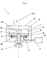
- Fig. 1 shows a first embodiment of a device 1 according to the invention for mounting a cutting ring 2 on a tube 3 with a tube longitudinal axis 4 and formed on an end portion 5 end face 6 (cutting ring 2 and tube 3 are for example in Fig. 2 shown).
- the device 1 has a mounting stub 7, a stop element 18 arranged in a receiving recess 10, a pin 21 for connection to a tool carrier (not shown), a screw 25 for guiding the stop element and a measuring device 9.
- the mounting socket 7 has a central receiving recess 10 for receiving the end portion 5 of the tube 3 and - at least partially - of the end portion 5 can be pushed onto the tube 3 to be mounted cutting ring 2.
- the mounting stub 7 in this embodiment on its underside 11 a cylindrical recess for receiving the pin 21.
- the receiving recess 10 has a longitudinal axis 13, a wall 15 extending in an insertion direction 14, an opening 16 through which the tube 3 can be inserted, and a bottom surface 17.
- the wall 15 is formed in the region of the opening 16 as an inner cone and is formed in the further course in the direction of the bottom 11 as a circular cylinder.
- the bottom surface 17 has a continuous through opening 11 to the underside 11 of the mounting socket 7, which will pass through the screw 25 as a guide means.
- the screw 25 is secured by the pin 21.
- the stop element 18 is cylindrical and also has a passage opening, which is penetrated by the screw 25.
- the oriented in the direction of the opening 16 side of the stop member 18 is the stop surface 35 for the tube 3, in particular its end face 6.
- the side facing away from the opening 16 side of the stop member 18 has a cylindrical recess in which a sensor 22 is arranged, the In this embodiment, a capacitive sensor 22 is. In this case, the surface of the sensor 22 is flush with the surface of the stopper member 18.
- On the side facing away from the opening 16 side of the stop member 18 is further formed around the cylindrical recess concentric groove in which a corrugated spring 24 is arranged.
- the pin 25 serves to connect the mounting socket 7 with a - in Fig. 1 Not shown - tool carrier and for holding the stop member 18 within the receiving recess 10.
- the pin 21 has an internal thread into which the screw 25, the stop element 18 is screwed by cross.
- the pin 21 an RFID unit - not shown - have.
- the measuring device 9 has a arranged in the cylindrical recess of the stop element 18 capacitive sensor 22, in particular distance sensor, as well as connected to the sensor 22, outside the Mounting socket 7 arranged evaluation unit 23.
- the sensor 22 is formed such that its side facing away from the opening 16 is aligned with the bottom surface 17 of the mounting nozzle 7.
- the stop element 18 is arranged in the receiving recess 10 such that it is movable along the screw 25 parallel to the longitudinal axis 13. That is, the arranged in the stop element 18 sensor 22 points in the direction of the bottom surface 17 of the receiving recess 10.
- the wave spring 24 rests on the bottom surface 17, so that the mounting stub 7 and the stopper member 18 are spaced apart to form a gap 26.
- the gap 26 is bounded by the bottom surface 17 and by the surface of the sensor 22 or the side of the stop element 18 facing away from the opening.
- the screw 25 is screwed from the direction of the receiving recess 10, so that the stopper member 18 is held in the above-described position in the receiving recess 10. Due to a predetermined height extent and the spring force of the wave spring 24, the stop element 18 in the axial direction relative to the mounting stub 7 is movable.
- the sensor 22 of the measuring device 9 Since the sensor 22 of the measuring device 9 is arranged such that it delimits the gap 26 on the upper side, the sensor 22 is moved toward the bottom surface 17 when closing the gap 26.
- the closed state of the gap 26 can thus be detected by the sensor 22 and, in particular as a status signal, forwarded to the evaluation unit 23.
- the degree of contact of the end face 6 of the tube 3 with the abutment surface 35 can be measured or ensured that the tube 3 is in a certain position, namely with the end region 5 inserted sufficiently into the receiving recess 10 is to ensure proper assembly of the cutting ring 2.
- the device 1 thus makes it possible, in particular, for the abutment of the end face 6 of the tube 3 to be signaled or measurable on the abutment surface 35 or the degree of the abutment. Based on this, the assembly operation of the cutting ring 2 can be triggered, released or blocked, so that production of a defective cutting ring connection is prevented.
- Fig. 2 is the device 1 according to Fig. 1 shown.
- a pipe 3 is inserted into the mounting stub 7.
- the tube 3 is in the representation shown on the stop surface 35 of the stop element 18, but the stop element 18 has not been moved.
- Fig. 3 is an illustration of the measuring device 9 with the arranged in the mounting piece 7 sensor 22 and the evaluation unit 23.
- the sensor 22 is designed as a capacitive sensor 22, comprising a printed circuit board 27 with two concentric electrodes 28, 29. With the sensor 22 as described the height the gap 26 between the sensor 22 and the bottom surface 17 can be measured so that the closed state of the gap 26 can be determined by the measuring device 9.
- Fig. 4 shows a further embodiment of a device 1 according to the invention for mounting a cutting ring 2.
- the device 1 has in this embodiment, a mounting stub 7, a tool carrier 8 and a measuring device 9.
- no stop element 18 is provided, but the gap 26 is in the form of a plurality of passage channels.
- the mounting stub 7 has a receiving recess 10 for receiving the end region 5 of the tube 3 and the cutting ring 2 which can be pushed onto the end region 5 and mounted on the tube 3.
- the mounting stub 7 on its underside 11, a tool carrier receptacle 12 into which the tool holder 8 is positively inserted.
- the receiving recess 10 is formed as an inner cone and has a longitudinal axis 13, a tapering in an insertion 14 of the tube 3 wall 15, an opening 16 through which the tube 3 is inserted, and a bottom surface 17.
- the bottom surface 17 is at the same time in this embodiment, the stop surface 35 on which the end face 6 of the tube 3 is fully applied.
- the tool carrier 8 has a base body with an insertable into the tool holder receptacle 12 cylindrical projection 19 and an adjoining projecting from the projection 19 annular bearing portion with a pointing in the direction of 19 bearing surface 20.
- the tool carrier an RFID transponder - not shown - have.
- the formed as passageways column 26 are provided.
- the device 1 has two gaps 26 formed as through-channels.
- only one formed as a passage channel gap 26 or a plurality, preferably three, four, five or six formed as passageways column 26 are present.
- the individual formed as passageways column 26 are within the device 1, z. B. in the region of the tool carrier 8 connected to each other, so that they form a continuous flow channel for a fluid, in particular air.
- passages 26 formed as passageways each form independent flow channels, each extending from the stop surface 35 to the outside.
- the passages 26 formed as through-passages are each arranged such that they can be closed by the end face 6 of the tube 3 when the end face 6 bears completely against the stop face 35 of the receiving recess 10. This is particularly the case when the end face 6 and the abutment surface 35 abut one another flat and at the same time the tube longitudinal axis 4 and the longitudinal axis 13 are coaxial with each other.
- the measuring device 9 has in this embodiment, a pump and a pressure sensor - not shown - on.
- Pump and pressure sensor are at the tool carrier-side outlet of the formed as passageways column 26th connected to the outside, so that the pump is fluid-tightly connected to the formed as passageways columns 26.
- an air flow can be generated, which can flow through the column 26.
- a pressure increase can be determined with the pressure sensor when the gaps 26 are at least partially closed by the tube 3.
- the measurable by the measuring device 9 pressure represents the closed state of the column 26 through the pipe 3. From this, the degree of contact of the end face 6 and the complete contact with the stop surface 35 can be determined. From the measurable pressure values, corresponding values thus result for the degree of contact of the tube 3 with the abutment surface 35.
- the respective value can be signaled by means of the status signal or can be measured as a status signal.
- the device according to the invention thus also makes it possible with this embodiment that the system, in particular the degree of the system, the end face 6 of the tube 3 on the stop surface 35 can be detected or measured. Based on this, the assembly operation of the cutting ring 2 can be triggered, released or blocked, so that production of a defective cutting ring connection can be prevented.
- Fig. 5 shows a further embodiment of a device 1 for mounting a cutting ring 2.
- the device 1 has in this embodiment, a mounting stub 7, a tool carrier 8 and a measuring device 9.
- the gap 26 is also formed here in the form of multiple passageways.
- the mounting piece 7 has a receiving recess 10 for receiving the end portion 5 of the tube 3.
- the receiving recess 10 is formed in the end region facing away from the bottom surface as an inner cone and has a longitudinal axis 13, a in an insertion direction 14 of the tube 3 tapered wall 15, an opening 16 through the tube 3 is inserted, and a bottom surface 17.
- the bottom surface 17 is at the same time in this embodiment, the stop surface 35 on which the end face 6 of the tube 3 is fully applied.
- the tool carrier 8 has an RFID transponder - not shown - on.
- the formed as passageways column 26 extending from the stop surface 35 and the bottom surface 17 of the mounting nozzle 7 through this and through the tool carrier 8 through to the outside of the device first
- the passages 26 formed as through-passages are each arranged such that they can be closed by the end face 6 of the tube 3 when the end face 6 bears completely against the stop face 35 of the receiving recess 10.
- the trained as passageways column 26 extend in the pre-assembly 7 in this embodiment, parallel to the longitudinal axis 13.
- the measuring device 9 has in this embodiment, a pump and a flow meter - not shown - on.
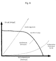
- Fig. 6 is a volume flow-pressure curve for defining limit values in a device 1 according to FIG Fig. 3 shown.
- the limit value represents the pressure up to which a reliable cutting ring connection can be made.
- the diagram shows the pressure curve measurable with the pressure sensor at the pump outlet with completely closed through channels (left), partially closed through channels (middle section) and open through channels (right section). For open passageways, the measured pressure is determined by the hydraulic resistance of the channels.
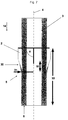
- Fig. 7 is a tube 3 after the assembly process of the cutting ring 2, ie a tube 3 with a cutting ring connection 30 shown.
- the cutting ring connection 30 produced by means of the device 1 according to the invention is a reliable one, in particular with regard to tightness Cutting ring connection 30.
- the decisive for the formation of a cutting ring connection 30 mounting parameters of the device 1 can be predetermined.
- the system of the tube 3 on the stop surface 35 in the mounting socket 7 is sheared as described above.
- the cutting ring 2 is mounted coaxially to the tube longitudinal axis 4, which is expressed at an angle ⁇ of 90 °.
- Other parameters, such. B. penetration depth 31, cutting path 32 and distance of the end face 6 of the tube 3 from the cutting ring 2, limiting pressures or capacitance change limits are stored in the evaluation unit 23 or in the RFID transponder of the tool carrier 8.
- the invention is not limited to the illustrated and described embodiments, but also includes all the same in the context of the invention embodiments. It is expressly emphasized that the exemplary embodiments are not limited to all the features in combination, but rather each individual partial feature may also have an inventive meaning independently of all other partial features. Furthermore, the invention has hitherto not been limited to the combination of features defined in claim 1, but may also be defined by any other combination of certain features of all the individual features disclosed overall. This means that in principle virtually every individual feature of claim 1 can be omitted or replaced by at least one individual feature disclosed elsewhere in the application.
Landscapes
- Engineering & Computer Science (AREA)
- General Engineering & Computer Science (AREA)
- Mechanical Engineering (AREA)
- Measuring Fluid Pressure (AREA)
Abstract
Description
- Die vorliegende Erfindung betrifft eine Vorrichtung sowie ein Verfahren zur Montage eines Schneidrings an einem Rohr, insbesondere zur Ausbildung einer Rohranschlussverbindung für eine lötlose Rohrverschraubung nach ISO EN 8434-1 (Stand 02/2007), gemäß den Oberbegriffen der Ansprüche 1 und 13. Gattungsgemäße Schneidringverschraubungen sind beispielsweise in
DE 40 41 677 A1 undDE 197 09 464 A1 jeweils in spezieller Ausführungsform beschrieben. Im Allgemeinen weist eine Schneidringverschraubung einen Anschlussstutzen, eine auf den Anschlussstutzen aufschraubbare Überwurfmutter sowie einen zwischen Anschlussstutzen und Überwurfmutter angeordneten Schneidring auf. Für die Vormontage eines Schneidrings sind aus dem Stand der Technik unterschiedliche Vorrichtungen bekannt, beispielsweise ausDE 10 2011 053 012 A1 undWO 2013/139641 A1 . - Durch die Vormontage kann in erheblichem Maße die Qualität der Schneidringverbindung beeinflusst werden. Wesentliche, qualitätsbestimmende Faktoren sind der Schneidweg in axialer Richtung, die Schneidtiefe in radialer Richtung, der Abstand zwischen Schneidringoberkante und Stirnseite sowie die Ausrichtung des Rohres innerhalb des Montagestutzens. Es gibt bereits unterschiedliche Maßnahmen zur Absicherung der Prozessqualität der Vormontage, die beispielweise aus
DE 195 26 136 A1 ,DE 36 104 27 A1 undDE 195 75 65 A1 bekannt sind. - Gleichwohl weisen die aus dem Stand der Technik bekannten Vorrichtungen und Verfahren zur Montage von Schneidringen den Nachteil auf, dass keine ausreichende Prozesssicherheit zur Vermeidung von Ausschuss gewährleistet werden kann.
Der vorliegenden Erfindung liegt daher die Aufgabe zu Grunde, die Vormontage eines Schneidrings dahingehend zu verbessern, dass die Ausschussrate verringert wird. - Die vorgenannte Aufgabe durch eine Vorrichtung zur Montage eines Schneidrings mit den Merkmalen des Kennzeichnungsteils von Anspruch 1 gelöst.
Demnach weist die Vorrichtung einen Montagestutzen mit einer Aufnahmevertiefung zur Aufnahme eines Endbereichs eines Rohrs mit einer Stirnfläche sowie eines auf den Endbereich aufschiebbaren und auf das Rohr zu montierenden Schneidrings auf. - Bei der Vormontage wird zunächst die Überwurfmutter und der Schneidring über den Endbereich des Rohres geschoben und anschließend das Rohr in dem Montagestutzen fixiert. Beim Anziehen der Überwurfmutter oder beim Einpressen der Überwurfmutter mit Schneidring in die Aufnahmevertiefung wirkt der Schneidring derart mit der Aufnahmevertiefung, insbesondere dem Innenkonus, des Montagestutzens zusammen, dass eine im vorderen Bereich des Schneidrings ausgebildete Schneidkante verformt und unter Kerbwirkung formschlüssig und/oder kraftschlüssig in das Material des Rohres eindringt. Vorzugsweise weist die Aufnahmevertiefung zumindest teilweise einen sich in Richtung des Schneidrings erweiternden Innenkonus auf.
- Die Vorrichtung ist dadurch gekennzeichnet, dass eine Messeinrichtung vorhanden ist, und dass die Messeinrichtung zum Erfassen der Lage eines in die Aufnahmevertiefung eingeführten Rohres in Bezug auf den Montagestutzen ausgebildet und eingerichtet ist. Mit der Messeinrichtung ist die Lage des Rohres relativ zum Montagestutzen erfassbar. Dadurch wird gewährleistet, dass das Rohr nach dem Eindringen und vor der Montage des Schneidrings in der vordefinierten Lage ist, um eine gewünschte Positionierung des Schneidrings auf dem Endbereich des Rohres zu gewährleisten.
- Dabei ist insbesondere vorgesehen, die Eindringtiefe des Rohres und/oder die axiale Ausrichtung des Rohres in Bezug auf den Vormontagestutzen, insbesondere an mindestens einem Zeitpunkt, zu erfassen. Insbesondere erfolgt das Erfassen mit der Messeinrichtung zumindest unmittelbar vor der Montage des Schneidrings. Bevorzugt wird die Lage des Rohres in Bezug auf den Montagestutzen anhand der Lage der Stirnfläche des Rohres ermittelt. Die Messeinrichtung erfasst zumindest die Lage bzw. Position der Stirnfläche des Rohres.
- Vorzugsweise ist die Messeinrichtung derart ausgebildet, dass der Zeitpunkt der Erfassung der Lage des Rohres in Bezug auf den Montagestutzen, insbesondere die Lage der Stirnfläche des Rohres, beliebig variierbar ist. Somit ist mit der Messeinrichtung zu jedem vorbestimmten oder vorbestimmbaren Zeitpunkt des Montageprozesses erfassbar, wie das Rohr in dem Montagestutzen positioniert ist. Insbesondere ist mit der Messeinrichtung ein kontinuierliches Zustandssignal bezüglich der Position des Rohres erzeugbar.
- Für die Montage eines auf dem Rohr zu montierenden Schneidrings weist die Aufnahmevertiefung des Montagestutzens zweckmäßigerweise eine mittlere Längsachse sowie eine Wandung auf. Dabei ist vorzugsweise vorgesehen, dass die Aufnahmevertiefung zumindest bereichsweise als Innenkonus ausgebildet ist. In einer bevorzugten Ausgestaltung weist die Wandung in einem Bereich eine sich in eine Einführrichtung des in den Montagestutzen einführbaren Rohres verjüngende Konuswandung für die Verformung eines Schneidrings auf, der stirnseitig zumindest eine Schneidkante, dieser gegenüberliegend einen Schneidringanschlag sowie eine Schneidringaußenwandung aufweist. Dabei weist die Schneidringaußenwandung einen konischen, vom Anschlag in Richtung Schneidkante gesehen, sich verjüngenden Bereich auf, der zur Anlage an der Konuswandung der Aufnahmevertiefung ausgebildet ist.
- Gemäß einer ersten Ausgestaltung der Vorrichtung ist vorgesehen, dass in der Aufnahmevertiefung mindestens eine Anschlagfläche vorgesehen ist, und das die Messeinrichtung zum Erfassen zumindest des Anliegens der Stirnfläche des Rohres an der Anschlagfläche ausgebildet ist. Die Anschlagfläche ist zur Anlage der Stirnfläche des Rohres ausgerichtet und angeordnet.
- Dabei ist vorgesehen, dass die Messeinrichtung zur Erfassung entweder des kraftfreien und/oder des mit einer Kraft beaufschlagten Anliegens an der Anschlagfläche ausgebildet ist. "Mit einer Kraft beaufschlagtes Anliegen" bedeutet, dass von der Stirnfläche des Rohres eine Kraft auf die Anschlagfläche bewirkt wird. Mit der Messeinrichtung ist erfassbar, ob das Rohr mit seiner Stirnfläche beispielsweise an der Anschlagfläche vollständig angelegt ist oder nicht.
- Bevorzugt ist die Messeinrichtung zum Erfassen eines Anlageumfangs eingerichtet und ausgebildet. Das bedeutet, mit der Messeinrichtung ist das Ausmaß bzw. der Grad der Anlage der Stirnfläche des Rohres an der Anschlagfläche der Aufnahmevertiefung erfassbar ist. Beispielsweise ist der Anlageumfang zu Werten von 0 bis 100% bestimmbar, wobei 0% überhaupt keine Anlage und 100% die vollständige Anlage der Stirnfläche an der Anschlagfläche darstellt.
- Bei vollständiger Anlage der Stirnfläche des Rohres an der Anschlagfläche kann die Montage freigegeben werden, wobei durch das vollständige Anliegen der Stirnfläche sichergestellt ist, dass sich das Rohr in einer vordefinierten Position befindet und der Schneidring somit lagerichtig montiert wird.
- Um insbesondere die Position der Stirnfläche des Rohres genau erfassen zu können, ist gemäß einer bevorzugten Ausgestaltung vorgesehen, dass der Montagestutzen mindestens einen Spalt aufweist, dass der Spalt mit einem in die Aufnahmevertiefung eingeführten Rohr, insbesondere mit der Stirnfläche, mittelbar oder unmittelbar zumindest teilweise verschließbar ist, und dass die Messeinrichtung zur Erfassung eines Schließzustandes des Spaltes ausgebildet ist. Über den Schließzustand des Spaltes kann auf die Lage des Rohres in Bezug auf den Montagestutzen geschlossen werden.
- Der Spalt wird mittels des Rohres vollständig verschlossen, wenn die Stirnfläche des Rohres und die Anschlagfläche der Aufnahmevertiefung vollständig aneinander anliegen und gleichzeitig Rohrlängsachse und eine Längsachse der Aufnahmevertiefung koaxial zueinander sind. Der Spalt wird folglich genau dann verschlossen, wenn die Stirnfläche rechtwinklig zur Längsachse der Aufnahmevertiefung und die Anschlagfläche rechtwinklig zur Längsachse des Rohres orientiert ist und die beiden Achsen koaxial zueinander sind.
- Der Schließzustand des Spaltes beschreibt das Ausmaß bzw. den Grad, mit dem der Spalt verschlossen ist. Beispielsweise ist der Schließzustand zu Werten von 0 bis 100% bestimmbar, wobei 0% bedeutet, dass der Spalt nicht verschlossen ist, und wobei 100% bedeutet, dass der Spalt vollständig geschlossen ist.
- Dementsprechend ist mit der Messeinrichtung erfassbar, ob der Spalt in geöffnetem Zustand, in geschlossenem Zustand oder in teilweise geöffnetem bzw. geschlossenem Zustand ist und inwieweit, d. h. zu welchem Grad, z. B. von 0 bis 100%, der ausgesparte Bereich geöffnet bzw. verschlossen ist. Beispielsweise ist die gewünschte Lage des Rohres nicht bei vollständig geschlossenem Spalt, sondern bei zu 80% geschlossenem Spalt erreicht.
- Mit der Messeinrichtung ist somit der Schließzustand des ausgesparten Bereichs, insbesondere wertmäßig, erfassbar und beispielsweise ein Zustandssignal diesbezüglich, insbesondere in einem Wertebereich von 0 bis 100%, generierbar.
- Das Zustandssignal repräsentiert die Lage des Rohres in Bezug auf den Montagestutzen.
- Eine bevorzugte Ausgestaltung der Vorrichtung sieht vor, dass die Messeinrichtung einen Abstandssensor aufweist, insbesondere dass der Abstandssensor ein kapazitiver Sensor ist.
- Es ist auch vorgesehen, dass mit dem Abstandssensor der Schließzustand des Spaltes, insbesondere die Höhe des Spaltes, erfasst wird. Der Abstandssensor ist dazu dem Spalt zugeordnet und erfasst dessen Schließzustand, beispielsweise zumindest zu einem Zeitpunkt vor der Montage des Schneidrings. Der von der Messeinrichtung messbare Abstand, repräsentiert dabei den Schließzustand des Spalts bzw. den Grad der Anlage der Stirnfläche an der Anschlagfläche. Somit ist jedem Abstandswert ein Wert für den Schließzustand bzw. den Grad der Anlage des Rohres zugeordnet bzw. zuordenbar. Wenn der Spalt durch entsprechendes Anpressen des Rohres vollständig geschlossen ist, d. h. wenn die Stirnfläche der Rohr vollständig an der Anschlagfläche anliegt, ist der gemessene Abstand gleich Null oder annähernd Null. Der Abstand steigt, je weiter der Grad der Anlage des Rohres abnimmt. Bei vollständig geöffnetem Spalt, bzw. wenn das Rohr gar nicht an der Anschlagfläche anliegt, ist lediglich ein Ausgangswert für den Abstand messbar. Aus den Abstandswerten ergibt sich entsprechend der Wertebereich für den Schließzustand bzw. für den Grad der Anlage des Rohres, auf Basis dessen beispielsweise ein Zustandssignal erzeugbar ist.
- Vorzugsweise ist der Abstandssensor ein kapazitiver Sensor mit einer Leiterplatte mit zwei konzentrischen Elektroden. Besonders bevorzugt bildet der kapazitive Sensor den frequenzbestimmenden Teil eines Schwingkreises.
- Es hat sich zudem als vorteilhaft herausgestellt, wenn gemäß einer Weiterbildung vorgesehen ist, in der Aufnahmevertiefung ein Anschlagelement gehalten ist, dass der Spalt zwischen Anschlagelement und Montagestutzen, insbesondere zwischen Anschlagelement und Bodenfläche der Aufnahmevertiefung, ausgebildet ist, und dass der Schließzustand des Spaltes durch Krafteinwirkung des Rohres auf das Anschlagelement beeinflussbar ist. Das Anschlagelement ist beispielsweise innerhalb der Aufnahmevertiefung derart gehalten, dass seine in Richtung des Rohres gewandte Oberfläche als Anschlagfläche für die Stirnfläche des Rohres dient. Dabei ist das Anschlagelement mittels des Rohres entlang der Längsachse des Montagestutzens verschiebbar gehalten.
- Der Spalt ist vorzugsweise zwischen dem Anschlagelement und der Bodenfläche der Aufnahmevertiefung ausgebildet und durch Verschiebung des Anschlagelements mittels der Rohrleitung verschließbar. Das Rohr ist insbesondere dann in der vorbestimmten Lage zur Montage des Schneidrings, wenn das Rohr mit seiner Stirnfläche vollständig unter Wirkung einer Kraft an der Anschlagfläche auf dem Anschlagelement anliegt und der Spalt vollständig oder zu einem bestimmten Anteil geschlossen ist.
- Ferner ist gemäß einer Ausgestaltung vorteilhaft, wenn das Anschlagelement unter Wirkung einer Feder, insbesondere einer Wellfeder, in der Aufnahmevertiefung gehalten ist. Vorzugsweise weist das Anschlagelement eine Öffnung auf, die von einem Führungsmittel, z. B. einem Bolzen oder einer Schraube, durchtreten wird, so dass das Anschlagelement parallel zur Längsachse des Montagestutzens entlang des Führungsmittels bewegbar ist. Zwischen der Bodenfläche der Aufnahmevertiefung und dem Anschlagelement ist die Feder angeordnet, die das Anschlagelement von der Bodenfläche beabstandet und dadurch den Spalt ausbildet. Eine Bewegung des Anschlagelements - durch das Rohr - bei der der Spalt geschlossen wird, erfolgt stets entgegen der Kraft der Feder. Beim Einführen des Rohres wird die Feder komprimiert und der Spalt - zumindest teilweise - geschlossen.
- Die Kraftübertragung von der Feder auf das Anschlagelement wird insbesondere verbessert, wenn die Feder eine Wellfeder ist.
- Eine Ausgestaltung der Vorrichtung sieht vor, dass die Messeinrichtung mindestens eine Pumpe und einen Drucksensor oder ein Durchflussmesser aufweist. Das Einführen des Rohres in die Aufnahmevertiefung führt beispielsweise zur Änderung eines durch die Pumpe hervorgerufenen Druckes, der mittels des Drucksensors erfasst wird, oder einer Änderung der Durchflussrate, die mit dem Durchflussmesser erfasst wird, wodurch auf die Position bzw. Lage des Rohres geschlossen werden kann.
- Eine bevorzugte Weiterbildung sieht vor, der Spalt als mindestens ein Durchgangskanal ausgestaltet ist, der sich ausgehend von einer Bodenfläche der Aufnahmevertiefung durch den Montagestutzen nach außen erstreckt, wobei der Durchgangskanal derart ausgebildet ist, dass er durch die Stirnseite des in die Aufnahmevertiefung eingeführten Rohres verschließbar ist. Dies ist insbesondere dann der Fall, wenn die Stirnfläche des Rohres und die Anschlagfläche aneinander anliegen und gleichzeitig die Rohrlängsachse und die Längsachse der Aufnahmevertiefung koaxial zueinander sind. Die Bodenfläche der Aufnahmevertiefung ist dabei die Anschlagfläche für die Stirnfläche des Rohres.
Die Messeinrichtung weist bei dieser Ausgestaltung eine Pumpe und einen Drucksensor oder einen Durchflussmesser auf. Die Pumpe steht mit dem Durchgangskanal in Verbindung, so dass mit der Pumpe eine Strömung erzeugbar ist, die den Durchgangskanal durchströmen kann. Dabei ist mit dem Drucksensor ein Druckanstieg bzw. mit dem Durchflussmesser eine reduzierte Durchflussrate ermittelbar, wenn der Durchgangskanal durch das Rohr zumindest teilweise verschlossen ist. Ist der Durchgangskanal durch die Stirnseite des Rohres verschlossen, ist dessen Lage bekannt. - Der von der Messeinrichtung messbare Druck, z. B. am Ausgang der Pumpe, bzw. die reduzierte Durchflussrate repräsentiert den Schließzustand des Durchgangskanals bzw. den Grad der Anlage der Stirnfläche des Rohres an der Anschlagfläche. Somit ist jedem Druckwert bzw. jeder Durchflussrate ein Wert für den Schließzustand bzw. den Grad der Anlage des Rohres zugeordnet bzw. zuordenbar. Wenn der Durchgangskanal durch das Rohr vollständig verschlossen ist bzw. wenn die Stirnfläche des Rohres vollständig an der Anschlagfläche anliegt, ist ein maximaler Druck messbar bzw. eine minimale Durchflussrate. Der Druck nimmt ab bzw. die Durchflussrate zu, je weiter der Durchgangskanal geöffnet ist bzw. je weiter der Grad der Anlage des Rohres abnimmt. Bei vollständig geöffnetem Durchgangskanal bzw. wenn das Rohr gar nicht an der Anschlagfläche anliegt, ist nur ein Minimaldruck bzw. ein maximaler Durchfluss messbar. Aus den messbaren Druckwerten bzw. Durchflussraten ergibt sich entsprechend der Wertebereich für den Schließzustand bzw. für den Grad der Anlage des Rohres, auf Basis dessen insbesondere ein Zustandssignal erzeugbar ist.
- Gemäß einer weiteren Ausgestaltung ist vorgesehen, dass die Messeinrichtung ein Zustandssignal erzeugt, und dass die Montage des Schneidrings an dem Rohr auf Basis des Zustandssignals gesteuert wird, insbesondere dass ein Steuergerät vorhanden ist, und dass Zustandssignal mit dem Steuergerät verarbeitbar und die Montage mit dem Steuergerät gesteuert wird. Die Steuerung beinhaltet insbesondere, dass der Montagevorgang automatisiert in Gang setzbar und/oder für eine die Vorrichtung bedienende Bedienperson freigebbar ist, wenn der Spalt in geschlossenem Zustand ist, oder der Montagevorgang blockierbar ist, wenn der Spalt in geöffnetem Zustand oder ungleichmäßig geschlossen ist.
- Dies bewirkt, dass der Montagevorgang nur dann ausführbar oder auslösbar ist, wenn das Rohr mit seiner Stirnfläche vollständig an der Anschlagfläche in der Aufnahmevertiefung im Montagestutzen anliegt, d. h. wenn das Rohr derart positioniert ist, dass eine ordnungsmäße Schneidringverbindung herstellbar ist.
- Dementsprechend ist sichergestellt, dass der Montagevorgang blockiert ist, wenn das Rohr mit seiner Stirnfläche nicht ausreichend an der Anschlagfläche anliegt, d. h. wenn das Rohr derart positioniert ist, dass der Montagevorgang wohl einen Ausschuss ergeben würde.
- Zweckmäßigerweise ist die Messeinrichtung mit einer Auswerteeinheit verbunden. Mit der Auswerteeinheit ist das Zustandssignal auswertbar und darauf basierend ein Steuersignal erzeugbar. Das Steuersignal wiederrum ist dem Steuergerät zuführbar, so dass wie bereits beschrieben mit dem Steuergerät das Zustandssignal der Messeinrichtung verarbeitbar ist.
- Gemäß einer weiteren Ausgestaltung der Vorrichtung ist vorgesehen, dass basierend auf dem Zustandssignal ein optisches und/oder akustisches Informationssignal für eine Bedienperson bezüglich der Anlage der Stirnfläche des Rohres an der Anschlagfläche erzeugbar ist. Dies kann beispielsweise ein Warnton oder eine Warnlicht sein, wenn das Rohr nicht ausreichend bzw. teilweise an der Anschlagfläche anliegt. Des Weiteren kann das Informationssignal ein Freigabeton oder -licht sein, mittels dem signalisierbar ist, dass der Montagevorgang ausgelöst werden kann, wenn die Stirnfläche des Rohres vollständig an der Anschlagfläche anliegt.
- Gemäß einer weiteren Ausgestaltung weist die Vorrichtung einen Werkzeugträger auf, auf dem der Montagestutzen lagerbar ist. Der Werkzeugträger weist eine Einrichtung zur Datenbereitstellung, insbesondere einen RFID-Transponder oder Barcode, auf. Mit der Einrichtung zur Datenbereitstellung ist beispielsweise der auf dem Werkzeugträger befindliche Montagestutzen identifizierbar und/oder es sind Parameter für den durchzuführenden Montagevorgang auslesbar.
- Besonders bevorzugt ist mit der erfindungsgemäßen Vorrichtung, z. B. mit der Messeinheit und/oder der Auswerteeinheit, ein binäres Signal erzeugbar, sobald der Druck am Ausgang der Pumpe einen bestimmbaren Grenzwert übersteigt. Dieser Grenzwert repräsentiert einen ausreichenden Schließzustand bzw. einen ausreichenden Grad der Anlage der Stirnfläche an der Anschlagfläche, auf Basis dessen eine ordnungsgemäße Schneidringverbindung herstellbar ist.
- Zweckmäßigerweise ist der Grenzwert in der Steuereinheit oder in der Auswerteeinheit oder in der Einrichtung zur Datenbereitstellung hinterlegt. Gemäß einer vorteilhaften Weiterbildung ist vorgesehen, dass, z. B. mit der Steuereinheit oder mit der Auswerteeinheit, eine Rechteckschwingung generierbar ist, deren Frequenz stetig von der axialen Höhenerstreckung des Spalts abhängt. Die Frequenz ist von einem Mikroprozessor auswertbar.
- Vorzugsweise ist mit dem Mikroprozessor jedem Frequenzwert ein Kennwert zuordenbar, der die Höhenerstreckung des Spalts repräsentiert, so dass ein Grenzwert für die Freigabe des Montageprozesses bestimmbar ist. Besonders bevorzugt ist mit der erfindungsgemäßen Vorrichtung, z. B. mit der Steuereinheit oder mit der mit der Auswerteeinheit, ein binäres Signal erzeugbar, sobald die Frequenz den Grenzwert übersteigt. Der Grenzwert repräsentiert dabei einen ausreichenden Schließzustand bzw. einen ausreichenden Grad der Anlage der Stirnfläche an der Anschlagfläche. Zweckmäßigerweise ist der Grenzwert in der Steuereinheit oder in der Auswerteeinheit hinterlegt oder mit der Einrichtung zur Datenbereitstellung identifizierbar.
- Zusätzlich oder alternativ ist gemäß einer Weiterbildung die Vorrichtung derart ausgebildet und eingerichtet, dass mit der Messeinrichtung die Anpresskraft des Rohres gegen die Anschlagfläche messbar ist. Dabei repräsentiert die Anpresskraft den Grad der Anlage der Stirnfläche an der Anschlagfläche, wobei jeder Wert der Anpresskraft einen Wert für den Grad der Anlage darstellt. Über die Anpresskraft ist somit ebenfalls wie beschrieben das Zustandssignal erzeugbar.
- Vorteilhaft bei der erfindungsgemäßen Vorrichtung ist, dass mit dem Zustandssignal zumindest die vollständige Anlage, d. h. einen Montageerfolg repräsentierende Positionierung, der Stirnfläche signalisierbar ist, so dass der Montagevorgang des Schneidrings an der Rohr basierend auf dem Zustandssignal erfolgen, insbesondere gesteuert werden kann. Dadurch kann die Produktion von Rohren mit einer den Anforderungen an die Dichtigkeit von Hochdruckhydraulikverbindungen entsprechende Schneidringverbindung sichergestellt werden und ein Ausschuss aufgrund von unzureichend angeordneten Rohren verhindert werden.
- Die erfindungsgemäße Aufgabe wird zudem durch ein Verfahren zur Montage eines Schneidrings an einem Rohr mit den kennzeichnenden Merkmalen von Anspruch 13 gelöst. Demnach weist das Verfahren folgende Verfahrensschritte auf:
- Aufstecken eines zu montierenden Schneidrings, aufweisend zumindest eine Schneidkante, auf einen Endbereich eines Rohres mit einer Rohrlängsachse und einer am Endbereich ausgebildeten Stirnfläche,
- Einführen des Endbereichs mitsamt dem Schneidring in eine Aufnahmevertiefung eines Montagestutzens in einer Einführrichtung, wobei die Aufnahmevertiefung eine mittlere Längsachse und eine Wandung aufweist,
- Beaufschlagen des Schneidrings mit einer, vorzugsweise von einer Presseinrichtung erzeugten, Montagekraft, so dass die Schneidkante des Schneidrings in das Rohr eindringt,
- wobei vor dem Beaufschlagen des Schneidrings mit einer Montagekraft ein Erfassen einer Lage des Rohres in Bezug auf den Montagestutzen mit einer Messeinrichtung erfolgt.
- Eine Ausgestaltung des Verfahrens sieht vor, dass mit der Messeinrichtung die Anlage der Stirnfläche der Rohrleitung an einer Anschlagsfläche in der Aufnahmevertiefung erfasst wird. Die Anlage der Stirnfläche des Rohres an der Anschlagsfläche wird an zumindest einem Zeitpunkt gemessen. Vorzugsweise wird die Anlage der Stirnfläche zu beliebig variierbaren Zeitpunkten erfasst. Somit kann mit der Messeinrichtung zu jedem vorbestimmten oder vorbestimmbaren Zeitpunkt des Montageprozesses gemessen werden, ob das Rohr mit seiner Stirnfläche an der Anschlagfläche vollständig anliegt oder nicht.
- Insbesondere wird mit der Messeinrichtung ein kontinuierliches Zustandssignal bezüglich der Anlage der Stirnfläche erzeugt, insbesondere über einen bestimmten Zeitraum, z. B. während des Pressens.
- Gemäß einer bevorzugten Ausgestaltung des Verfahrens wird mit der Messeinrichtung auch ein Anlageumfang gemessen. Das bedeutet, die Messeinrichtung erfasst das Ausmaß bzw. den Grad der Anlage der Stirnfläche des Rohres an der Anschlagfläche. Beispielsweise wird der Anlageumfang zu Werten von 0 bis 100% bestimmt, wobei 0% überhaupt keine Anlage und 100% die vollständige Anlage der Stirnfläche an der Anschlagfläche darstellt.
- Ferner hat sich gemäß einer Ausgestaltung des Verfahrens aus vorteilhaft erwiesen, wenn vorgesehen ist, dass das Beaufschlagen des Schneidrings mit einer Montagekraft freigegeben wird, wenn die Messeinrichtung ein vollständiges Anliegen der Stirnfläche des Rohres an einer Anschlagfläche in der Ausnahmevertiefung erfasst. Dadurch wird sichergestellt, dass das Rohr und der Schneidring der bei Montage in der ordnungsgemäßen Position sind und richtig montiert werden.
- Insbesondere ist vorgesehen, dass ein Zustandssignal von der Messeinrichtung erzeugt wird und, z. B. mit einem Steuergerät, verarbeitet wird, wobei der Montagevorgang des Schneidrings an dem Rohr auf Basis des Zustandssignals gesteuert wird. Die Steuerung beinhaltet insbesondere, dass der Montagevorgang automatisiert in Gang gesetzt und/oder für eine die Vorrichtung bedienende Bedienperson freigegeben wird, wenn die Stirnfläche der Rohr vollständig an der Anschlagfläche der Aufnahmevertiefung im Montagestutzen anliegt, oder der Montagevorgang blockiert wird, wenn dies nicht der Fall ist.
Dadurch wird der Montagevorgang nur dann ausgeführt oder ausgelöst, wenn das Rohr derart positioniert wird, dass der Montagevorgang eine zuverlässige Schneidringverbindung erzeugt. Dementsprechend ist sichergestellt, dass der Montagevorgang blockiert wird, wenn das Rohr mit seiner Stirnfläche nicht ausreichend an der Anschlagfläche angelegt wird. - Gemäß einer weiteren Ausgestaltung des Verfahrens ist vorgesehen, dass die Messeinrichtung die Anlage der Stirnfläche des Rohres an der Anschlagfläche mit einem kapazitiven Sensor erfasst. Auf Basis der gemessenen Werte wird insbesondere ein Zustandssignal für den Grad der Anlage des Rohres erzeugt.
- Gemäß einer alternativen Ausgestaltung des Verfahrens ist vorgesehen, dass die Anlage der Stirnfläche des Rohres an der Anschlagfläche als Änderung eines mit einer Pumpe erzeugten Druckes mit der Messeinrichtung, insbesondere mit einem Drucksensor, erfasst wird.
- Vorzugsweise ist dabei vorgesehen, dass die Pumpe eine Luftströmung in einem Durchgangskanal, der sich ausgehend von der Anschlagfläche der Aufnahmevertiefung durch den Montagestutzen nach außen erstreckt, erzeugt. Der Durchgangskanal kann durch die Stirnfläche des Rohres verschlossen werden, wenn die Stirnfläche vollständig an die Anschlagfläche angelegt wird. Dies ist insbesondere dann der Fall, wenn die Stirnfläche des Rohres und die Anschlagfläche in der Aufnahmevertiefung aneinander anliegen und gleichzeitig die Rohrlängsachse und die Längsachse der Aufnahmevertiefung bzw. des Montagestutzens koaxial zueinander sind.
- Der von der Messeinrichtung gemessene Druck, z. B. am Ausgang der Pumpe, repräsentiert den Schließzustand des Durchgangskanals bzw. den Grad der Anlage der Stirnfläche an der Anschlagfläche.
- Auf diese Weise wird ermöglicht, dass das Rohr im Montagestutzen korrekt ausgerichtet werden kann, bevor der Montagevorgang ausgelöst wird. Dadurch wird mit dem erfindungsgemäßen Verfahren die Herstellung von Ausschuss, z. B. durch schief im Montagestutzen angelegte Rohre, vermieden.
- Weitere vorteilhafte Ausbildungen der Erfindung sind in den Unteransprüchen enthalten. Anhand der in den beiliegenden Zeichnungen dargestellten Ausführungsbeispiele wird die Erfindung genauer erläutert. Es zeigen:
- Fig. 1
- eine erste Ausführungsform einer erfindungsgemäßen Vorrichtung in schematischer Schnittdarstellung,
- Fig. 2
- die Vorrichtung gemäß
Fig. 1 mit eingeführtem Rohr, - Fig. 3
- einen Sensor der Vorrichtung gemäß
Fig. 1 in Aufsicht, - Fig. 4
- eine zweite Ausführungsform einer erfindungsgemäßen Vorrichtung in schematischer Schnittdarstellung,
- Fig. 5
- eine Ausführungsform einer erfindungsgemäßen Vorrichtung in schematischer Schnittdarstellung,
- Fig. 6
- eine Volumenstrom-Druck-Kennlinie zur Vorrichtung gemäß
Fig. 4 undFig. 5 , - Fig. 7
- eine erfindungsgemäß hergestellte Schneidringverbindung in schematischer Schnittdarstellung, und
- Fig. 8
- ein schematischer Ablauf eines Ausführungsbeispiels des Verfahrens.
- In den verschiedenen Figuren der Zeichnung sind gleiche Teile stets mit denselben Bezugszeichen versehen.
- Zu der anschließenden Beschreibung wird beansprucht, dass die Erfindung nicht auf die Ausführungsbeispiele und dabei nicht auf alle oder mehrere Merkmale von beschriebenen Merkmalskombinationen beschränkt ist, vielmehr ist jedes einzelne Teilmerkmal des/jedes Ausführungsbeispiels auch losgelöst von allen anderen im Zusammenhang damit beschriebenen Teilmerkmalen für sich und auch in Kombination mit beliebigen Merkmalen eines anderen Ausführungsbeispiels von Bedeutung für den Gegenstand der Erfindung.
-
Fig. 1 zeigt ein erstes Ausführungsbeispiel einer erfindungsgemäßen Vorrichtung 1 zur Montage eines Schneidrings 2 an einem Rohr 3 mit einer Rohrlängsachse 4 und einer an einem Endbereich 5 ausgebildeten Stirnfläche 6 (Schneidring 2 und Rohr 3 sind beispielsweise inFig. 2 dargestellt). Die Vorrichtung 1 weist einen Montagestutzen 7, ein in einer Aufnahmevertiefung 10 angeordnetes Anschlagelement 18, einen Zapfen 21 zur Verbindung mit einem Werkzeugträger (nicht dargestellt), eine Schraube 25 zur Führung des Anschlagelements sowie eine Messeinrichtung 9 auf. - Der Montagestutzen 7 weist eine zentrale Aufnahmevertiefung 10 zur Aufnahme des Endbereichs 5 des Rohres 3 sowie - zumindest teilweise - des auf den Endbereich 5 aufschiebbaren und auf dem Rohr 3 zu montierenden Schneidrings 2 auf. Zudem weist der Montagestutzen 7 bei diesem Ausführungsbeispiel an seiner Unterseite 11 eine zylindrische Aussparung zur Aufnahme des Zapfens 21 auf.
- Die Aufnahmevertiefung 10 weist eine Längsachse 13, eine sich in eine Einführrichtung 14 erstreckende Wandung 15, eine Öffnung 16, durch die das Rohr 3 einführbar ist, sowie eine Bodenfläche 17 auf. Die Wandung 15 ist im Bereich der Öffnung 16 als Innenkonus ausgebildet und ist im weiteren Verlauf in Richtung der Unterseite 11 als Kreiszylinder ausgebildet. Die Bodenfläche 17 weist eine bis zur Unterseite 11 des Montagestutzens 7 durchgehende Durchgangsöffnung auf, die von der Schraube 25 als Führungsmittel durchtreten wird. Die Schraube 25 ist mittels des Zapfens 21 gesichert.
- Das Anschlagelement 18 ist zylindrisch ausgebildet und weist ebenfalls eine Durchgangsöffnung auf, die von der Schraube 25 durchtreten wird. Die in Richtung der Öffnung 16 orientierte Seite des Anschlagselements 18 ist die Anschlagfläche 35 für das Rohr 3, insbesondere dessen Stirnseite 6. Die von der Öffnung 16 abgewandte Seite des Anschlagselements 18 weist eine zylindrische Ausnehmung auf, in der ein Sensor 22 angeordnet ist, der bei diesem Ausführungsbeispiel ein kapazitiver Sensor 22 ist. Dabei fluchtet die Oberfläche des Sensors 22 mit der Oberfläche des Anschlagelements 18. An der von der Öffnung 16 abgewandten Seite des Anschlagelements 18 ist des Weiteren eine um die zylindrische Ausnehmung konzentrisch verlaufende Nut ausgebildet, in der eine Wellfeder 24 angeordnet ist.
- Der Zapfen 25 dient zur Verbindung des Montagestutzens 7 mit einem - in
Fig. 1 nicht dargestellten - Werkzeugträger sowie zur Halterung des Anschlagelements 18 innerhalb der Aufnahmevertiefung 10. Hierzu weist der Zapfen 21 ein Innengewinde auf, in das die Schraube 25 das Anschlagelement 18 durchgreifend einschraubbar ist. Außerdem kann der Zapfen 21 eine RFID-Einheit - nicht dargestellt - aufweisen. Die Messeinrichtung 9 weist einen in der zylindrischen Ausnehmung des Anschlagelements 18 angeordneten kapazitiven Sensor 22, insbesondere Abstandssensor, sowie eine mit dem Sensor 22 verbundene, außerhalb des Montagestutzens 7 angeordnete Auswerteeinheit 23 auf. Zweckmäßigerweise ist der Sensor 22 derart ausgebildet, dass seine von der Öffnung 16 abgewandte Seite mit der Bodenfläche 17 des Montagestutzens 7 fluchtet. - Im montierten Zustand der Vorrichtung 1 ist das Anschlagelement 18 derart in der Aufnahmevertiefung 10 angeordnet, dass es entlang der Schraube 25 parallel zur Längsachse 13 bewegbar ist. Das heißt, der im Anschlagelement 18 angeordnete Sensor 22 weist in Richtung Bodenfläche 17 der Aufnahmevertiefung 10. Dabei liegt die Wellfeder 24 auf der Bodenfläche 17 auf, so dass der Montagestutzen 7 und das Anschlagelement 18 unter Ausbildung eines Spalts 26 voneinander beabstandet sind. Der Spalt 26 ist dabei von der Bodenfläche 17 sowie von der Oberfläche des Sensors 22 bzw. der von der Öffnung abgewandten Seite des Anschlagelements 18 begrenzt.
- Auf der Unterseite 11 des Montagestutzens ist der Zapfen 21 eingesetzt, wobei die jeweiligen Durchgangsöffnungen in dem Montagestutzen 7, im Anschlagelement 18 und im Zapfen 21 miteinander fluchten. In die Durchgangskanäle ist die Schraube 25 aus Richtung der Aufnahmevertiefung 10 eingeschraubt, so dass das Anschlagelement 18 in der vorstehend beschriebenen Position in der Aufnahmevertiefung 10 gehalten ist. Aufgrund einer vorbestimmten Höhenerstreckung sowie der Federkraft der Wellfeder 24 ist das Anschlagelement 18 in axialer Richtung relativ zum Montagestutzen 7 bewegbar.
- Aufgrund dieser Ausgestaltung ist durch Anpressen des Rohres 3 gegen die Anschlagfläche 35 der Spalt 26, insbesondere dessen axiale Höhenerstreckung, beeinflussbar, insbesondere verringerbar. Dadurch ist der Spalt 26 bei Aufwendung einer bestimmten Anpresskraft mittelbar verschließbar. Der Spalt 26 ist nur dann vollständig verschließbar, wenn die Stirnfläche 6 des Rohres 3 und die Anschlagfläche 35 aneinander anliegen und gleichzeitig die Rohrlängsachse 4 und die Längsachse 13 der Aufnahmevertiefung 10 koaxial zueinander sind. In dieser Lage des Rohres 3 relativ zum Montagestutzen 7 ist dann gewährleistet, dass der Schneidring 2 ordnungsgemäß montiert werden kann.
- Da der Sensor 22 der Messeinrichtung 9 derart angeordnet ist, dass er den Spalt 26 oberseitig begrenzt, wird der Sensor 22 beim Verschließen des Spalts 26 auf die Bodenfläche 17 zu bewegt. Mit dem Sensor 22 ist somit der Schließzustand des Spalts 26 erfassbar und, insbesondere als Zustandssignal, an die Auswerteeinheit 23 weiterleitbar. Dadurch ist auf Basis des Schließzustands des Spalts 26 der Grad der Anlage der Stirnfläche 6 des Rohres 3 an der Anschlagfläche 35 messbar bzw. sichergestellt, dass sich das Rohr 3 in einer bestimmten Position befindet, nämlich mit dem Endbereich 5 ausreichend in die Aufnahmevertiefung 10 eingeschoben ist, um eine ordnungsgemäße Montage des Schneidrings 2 zu gewährleisten.
- Die Vorrichtung 1 ermöglicht somit insbesondere, dass die Anlage der Stirnfläche 6 des Rohres 3 an der Anschlagfläche 35 bzw. der Grad der Anlage signalisierbar bzw. messbar ist. Basierend darauf kann der Montagevorgang des Schneidrings 2 ausgelöst, freigegeben oder blockiert werden, so dass eine Herstellung einer mangelhaften Schneidringverbindung verhindert wird.
- In
Fig. 2 ist die Vorrichtung 1 gemäßFig. 1 dargestellt. InFig. 2 ist ein Rohr 3 in den Montagestutzen 7 eingeführt. Das Rohr 3 liegt in der gezeigten Darstellung an der Anschlagfläche 35 des Anschlagelementes 18 an, allerdings ist das Anschlagelement 18 noch nicht bewegt worden. Auf den Endbereich 5 sind der Schneidring 2 und eine Überwurfmutter 34 aufgeschoben. -
Fig. 3 ist eine Darstellung der Messeinrichtung 9 mit dem im Montagestutzen 7 angeordneten Sensor 22 und der Auswerteeinheit 23. Der Sensor 22 ist als kapazitiver Sensor 22 ausgebildet, aufweisend eine Leiterplatte 27 mit zwei konzentrischen Elektroden 28, 29. Mit dem Sensor 22 ist wie beschrieben die Höhe des Spaltes 26 zwischen Sensor 22 und Bodenfläche 17 messbar, so dass von der Messeinrichtung 9 der Schließzustand des Spalts 26 ermittelbar ist. -
Fig. 4 zeigt ein weiteres Ausführungsbeispiel einer erfindungsgemäßen Vorrichtung 1 zur Montage eines Schneidrings 2. Die Vorrichtung 1 weist in diesem Ausführungsbeispiel einen Montagestutzen 7, einen Werkzeugträger 8 sowie eine Messeinrichtung 9 auf. Im Unterschied zum vorangegangenen Ausführungsbeispiel ist jedoch kein Anschlagelement 18 vorgesehen, sondern der Spalt 26 ist in Form von mehreren Durchgangskanälen ausgebildet. - Der Montagestutzen 7 weist eine Aufnahmevertiefung 10 zur Aufnahme des Endbereiches 5 des Rohres 3 sowie des auf den Endbereich 5 aufschiebbaren und auf dem Rohr 3 zu montierenden Schneidrings 2 auf. Zudem weist der Montagestutzen 7 an seiner Unterseite 11 eine Werkzeugträgeraufnahme 12 auf, in die der Werkzeugträger 8 formschlüssig einführbar ist.
- Die Aufnahmevertiefung 10 ist als Innenkonus ausgebildet und weist eine Längsachse 13, eine sich in eine Einführrichtung 14 des Rohres 3 verjüngende Wandung 15, eine Öffnung 16, durch die das Rohr 3 einführbar ist, sowie eine Bodenfläche 17 auf. Die Bodenfläche 17 ist bei diesem Ausführungsbeispiel gleichzeitig die Anschlagfläche 35, an der die Stirnfläche 6 des Rohres 3 vollständig anlegbar ist.
- Der Werkzeugträger 8 weist einen Grundkörper mit einem in die Werkzeugträgeraufnahme 12 einführbaren zylindrischen Vorsprung 19 sowie einem sich daran anschließenden vom Vorsprung 19 abstehenden ringförmigen Lagerabschnitt mit einer in Richtung Vorsprung 19 weisenden Lagerfläche 20 auf. Außerdem kann der Werkzeugträger eine RFID-Transponder - nicht dargestellt - aufweisen.
- Wesentlich bei diesem Ausführungsbeispiel ist, dass die als Durchgangskanäle ausgebildeten Spalte 26 vorgesehen sind. Die Vorrichtung 1 weist im dargestellten Beispiel zwei als Durchgangskanäle ausgebildete Spalte 26 auf. Es liegt jedoch auch im Rahmen der Erfindung, dass lediglich ein als Durchgangskanal ausgebildeter Spalt 26 oder eine Mehrzahl, vorzugsweise drei, vier, fünf oder sechs als Durchgangskanäle ausgebildete Spalte 26 vorhanden sind.
- Die als Durchgangskanäle ausgebildeten Spalte 26 erstrecken sich von der Anschlagfläche 35 bzw. der Bodenfläche 17 des Montagestutzens 7 durch diesen sowie durch den Werkzeugträger 8 hindurch bis zur Außenseite der Vorrichtung 1.
- Die einzelnen als Durchgangskanäle ausgebildeten Spalte 26 sind innerhalb der Vorrichtung 1, z. B. im Bereich des Werkzeugträgers 8 miteinander verbunden, so dass sie einen zusammenhängenden Strömungskanal für ein Fluid, insbesondere Luft, bilden.
- Es liegt jedoch auch im Rahmen der Erfindung, dass die als Durchgangskanäle ausgebildeten Spalte 26 jeweils voneinander unabhängige Strömungskanäle bilden, die sich jeweils von der Anschlagfläche 35 nach Außen erstrecken.
- Die als Durchgangskanäle ausgebildeten Spalte 26 sind jeweils derart angeordnet, dass sie durch die Stirnfläche 6 des Rohres 3 verschließbar sind, wenn die Stirnfläche 6 vollständig an der Anschlagfläche 35 der Aufnahmevertiefung 10 anliegt. Dies ist insbesondere dann der Fall, wenn die Stirnfläche 6 und die Anschlagfläche 35 plan aneinander anliegen und gleichzeitig die Rohrlängsachse 4 und die Längsachse 13 koaxial zueinander sind.
- Die Messeinrichtung 9 weist bei diesem Ausführungsbeispiel eine Pumpe und einen Drucksensor - nicht dargestellt - auf. Pumpe und Drucksensor sind am werkzeugträgerseitigen Austritt der als Durchgangskanäle ausgebildeten Spalte 26 nach außen anschließbar, so dass die Pumpe mit den als Durchgangskanälen ausgebildeten Spalten 26 fluiddicht verbunden ist. Dadurch ist mit der Pumpe eine Luftströmung erzeugbar, die die Spalte 26 durchströmen kann. Dabei ist mit dem Drucksensor ein Druckanstieg ermittelbar, wenn die Spalte 26 durch das Rohr 3 zumindest teilweise verschlossen sind.
- Der von der Messeinrichtung 9 messbare Druck repräsentiert den Schließzustand der Spalte 26 durch das Rohr 3. Daraus ist der Grad der Anlage der Stirnfläche 6 bzw. die vollständige Anlage an der Anschlagfläche 35 ermittelbar. Aus den messbaren Druckwerten ergeben sich somit entsprechende Werte für den Grad der Anlage des Rohres 3 an der Anschlagfläche 35. Der jeweilige Wert ist mittels des Zustandssignals signalisierbar bzw. als Zustandssignal messbar.
- Die erfindungsgemäße Vorrichtung ermöglicht somit auch mit diesem Ausführungsbeispiel, dass der die Anlage, insbesondere der Grad der Anlage, der Stirnfläche 6 des Rohres 3 an der Anschlagfläche 35 erfassbar bzw. messbar ist. Basierend darauf kann der Montagevorgang des Schneidrings 2 ausgelöst, freigegeben oder blockiert werden, so dass eine Herstellung einer mangelhaften Schneidringverbindung verhinderbar ist.
-
Fig. 5 zeigt ein weiteres Ausführungsbeispiel einer Vorrichtung 1 zur Montage eines Schneidrings 2. Die Vorrichtung 1 weist in diesem Ausführungsbeispiel einen Montagestutzen 7, einen Werkzeugträger 8 sowie eine Messeinrichtung 9 auf. Der Spalt 26 ist auch hier in Form von mehreren Durchgangskanälen ausgebildet. Der Montagestutzen 7 weist eine Aufnahmevertiefung 10 zur Aufnahme des Endbereiches 5 des Rohres 3 auf. - Die Aufnahmevertiefung 10 ist im von der Bodenfläche abgewandten Endbereich als Innenkonus ausgebildet und weist eine Längsachse 13, eine sich in eine Einführrichtung 14 des Rohres 3 verjüngende Wandung 15, eine Öffnung 16, durch die das Rohr 3 einführbar ist, sowie eine Bodenfläche 17 auf. Die Bodenfläche 17 ist bei diesem Ausführungsbeispiel gleichzeitig die Anschlagfläche 35, an der die Stirnfläche 6 des Rohres 3 vollständig anlegbar ist.
- Der Werkzeugträger 8 weist einen RFID-Transponder - nicht dargestellt - auf. Die als Durchgangskanäle ausgebildeten Spalte 26 erstrecken sich von der Anschlagfläche 35 bzw. der Bodenfläche 17 des Montagestutzens 7 durch diesen sowie durch den Werkzeugträger 8 hindurch bis zur Außenseite der Vorrichtung 1.
- Die als Durchgangskanäle ausgebildeten Spalte 26 sind jeweils derart angeordnet, dass sie durch die Stirnfläche 6 des Rohres 3 verschließbar sind, wenn die Stirnfläche 6 vollständig an der Anschlagfläche 35 der Aufnahmevertiefung 10 anliegt. Die als Durchgangskanäle ausgebildeten Spalte 26 erstrecken sich in dem Vormontagestutzen 7 bei diesem Ausführungsbeispiel parallel zur Längsachse 13. Die Messeinrichtung 9 weist bei diesem Ausführungsbeispiel eine Pumpe und einen Durchflussmesser - nicht dargestellt - auf.
- In
Fig. 6 ist eine Volumenstrom-Druck-Kennlinie zur Definition von Grenzwerten bei einer Vorrichtung 1 gemäßFig. 3 dargestellt. Der Grenzwert stellt den Druck dar bis zu dem eine zuverlässige Schneidringverbindung herstellbar ist. Man erkennt aus dem Diagramm den mit dem Drucksensor am Pumpenausgang messbaren Druckverlauf bei vollständig geschlossenen Durchgangskanälen (links), teilweise verschlossenen Durchgangskanälen (mittlerer Bereich) und offenen Durchgangskanälen (rechter Bereich). Bei offenen Durchgangskanälen wird der gemessene Druck durch den hydraulischen Widerstand der Kanäle bestimmt. - In
Fig. 7 ist ein Rohr 3 nach dem Montagevorgang des Schneidrings 2, d. h. ein Rohr 3 mit einer Schneidringverbindung 30, gezeigt. Bei der mittels der erfindungsgemäßen Vorrichtung 1 hergestellten Schneidringverbindung 30 handelt es sich um eine, insbesondere hinsichtlich Dichtigkeit, zuverlässige Schneidringverbindung 30. Dabei sind die für die Ausbildung einer Schneidringverbindung 30 maßgeblichen Montageparameter von der Vorrichtung 1 vorgebbar. Die Anlage des Rohres 3 an der Anschlagfläche 35 im Montagestutzen 7 ist dabei wie oben beschrieben schergestellt. Insbesondere ist der Schneidring 2 koaxial zur Rohrlängsachse 4 montiert, was mit einem Winkel α von 90° ausgedrückt wird. Weitere Parameter, wie z. B. Eindringtiefe 31, Schneidweg 32 und Abstand der Stirnfläche 6 des Rohres 3 vom Schneidring 2, Grenzdrücke oder Kapazitätsänderungsgrenzen, sind in der Auswerteeinheit 23 oder in dem RFID-Transponder des Werkzeugträgers 8 hinterlegbar. -
Fig. 8 zeigt ein Ausführungsbeispiel eines schematischen Ablaufs des Verfahrens zur Montage eines Schneidrings 2 an einem Rohr 3, aufweisend folgende Verfahrensschritte: - Aufstecken 100 eines zu montierenden Schneidrings 2, aufweisend zumindest eine Schneidkante, auf einen Endbereich 5 eines Rohres 3 mit einer Rohrlängsachse 4 und einer am Endbereich 5 ausgebildeten Stirnfläche 6,
- Einführen 200 des Endbereichs 5 mitsamt dem Schneidring 2 in eine Aufnahmevertiefung 10 eines Montagestutzens 7 in einer Einführrichtung 14, wobei die Aufnahmevertiefung 10 eine mittlere Längsachse 13 und eine Wandung 15 aufweist,
- Beaufschlagen 300 des Schneidrings 2 mit einer, vorzugsweise von einer Presseinrichtung erzeugten, Montagekraft, so dass die Schneidkante des Schneidrings 2 in das Rohr 3 eindringt,
- wobei vor dem Beaufschlagen 300 des Schneidrings 2 mit einer Montagekraft ein Erfassen 400 einer Lage des Rohres 3 in Bezug auf den Montagestutzen 7, insbesondere die Lage der Stirnfläche 6 in Bezug auf eine Anschlagfläche 35, mit einer Messeinrichtung 9 erfolgt.
- Die Erfindung ist nicht auf die dargestellten und beschriebenen Ausführungsbeispiele beschränkt, sondern umfasst auch alle im Sinne der Erfindung gleichwirkenden Ausführungen. Es wird ausdrücklich betont, dass die Ausführungsbeispiele nicht auf alle Merkmale in Kombination beschränkt sind, vielmehr kann jedes einzelne Teilmerkmal auch losgelöst von allen anderen Teilmerkmalen für sich eine erfinderische Bedeutung haben. Ferner ist die Erfindung bislang auch noch nicht auf die im Anspruch 1 definierte Merkmalskombination beschränkt, sondern kann auch durch jede beliebige andere Kombination von bestimmten Merkmalen aller insgesamt offenbarten Einzelmerkmale definiert sind. Dies bedeutet, dass grundsätzlich praktisch jedes Einzelmerkmal des Anspruchs 1 weggelassen bzw. durch mindestens ein an anderer Stelle der Anmeldung offenbartes Einzelmerkmal ersetzt werden kann.
-
- 1
- Vorrichtung
- 2
- Schneidring
- 3
- Rohr
- 4
- Rohrlängsachse
- 5
- Endbereich
- 6
- Stirnfläche
- 7
- Montagestutzen
- 8
- Werkzeugträger
- 9
- Messeinrichtung
- 10
- Aufnahmevertiefung
- 11
- Unterseite des Montagestutzens
- 12
- Werkzeugträgeraufnahme
- 13
- Längsachse
- 14
- Einführrichtung
- 15
- Wandung
- 16
- Öffnung
- 17
- Bodenfläche
- 18
- Anschlagelement
- 19
- Vorsprung
- 20
- Lagerfläche
- 21
- Zapfen
- 22
- Sensor
- 23
- Auswerteeinheit
- 24
- Wellfeder
- 25
- Schraube
- 26
- Spalt
- 27
- Leiterplatte
- 28
- Elektrode
- 29
- Elektrode
- 30
- Schneidringverbindung
- 31
- Eindringtiefe
- 32
- Schneidweg
- 33
- 34
- Überwurfmutter
- 35
- Anschlagfläche
- 100
- Aufstecken
- 200
- Einführen
- 300
- Beaufschlagen
- 400
- Erfassen
Claims (17)
- Vorrichtung (1) zur Montage eines Schneidrings (2), aufweisend einen Montagestutzen (7) mit einer Aufnahmevertiefung (10) zur Aufnahme eines Endbereichs (5) eines Rohres (3) mit einer Stirnfläche (6) sowie eines auf den Endbereich (5) aufschiebbaren und auf dem Rohr (3) zu montierenden Schneidrings (2),
dadurch gekennzeichnet, dass
eine Messeinrichtung (9) vorhanden ist, und dass die Messeinrichtung (9) zum Erfassen einer Lage eines in die Aufnahmevertiefung (10) eingeführten Rohres (3) in Bezug auf den Montagestutzen (7) ausgebildet und eingerichtet ist. - Vorrichtung (1) nach Anspruch 1,
dadurch gekennzeichnet, dass
in der Aufnahmevertiefung (10) mindestens eine Anschlagfläche (35) vorhanden ist, und dass die Messeinrichtung (9) zum Erfassen zumindest des Anliegens der Stirnfläche (6) des Rohres (3) an der Anschlagfläche (35) ausgebildet ist. - Vorrichtung (1) nach Anspruch 1 oder 2,
dadurch gekennzeichnet, dass
der Montagestutzen (7) mindestens einen Spalt (26) aufweist, dass der Spalt (26) mit einem in die Aufnahmevertiefung (10) eingeführten Rohr (3) mittelbar oder unmittelbar zumindest teilweise verschließbar ist, und dass die Messeinrichtung (9) zur Erfassung eines Schließzustandes des Spaltes (26) ausgebildet ist. - Vorrichtung (1) nach einem der Ansprüche 1 bis 3,
dadurch gekennzeichnet, dass
die Messeinrichtung (9) einen Abstandssensor (22) aufweist, insbesondere dass der Abstandssensor (22) ein kapazitiver Sensor ist. - Vorrichtung (1) nach den Ansprüchen 3 und 4,
dadurch gekennzeichnet, dass
der Abstandssensor (22) dem Spalt (26) zugeordnet ist, dass mit dem Abstandssensor (22) der Schließzustand des Spaltes (26) ermittelbar ist. - Vorrichtung (1) nach einem der Ansprüche 3 bis 5,
dadurch gekennzeichnet, dass
in der Aufnahmevertiefung (10) ein Anschlagelement (18) gehalten ist, dass der Spalt (26) zwischen Anschlagelement (18) und Montagestutzen (7) ausgebildet ist, und dass der Schließzustand des Spaltes (26) durch Krafteinwirkung des Rohres (3) auf das Anschlagelement (18) beeinflussbar ist. - Vorrichtung (1) nach Anspruch 6,
dadurch gekennzeichnet, dass
das Anschlagelement (18) unter Wirkung einer Feder (24), insbesondere einer Wellfederscheibe, in der Aufnahmevertiefung (10) gehalten ist. - Vorrichtung (1) nach einem der Ansprüche 1 bis 3,
dadurch gekennzeichnet, dass
die Messeinrichtung (9) mindestens eine Pumpe und einen Drucksensor und/oder einen Durchflussmesser aufweist. - Vorrichtung (1) nach einem der Ansprüche 1 bis 3 oder Anspruch 8,
dadurch gekennzeichnet, dass
der Spalt (26) als mindestens ein Durchgangskanal ausgestaltet ist, der sich ausgehend von einer Bodenfläche (17) der Aufnahmevertiefung (10) durch den Montagestutzen (7) nach außen erstreckt, wobei der Durchgangskanal derart ausgebildet ist, dass er durch die Stirnseite (6) des in die Aufnahmevertiefung (10) eingeführten Rohres (3) verschließbar ist. - Vorrichtung (1) nach Anspruch 8 und 9,
dadurch gekennzeichnet, dass
dass die Pumpe mit dem Durchgangskanal in Verbindung steht, so dass mit der Pumpe eine Luftströmung erzeugbar ist, die den Durchgangskanal durchströmen kann, wobei mit dem Drucksensor ein Druckanstieg oder mit dem Durchflussmesser eine Änderung der Durchflussrate ermittelbar ist, wenn der Durchgangskanal durch die Rohrleitung (3) zumindest teilweise verschlossen ist. - Vorrichtung (1) nach einem der Ansprüche 1 bis 10,
dadurch gekennzeichnet, dass
dass die Messeinrichtung (9) ein Zustandssignal erzeugt, und dass die Montage des Schneidrings (2) an dem Rohr (3) auf Basis des Zustandssignals gesteuert wird, insbesondere dass ein Steuergerät vorhanden ist, und dass Zustandssignal mit dem Steuergerät verarbeitbar und die Montage mit dem Steuergerät gesteuert wird. - Vorrichtung (1) nach Anspruch 9,
dadurch gekennzeichnet, dass
basierend auf dem Zustandssignal ein optisches und/oder akustisches Informationssignal für eine Bedienperson bezüglich der Lage des Rohres (3) in Bezug auf den Montagestutzen (7) erzeugt wird. - Verfahren zur Montage eines Schneidrings (2) an einem Rohr (3), vorzugsweise unter Verwendung einer Vorrichtung nach einem der Ansprüche 1 bis 12, aufweisend folgende Verfahrensschritte:- Aufstecken (100) eines zu montierenden Schneidrings (2), aufweisend zumindest eine Schneidkante, auf einen Endbereich (5) eines Rohres (3) mit einer Rohrlängsachse (4) und einer am Endbereich (5) ausgebildeten Stirnfläche (6),- Einführen (200) des Endbereichs (5) mitsamt dem Schneidring (2) in eine Aufnahmevertiefung (10) eines Montagestutzens (7) in einer Einführrichtung (14), wobei die Aufnahmevertiefung (10) eine mittlere Längsachse (13) und eine Wandung (15) aufweist,- Beaufschlagen (300) des Schneidrings (2) mit einer, vorzugsweise von einer Presseinrichtung erzeugten, Montagekraft, so dass die Schneidkante des Schneidrings (2) in das Rohr (3) eindringt,dadurch gekennzeichnet, dass- vor dem Beaufschlagen (300) des Schneidrings (2) mit einer Montagekraft ein Erfassen (400) einer Lage des Rohres (3) in Bezug auf den Montagestutzen (7) mit einer Messeinrichtung (9) erfolgt.
- Verfahren nach Anspruch 13,
dadurch gekennzeichnet, dass
mit der Messeinrichtung (9) die Anlage der Stirnfläche (6) der Rohrleitung (3) an einer Anschlagsfläche (17, 35) in der Aufnahmevertiefung (10) erfasst wird. - Verfahren nach Anspruch 13 oder 14,
dadurch gekennzeichnet, dass
das Beaufschlagen (300) des Schneidrings (2) mit einer Montagekraft ausgelöst oder freigegeben wird, wenn die Messeinrichtung (9) ein vollständiges Anliegen der Stirnfläche (6) des Rohres (3) an einer Anschlagfläche (17, 35) in der Ausnahmevertiefung (10) erfasst. - Verfahren nach einem der Ansprüche 14 oder 15,
dadurch gekennzeichnet, dass
die Messeinrichtung (9) die Anlage der Stirnfläche (6) der Rohrleitung (3) an der Anschlagfläche (17) mit einem kapazitiven Sensor erfasst. - Verfahren nach einem der Ansprüche 14 oder 15,
dadurch gekennzeichnet, dass
das die Anlage der Stirnfläche (6) der Rohrleitung (3) an der Anschlagfläche (17, 35) als Änderung eines mit einer Pumpe erzeugten Druckes mit der Messeinrichtung (9), insbesondere mit einem Drucksensor, erfasst wird.
Applications Claiming Priority (2)
| Application Number | Priority Date | Filing Date | Title |
|---|---|---|---|
| DE202016105657 | 2016-10-10 | ||
| DE102016122095.7A DE102016122095A1 (de) | 2016-10-10 | 2016-11-17 | Vorrichtung und Verfahren zur Montage eines Schneidrings |
Publications (2)
| Publication Number | Publication Date |
|---|---|
| EP3306162A1 true EP3306162A1 (de) | 2018-04-11 |
| EP3306162B1 EP3306162B1 (de) | 2020-08-05 |
Family
ID=60001668
Family Applications (1)
| Application Number | Title | Priority Date | Filing Date |
|---|---|---|---|
| EP17193062.1A Active EP3306162B1 (de) | 2016-10-10 | 2017-09-26 | Vorrichtung und verfahren zur montage eines schneidrings |
Country Status (1)
| Country | Link |
|---|---|
| EP (1) | EP3306162B1 (de) |
Cited By (1)
| Publication number | Priority date | Publication date | Assignee | Title |
|---|---|---|---|---|
| DE102019109153A1 (de) * | 2019-04-08 | 2020-10-08 | Voss Fluid Gmbh | Schneidring Montagevorrichtung |
Citations (10)
| Publication number | Priority date | Publication date | Assignee | Title |
|---|---|---|---|---|
| DE1957565A1 (de) | 1969-11-15 | 1971-05-19 | Tracto Technik | Vorrichtung zum Verbinden einer Schneidering-Rohrverschraubung mit einem Hydraulikrohr |
| DE3610427A1 (de) | 1986-03-27 | 1987-10-01 | Walterscheid Gmbh Jean | Verfahren und vorrichtung zur vormontage und endmontage einer schneidringverbindung |
| DE4041677A1 (de) | 1990-12-22 | 1992-06-25 | Voss Armaturen | Rohrverschraubung mit schneidring |
| DE19709464A1 (de) | 1997-03-07 | 1998-09-24 | Voss Armaturen | Rohrverschraubung mit Schneidring für metallische Rohrleitungen |
| WO2009003016A1 (en) * | 2007-06-26 | 2008-12-31 | Swagelok Company | Conduit connection with sensing function |
| US20090299514A1 (en) * | 2008-06-02 | 2009-12-03 | Swagelok Company | Fitting assembly evaluating apparatus and methods |
| WO2010096749A1 (en) * | 2009-02-20 | 2010-08-26 | Swagelok Company | Fitting assembly evaluating apparatus and methods |
| DE102011053012A1 (de) | 2011-08-26 | 2013-02-28 | Voss Fluid Gmbh | Schneidring-Vormontagegerät für Rohrverschraubungen |
| WO2013139641A1 (de) | 2012-03-21 | 2013-09-26 | Voss Fluid Gmbh | Montagesystem für rohrverschraubungen mit schneidring |
| WO2016144723A1 (en) * | 2015-03-06 | 2016-09-15 | Swagelok Company | Systems and methods for strain detection in a coupling |
-
2017
- 2017-09-26 EP EP17193062.1A patent/EP3306162B1/de active Active
Patent Citations (10)
| Publication number | Priority date | Publication date | Assignee | Title |
|---|---|---|---|---|
| DE1957565A1 (de) | 1969-11-15 | 1971-05-19 | Tracto Technik | Vorrichtung zum Verbinden einer Schneidering-Rohrverschraubung mit einem Hydraulikrohr |
| DE3610427A1 (de) | 1986-03-27 | 1987-10-01 | Walterscheid Gmbh Jean | Verfahren und vorrichtung zur vormontage und endmontage einer schneidringverbindung |
| DE4041677A1 (de) | 1990-12-22 | 1992-06-25 | Voss Armaturen | Rohrverschraubung mit schneidring |
| DE19709464A1 (de) | 1997-03-07 | 1998-09-24 | Voss Armaturen | Rohrverschraubung mit Schneidring für metallische Rohrleitungen |
| WO2009003016A1 (en) * | 2007-06-26 | 2008-12-31 | Swagelok Company | Conduit connection with sensing function |
| US20090299514A1 (en) * | 2008-06-02 | 2009-12-03 | Swagelok Company | Fitting assembly evaluating apparatus and methods |
| WO2010096749A1 (en) * | 2009-02-20 | 2010-08-26 | Swagelok Company | Fitting assembly evaluating apparatus and methods |
| DE102011053012A1 (de) | 2011-08-26 | 2013-02-28 | Voss Fluid Gmbh | Schneidring-Vormontagegerät für Rohrverschraubungen |
| WO2013139641A1 (de) | 2012-03-21 | 2013-09-26 | Voss Fluid Gmbh | Montagesystem für rohrverschraubungen mit schneidring |
| WO2016144723A1 (en) * | 2015-03-06 | 2016-09-15 | Swagelok Company | Systems and methods for strain detection in a coupling |
Cited By (2)
| Publication number | Priority date | Publication date | Assignee | Title |
|---|---|---|---|---|
| DE102019109153A1 (de) * | 2019-04-08 | 2020-10-08 | Voss Fluid Gmbh | Schneidring Montagevorrichtung |
| EP3725464A1 (de) | 2019-04-08 | 2020-10-21 | VOSS Fluid GmbH | Schneidring montagevorrichtung |
Also Published As
| Publication number | Publication date |
|---|---|
| EP3306162B1 (de) | 2020-08-05 |
Similar Documents
| Publication | Publication Date | Title |
|---|---|---|
| AT516707B1 (de) | Verfahren zum Verbinden eines Rohres, für flüssige oder gasförmige Medien, mit einem Steckverbinder | |
| EP1849583B1 (de) | Vorrichtung zum Bearbeiten von Werkstücken mittels Ultraschall | |
| EP2527699A2 (de) | Rückschlagventil für Sprühdüse und Düsenrohr | |
| DE102015115636A1 (de) | Komponentenplatzierungsvorrichtung sowie Verfahren zum Aufnehmen einer Komponente und Platzieren einer Komponente auf einem Substrat | |
| WO2004022260A1 (de) | Befestigungselement, insbesondere zum blindnieten | |
| DE19810367C1 (de) | Verfahren zum Herstellen eines Durchzugs | |
| DE112017005502T5 (de) | Dichtungsanordnung, Dichtungsverfahren und Kupplung mit der Dichtungsanordnung | |
| EP2845679B1 (de) | Verfahren zum einstanzen und befestigen eines befestigungselements | |
| EP3306162B1 (de) | Vorrichtung und verfahren zur montage eines schneidrings | |
| DE3532499C1 (de) | Vorrichtung zum hydraulischen Aufweiten von Rohrabschnitten | |
| DE2848415C2 (de) | Signalhorn für ein elektropneumatisches akustisches Warngerät für Kraftfahrzeuge | |
| DE10215608B4 (de) | Rohrverbinder | |
| EP2093030B1 (de) | Verfahren und Vorrichtung zur Entfernung von Stanzabfällen | |
| DE102014214182A1 (de) | Ventil | |
| DE102016122095A1 (de) | Vorrichtung und Verfahren zur Montage eines Schneidrings | |
| DE102004002593A1 (de) | Kontrollverfahren | |
| DE102019127087A1 (de) | "Schneidring-Vormontageeinrichtung" | |
| DE102016214413B4 (de) | Stoßdämpfer mit variabler Dämpfung und Verfahren zum Einstellen der Dämpfungseigenschaften eines Stoßdämpfers | |
| EP3158209B1 (de) | Verfahren zum verpressen einer kugel mit einem ersten bauteil | |
| EP2036626B1 (de) | Perforationsvorrichtung | |
| DE102014223034A1 (de) | Werkzeug und verfahren zur behandlung eines werkstücks mit einem werkzeugelement eines werkzeugs | |
| DE102018108752A1 (de) | Fluidsensorvorrichtung | |
| DE3310982C2 (de) | Dichtungsanordnung | |
| DE102016214506A1 (de) | Verfahren zum Verbinden wenigstens zweier Bauteile, Gegenhalter, Stanznietvorrichtung und Fertigungseinrichtung | |
| AT509195B1 (de) | Verfahren zum verbinden eines endabschnitts einer leitung für flüssige oder gasförmige medien mit einem steckverbinder |
Legal Events
| Date | Code | Title | Description |
|---|---|---|---|
| PUAI | Public reference made under article 153(3) epc to a published international application that has entered the european phase |
Free format text: ORIGINAL CODE: 0009012 |
|
| STAA | Information on the status of an ep patent application or granted ep patent |
Free format text: STATUS: THE APPLICATION HAS BEEN PUBLISHED |
|
| AK | Designated contracting states |
Kind code of ref document: A1 Designated state(s): AL AT BE BG CH CY CZ DE DK EE ES FI FR GB GR HR HU IE IS IT LI LT LU LV MC MK MT NL NO PL PT RO RS SE SI SK SM TR |
|
| AX | Request for extension of the european patent |
Extension state: BA ME |
|
| STAA | Information on the status of an ep patent application or granted ep patent |
Free format text: STATUS: REQUEST FOR EXAMINATION WAS MADE |
|
| 17P | Request for examination filed |
Effective date: 20181011 |
|
| RBV | Designated contracting states (corrected) |
Designated state(s): AL AT BE BG CH CY CZ DE DK EE ES FI FR GB GR HR HU IE IS IT LI LT LU LV MC MK MT NL NO PL PT RO RS SE SI SK SM TR |
|
| GRAP | Despatch of communication of intention to grant a patent |
Free format text: ORIGINAL CODE: EPIDOSNIGR1 |
|
| STAA | Information on the status of an ep patent application or granted ep patent |
Free format text: STATUS: GRANT OF PATENT IS INTENDED |
|
| RIC1 | Information provided on ipc code assigned before grant |
Ipc: G01C 3/02 20060101ALI20200204BHEP Ipc: F16L 19/10 20060101AFI20200204BHEP |
|
| INTG | Intention to grant announced |
Effective date: 20200226 |
|
| GRAS | Grant fee paid |
Free format text: ORIGINAL CODE: EPIDOSNIGR3 |
|
| GRAA | (expected) grant |
Free format text: ORIGINAL CODE: 0009210 |
|
| STAA | Information on the status of an ep patent application or granted ep patent |
Free format text: STATUS: THE PATENT HAS BEEN GRANTED |
|
| AK | Designated contracting states |
Kind code of ref document: B1 Designated state(s): AL AT BE BG CH CY CZ DE DK EE ES FI FR GB GR HR HU IE IS IT LI LT LU LV MC MK MT NL NO PL PT RO RS SE SI SK SM TR |
|
| REG | Reference to a national code |
Ref country code: GB Ref legal event code: FG4D Free format text: NOT ENGLISH |
|
| REG | Reference to a national code |
Ref country code: CH Ref legal event code: EP |
|
| REG | Reference to a national code |
Ref country code: AT Ref legal event code: REF Ref document number: 1299178 Country of ref document: AT Kind code of ref document: T Effective date: 20200815 |
|
| REG | Reference to a national code |
Ref country code: DE Ref legal event code: R096 Ref document number: 502017006529 Country of ref document: DE |
|
| REG | Reference to a national code |
Ref country code: IE Ref legal event code: FG4D Free format text: LANGUAGE OF EP DOCUMENT: GERMAN |
|
| REG | Reference to a national code |
Ref country code: LT Ref legal event code: MG4D |
|
| REG | Reference to a national code |
Ref country code: NL Ref legal event code: MP Effective date: 20200805 |
|
| PG25 | Lapsed in a contracting state [announced via postgrant information from national office to epo] |
Ref country code: FI Free format text: LAPSE BECAUSE OF FAILURE TO SUBMIT A TRANSLATION OF THE DESCRIPTION OR TO PAY THE FEE WITHIN THE PRESCRIBED TIME-LIMIT Effective date: 20200805 Ref country code: NO Free format text: LAPSE BECAUSE OF FAILURE TO SUBMIT A TRANSLATION OF THE DESCRIPTION OR TO PAY THE FEE WITHIN THE PRESCRIBED TIME-LIMIT Effective date: 20201105 Ref country code: BG Free format text: LAPSE BECAUSE OF FAILURE TO SUBMIT A TRANSLATION OF THE DESCRIPTION OR TO PAY THE FEE WITHIN THE PRESCRIBED TIME-LIMIT Effective date: 20201105 Ref country code: SE Free format text: LAPSE BECAUSE OF FAILURE TO SUBMIT A TRANSLATION OF THE DESCRIPTION OR TO PAY THE FEE WITHIN THE PRESCRIBED TIME-LIMIT Effective date: 20200805 Ref country code: GR Free format text: LAPSE BECAUSE OF FAILURE TO SUBMIT A TRANSLATION OF THE DESCRIPTION OR TO PAY THE FEE WITHIN THE PRESCRIBED TIME-LIMIT Effective date: 20201106 Ref country code: LT Free format text: LAPSE BECAUSE OF FAILURE TO SUBMIT A TRANSLATION OF THE DESCRIPTION OR TO PAY THE FEE WITHIN THE PRESCRIBED TIME-LIMIT Effective date: 20200805 Ref country code: ES Free format text: LAPSE BECAUSE OF FAILURE TO SUBMIT A TRANSLATION OF THE DESCRIPTION OR TO PAY THE FEE WITHIN THE PRESCRIBED TIME-LIMIT Effective date: 20200805 Ref country code: HR Free format text: LAPSE BECAUSE OF FAILURE TO SUBMIT A TRANSLATION OF THE DESCRIPTION OR TO PAY THE FEE WITHIN THE PRESCRIBED TIME-LIMIT Effective date: 20200805 Ref country code: PT Free format text: LAPSE BECAUSE OF FAILURE TO SUBMIT A TRANSLATION OF THE DESCRIPTION OR TO PAY THE FEE WITHIN THE PRESCRIBED TIME-LIMIT Effective date: 20201207 |
|
| REG | Reference to a national code |
Ref country code: DE Ref legal event code: R082 Ref document number: 502017006529 Country of ref document: DE Representative=s name: DR. SOLF & ZAPF PATENT- UND RECHTSANWAELTE, DE Ref country code: DE Ref legal event code: R082 Ref document number: 502017006529 Country of ref document: DE Representative=s name: DR. SOLF & ZAPF PATENT- UND RECHTSANWALTS PART, DE |
|
| PG25 | Lapsed in a contracting state [announced via postgrant information from national office to epo] |
Ref country code: PL Free format text: LAPSE BECAUSE OF FAILURE TO SUBMIT A TRANSLATION OF THE DESCRIPTION OR TO PAY THE FEE WITHIN THE PRESCRIBED TIME-LIMIT Effective date: 20200805 Ref country code: LV Free format text: LAPSE BECAUSE OF FAILURE TO SUBMIT A TRANSLATION OF THE DESCRIPTION OR TO PAY THE FEE WITHIN THE PRESCRIBED TIME-LIMIT Effective date: 20200805 Ref country code: NL Free format text: LAPSE BECAUSE OF FAILURE TO SUBMIT A TRANSLATION OF THE DESCRIPTION OR TO PAY THE FEE WITHIN THE PRESCRIBED TIME-LIMIT Effective date: 20200805 Ref country code: RS Free format text: LAPSE BECAUSE OF FAILURE TO SUBMIT A TRANSLATION OF THE DESCRIPTION OR TO PAY THE FEE WITHIN THE PRESCRIBED TIME-LIMIT Effective date: 20200805 Ref country code: IS Free format text: LAPSE BECAUSE OF FAILURE TO SUBMIT A TRANSLATION OF THE DESCRIPTION OR TO PAY THE FEE WITHIN THE PRESCRIBED TIME-LIMIT Effective date: 20201205 |
|
| PG25 | Lapsed in a contracting state [announced via postgrant information from national office to epo] |
Ref country code: EE Free format text: LAPSE BECAUSE OF FAILURE TO SUBMIT A TRANSLATION OF THE DESCRIPTION OR TO PAY THE FEE WITHIN THE PRESCRIBED TIME-LIMIT Effective date: 20200805 Ref country code: SM Free format text: LAPSE BECAUSE OF FAILURE TO SUBMIT A TRANSLATION OF THE DESCRIPTION OR TO PAY THE FEE WITHIN THE PRESCRIBED TIME-LIMIT Effective date: 20200805 Ref country code: RO Free format text: LAPSE BECAUSE OF FAILURE TO SUBMIT A TRANSLATION OF THE DESCRIPTION OR TO PAY THE FEE WITHIN THE PRESCRIBED TIME-LIMIT Effective date: 20200805 Ref country code: CZ Free format text: LAPSE BECAUSE OF FAILURE TO SUBMIT A TRANSLATION OF THE DESCRIPTION OR TO PAY THE FEE WITHIN THE PRESCRIBED TIME-LIMIT Effective date: 20200805 Ref country code: DK Free format text: LAPSE BECAUSE OF FAILURE TO SUBMIT A TRANSLATION OF THE DESCRIPTION OR TO PAY THE FEE WITHIN THE PRESCRIBED TIME-LIMIT Effective date: 20200805 |
|
| REG | Reference to a national code |
Ref country code: CH Ref legal event code: PL |
|
| REG | Reference to a national code |
Ref country code: DE Ref legal event code: R097 Ref document number: 502017006529 Country of ref document: DE |
|
| PG25 | Lapsed in a contracting state [announced via postgrant information from national office to epo] |
Ref country code: MC Free format text: LAPSE BECAUSE OF FAILURE TO SUBMIT A TRANSLATION OF THE DESCRIPTION OR TO PAY THE FEE WITHIN THE PRESCRIBED TIME-LIMIT Effective date: 20200805 Ref country code: AL Free format text: LAPSE BECAUSE OF FAILURE TO SUBMIT A TRANSLATION OF THE DESCRIPTION OR TO PAY THE FEE WITHIN THE PRESCRIBED TIME-LIMIT Effective date: 20200805 |
|
| PLBE | No opposition filed within time limit |
Free format text: ORIGINAL CODE: 0009261 |
|
| STAA | Information on the status of an ep patent application or granted ep patent |
Free format text: STATUS: NO OPPOSITION FILED WITHIN TIME LIMIT |
|
| REG | Reference to a national code |
Ref country code: BE Ref legal event code: MM Effective date: 20200930 |
|
| PG25 | Lapsed in a contracting state [announced via postgrant information from national office to epo] |
Ref country code: LU Free format text: LAPSE BECAUSE OF NON-PAYMENT OF DUE FEES Effective date: 20200926 Ref country code: SK Free format text: LAPSE BECAUSE OF FAILURE TO SUBMIT A TRANSLATION OF THE DESCRIPTION OR TO PAY THE FEE WITHIN THE PRESCRIBED TIME-LIMIT Effective date: 20200805 |
|
| 26N | No opposition filed |
Effective date: 20210507 |
|
| PG25 | Lapsed in a contracting state [announced via postgrant information from national office to epo] |
Ref country code: IT Free format text: LAPSE BECAUSE OF FAILURE TO SUBMIT A TRANSLATION OF THE DESCRIPTION OR TO PAY THE FEE WITHIN THE PRESCRIBED TIME-LIMIT Effective date: 20200805 Ref country code: FR Free format text: LAPSE BECAUSE OF NON-PAYMENT OF DUE FEES Effective date: 20201005 |
|
| PG25 | Lapsed in a contracting state [announced via postgrant information from national office to epo] |
Ref country code: CH Free format text: LAPSE BECAUSE OF NON-PAYMENT OF DUE FEES Effective date: 20200930 Ref country code: BE Free format text: LAPSE BECAUSE OF NON-PAYMENT OF DUE FEES Effective date: 20200930 Ref country code: SI Free format text: LAPSE BECAUSE OF FAILURE TO SUBMIT A TRANSLATION OF THE DESCRIPTION OR TO PAY THE FEE WITHIN THE PRESCRIBED TIME-LIMIT Effective date: 20200805 Ref country code: IE Free format text: LAPSE BECAUSE OF NON-PAYMENT OF DUE FEES Effective date: 20200926 Ref country code: LI Free format text: LAPSE BECAUSE OF NON-PAYMENT OF DUE FEES Effective date: 20200930 |
|
| GBPC | Gb: european patent ceased through non-payment of renewal fee |
Effective date: 20210926 |
|
| PG25 | Lapsed in a contracting state [announced via postgrant information from national office to epo] |
Ref country code: TR Free format text: LAPSE BECAUSE OF FAILURE TO SUBMIT A TRANSLATION OF THE DESCRIPTION OR TO PAY THE FEE WITHIN THE PRESCRIBED TIME-LIMIT Effective date: 20200805 Ref country code: MT Free format text: LAPSE BECAUSE OF FAILURE TO SUBMIT A TRANSLATION OF THE DESCRIPTION OR TO PAY THE FEE WITHIN THE PRESCRIBED TIME-LIMIT Effective date: 20200805 Ref country code: CY Free format text: LAPSE BECAUSE OF FAILURE TO SUBMIT A TRANSLATION OF THE DESCRIPTION OR TO PAY THE FEE WITHIN THE PRESCRIBED TIME-LIMIT Effective date: 20200805 |
|
| PG25 | Lapsed in a contracting state [announced via postgrant information from national office to epo] |
Ref country code: MK Free format text: LAPSE BECAUSE OF FAILURE TO SUBMIT A TRANSLATION OF THE DESCRIPTION OR TO PAY THE FEE WITHIN THE PRESCRIBED TIME-LIMIT Effective date: 20200805 |
|
| PG25 | Lapsed in a contracting state [announced via postgrant information from national office to epo] |
Ref country code: GB Free format text: LAPSE BECAUSE OF NON-PAYMENT OF DUE FEES Effective date: 20210926 |
|
| P01 | Opt-out of the competence of the unified patent court (upc) registered |
Effective date: 20230601 |
|
| REG | Reference to a national code |
Ref country code: AT Ref legal event code: MM01 Ref document number: 1299178 Country of ref document: AT Kind code of ref document: T Effective date: 20220926 |
|
| PG25 | Lapsed in a contracting state [announced via postgrant information from national office to epo] |
Ref country code: AT Free format text: LAPSE BECAUSE OF NON-PAYMENT OF DUE FEES Effective date: 20220926 |
|
| PGFP | Annual fee paid to national office [announced via postgrant information from national office to epo] |
Ref country code: DE Payment date: 20251120 Year of fee payment: 9 |