EP3315867A1 - Wärmeaustauschvorrichtung mit mehrfachrohrschaltung - Google Patents
Wärmeaustauschvorrichtung mit mehrfachrohrschaltung Download PDFInfo
- Publication number
- EP3315867A1 EP3315867A1 EP16195695.8A EP16195695A EP3315867A1 EP 3315867 A1 EP3315867 A1 EP 3315867A1 EP 16195695 A EP16195695 A EP 16195695A EP 3315867 A1 EP3315867 A1 EP 3315867A1
- Authority
- EP
- European Patent Office
- Prior art keywords
- module
- boiler
- heat exchange
- pipe
- heating
- Prior art date
- Legal status (The legal status is an assumption and is not a legal conclusion. Google has not performed a legal analysis and makes no representation as to the accuracy of the status listed.)
- Granted
Links
Images


Classifications
-
- F—MECHANICAL ENGINEERING; LIGHTING; HEATING; WEAPONS; BLASTING
- F24—HEATING; RANGES; VENTILATING
- F24D—DOMESTIC- OR SPACE-HEATING SYSTEMS, e.g. CENTRAL HEATING SYSTEMS; DOMESTIC HOT-WATER SUPPLY SYSTEMS; ELEMENTS OR COMPONENTS THEREFOR
- F24D11/00—Central heating systems using heat accumulated in storage masses
- F24D11/002—Central heating systems using heat accumulated in storage masses water heating system
- F24D11/004—Central heating systems using heat accumulated in storage masses water heating system with conventional supplementary heat source
-
- F—MECHANICAL ENGINEERING; LIGHTING; HEATING; WEAPONS; BLASTING
- F24—HEATING; RANGES; VENTILATING
- F24D—DOMESTIC- OR SPACE-HEATING SYSTEMS, e.g. CENTRAL HEATING SYSTEMS; DOMESTIC HOT-WATER SUPPLY SYSTEMS; ELEMENTS OR COMPONENTS THEREFOR
- F24D11/00—Central heating systems using heat accumulated in storage masses
- F24D11/002—Central heating systems using heat accumulated in storage masses water heating system
- F24D11/005—Central heating systems using heat accumulated in storage masses water heating system with recuperation of waste heat
-
- F—MECHANICAL ENGINEERING; LIGHTING; HEATING; WEAPONS; BLASTING
- F28—HEAT EXCHANGE IN GENERAL
- F28D—HEAT-EXCHANGE APPARATUS, NOT PROVIDED FOR IN ANOTHER SUBCLASS, IN WHICH THE HEAT-EXCHANGE MEDIA DO NOT COME INTO DIRECT CONTACT
- F28D20/00—Heat storage plants or apparatus in general; Regenerative heat-exchange apparatus not covered by groups F28D17/00 or F28D19/00
- F28D20/0034—Heat storage plants or apparatus in general; Regenerative heat-exchange apparatus not covered by groups F28D17/00 or F28D19/00 using liquid heat storage material
- F28D20/0039—Heat storage plants or apparatus in general; Regenerative heat-exchange apparatus not covered by groups F28D17/00 or F28D19/00 using liquid heat storage material with stratification of the heat storage material
-
- F—MECHANICAL ENGINEERING; LIGHTING; HEATING; WEAPONS; BLASTING
- F24—HEATING; RANGES; VENTILATING
- F24D—DOMESTIC- OR SPACE-HEATING SYSTEMS, e.g. CENTRAL HEATING SYSTEMS; DOMESTIC HOT-WATER SUPPLY SYSTEMS; ELEMENTS OR COMPONENTS THEREFOR
- F24D2200/00—Heat sources or energy sources
- F24D2200/04—Gas or oil fired boiler
-
- F—MECHANICAL ENGINEERING; LIGHTING; HEATING; WEAPONS; BLASTING
- F24—HEATING; RANGES; VENTILATING
- F24D—DOMESTIC- OR SPACE-HEATING SYSTEMS, e.g. CENTRAL HEATING SYSTEMS; DOMESTIC HOT-WATER SUPPLY SYSTEMS; ELEMENTS OR COMPONENTS THEREFOR
- F24D2200/00—Heat sources or energy sources
- F24D2200/04—Gas or oil fired boiler
- F24D2200/043—More than one gas or oil fired boiler
-
- F—MECHANICAL ENGINEERING; LIGHTING; HEATING; WEAPONS; BLASTING
- F24—HEATING; RANGES; VENTILATING
- F24D—DOMESTIC- OR SPACE-HEATING SYSTEMS, e.g. CENTRAL HEATING SYSTEMS; DOMESTIC HOT-WATER SUPPLY SYSTEMS; ELEMENTS OR COMPONENTS THEREFOR
- F24D2200/00—Heat sources or energy sources
- F24D2200/16—Waste heat
-
- F—MECHANICAL ENGINEERING; LIGHTING; HEATING; WEAPONS; BLASTING
- F24—HEATING; RANGES; VENTILATING
- F24D—DOMESTIC- OR SPACE-HEATING SYSTEMS, e.g. CENTRAL HEATING SYSTEMS; DOMESTIC HOT-WATER SUPPLY SYSTEMS; ELEMENTS OR COMPONENTS THEREFOR
- F24D2220/00—Components of central heating installations excluding heat sources
- F24D2220/08—Storage tanks
-
- F—MECHANICAL ENGINEERING; LIGHTING; HEATING; WEAPONS; BLASTING
- F28—HEAT EXCHANGE IN GENERAL
- F28D—HEAT-EXCHANGE APPARATUS, NOT PROVIDED FOR IN ANOTHER SUBCLASS, IN WHICH THE HEAT-EXCHANGE MEDIA DO NOT COME INTO DIRECT CONTACT
- F28D20/00—Heat storage plants or apparatus in general; Regenerative heat-exchange apparatus not covered by groups F28D17/00 or F28D19/00
- F28D2020/0065—Details, e.g. particular heat storage tanks, auxiliary members within tanks
- F28D2020/0069—Distributing arrangements; Fluid deflecting means
-
- Y—GENERAL TAGGING OF NEW TECHNOLOGICAL DEVELOPMENTS; GENERAL TAGGING OF CROSS-SECTIONAL TECHNOLOGIES SPANNING OVER SEVERAL SECTIONS OF THE IPC; TECHNICAL SUBJECTS COVERED BY FORMER USPC CROSS-REFERENCE ART COLLECTIONS [XRACs] AND DIGESTS
- Y02—TECHNOLOGIES OR APPLICATIONS FOR MITIGATION OR ADAPTATION AGAINST CLIMATE CHANGE
- Y02B—CLIMATE CHANGE MITIGATION TECHNOLOGIES RELATED TO BUILDINGS, e.g. HOUSING, HOUSE APPLIANCES OR RELATED END-USER APPLICATIONS
- Y02B10/00—Integration of renewable energy sources in buildings
- Y02B10/70—Hybrid systems, e.g. uninterruptible or back-up power supplies integrating renewable energies
-
- Y—GENERAL TAGGING OF NEW TECHNOLOGICAL DEVELOPMENTS; GENERAL TAGGING OF CROSS-SECTIONAL TECHNOLOGIES SPANNING OVER SEVERAL SECTIONS OF THE IPC; TECHNICAL SUBJECTS COVERED BY FORMER USPC CROSS-REFERENCE ART COLLECTIONS [XRACs] AND DIGESTS
- Y02—TECHNOLOGIES OR APPLICATIONS FOR MITIGATION OR ADAPTATION AGAINST CLIMATE CHANGE
- Y02E—REDUCTION OF GREENHOUSE GAS [GHG] EMISSIONS, RELATED TO ENERGY GENERATION, TRANSMISSION OR DISTRIBUTION
- Y02E60/00—Enabling technologies; Technologies with a potential or indirect contribution to GHG emissions mitigation
- Y02E60/14—Thermal energy storage
Definitions
- the present invention relates to a heat exchange apparatus, and more particularly to a multi-pipe-switching heat exchange apparatus that may provide a multi-pipe-switching effect, may shorten the warm-up time, may be used with multiple functions, and may provide a buffering effect.
- the conventional heat exchange apparatus has a heating end and an operation end.
- the operation end of the conventional heat exchange apparatus is connected to and communicates with the heating end to form a single pipe system.
- the heating end can be a boiler and the operation end can be a greenhouse.
- a heat source may be generated by the boiler and is transported to the greenhouse via a piping that is connected to the boiler and the greenhouse, and this may provide a heat exchange effect.
- the boiler of the conventional heat exchange apparatus may generate the heat source and transport the heat source to the greenhouse, the heat source is supplied via the single piping between the heating end and the operation end of the conventional heat exchange apparatus.
- the conventional heat exchange apparatus only can transport and supply the single heat source by the single piping, and cannot combine with other types of heat source for use.
- the other types of heat sources include, for example, combination of steam/hot water or combination of biomass/ fossil fuel.
- the conventional heat exchange apparatus only can transport and supply one single heat source or one single type of heat source, and other types of heat sources cannot be used to assist the conventional heat exchange apparatus. Then, the conventional heat exchange apparatus may take a long time to warm up, and this may increase the cost and time of using the conventional heat exchange apparatus.
- the different types of heat sources have different operating conditions and are not compatible with the single piping, and may need a buffering mechanism to integrate the heat sources of different types and operating conditions with each other, and then a composited heat source can be used.
- the heat source that is generated from the heating end of the conventional heat exchange apparatus is directly transported to the operation end of the conventional heat exchange apparatus without a buffering mechanism deposited between the heating end and the operation end of the conventional heat exchange apparatus.
- the amount of the heat source that is generated from the heating end is larger than the amount of the heat source that is required for the operation end, the temperature of the greenhouse is excessively high. Therefore, the conventional heat exchange apparatus cannot provide a buffering effect when the amount of the heat source that is generated is larger than the amount of the heat source that is used.
- the conventional heat exchange apparatus must be stopped prior to the related maintenance operations, and this may increase the cost of use and inconvenience in maintenance.
- the present invention provides a multi-pipe-switching heat exchange apparatus to mitigate or obviate the aforementioned problems.
- the main objective of the present invention is to provide a heat exchange apparatus, and more particularly to a multi-pipe-switching heat exchange apparatus that may provide a multi-pipe-switching effect, may shorten the warm-up time, may be used with multiple functions, and may provide a buffering effect.
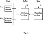
- the multi-pipe-switching heat exchange apparatus in accordance with the present invention has a heating module, an auxiliary module, a buffering module, and an operation module.
- the heating module has at least one heating boiler.
- the auxiliary module is deposited beside the heating module and has at least one spare boiler.
- the buffering module is connected to and communicates with the heating module and the auxiliary module, and has a buffering body connected to and communicating with the at least one heating boiler and the at least one spare boiler, a first pipeline set deposited between the buffering body and the heating module, and a second pipeline set deposited between the buffering body and the auxiliary module.
- the operation module is connected to and communicates with the buffering module and has an operation end and a third pipeline set connected to and communicating with the buffering body and the operation end.
- a first embodiment of a multi-pipe-switching heat exchange apparatus in accordance with the present invention has a heating module 10, an auxiliary module 20, a buffering module 30, an operation module 40, and multiple valve modules 50.
- the heating module 10 is used to produce a heat source and has at least one heating boiler 11, a preheater 12, and a chimney pipe group 13.
- the at least one heating boiler 11 is deposited uprightly and may be a steam boiler or a hot water boiler.
- the preheater 12 is deposited beside the at least one heating boiler 11, and is connected to and communicates with the at least one heating boiler 11.
- the preheater 12 may adjust the temperature of the heat source before the heat source enters the at least one heating boiler 11 via the preheater 12, and this may prevent the excessive temperature of the heat source from directly entering and damaging the at least one heating boiler 11.
- the heat source may be generated or supplied by a burner or a biomass fuel combustion furnace.
- the chimney pipe group 13 is connected to and communicates with a top of the at least one heating boiler 11, is opposite the preheater 12, and is used to guide the heat source after heat exchanging and the fuel gas flowing out of the at least one heating boiler 11, and this may avoid excessive pressure causing danger within the at least one heating boiler 11. In addition, after heat exchange of the heat source and when the fuel gas flows out to the external environment via the chimney pipe group 13, this may provide an effect of discharging hot air and importing cold air.
- the auxiliary module 20 is deposited beside the heating module 10 and has at least one spare boiler 21.
- the at least one spare boiler 21 may be a steam boiler or a hot water boiler.
- the buffering module 30 is connected to and communicates with the heating module 10 and the auxiliary module 20, and has a buffering body 31, a first pipeline set 32, a second pipeline set 33, and a fluid supply device 34.
- the buffering body 31 is connected to and communicates with the at least one heating boiler 11 and the at least one spare boiler 21, and has an exchange fluid to transport the heat sources that are generated from the at least one heating boiler 11 and the at least one spare boiler 21 in the buffering body 31.
- the first pipeline set 32 is deposited and connected between the buffering body 31 and the heating module 10 to form a closed circulation loop (first circulation loop) between the buffering body 31, the preheater 12, and the at least one heating boiler 11.
- the second pipeline set 33 is deposited and connected between the buffering body 31 and the auxiliary module 20 to form a closed circulation loop (second circulation loop) between the buffering body 31 and the at least one spare boiler 21.
- the fluid supply device 34 is connected to and communicates with the buffering body 31 to supplement the content of the exchange fluid.
- the operation module 40 is connected to and communicates with the buffering module 30 and has a third pipeline set 41 and an operation end 42.
- the third pipeline set 41 is connected to and communicates with the buffering body 31 and the operation end 42 to form a closed circulation loop (third circulation loop) between the buffering body 31 and the operation end 42 of the operation module 40.
- the pipeline sets 32, 33, 41 do not communicate with each other to form each one of the circulation loops as an independent loop.
- the operation end 42 of the operation module 40 may be a greenhouse.
- Each one of the valve modules 50 is of the dual-tube type, is deposited at a connecting end of the buffering body 31 such that each one of the pipeline sets 32, 33, 41 is connected to and communicates with the buffering body 31, and each one of the valve modules 50 has two branch pipes 51, two pumps 52, and multiple control valves 53.
- the branch pipes 51 are connected to and communicate with the buffering body 31 and one of the pipeline sets 32, 33, 41.
- the two pumps 52 are deposited on the two branch pipes 51.
- the control valves 53 are deposited on the branch pipes 51 beside the pumps 52.
- the multi-pipe-switching heat exchange apparatus needs regular maintenance or repair
- one of the two branch pipes 51 of each one of the valve modules 50 is closed by the control valves 53, and the other one of the two branch pipes 51 of the valve module 50 is open.
- the maintenance work such as regular check-up, repair, or replacement can be performed for a part of the components of the multi-pipe-switching heat exchange apparatus during the normal operation.
- the heat source is generated from the heating module 10 and is transported into the at least one heating boiler 11 after the temperature adjustment of the preheater 12, and exchanges heat with the exchange fluid in the buffering body 31 via the first pipeline set 32. Then, the heat source that is generated from the heating module 10 forms a first heat exchange cycle in the first circulation loop between the preheater 12, the at least one heating boiler 11, the first pipeline set 32, and the buffering body 31. After the exchange fluid in the buffering body 31 absorbs the heat of the heat source of the heating module 10, the heat may be transported to the operation end 42 via the third pipeline set 41, so that the user can use the heat at the operation end 42.
- the exchange fluid in the buffering body 31 may provide a buffering effect to avoid excessive amount of the heat source being directly supplied to the operation end 42 of the operation module 40, and this may prevent the temperature getting too high.
- the heat source that is transported from the buffering body 31 forms a third heat exchange cycle in the third circulation loop between the buffering body 31, the third pipeline set 41, and the operation end 42. Additionally, the heat source is transported in the first heat exchange cycle and the third heat exchange cycle via the buffering body 31, and the first and third heat exchange cycles are independent and do not interfere with each other.
- the at least one spare boiler 21 of the auxiliary module 20 is started to generate and transport an auxiliary heat source to the buffering body 31 via the second pipeline set 33. Then, the exchange fluid in the buffering body 31 may absorb more heat, and a second heat exchange cycle is formed between the at least one spare boiler 21, the second pipeline set 33, and the buffering body 31.
- the auxiliary heat source may be transported to the operation end 42 via the third pipeline set 41 to supplement the amount of heat source that is insufficient at the heating module 10. Then, the user may adjust the temperature at the operation end 42 according to the user's need and may provide adequate heat sources when requiring large usage amount of heat. Furthermore, the heat source is transported in the second heat exchange cycle and the third heat exchange cycle via the buffering body 31, and the second and third heat exchange cycles are independent and do not interfere with each other.
- the multi-pipe-switching heat exchange apparatus of the present invention may meet the need at the operation end 42 to exchange heat in a single piping mode between the heating module 10, the buffering module 30, and the operation module 40, and the auxiliary module 20 can be used according to the condition, thereby forming a dual-piping mode of heat exchange.
- the heat exchange cycles are independent of each other without interference and are connected to and communicate with the buffering body 31 of the buffering module 30, and this may provide a complementary and auxiliary effect between the heat exchange cycles.
- the heating module 10 of the multi-pipe-switching heat exchange apparatus is broken or leaking, the heat source can be conveyed through other circulation loops by switching the valve module 50 without stopping the operation of the whole multi-pipe-switching heat exchange apparatus.
- multiple heat sources can be supplied by the heating module 10 and the auxiliary module 20 in use, and this may reduce the time required for preheating and the heat sources are adjustable and switchable according to the used amount of the heat source to reduce the time and cost of use.
- the buffering module 30 is deposited between the heating module 10, the auxiliary module 20, and the operation module 40 and may provide a buffering effect to the multi-pipe-switching heat exchange apparatus when the amount of the generated heat source is larger than the amount of the required heat source, and this may prevent the temperature from getting too high.
- one of the branch pipes 51 of each one of the valve modules 50 is closed and the other one of the branch pipes 51 of the valve module 50 is open to provide a switching effect to the multi-pipe-switching heat exchange apparatus. Then, a part of the components of the multi-pipe-switching heat exchange apparatus may be inspected, repaired, or replaced during the normal operation, and this may improve the convenience of use and maintenance.
- a cooling module 60 is connected to and communicates with the buffering module 30 to adjust the temperature of the greenhouse of the operation module 40, and has two ends. One of the two ends of the cooling module 60 is connected to and communicates with the buffering body 31 of the buffering module 30 by one of the valve modules 50, and the other end of the cooling module 60 is connected to and communicates with the buffering body 31 by a fourth pipeline set 61 to form a fourth circulation loop.
- the cooling module 60 may be the ground water, ice water or other cooling sources. Then, the user at the operation end 42 of the operation module 40 may adjust the temperature of the operation end 42 conveniently and easily by the circulation loops.
- the multi-pipe-switching heat exchange apparatus in the present invention has the following advantages.
Landscapes
- Engineering & Computer Science (AREA)
- Physics & Mathematics (AREA)
- Thermal Sciences (AREA)
- Mechanical Engineering (AREA)
- General Engineering & Computer Science (AREA)
- Chemical & Material Sciences (AREA)
- Combustion & Propulsion (AREA)
- Steam Or Hot-Water Central Heating Systems (AREA)
- Heat-Exchange Devices With Radiators And Conduit Assemblies (AREA)
- Central Heating Systems (AREA)
Priority Applications (2)
| Application Number | Priority Date | Filing Date | Title |
|---|---|---|---|
| ES16195695T ES2721249T3 (es) | 2016-10-26 | 2016-10-26 | Aparato de intercambio de calos de múltiples tubos |
| EP16195695.8A EP3315867B1 (de) | 2016-10-26 | 2016-10-26 | Wärmeaustauschvorrichtung mit mehrfachrohrschaltung |
Applications Claiming Priority (1)
| Application Number | Priority Date | Filing Date | Title |
|---|---|---|---|
| EP16195695.8A EP3315867B1 (de) | 2016-10-26 | 2016-10-26 | Wärmeaustauschvorrichtung mit mehrfachrohrschaltung |
Publications (2)
| Publication Number | Publication Date |
|---|---|
| EP3315867A1 true EP3315867A1 (de) | 2018-05-02 |
| EP3315867B1 EP3315867B1 (de) | 2019-03-27 |
Family
ID=57208158
Family Applications (1)
| Application Number | Title | Priority Date | Filing Date |
|---|---|---|---|
| EP16195695.8A Active EP3315867B1 (de) | 2016-10-26 | 2016-10-26 | Wärmeaustauschvorrichtung mit mehrfachrohrschaltung |
Country Status (2)
| Country | Link |
|---|---|
| EP (1) | EP3315867B1 (de) |
| ES (1) | ES2721249T3 (de) |
Citations (5)
| Publication number | Priority date | Publication date | Assignee | Title |
|---|---|---|---|---|
| DE202007018564U1 (de) * | 2007-09-01 | 2008-12-11 | Robert Bosch Gmbh | Heizungs- und/oder Warmwasserbereitungssystem |
| GB2473684A (en) * | 2009-09-18 | 2011-03-23 | Waterford Foundry | Control unit for a heating system |
| US20140373825A1 (en) * | 2011-07-06 | 2014-12-25 | Simon Redford | Apparatus for capturing heat from a stove |
| DE202016001999U1 (de) * | 2016-03-24 | 2016-06-02 | Schwarz Elektrotechnik - Schaltanlagen - Ölfeuerung e.K. | Automatische Aufladeregelung für Öl-/Gas-Kessel mit Holzkessel und Pufferspeicher |
| EP3073200A1 (de) * | 2015-03-27 | 2016-09-28 | Robert Bosch Gmbh | Beheizte hydraulische weiche zur optimierten einbindung von fremdwärme |
-
2016
- 2016-10-26 EP EP16195695.8A patent/EP3315867B1/de active Active
- 2016-10-26 ES ES16195695T patent/ES2721249T3/es active Active
Patent Citations (5)
| Publication number | Priority date | Publication date | Assignee | Title |
|---|---|---|---|---|
| DE202007018564U1 (de) * | 2007-09-01 | 2008-12-11 | Robert Bosch Gmbh | Heizungs- und/oder Warmwasserbereitungssystem |
| GB2473684A (en) * | 2009-09-18 | 2011-03-23 | Waterford Foundry | Control unit for a heating system |
| US20140373825A1 (en) * | 2011-07-06 | 2014-12-25 | Simon Redford | Apparatus for capturing heat from a stove |
| EP3073200A1 (de) * | 2015-03-27 | 2016-09-28 | Robert Bosch Gmbh | Beheizte hydraulische weiche zur optimierten einbindung von fremdwärme |
| DE202016001999U1 (de) * | 2016-03-24 | 2016-06-02 | Schwarz Elektrotechnik - Schaltanlagen - Ölfeuerung e.K. | Automatische Aufladeregelung für Öl-/Gas-Kessel mit Holzkessel und Pufferspeicher |
Also Published As
| Publication number | Publication date |
|---|---|
| EP3315867B1 (de) | 2019-03-27 |
| ES2721249T3 (es) | 2019-07-30 |
Similar Documents
| Publication | Publication Date | Title |
|---|---|---|
| CN104832232B (zh) | 一种梯级换热有机朗肯循环发电系统及其发电方法 | |
| CN105423592B (zh) | 双工况直燃双效型溴化锂吸收式热泵机组 | |
| US20210180473A1 (en) | Combined cycle power plant with improved efficiency | |
| CN103759462B (zh) | 带烟气溶液换热器的烟气型溴化锂吸收式制冷机组 | |
| KR101965756B1 (ko) | 증기보일러의 폐열 회수장치 | |
| KR101842713B1 (ko) | 증기보일러의 폐열 회수장치 | |
| CN204187709U (zh) | 一种储热供暖系统 | |
| EP3315867B1 (de) | Wärmeaustauschvorrichtung mit mehrfachrohrschaltung | |
| CN211450986U (zh) | 一种热量传递系统 | |
| US20180119965A1 (en) | Multi-pipe-switching heat exchange apparatus | |
| CN104990062B (zh) | 一种锅炉节能方法和节能装置 | |
| CN112944321A (zh) | 吹管期间提高锅炉给水温度的系统及其使用方法 | |
| CN103759459B (zh) | 烟气热水单双效复合型溴化锂吸收式制冷机组 | |
| CN108036383B (zh) | 余热储热回收系统 | |
| KR101203966B1 (ko) | 발전소용 폐열 재활용장치 | |
| CN206221074U (zh) | 一种用于燃机单循环和联合循环的天然气加热系统 | |
| CN206362241U (zh) | 多管路切换的热交换装置 | |
| CN214581018U (zh) | 吹管期间提高锅炉给水温度的系统 | |
| CN211526399U (zh) | 一种导热油锅炉 | |
| CN211084190U (zh) | 一种工厂冷凝水回收利用系统 | |
| CN209386263U (zh) | 一种辅助加热的固体储热系统 | |
| KR101917003B1 (ko) | 다중 배관 스위칭식 열교환 기구 | |
| CN222257032U (zh) | 一种锅炉用水预热升温装置 | |
| CN205065683U (zh) | 一种启动锅炉排污水热量回收系统 | |
| CN110873335A (zh) | 一种热量传递系统及其调整控制方法 |
Legal Events
| Date | Code | Title | Description |
|---|---|---|---|
| PUAI | Public reference made under article 153(3) epc to a published international application that has entered the european phase |
Free format text: ORIGINAL CODE: 0009012 |
|
| STAA | Information on the status of an ep patent application or granted ep patent |
Free format text: STATUS: REQUEST FOR EXAMINATION WAS MADE |
|
| 17P | Request for examination filed |
Effective date: 20170726 |
|
| AK | Designated contracting states |
Kind code of ref document: A1 Designated state(s): AL AT BE BG CH CY CZ DE DK EE ES FI FR GB GR HR HU IE IS IT LI LT LU LV MC MK MT NL NO PL PT RO RS SE SI SK SM TR |
|
| AX | Request for extension of the european patent |
Extension state: BA ME |
|
| GRAP | Despatch of communication of intention to grant a patent |
Free format text: ORIGINAL CODE: EPIDOSNIGR1 |
|
| STAA | Information on the status of an ep patent application or granted ep patent |
Free format text: STATUS: GRANT OF PATENT IS INTENDED |
|
| INTG | Intention to grant announced |
Effective date: 20180717 |
|
| GRAS | Grant fee paid |
Free format text: ORIGINAL CODE: EPIDOSNIGR3 |
|
| GRAA | (expected) grant |
Free format text: ORIGINAL CODE: 0009210 |
|
| STAA | Information on the status of an ep patent application or granted ep patent |
Free format text: STATUS: THE PATENT HAS BEEN GRANTED |
|
| AK | Designated contracting states |
Kind code of ref document: B1 Designated state(s): AL AT BE BG CH CY CZ DE DK EE ES FI FR GB GR HR HU IE IS IT LI LT LU LV MC MK MT NL NO PL PT RO RS SE SI SK SM TR |
|
| REG | Reference to a national code |
Ref country code: GB Ref legal event code: FG4D |
|
| REG | Reference to a national code |
Ref country code: CH Ref legal event code: EP |
|
| REG | Reference to a national code |
Ref country code: AT Ref legal event code: REF Ref document number: 1113550 Country of ref document: AT Kind code of ref document: T Effective date: 20190415 |
|
| REG | Reference to a national code |
Ref country code: IE Ref legal event code: FG4D |
|
| REG | Reference to a national code |
Ref country code: DE Ref legal event code: R096 Ref document number: 602016011513 Country of ref document: DE |
|
| REG | Reference to a national code |
Ref country code: ES Ref legal event code: FG2A Ref document number: 2721249 Country of ref document: ES Kind code of ref document: T3 Effective date: 20190730 |
|
| PG25 | Lapsed in a contracting state [announced via postgrant information from national office to epo] |
Ref country code: SE Free format text: LAPSE BECAUSE OF FAILURE TO SUBMIT A TRANSLATION OF THE DESCRIPTION OR TO PAY THE FEE WITHIN THE PRESCRIBED TIME-LIMIT Effective date: 20190327 Ref country code: LT Free format text: LAPSE BECAUSE OF FAILURE TO SUBMIT A TRANSLATION OF THE DESCRIPTION OR TO PAY THE FEE WITHIN THE PRESCRIBED TIME-LIMIT Effective date: 20190327 Ref country code: NO Free format text: LAPSE BECAUSE OF FAILURE TO SUBMIT A TRANSLATION OF THE DESCRIPTION OR TO PAY THE FEE WITHIN THE PRESCRIBED TIME-LIMIT Effective date: 20190627 Ref country code: FI Free format text: LAPSE BECAUSE OF FAILURE TO SUBMIT A TRANSLATION OF THE DESCRIPTION OR TO PAY THE FEE WITHIN THE PRESCRIBED TIME-LIMIT Effective date: 20190327 |
|
| REG | Reference to a national code |
Ref country code: NL Ref legal event code: MP Effective date: 20190327 |
|
| PG25 | Lapsed in a contracting state [announced via postgrant information from national office to epo] |
Ref country code: RS Free format text: LAPSE BECAUSE OF FAILURE TO SUBMIT A TRANSLATION OF THE DESCRIPTION OR TO PAY THE FEE WITHIN THE PRESCRIBED TIME-LIMIT Effective date: 20190327 Ref country code: NL Free format text: LAPSE BECAUSE OF FAILURE TO SUBMIT A TRANSLATION OF THE DESCRIPTION OR TO PAY THE FEE WITHIN THE PRESCRIBED TIME-LIMIT Effective date: 20190327 Ref country code: HR Free format text: LAPSE BECAUSE OF FAILURE TO SUBMIT A TRANSLATION OF THE DESCRIPTION OR TO PAY THE FEE WITHIN THE PRESCRIBED TIME-LIMIT Effective date: 20190327 Ref country code: GR Free format text: LAPSE BECAUSE OF FAILURE TO SUBMIT A TRANSLATION OF THE DESCRIPTION OR TO PAY THE FEE WITHIN THE PRESCRIBED TIME-LIMIT Effective date: 20190628 Ref country code: LV Free format text: LAPSE BECAUSE OF FAILURE TO SUBMIT A TRANSLATION OF THE DESCRIPTION OR TO PAY THE FEE WITHIN THE PRESCRIBED TIME-LIMIT Effective date: 20190327 |
|
| REG | Reference to a national code |
Ref country code: AT Ref legal event code: MK05 Ref document number: 1113550 Country of ref document: AT Kind code of ref document: T Effective date: 20190327 |
|
| PG25 | Lapsed in a contracting state [announced via postgrant information from national office to epo] |
Ref country code: AL Free format text: LAPSE BECAUSE OF FAILURE TO SUBMIT A TRANSLATION OF THE DESCRIPTION OR TO PAY THE FEE WITHIN THE PRESCRIBED TIME-LIMIT Effective date: 20190327 Ref country code: PT Free format text: LAPSE BECAUSE OF FAILURE TO SUBMIT A TRANSLATION OF THE DESCRIPTION OR TO PAY THE FEE WITHIN THE PRESCRIBED TIME-LIMIT Effective date: 20190727 Ref country code: SK Free format text: LAPSE BECAUSE OF FAILURE TO SUBMIT A TRANSLATION OF THE DESCRIPTION OR TO PAY THE FEE WITHIN THE PRESCRIBED TIME-LIMIT Effective date: 20190327 Ref country code: EE Free format text: LAPSE BECAUSE OF FAILURE TO SUBMIT A TRANSLATION OF THE DESCRIPTION OR TO PAY THE FEE WITHIN THE PRESCRIBED TIME-LIMIT Effective date: 20190327 Ref country code: RO Free format text: LAPSE BECAUSE OF FAILURE TO SUBMIT A TRANSLATION OF THE DESCRIPTION OR TO PAY THE FEE WITHIN THE PRESCRIBED TIME-LIMIT Effective date: 20190327 Ref country code: CZ Free format text: LAPSE BECAUSE OF FAILURE TO SUBMIT A TRANSLATION OF THE DESCRIPTION OR TO PAY THE FEE WITHIN THE PRESCRIBED TIME-LIMIT Effective date: 20190327 |
|
| PG25 | Lapsed in a contracting state [announced via postgrant information from national office to epo] |
Ref country code: PL Free format text: LAPSE BECAUSE OF FAILURE TO SUBMIT A TRANSLATION OF THE DESCRIPTION OR TO PAY THE FEE WITHIN THE PRESCRIBED TIME-LIMIT Effective date: 20190327 Ref country code: SM Free format text: LAPSE BECAUSE OF FAILURE TO SUBMIT A TRANSLATION OF THE DESCRIPTION OR TO PAY THE FEE WITHIN THE PRESCRIBED TIME-LIMIT Effective date: 20190327 |
|
| PG25 | Lapsed in a contracting state [announced via postgrant information from national office to epo] |
Ref country code: IS Free format text: LAPSE BECAUSE OF FAILURE TO SUBMIT A TRANSLATION OF THE DESCRIPTION OR TO PAY THE FEE WITHIN THE PRESCRIBED TIME-LIMIT Effective date: 20190727 Ref country code: AT Free format text: LAPSE BECAUSE OF FAILURE TO SUBMIT A TRANSLATION OF THE DESCRIPTION OR TO PAY THE FEE WITHIN THE PRESCRIBED TIME-LIMIT Effective date: 20190327 |
|
| REG | Reference to a national code |
Ref country code: DE Ref legal event code: R097 Ref document number: 602016011513 Country of ref document: DE |
|
| PG25 | Lapsed in a contracting state [announced via postgrant information from national office to epo] |
Ref country code: DK Free format text: LAPSE BECAUSE OF FAILURE TO SUBMIT A TRANSLATION OF THE DESCRIPTION OR TO PAY THE FEE WITHIN THE PRESCRIBED TIME-LIMIT Effective date: 20190327 |
|
| PLBE | No opposition filed within time limit |
Free format text: ORIGINAL CODE: 0009261 |
|
| STAA | Information on the status of an ep patent application or granted ep patent |
Free format text: STATUS: NO OPPOSITION FILED WITHIN TIME LIMIT |
|
| 26N | No opposition filed |
Effective date: 20200103 |
|
| REG | Reference to a national code |
Ref country code: DE Ref legal event code: R119 Ref document number: 602016011513 Country of ref document: DE |
|
| PG25 | Lapsed in a contracting state [announced via postgrant information from national office to epo] |
Ref country code: MC Free format text: LAPSE BECAUSE OF FAILURE TO SUBMIT A TRANSLATION OF THE DESCRIPTION OR TO PAY THE FEE WITHIN THE PRESCRIBED TIME-LIMIT Effective date: 20190327 |
|
| REG | Reference to a national code |
Ref country code: CH Ref legal event code: PL |
|
| PG25 | Lapsed in a contracting state [announced via postgrant information from national office to epo] |
Ref country code: LU Free format text: LAPSE BECAUSE OF NON-PAYMENT OF DUE FEES Effective date: 20191026 Ref country code: DE Free format text: LAPSE BECAUSE OF NON-PAYMENT OF DUE FEES Effective date: 20200501 Ref country code: LI Free format text: LAPSE BECAUSE OF NON-PAYMENT OF DUE FEES Effective date: 20191031 Ref country code: CH Free format text: LAPSE BECAUSE OF NON-PAYMENT OF DUE FEES Effective date: 20191031 |
|
| REG | Reference to a national code |
Ref country code: BE Ref legal event code: MM Effective date: 20191031 |
|
| PG25 | Lapsed in a contracting state [announced via postgrant information from national office to epo] |
Ref country code: BE Free format text: LAPSE BECAUSE OF NON-PAYMENT OF DUE FEES Effective date: 20191031 |
|
| PG25 | Lapsed in a contracting state [announced via postgrant information from national office to epo] |
Ref country code: IE Free format text: LAPSE BECAUSE OF NON-PAYMENT OF DUE FEES Effective date: 20191026 Ref country code: FR Free format text: LAPSE BECAUSE OF NON-PAYMENT OF DUE FEES Effective date: 20191031 |
|
| PG25 | Lapsed in a contracting state [announced via postgrant information from national office to epo] |
Ref country code: CY Free format text: LAPSE BECAUSE OF FAILURE TO SUBMIT A TRANSLATION OF THE DESCRIPTION OR TO PAY THE FEE WITHIN THE PRESCRIBED TIME-LIMIT Effective date: 20190327 |
|
| GBPC | Gb: european patent ceased through non-payment of renewal fee |
Effective date: 20201026 |
|
| PG25 | Lapsed in a contracting state [announced via postgrant information from national office to epo] |
Ref country code: MT Free format text: LAPSE BECAUSE OF FAILURE TO SUBMIT A TRANSLATION OF THE DESCRIPTION OR TO PAY THE FEE WITHIN THE PRESCRIBED TIME-LIMIT Effective date: 20190327 Ref country code: HU Free format text: LAPSE BECAUSE OF FAILURE TO SUBMIT A TRANSLATION OF THE DESCRIPTION OR TO PAY THE FEE WITHIN THE PRESCRIBED TIME-LIMIT; INVALID AB INITIO Effective date: 20161026 |
|
| PG25 | Lapsed in a contracting state [announced via postgrant information from national office to epo] |
Ref country code: GB Free format text: LAPSE BECAUSE OF NON-PAYMENT OF DUE FEES Effective date: 20201026 |
|
| PG25 | Lapsed in a contracting state [announced via postgrant information from national office to epo] |
Ref country code: SI Free format text: LAPSE BECAUSE OF FAILURE TO SUBMIT A TRANSLATION OF THE DESCRIPTION OR TO PAY THE FEE WITHIN THE PRESCRIBED TIME-LIMIT Effective date: 20190327 |
|
| PG25 | Lapsed in a contracting state [announced via postgrant information from national office to epo] |
Ref country code: MK Free format text: LAPSE BECAUSE OF FAILURE TO SUBMIT A TRANSLATION OF THE DESCRIPTION OR TO PAY THE FEE WITHIN THE PRESCRIBED TIME-LIMIT Effective date: 20190327 |
|
| PGFP | Annual fee paid to national office [announced via postgrant information from national office to epo] |
Ref country code: IT Payment date: 20251021 Year of fee payment: 10 |
|
| PGFP | Annual fee paid to national office [announced via postgrant information from national office to epo] |
Ref country code: TR Payment date: 20251007 Year of fee payment: 10 |
|
| PGFP | Annual fee paid to national office [announced via postgrant information from national office to epo] |
Ref country code: BG Payment date: 20251028 Year of fee payment: 10 |
|
| PGFP | Annual fee paid to national office [announced via postgrant information from national office to epo] |
Ref country code: ES Payment date: 20251118 Year of fee payment: 10 |