EP3316459A1 - Moteurs électriques - Google Patents
Moteurs électriques Download PDFInfo
- Publication number
- EP3316459A1 EP3316459A1 EP17197855.4A EP17197855A EP3316459A1 EP 3316459 A1 EP3316459 A1 EP 3316459A1 EP 17197855 A EP17197855 A EP 17197855A EP 3316459 A1 EP3316459 A1 EP 3316459A1
- Authority
- EP
- European Patent Office
- Prior art keywords
- electric motor
- rotor
- magnetic field
- magnetic flux
- winding
- Prior art date
- Legal status (The legal status is an assumption and is not a legal conclusion. Google has not performed a legal analysis and makes no representation as to the accuracy of the status listed.)
- Granted
Links
Images


Classifications
-
- H—ELECTRICITY
- H02—GENERATION; CONVERSION OR DISTRIBUTION OF ELECTRIC POWER
- H02K—DYNAMO-ELECTRIC MACHINES
- H02K1/00—Details of the magnetic circuit
- H02K1/06—Details of the magnetic circuit characterised by the shape, form or construction
- H02K1/22—Rotating parts of the magnetic circuit
- H02K1/223—Rotor cores with windings and permanent magnets
-
- H—ELECTRICITY
- H02—GENERATION; CONVERSION OR DISTRIBUTION OF ELECTRIC POWER
- H02K—DYNAMO-ELECTRIC MACHINES
- H02K1/00—Details of the magnetic circuit
- H02K1/06—Details of the magnetic circuit characterised by the shape, form or construction
- H02K1/12—Stationary parts of the magnetic circuit
- H02K1/14—Stator cores with salient poles
- H02K1/146—Stator cores with salient poles consisting of a generally annular yoke with salient poles
-
- H—ELECTRICITY
- H02—GENERATION; CONVERSION OR DISTRIBUTION OF ELECTRIC POWER
- H02K—DYNAMO-ELECTRIC MACHINES
- H02K1/00—Details of the magnetic circuit
- H02K1/06—Details of the magnetic circuit characterised by the shape, form or construction
- H02K1/22—Rotating parts of the magnetic circuit
- H02K1/27—Rotor cores with permanent magnets
- H02K1/2706—Inner rotors
- H02K1/272—Inner rotors the magnetisation axis of the magnets being perpendicular to the rotor axis
- H02K1/274—Inner rotors the magnetisation axis of the magnets being perpendicular to the rotor axis the rotor consisting of two or more circumferentially positioned magnets
- H02K1/2753—Inner rotors the magnetisation axis of the magnets being perpendicular to the rotor axis the rotor consisting of two or more circumferentially positioned magnets the rotor consisting of magnets or groups of magnets arranged with alternating polarity
- H02K1/276—Magnets embedded in the magnetic core, e.g. interior permanent magnets [IPM]
-
- H—ELECTRICITY
- H02—GENERATION; CONVERSION OR DISTRIBUTION OF ELECTRIC POWER
- H02K—DYNAMO-ELECTRIC MACHINES
- H02K21/00—Synchronous motors having permanent magnets; Synchronous generators having permanent magnets
- H02K21/02—Details
- H02K21/04—Windings on magnets for additional excitation ; Windings and magnets for additional excitation
- H02K21/046—Windings on magnets for additional excitation ; Windings and magnets for additional excitation with rotating permanent magnets and stationary field winding
-
- H—ELECTRICITY
- H02—GENERATION; CONVERSION OR DISTRIBUTION OF ELECTRIC POWER
- H02K—DYNAMO-ELECTRIC MACHINES
- H02K21/00—Synchronous motors having permanent magnets; Synchronous generators having permanent magnets
- H02K21/12—Synchronous motors having permanent magnets; Synchronous generators having permanent magnets with stationary armatures and rotating magnets
- H02K21/14—Synchronous motors having permanent magnets; Synchronous generators having permanent magnets with stationary armatures and rotating magnets with magnets rotating within the armatures
-
- H—ELECTRICITY
- H02—GENERATION; CONVERSION OR DISTRIBUTION OF ELECTRIC POWER
- H02K—DYNAMO-ELECTRIC MACHINES
- H02K3/00—Details of windings
- H02K3/04—Windings characterised by the conductor shape, form or construction, e.g. with bar conductors
- H02K3/18—Windings for salient poles
-
- H—ELECTRICITY
- H02—GENERATION; CONVERSION OR DISTRIBUTION OF ELECTRIC POWER
- H02P—CONTROL OR REGULATION OF ELECTRIC MOTORS, ELECTRIC GENERATORS OR DYNAMO-ELECTRIC CONVERTERS; CONTROLLING TRANSFORMERS, REACTORS OR CHOKE COILS
- H02P1/00—Arrangements for starting electric motors or dynamo-electric converters
- H02P1/16—Arrangements for starting electric motors or dynamo-electric converters for starting dynamo-electric motors or dynamo-electric converters
- H02P1/46—Arrangements for starting electric motors or dynamo-electric converters for starting dynamo-electric motors or dynamo-electric converters for starting an individual synchronous motor
-
- H—ELECTRICITY
- H02—GENERATION; CONVERSION OR DISTRIBUTION OF ELECTRIC POWER
- H02P—CONTROL OR REGULATION OF ELECTRIC MOTORS, ELECTRIC GENERATORS OR DYNAMO-ELECTRIC CONVERTERS; CONTROLLING TRANSFORMERS, REACTORS OR CHOKE COILS
- H02P6/00—Arrangements for controlling synchronous motors or other dynamo-electric motors using electronic commutation dependent on the rotor position; Electronic commutators therefor
- H02P6/08—Arrangements for controlling the speed or torque of a single motor
-
- H—ELECTRICITY
- H02—GENERATION; CONVERSION OR DISTRIBUTION OF ELECTRIC POWER
- H02K—DYNAMO-ELECTRIC MACHINES
- H02K21/00—Synchronous motors having permanent magnets; Synchronous generators having permanent magnets
- H02K21/46—Motors having additional short-circuited winding for starting as an asynchronous motor
-
- H—ELECTRICITY
- H02—GENERATION; CONVERSION OR DISTRIBUTION OF ELECTRIC POWER
- H02K—DYNAMO-ELECTRIC MACHINES
- H02K2213/00—Specific aspects, not otherwise provided for and not covered by codes H02K2201/00 - H02K2211/00
- H02K2213/03—Machines characterised by numerical values, ranges, mathematical expressions or similar information
-
- H—ELECTRICITY
- H02—GENERATION; CONVERSION OR DISTRIBUTION OF ELECTRIC POWER
- H02K—DYNAMO-ELECTRIC MACHINES
- H02K3/00—Details of windings
- H02K3/04—Windings characterised by the conductor shape, form or construction, e.g. with bar conductors
- H02K3/18—Windings for salient poles
- H02K3/20—Windings for salient poles for auxiliary purposes, e.g. damping or commutating
-
- H—ELECTRICITY
- H02—GENERATION; CONVERSION OR DISTRIBUTION OF ELECTRIC POWER
- H02K—DYNAMO-ELECTRIC MACHINES
- H02K3/00—Details of windings
- H02K3/46—Fastening of windings on the stator or rotor structure
- H02K3/48—Fastening of windings on the stator or rotor structure in slots
- H02K3/487—Slot-closing devices
- H02K3/493—Slot-closing devices magnetic
Definitions
- the present disclosure relates to electric motors, and more particularly to electric motors and electric motor arrangements for hybrid-electric aircraft.
- Aircraft commonly employ gas turbine engine-based propulsion architectures, which rely on thrust generated by a gas turbine for propulsion.
- hybrid-electric propulsion architectures have received consideration due their potential for reduced emissions and acoustic noise in comparison to gas turbine engine-based propulsion architectures.
- Hybrid-electric architectures allow for employment the gas turbine engine(s) within a relatively narrow operating, exploiting the flexibility of electric motors to improve engine efficiency.
- Starting and speed control can be using dedicated drives for electric motors employing solid-state inverter.
- Solid-state inverters enable provision of motor-specific variable voltage variable frequency power sources which cooperate with rotor position sensors, or employ sensorless zero/low speed control regimes to provide starting and speed control.
- An electric motor includes a rotor having plurality of permanent magnets and defining a rotation axis, a cage winding fixed to rotor radially outward of the permanent magnets, a stator, and a plurality of magnetic flux diverters.
- the stator extends about the rotor and has a power winding.
- the magnetic flux diverters are distributed about the stator radially between the power winding and an air gap between the rotor and the stator, and are configured to shunt magnetic flux within the stator for starting rotor rotation and controlling rotational speed of the rotor.
- a variable voltage variable frequency alternating current (AC) power source can be connected to the stator power winding.
- a direct current (DC) power source can be connected to the magnetic flux diverter control winding.
- a voltage controller can be connected to the magnetic flux diverters. The voltage controller can have a starting mode, an asynchronous speed mode, and a synchronous speed mode which modulate magnetic communication between the stator and rotor. Current flow to the magnetic flux diverter control windings can be greater in the starting mode than in the synchronous mode. Current flow to the magnetic flux diverter control windings can be greater in the asynchronous rotational speed mode than in the starting mode.
- the power winding can be a three phase AC power winding.
- the cage winding can include two or more conductor rods.
- the conductor rods can extend axially along the rotor and connect to end rings.
- the conductor rods can be seated within poles shoes of the rotor.
- the conductor rods can be disposed radially outward of the permanent magnets. Circumferentially adjacent pairs of conductor rods can be spaced apart from one another by a first spacing and a second spacing. The second spacing can be greater than the first spacing.
- the conductor rods can be connected in parallel with one another.
- the stator can include a yoke and stator teeth.
- the yoke can extend circumferentially about the rotor.
- the stator teeth can extend radially inward from the yoke.
- the power winding can be seated between circumferentially adjacent stator teeth.
- the power winding can be radially adjacent to the yoke.
- the magnetic flux diverters can be seated radially inward of the power winding.
- the magnetic flux diverters can seated between circumferentially adjacent stator teeth.
- the magnetic flux diverters can be radially inward of the power winding.
- the magnetic flux diverters can include a magnetic shunt.
- the magnetic flux diverters can include a control winding.
- the control winding can be wrapped about the about the magnetic shunt.
- the control winding can include a conductor with a round or rectangular cross-sectional area.
- the control winding can include ribbon conductor.
- the magnetic flux diverters can be connected electrically in series with one another by a control coil.
- An electric motor arrangement includes an electric motor as described above, a DC power source, and a variable voltage variable frequency AC power source.
- the DC power source is connected to the control windings of the magnetic flux diverters.
- the AC power source is connected to the power winding.
- a voltage controller operably with a starting mode, an asynchronous rotation mode, and a synchronous rotation mode is operably connected to the DC power source to control current flow to the control winding.
- a method of starting an electric motor includes generating a persistent magnetic field about a rotor and generating a rotating magnetic field about the persistent magnetic field.
- a current flow is induced within the rotor using the rotating magnetic field. The current flow induces a magnetic field in the rotor, thereby exerting a magnetomotive force on the rotor.
- a method of controlling rotational speed of an electric motor includes generating a persistent magnetic field about a rotor.
- a rotating magnetic field of fixed rotational speed is generated about the persistent magnetic field, the persistent magnetic field coupled with the rotating magnetic field, and magnetic flux received through the coupling shunted relative to the rotating magnetic field.
- FIG. 1 a partial view of an exemplary embodiment of an electrical motor arrangement in accordance with the disclosure is shown in Fig. 1 and is designated generally by reference character 100.
- Other embodiments of electric motor arrangements, electric motors, and related methods of starting and controlling motor speed in accordance with the disclosure, or aspects thereof, are provided in Figs. 2-5 , as will be described.
- the systems and methods described herein can be used in propulsion systems, such as in hybrid-electric aircraft, though the present disclosure is not limited to aircraft or propulsion systems in general.
- Electric motor arrangement 100 is shown. Electric motor arrangement 100 is carried by an aircraft 10 and includes a plurality of electric motors 102, a variable frequency alternating current (AC) power source 108, a fixed frequency direct current (DC) power source 110, and voltage controllers (or regulators) 112. Each electric motors 102 is operably connected to a respective propulsor 14, receives variable voltage variable frequency AC power from a single AC power bus 16, and is speed-controlled and self-started by motor-specific DC voltage controller 112 to work in concert with a gas turbine engine 12 in a hybrid-electric aircraft propulsion architecture.
- electric motors 102 are permanent magnet synchronous electric machines that are sensorless, i.e. machines which do not require a rotary position sensor for determining rotor position for purposes of starting and slow-speed operation.
- Electric motor 102 generally includes a stator 104 and a rotor 106.
- Rotor 106 defines a rotation axis 114 and is supported for rotation relative to a stator 104 about rotation axis 114.
- Stator 104 extends circumferentially about rotor 106 and may be fixed relative to a vehicle, such as aircraft 10 (shown in Fig. 1 ).
- electric motor 100 is described herein with a radially inner rotor and radially outer stator, it is to be understood and appreciated that electric motors having radially outer rotors can also benefit from the present disclosure.
- Stator 104 has a yoke 144, a plurality of stator teeth 146, a power winding 152, and a plurality of magnetic flux diverters 154.
- Yoke 144 circumferentially surrounds rotor 106.
- Stator teeth 146 extend radially inward from yoke 144 toward rotor 106.
- a gap 148 is defined between radial inner ends of stator teeth 146 and rotor 106.
- Circumferentially adjacent pairs of stator teeth 146 define between one another a plurality of stator slots 150, which are circumferentially distributed about rotor 106.
- Yoke 144 and stator teeth 146 are formed from a ferromagnetic material, such as iron or steel.
- a power winding 152 is seated within stator slots 150. Power winding 152 is electrically connected to AC power source 108 (shown in Fig. 1 ) and is arranged for generating a rotating magnetic field 134 within stator 104. It is contemplated that the rotational speed of rotating magnetic field 134 varies according to the frequency of AC power applied to power winding 152. Power winding 152 can be a polyphase AC winding to provide an electric motor with high power density. For example, power winding 152 can be a three phase AC power winding, thereby being capable of handling three times the power of a single phase AC power winding while being only 50% larger in size than a single phase AC power winding.
- Magnetic flux diverters 154 are circumferentially distributed about stator 104 within respective stator slots 150 and radially inward of power winding 152.
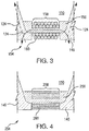
- Each magnetic flux diverter 154 includes a magnetic shunt 156 (shown in Fig. 3 ) with a control winding 158 wrapped thereabout.
- Magnetic shunt 156 is configured and adapted to operate as a magnetic wedge, throttling magnetic coupling between rotor 104 and sate 106 by shunting magnetic flux within the rotor gap current flow through control winding 158.
- the control windings 158 of each magnetic flux diverter 154 are electrically connected in series with one another to form a control coil 164.
- Control coil 164 is electrically connected to DC power source 110, which provides a flow of current to control coil 164, and therethrough to control windings 158 of magnetic flux diverter 154.
- the magnitude of the control current is controllable via voltage regulator 112.
- Rotor 106 is separated from stator 104 by gap 148 and includes a pole shoes 118, a cage winding 126, a plurality of permanent magnets 120, and a core 116.
- Core 116 extends circumferentially about rotation axis 114.
- Each of the plurality of permanent magnets 120 are arranged radially outward of core 116, are fixed relative to core 116, and are arranged to generate a persistent magnetic field 124.
- Each pole shoe 118 is arranged radially outward of a respective permanent magnet 120 radially inward of gap 148 and is fixed relative to permanent magnet 120.
- Pole shoe 118 is formed from a ferromagnetic material, such as iron of steel, which facilitates projection of persistent magnetic field 124 radially outward of pole shoe 118.
- rotor 106 has four (4) pole shoes 118 distributed circumferentially about rotation axis 114.
- electric motor 102 can have less four poles shoes or more than four poles shoes, as suitable for an intended application.
- Cage winding 126 includes a plurality of conductor rods 128 distributed circumferentially about rotor 106.
- Conductor rods 128 are seated within pole shoes 118 radially between permanent magnets 120 and gap 148.
- Each conductor rod 128 extends axially along rotor 104, is formed from an electrical conductor like copper or copper alloy, and is electrically connected in parallel with one another. It is contemplated that conductor rods 128 can be connected at axially opposite ends conductor rods 128, for example, by a conductive ring or plurality of intervening ring segments extending about rotation axis 110.
- Circumferentially adjacent pairs of conductor rods 128 are separated by a circumferential first spacing 138 or a second spacing 140.
- circumferentially adjacent pairs of conductor rods 128 seated in a common pole shoe 118 are separated by first spacing 138 and circumferentially adjacent pairs of conductor rods 128 seated in separate pole shoes 118 are separated by second spacing 140.
- Second spacing 140 is greater than first spacing 138.
- Magnetic flux diverter 154 includes a magnetic shunt 156.
- Magnetic shunt 156 is formed from a material with high permeability, such as ferromagnetic alloys or a sintered magnetic powder, and ordinarily has high magnetic reluctance.
- Control winding 158 is wrapped about magnetic shunt 156 and is electrically connected to voltage controller 112 (shown in Fig. 2 ) through control coil 164 to receive a flow of constant frequency current from DC power source 110.
- control winding 158 has a round cross-sectional area 160, which facilitates packaging magnetic flux diverter within stator slot 150 in a relatively radially compact arrangement.
- control winding 158 is used to generate a flux regulator magnetic field that is localized within stator slot 150 and fixed relative to stator 104.
- the flux regulator magnetic field cooperates with the material forming magnetic shunt 156 to throttle interaction of persistent magnetic field 124 with rotating magnetic field 134.
- Changing the extent which the persistent magnetic field 124 interacts with rotating magnetic field 134 allows for control of rotational speed of rotor 104.
- by varying a control current applied to control winding 158 the magnetic flux within yoke 144 can be controlled.
- magnetic shunt 156 when no current is supplied to control winding 158, magnetic shunt 156 reverts to a magnetically unsaturated condition. Being magnetically unsaturated, the magnetic reluctance of magnetic flux diverter 154 becomes low. Low magnetic reluctance causes substantially all magnetic flux from rotor 104 to go through magnetic shunt 156, omitting power winding 152, indicated in Fig. 3 with a solid arrow, and allowing rotational speed of rotor 104 to assume a maximum value.
- Conductor bars 128 of cage winding 126 provide starting torque for electric motor 102.
- permanent magnet synchronous machines typically are not self-starting motors.
- cage winding 126 provides torque to start rotation of rotor 104.
- 128 are formed from an electrically conductive material.
- Rotating magnetic field (of the stator power winding) 134 induces a flow of electric current through conductor bars 128.
- the current flow generates a cage winding magnetic field which interacts with rotating magnetic field 134 to exert a start-up torque on rotor 106.
- the torque e.g. starting torque T (shown in Fig.
- stator magnetic field 134 have a magnitude when rotor 106 is stationary relative to stator 104 sufficient for rotor 16 to being rotating relative to stator 104.
- Magnetic flux diverter 254 is similar to magnetic flux diverter 154 and additionally includes a ribbon conductor 258. Ribbon conductor 258 is wrapped about a magnetic shunt 256 and has a square or rectangular cross-sectional area 260. Square or rectangular cross-sectional area 260 allows magnetic shunt 256 to be stamped together with stator teeth 146, simplifying fabrication of electric motors incorporating magnetic flux diverter 254 (in Fig. 2 ).
- Electric motor 302 is similar to electric motor 102 (shown in Fig. 1 ), and additionally includes a rotor 304 with a plurality of permanent magnets 320.
- Each of the plurality of permanent magnets 320 are circumferentially offset from conductor rods 328 and the rotor pole shoes 318. The circumferential offset of each permanent magnet 320 biases a start-up torque T generated by cage winding 326.
- Biasing start-up torque T by the circumferentially offset of permanent magnets 320 provides a torque profile that decreases with a non-linear function with rotational speed, improving motor efficiency by reducing the effect that the magnetic field in cage winding 126 has on the interaction of the rotating magnetic field with the persistent magnetic fields generated by permanent magnets 320 once rotor 304 has begun rotating.
- Electric motors in conventional hybrid-electric architectures are typically supplied power from a solid state inverter power converter.
- the solid state inverter power converter allows for control of rotational speed of the electric motor by varying the frequency of variable voltage variable frequency AC power supplied to the respective electric motors by a power source. While generally satisfactory for their intended purpose, solid state inverter power controllers can add weight, cost, and/or complexity to the architecture employing such devices.
- electric motors and electric motor arrangements are provided that do not require solid state invertor arrangements.
- the electrical machines with a permanent magnet synchronous machine with magnetic flux diverters and a cage winding.
- the cage winding provides self-starting capability and stable operation at fluctuating load, and the magnetic flux diverter provides rotational speed control.
- the stator includes a power winding and control winding operatively connected to magnetic shunts seated between circumferentially adjacent stator teeth. Electric motors and electric motor arrangements described herein can eliminate the need for individual electric motor drives and/or position sensors to control position and rotational speed of the electric motor.
- Electric motors and electric motor arrangements described herein can provide relatively simply back-electromotive frequency-based sensorless control of synchronous electric motors. Electric motors and electric motor arrangements as described herein can also be relatively simple, lightweight, efficient, and/or provide reliability to hybrid-electric aircraft propulsion architectures.
Landscapes
- Engineering & Computer Science (AREA)
- Power Engineering (AREA)
- Permanent Magnet Type Synchronous Machine (AREA)
- Control Of Ac Motors In General (AREA)
- Control Of Multiple Motors (AREA)
Applications Claiming Priority (1)
| Application Number | Priority Date | Filing Date | Title |
|---|---|---|---|
| US15/335,076 US10505411B2 (en) | 2016-10-26 | 2016-10-26 | Electric motors |
Publications (2)
| Publication Number | Publication Date |
|---|---|
| EP3316459A1 true EP3316459A1 (fr) | 2018-05-02 |
| EP3316459B1 EP3316459B1 (fr) | 2021-10-13 |
Family
ID=60162073
Family Applications (1)
| Application Number | Title | Priority Date | Filing Date |
|---|---|---|---|
| EP17197855.4A Active EP3316459B1 (fr) | 2016-10-26 | 2017-10-23 | Moteurs électriques |
Country Status (2)
| Country | Link |
|---|---|
| US (1) | US10505411B2 (fr) |
| EP (1) | EP3316459B1 (fr) |
Cited By (1)
| Publication number | Priority date | Publication date | Assignee | Title |
|---|---|---|---|---|
| EP3716445A1 (fr) * | 2019-03-25 | 2020-09-30 | Hamilton Sundstrand Corporation | Générateurs et procédés de fabrication de générateurs |
Families Citing this family (6)
| Publication number | Priority date | Publication date | Assignee | Title |
|---|---|---|---|---|
| US20190068044A1 (en) * | 2010-01-25 | 2019-02-28 | Svetozar B. Petrovich | In Evolution of Gravity Fields |
| US11959174B2 (en) * | 2020-02-28 | 2024-04-16 | Applied Materials, Inc. | Shunt door for magnets in plasma process chamber |
| DE102021201603A1 (de) * | 2021-02-19 | 2022-08-25 | Zf Friedrichshafen Ag | Rotor für eine elektrische Maschine sowie elektrische Maschine mit einem Rotor |
| KR20220141085A (ko) * | 2021-04-12 | 2022-10-19 | 현대자동차주식회사 | 가변 자속 모터 제어 장치 |
| CN113765325A (zh) * | 2021-09-09 | 2021-12-07 | 上海电机系统节能工程技术研究中心有限公司 | 异步起动永磁同步电机及设备 |
| JP2024164729A (ja) * | 2023-05-15 | 2024-11-27 | マツダ株式会社 | モータ及び車両用駆動システム |
Citations (7)
| Publication number | Priority date | Publication date | Assignee | Title |
|---|---|---|---|---|
| US3614496A (en) * | 1969-01-17 | 1971-10-19 | Dordt Electromotoren | Synchronous electric motor |
| EP0680131A2 (fr) * | 1994-04-28 | 1995-11-02 | Kabushiki Kaisha Toshiba | Machine rotative du type à aimants permanents |
| JP2003111370A (ja) * | 2001-09-28 | 2003-04-11 | Fujitsu General Ltd | 電動機 |
| US20080238235A1 (en) * | 2007-03-28 | 2008-10-02 | Akeshi Takahashi | Motor and compressor using the same |
| EP2107664A2 (fr) * | 2008-04-02 | 2009-10-07 | Hamilton Sundstrand Corporation | Générateur électrique d'aimant permanent doté d'une excitation variable du flux magnétique |
| EP2157681A2 (fr) * | 2008-08-20 | 2010-02-24 | Hamilton Sundstrand Corporation | Moteur sans balai à aimant permanent régulé en flux direct utilisant un contrôle sans capteur par excitation CC et AC |
| EP2814146A2 (fr) * | 2013-06-12 | 2014-12-17 | Hamilton Sundstrand Corporation | Machines synchrones à aimant permanent avec régulation de flux magnétique |
Family Cites Families (6)
| Publication number | Priority date | Publication date | Assignee | Title |
|---|---|---|---|---|
| US2486435A (en) * | 1946-06-21 | 1949-11-01 | Harold B Rex | Alternating current motor control |
| GB677942A (en) * | 1949-06-01 | 1952-08-27 | British Thomson Houston Co Ltd | Improvements in and relating to dynamoelectric machines |
| DE1173178B (de) | 1962-07-28 | 1964-07-02 | Siemens Ag | Permanenterregte elektrische Maschine mit einem Dauermagnetbloecke enthaltenden Laeufer |
| WO2006113877A2 (fr) | 2005-04-20 | 2006-10-26 | Lugg Richard H | Aeronef vtol hybride a reaction/electrique |
| US7777384B2 (en) | 2008-04-02 | 2010-08-17 | Hamilton Sundstrand Corporation | Permanent magnet dynamoelectric machine with variable magnetic flux excitation |
| US7843155B2 (en) | 2008-04-10 | 2010-11-30 | Hamilton Sundstrand Corporation | Direct flux regulated permanent magnet brushless motor utilizing sensorless control |
-
2016
- 2016-10-26 US US15/335,076 patent/US10505411B2/en active Active
-
2017
- 2017-10-23 EP EP17197855.4A patent/EP3316459B1/fr active Active
Patent Citations (7)
| Publication number | Priority date | Publication date | Assignee | Title |
|---|---|---|---|---|
| US3614496A (en) * | 1969-01-17 | 1971-10-19 | Dordt Electromotoren | Synchronous electric motor |
| EP0680131A2 (fr) * | 1994-04-28 | 1995-11-02 | Kabushiki Kaisha Toshiba | Machine rotative du type à aimants permanents |
| JP2003111370A (ja) * | 2001-09-28 | 2003-04-11 | Fujitsu General Ltd | 電動機 |
| US20080238235A1 (en) * | 2007-03-28 | 2008-10-02 | Akeshi Takahashi | Motor and compressor using the same |
| EP2107664A2 (fr) * | 2008-04-02 | 2009-10-07 | Hamilton Sundstrand Corporation | Générateur électrique d'aimant permanent doté d'une excitation variable du flux magnétique |
| EP2157681A2 (fr) * | 2008-08-20 | 2010-02-24 | Hamilton Sundstrand Corporation | Moteur sans balai à aimant permanent régulé en flux direct utilisant un contrôle sans capteur par excitation CC et AC |
| EP2814146A2 (fr) * | 2013-06-12 | 2014-12-17 | Hamilton Sundstrand Corporation | Machines synchrones à aimant permanent avec régulation de flux magnétique |
Cited By (1)
| Publication number | Priority date | Publication date | Assignee | Title |
|---|---|---|---|---|
| EP3716445A1 (fr) * | 2019-03-25 | 2020-09-30 | Hamilton Sundstrand Corporation | Générateurs et procédés de fabrication de générateurs |
Also Published As
| Publication number | Publication date |
|---|---|
| EP3316459B1 (fr) | 2021-10-13 |
| US20180115204A1 (en) | 2018-04-26 |
| US10505411B2 (en) | 2019-12-10 |
Similar Documents
| Publication | Publication Date | Title |
|---|---|---|
| EP3316459B1 (fr) | Moteurs électriques | |
| EP3376650A1 (fr) | Démarreur-générateur à aimant permanent à régulation de flux magnétique | |
| EP3346590B1 (fr) | Machine à aimants permanents et à stator double avec régulation de flux magnétique | |
| EP2782226B1 (fr) | Rotor de machine électrique à aimants permanents avec flux magnétique contrôlé | |
| US10749390B2 (en) | Line-start synchronous reluctance motor with improved performance | |
| US7134180B2 (en) | Method for providing slip energy control in permanent magnet electrical machines | |
| JP2010025341A (ja) | ラジアル磁気軸受並びに多相交流調整器付き磁気軸受装置 | |
| JP2010025341A6 (ja) | ラジアル磁気軸受並びに多相交流調整器付き磁気軸受装置 | |
| US10868461B2 (en) | Three phase flux switching electric machine with orthogonally oriented magnets | |
| EP3422541B1 (fr) | Générateurs synchrones à réluctance, auto-excités | |
| US20180254688A1 (en) | Wound-rotor synchronous machine with permanent magnets | |
| US9000648B2 (en) | Asymmetrical reluctance machine | |
| EP3410574A1 (fr) | Machines synchrones hybrides | |
| JP2015509697A (ja) | 同期式の電気機械 | |
| US10574123B2 (en) | Concentric dual rotor electric machine | |
| JP2017135863A (ja) | ハイブリッド界磁式ダブルギャップ同期機 | |
| US6891301B1 (en) | Simplified hybrid-secondary uncluttered machine and method | |
| EP1560317A2 (fr) | Excitateur sans balai avec système d'excitation double découplé électromagnétiquement pour alternateur-démarreur | |
| EP3490123B1 (fr) | Moteur sans balai à pm à deux vitesses de démarrage en ligne | |
| US20170005555A1 (en) | Asymmetric salient permanent magnet synchronous machine | |
| Zhou et al. | Comparative study on concentrated-windings permanent magnet synchronous machines with different rotor structures for aircraft generator application | |
| GB2494898A (en) | Field weakening in permanent magnet rotor | |
| CN114094728A (zh) | 具有选择性磁通定子的电动机 | |
| JPH03212143A (ja) | 複数固定子誘導同期電動機 | |
| WO2017017769A1 (fr) | Machine électrique rotative |
Legal Events
| Date | Code | Title | Description |
|---|---|---|---|
| PUAI | Public reference made under article 153(3) epc to a published international application that has entered the european phase |
Free format text: ORIGINAL CODE: 0009012 |
|
| STAA | Information on the status of an ep patent application or granted ep patent |
Free format text: STATUS: THE APPLICATION HAS BEEN PUBLISHED |
|
| AK | Designated contracting states |
Kind code of ref document: A1 Designated state(s): AL AT BE BG CH CY CZ DE DK EE ES FI FR GB GR HR HU IE IS IT LI LT LU LV MC MK MT NL NO PL PT RO RS SE SI SK SM TR |
|
| AX | Request for extension of the european patent |
Extension state: BA ME |
|
| STAA | Information on the status of an ep patent application or granted ep patent |
Free format text: STATUS: REQUEST FOR EXAMINATION WAS MADE |
|
| 17P | Request for examination filed |
Effective date: 20181030 |
|
| RBV | Designated contracting states (corrected) |
Designated state(s): AL AT BE BG CH CY CZ DE DK EE ES FI FR GB GR HR HU IE IS IT LI LT LU LV MC MK MT NL NO PL PT RO RS SE SI SK SM TR |
|
| STAA | Information on the status of an ep patent application or granted ep patent |
Free format text: STATUS: EXAMINATION IS IN PROGRESS |
|
| 17Q | First examination report despatched |
Effective date: 20190730 |
|
| GRAP | Despatch of communication of intention to grant a patent |
Free format text: ORIGINAL CODE: EPIDOSNIGR1 |
|
| STAA | Information on the status of an ep patent application or granted ep patent |
Free format text: STATUS: GRANT OF PATENT IS INTENDED |
|
| RIC1 | Information provided on ipc code assigned before grant |
Ipc: H02K 21/04 20060101AFI20210407BHEP Ipc: H02K 1/22 20060101ALI20210407BHEP Ipc: H02K 1/27 20060101ALI20210407BHEP Ipc: H02K 3/493 20060101ALN20210407BHEP Ipc: H02K 3/20 20060101ALN20210407BHEP Ipc: H02K 21/46 20060101ALN20210407BHEP |
|
| RIC1 | Information provided on ipc code assigned before grant |
Ipc: H02K 21/04 20060101AFI20210414BHEP Ipc: H02K 1/22 20060101ALI20210414BHEP Ipc: H02K 1/27 20060101ALI20210414BHEP Ipc: H02K 3/493 20060101ALN20210414BHEP Ipc: H02K 3/20 20060101ALN20210414BHEP Ipc: H02K 21/46 20060101ALN20210414BHEP |
|
| INTG | Intention to grant announced |
Effective date: 20210430 |
|
| GRAS | Grant fee paid |
Free format text: ORIGINAL CODE: EPIDOSNIGR3 |
|
| GRAA | (expected) grant |
Free format text: ORIGINAL CODE: 0009210 |
|
| STAA | Information on the status of an ep patent application or granted ep patent |
Free format text: STATUS: THE PATENT HAS BEEN GRANTED |
|
| AK | Designated contracting states |
Kind code of ref document: B1 Designated state(s): AL AT BE BG CH CY CZ DE DK EE ES FI FR GB GR HR HU IE IS IT LI LT LU LV MC MK MT NL NO PL PT RO RS SE SI SK SM TR |
|
| REG | Reference to a national code |
Ref country code: GB Ref legal event code: FG4D |
|
| REG | Reference to a national code |
Ref country code: CH Ref legal event code: EP |
|
| REG | Reference to a national code |
Ref country code: DE Ref legal event code: R096 Ref document number: 602017047475 Country of ref document: DE |
|
| REG | Reference to a national code |
Ref country code: IE Ref legal event code: FG4D |
|
| REG | Reference to a national code |
Ref country code: AT Ref legal event code: REF Ref document number: 1438892 Country of ref document: AT Kind code of ref document: T Effective date: 20211115 |
|
| REG | Reference to a national code |
Ref country code: LT Ref legal event code: MG9D |
|
| REG | Reference to a national code |
Ref country code: NL Ref legal event code: MP Effective date: 20211013 |
|
| REG | Reference to a national code |
Ref country code: AT Ref legal event code: MK05 Ref document number: 1438892 Country of ref document: AT Kind code of ref document: T Effective date: 20211013 |
|
| PG25 | Lapsed in a contracting state [announced via postgrant information from national office to epo] |
Ref country code: RS Free format text: LAPSE BECAUSE OF FAILURE TO SUBMIT A TRANSLATION OF THE DESCRIPTION OR TO PAY THE FEE WITHIN THE PRESCRIBED TIME-LIMIT Effective date: 20211013 Ref country code: LT Free format text: LAPSE BECAUSE OF FAILURE TO SUBMIT A TRANSLATION OF THE DESCRIPTION OR TO PAY THE FEE WITHIN THE PRESCRIBED TIME-LIMIT Effective date: 20211013 Ref country code: FI Free format text: LAPSE BECAUSE OF FAILURE TO SUBMIT A TRANSLATION OF THE DESCRIPTION OR TO PAY THE FEE WITHIN THE PRESCRIBED TIME-LIMIT Effective date: 20211013 Ref country code: BG Free format text: LAPSE BECAUSE OF FAILURE TO SUBMIT A TRANSLATION OF THE DESCRIPTION OR TO PAY THE FEE WITHIN THE PRESCRIBED TIME-LIMIT Effective date: 20220113 Ref country code: AT Free format text: LAPSE BECAUSE OF FAILURE TO SUBMIT A TRANSLATION OF THE DESCRIPTION OR TO PAY THE FEE WITHIN THE PRESCRIBED TIME-LIMIT Effective date: 20211013 |
|
| REG | Reference to a national code |
Ref country code: DE Ref legal event code: R119 Ref document number: 602017047475 Country of ref document: DE |
|
| REG | Reference to a national code |
Ref country code: CH Ref legal event code: PL |
|
| PG25 | Lapsed in a contracting state [announced via postgrant information from national office to epo] |
Ref country code: IS Free format text: LAPSE BECAUSE OF FAILURE TO SUBMIT A TRANSLATION OF THE DESCRIPTION OR TO PAY THE FEE WITHIN THE PRESCRIBED TIME-LIMIT Effective date: 20220213 Ref country code: SE Free format text: LAPSE BECAUSE OF FAILURE TO SUBMIT A TRANSLATION OF THE DESCRIPTION OR TO PAY THE FEE WITHIN THE PRESCRIBED TIME-LIMIT Effective date: 20211013 Ref country code: PT Free format text: LAPSE BECAUSE OF FAILURE TO SUBMIT A TRANSLATION OF THE DESCRIPTION OR TO PAY THE FEE WITHIN THE PRESCRIBED TIME-LIMIT Effective date: 20220214 Ref country code: PL Free format text: LAPSE BECAUSE OF FAILURE TO SUBMIT A TRANSLATION OF THE DESCRIPTION OR TO PAY THE FEE WITHIN THE PRESCRIBED TIME-LIMIT Effective date: 20211013 Ref country code: NO Free format text: LAPSE BECAUSE OF FAILURE TO SUBMIT A TRANSLATION OF THE DESCRIPTION OR TO PAY THE FEE WITHIN THE PRESCRIBED TIME-LIMIT Effective date: 20220113 Ref country code: NL Free format text: LAPSE BECAUSE OF FAILURE TO SUBMIT A TRANSLATION OF THE DESCRIPTION OR TO PAY THE FEE WITHIN THE PRESCRIBED TIME-LIMIT Effective date: 20211013 Ref country code: LV Free format text: LAPSE BECAUSE OF FAILURE TO SUBMIT A TRANSLATION OF THE DESCRIPTION OR TO PAY THE FEE WITHIN THE PRESCRIBED TIME-LIMIT Effective date: 20211013 Ref country code: HR Free format text: LAPSE BECAUSE OF FAILURE TO SUBMIT A TRANSLATION OF THE DESCRIPTION OR TO PAY THE FEE WITHIN THE PRESCRIBED TIME-LIMIT Effective date: 20211013 Ref country code: GR Free format text: LAPSE BECAUSE OF FAILURE TO SUBMIT A TRANSLATION OF THE DESCRIPTION OR TO PAY THE FEE WITHIN THE PRESCRIBED TIME-LIMIT Effective date: 20220114 Ref country code: ES Free format text: LAPSE BECAUSE OF FAILURE TO SUBMIT A TRANSLATION OF THE DESCRIPTION OR TO PAY THE FEE WITHIN THE PRESCRIBED TIME-LIMIT Effective date: 20211013 |
|
| REG | Reference to a national code |
Ref country code: BE Ref legal event code: MM Effective date: 20211031 |
|
| PG25 | Lapsed in a contracting state [announced via postgrant information from national office to epo] |
Ref country code: SM Free format text: LAPSE BECAUSE OF FAILURE TO SUBMIT A TRANSLATION OF THE DESCRIPTION OR TO PAY THE FEE WITHIN THE PRESCRIBED TIME-LIMIT Effective date: 20211013 Ref country code: SK Free format text: LAPSE BECAUSE OF FAILURE TO SUBMIT A TRANSLATION OF THE DESCRIPTION OR TO PAY THE FEE WITHIN THE PRESCRIBED TIME-LIMIT Effective date: 20211013 Ref country code: RO Free format text: LAPSE BECAUSE OF FAILURE TO SUBMIT A TRANSLATION OF THE DESCRIPTION OR TO PAY THE FEE WITHIN THE PRESCRIBED TIME-LIMIT Effective date: 20211013 Ref country code: MC Free format text: LAPSE BECAUSE OF FAILURE TO SUBMIT A TRANSLATION OF THE DESCRIPTION OR TO PAY THE FEE WITHIN THE PRESCRIBED TIME-LIMIT Effective date: 20211013 Ref country code: LU Free format text: LAPSE BECAUSE OF NON-PAYMENT OF DUE FEES Effective date: 20211023 Ref country code: EE Free format text: LAPSE BECAUSE OF FAILURE TO SUBMIT A TRANSLATION OF THE DESCRIPTION OR TO PAY THE FEE WITHIN THE PRESCRIBED TIME-LIMIT Effective date: 20211013 Ref country code: DK Free format text: LAPSE BECAUSE OF FAILURE TO SUBMIT A TRANSLATION OF THE DESCRIPTION OR TO PAY THE FEE WITHIN THE PRESCRIBED TIME-LIMIT Effective date: 20211013 Ref country code: DE Free format text: LAPSE BECAUSE OF NON-PAYMENT OF DUE FEES Effective date: 20220503 Ref country code: CZ Free format text: LAPSE BECAUSE OF FAILURE TO SUBMIT A TRANSLATION OF THE DESCRIPTION OR TO PAY THE FEE WITHIN THE PRESCRIBED TIME-LIMIT Effective date: 20211013 Ref country code: BE Free format text: LAPSE BECAUSE OF NON-PAYMENT OF DUE FEES Effective date: 20211031 |
|
| PLBE | No opposition filed within time limit |
Free format text: ORIGINAL CODE: 0009261 |
|
| STAA | Information on the status of an ep patent application or granted ep patent |
Free format text: STATUS: NO OPPOSITION FILED WITHIN TIME LIMIT |
|
| PG25 | Lapsed in a contracting state [announced via postgrant information from national office to epo] |
Ref country code: LI Free format text: LAPSE BECAUSE OF NON-PAYMENT OF DUE FEES Effective date: 20211031 Ref country code: CH Free format text: LAPSE BECAUSE OF NON-PAYMENT OF DUE FEES Effective date: 20211031 |
|
| 26N | No opposition filed |
Effective date: 20220714 |
|
| PG25 | Lapsed in a contracting state [announced via postgrant information from national office to epo] |
Ref country code: IE Free format text: LAPSE BECAUSE OF NON-PAYMENT OF DUE FEES Effective date: 20211023 Ref country code: AL Free format text: LAPSE BECAUSE OF FAILURE TO SUBMIT A TRANSLATION OF THE DESCRIPTION OR TO PAY THE FEE WITHIN THE PRESCRIBED TIME-LIMIT Effective date: 20211013 |
|
| PG25 | Lapsed in a contracting state [announced via postgrant information from national office to epo] |
Ref country code: SI Free format text: LAPSE BECAUSE OF FAILURE TO SUBMIT A TRANSLATION OF THE DESCRIPTION OR TO PAY THE FEE WITHIN THE PRESCRIBED TIME-LIMIT Effective date: 20211013 |
|
| PG25 | Lapsed in a contracting state [announced via postgrant information from national office to epo] |
Ref country code: IT Free format text: LAPSE BECAUSE OF FAILURE TO SUBMIT A TRANSLATION OF THE DESCRIPTION OR TO PAY THE FEE WITHIN THE PRESCRIBED TIME-LIMIT Effective date: 20211013 Ref country code: HU Free format text: LAPSE BECAUSE OF FAILURE TO SUBMIT A TRANSLATION OF THE DESCRIPTION OR TO PAY THE FEE WITHIN THE PRESCRIBED TIME-LIMIT; INVALID AB INITIO Effective date: 20171023 |
|
| P01 | Opt-out of the competence of the unified patent court (upc) registered |
Effective date: 20230522 |
|
| PG25 | Lapsed in a contracting state [announced via postgrant information from national office to epo] |
Ref country code: CY Free format text: LAPSE BECAUSE OF FAILURE TO SUBMIT A TRANSLATION OF THE DESCRIPTION OR TO PAY THE FEE WITHIN THE PRESCRIBED TIME-LIMIT Effective date: 20211013 |
|
| PG25 | Lapsed in a contracting state [announced via postgrant information from national office to epo] |
Ref country code: MK Free format text: LAPSE BECAUSE OF FAILURE TO SUBMIT A TRANSLATION OF THE DESCRIPTION OR TO PAY THE FEE WITHIN THE PRESCRIBED TIME-LIMIT Effective date: 20211013 |
|
| PG25 | Lapsed in a contracting state [announced via postgrant information from national office to epo] |
Ref country code: TR Free format text: LAPSE BECAUSE OF FAILURE TO SUBMIT A TRANSLATION OF THE DESCRIPTION OR TO PAY THE FEE WITHIN THE PRESCRIBED TIME-LIMIT Effective date: 20211013 |
|
| PG25 | Lapsed in a contracting state [announced via postgrant information from national office to epo] |
Ref country code: MT Free format text: LAPSE BECAUSE OF FAILURE TO SUBMIT A TRANSLATION OF THE DESCRIPTION OR TO PAY THE FEE WITHIN THE PRESCRIBED TIME-LIMIT Effective date: 20211013 |
|
| PGFP | Annual fee paid to national office [announced via postgrant information from national office to epo] |
Ref country code: GB Payment date: 20250923 Year of fee payment: 9 |
|
| PGFP | Annual fee paid to national office [announced via postgrant information from national office to epo] |
Ref country code: FR Payment date: 20250924 Year of fee payment: 9 |