EP3318771A1 - Joint universel horizontal - Google Patents
Joint universel horizontal Download PDFInfo
- Publication number
- EP3318771A1 EP3318771A1 EP15897653.0A EP15897653A EP3318771A1 EP 3318771 A1 EP3318771 A1 EP 3318771A1 EP 15897653 A EP15897653 A EP 15897653A EP 3318771 A1 EP3318771 A1 EP 3318771A1
- Authority
- EP
- European Patent Office
- Prior art keywords
- joint member
- port
- coupling port
- frame insertion
- female coupling
- Prior art date
- Legal status (The legal status is an assumption and is not a legal conclusion. Google has not performed a legal analysis and makes no representation as to the accuracy of the status listed.)
- Granted
Links
Images


Classifications
-
- A—HUMAN NECESSITIES
- A47—FURNITURE; DOMESTIC ARTICLES OR APPLIANCES; COFFEE MILLS; SPICE MILLS; SUCTION CLEANERS IN GENERAL
- A47D—FURNITURE SPECIALLY ADAPTED FOR CHILDREN
- A47D13/00—Other nursery furniture
- A47D13/06—Children's play- pens
- A47D13/061—Children's play- pens foldable
- A47D13/065—Children's play- pens foldable with rigid walls
-
- A—HUMAN NECESSITIES
- A47—FURNITURE; DOMESTIC ARTICLES OR APPLIANCES; COFFEE MILLS; SPICE MILLS; SUCTION CLEANERS IN GENERAL
- A47D—FURNITURE SPECIALLY ADAPTED FOR CHILDREN
- A47D13/00—Other nursery furniture
- A47D13/06—Children's play- pens
-
- A—HUMAN NECESSITIES
- A47—FURNITURE; DOMESTIC ARTICLES OR APPLIANCES; COFFEE MILLS; SPICE MILLS; SUCTION CLEANERS IN GENERAL
- A47D—FURNITURE SPECIALLY ADAPTED FOR CHILDREN
- A47D15/00—Accessories for children's furniture, e.g. safety belts or baby-bottle holders
-
- F—MECHANICAL ENGINEERING; LIGHTING; HEATING; WEAPONS; BLASTING
- F16—ENGINEERING ELEMENTS AND UNITS; GENERAL MEASURES FOR PRODUCING AND MAINTAINING EFFECTIVE FUNCTIONING OF MACHINES OR INSTALLATIONS; THERMAL INSULATION IN GENERAL
- F16B—DEVICES FOR FASTENING OR SECURING CONSTRUCTIONAL ELEMENTS OR MACHINE PARTS TOGETHER, e.g. NAILS, BOLTS, CIRCLIPS, CLAMPS, CLIPS OR WEDGES; JOINTS OR JOINTING
- F16B12/00—Jointing of furniture or the like, e.g. hidden from exterior
- F16B12/40—Joints for furniture tubing
-
- F—MECHANICAL ENGINEERING; LIGHTING; HEATING; WEAPONS; BLASTING
- F16—ENGINEERING ELEMENTS AND UNITS; GENERAL MEASURES FOR PRODUCING AND MAINTAINING EFFECTIVE FUNCTIONING OF MACHINES OR INSTALLATIONS; THERMAL INSULATION IN GENERAL
- F16B—DEVICES FOR FASTENING OR SECURING CONSTRUCTIONAL ELEMENTS OR MACHINE PARTS TOGETHER, e.g. NAILS, BOLTS, CIRCLIPS, CLAMPS, CLIPS OR WEDGES; JOINTS OR JOINTING
- F16B7/00—Connections of rods or tubes, e.g. of non-circular section, mutually, including resilient connections
- F16B7/04—Clamping or clipping connections
-
- F—MECHANICAL ENGINEERING; LIGHTING; HEATING; WEAPONS; BLASTING
- F16—ENGINEERING ELEMENTS AND UNITS; GENERAL MEASURES FOR PRODUCING AND MAINTAINING EFFECTIVE FUNCTIONING OF MACHINES OR INSTALLATIONS; THERMAL INSULATION IN GENERAL
- F16B—DEVICES FOR FASTENING OR SECURING CONSTRUCTIONAL ELEMENTS OR MACHINE PARTS TOGETHER, e.g. NAILS, BOLTS, CIRCLIPS, CLAMPS, CLIPS OR WEDGES; JOINTS OR JOINTING
- F16B7/00—Connections of rods or tubes, e.g. of non-circular section, mutually, including resilient connections
- F16B7/10—Telescoping systems
- F16B7/14—Telescoping systems locking in intermediate non-discrete positions
-
- F—MECHANICAL ENGINEERING; LIGHTING; HEATING; WEAPONS; BLASTING
- F16—ENGINEERING ELEMENTS AND UNITS; GENERAL MEASURES FOR PRODUCING AND MAINTAINING EFFECTIVE FUNCTIONING OF MACHINES OR INSTALLATIONS; THERMAL INSULATION IN GENERAL
- F16B—DEVICES FOR FASTENING OR SECURING CONSTRUCTIONAL ELEMENTS OR MACHINE PARTS TOGETHER, e.g. NAILS, BOLTS, CIRCLIPS, CLAMPS, CLIPS OR WEDGES; JOINTS OR JOINTING
- F16B7/00—Connections of rods or tubes, e.g. of non-circular section, mutually, including resilient connections
- F16B7/18—Connections of rods or tubes, e.g. of non-circular section, mutually, including resilient connections using screw-thread elements
Definitions
- the invention relates to a horizontal universal joint and, in further detail, relates to an improvement in the horizontal universal joint that can freely change a coupling angle of two joint members in a horizontal direction.
- an enclosure for baby and infant which is used surrounding play equipment, beddings, and similar goods for baby and infant, is used by coupling units where a plurality of vertical frames are mounted at predetermined intervals between upper and lower two horizontal frames into a circular shape as a whole.
- end portions of the upper and lower horizontal frames are coupled between both units via joints.
- joints in addition to joints whose coupling angle in a horizontal direction is fixed, for example, joints like nipples that linearly couple both and joints like elbows that couple both at a constant angle, and joints whose coupling angle in a horizontal direction can be freely changed is used.
- a collar is fixedly secured to a vertical rod body, and one coupling pipe is mounted to this collar.
- a rotating pipe is rotatably mounted to the vertical rod body, and the other coupling pipe is mounted to this rotating pipe.
- Frame end portions of an enclosure are inserted into these coupling pipes (for example, see Patent Document 1).
- Two female ports are disposed at an end portion in an axial direction of a vertical rod, and one end portions of male ports are inserted into the respective female ports.
- Frame end portions of an enclosure are inserted into the other end portions of the respective male ports (for example, see Patent Document 2).
- the invention solves the problem by providing a horizontal universal joint that has a simple structure and sufficient strength and actually features good usability.
- the invention to solve the problem is a horizontal universal joint that includes a first joint member and a second joint member.
- the first joint member is integrally formed by a frame insertion port facing a horizontal direction and a female coupling port facing a vertical direction.
- the second joint member is integrally formed by a frame insertion port facing the horizontal direction and a male coupling port facing the vertical direction.
- the female coupling port of the first joint member and the male coupling port of the second joint member are removably engaged via an elastic body. Teeth rows are formed at an inner peripheral surface of the female coupling port and an outer peripheral surface of the male coupling port meshing with one another. Depending on meshing positions of both teeth rows when the male coupling port is inserted into the female coupling port, the horizontal direction where the frame insertion port of the second joint member faces relative to the frame insertion port of the first joint member is changeable.
- the horizontal universal joint according to the invention (hereinafter referred to as a joint of the invention) includes the first joint member, which is integrally formed by the frame insertion port facing the horizontal direction and the female coupling port facing the vertical direction, and the second joint member integrally formed by the frame insertion port facing the horizontal direction and the male coupling port facing the vertical direction.
- An axial direction of the frame insertion port of the first joint member and an axial direction of the female coupling port are in a relationship perpendicular to one another.
- an axial direction of the frame insertion port of the second joint member and an axial direction of the male coupling port are in a relationship perpendicular to one another. End portions of upper frames and end portions of lower frames of the above-described enclosure are inserted into the frame insertion ports of the first joint member and the second joint member facing the horizontal direction.
- the female coupling port of the first joint member and the male coupling port of the second joint member are removably engaged via the elastic body.
- the elastic body is, for example, a rubber and a spring with restoring force.
- the spring is disposed between the female coupling port of the first joint member and the male coupling port of the second joint member.
- a bolt is passed from the male coupling port to the female coupling port in an axial direction of the spring.
- a distal end portion of the bolt is screwed with and fastened to a screw groove, which is disposed at a bottom of the female coupling port.
- teeth rows are formed at the inner peripheral surface of the female coupling port of the first joint member and the outer peripheral surface of the male coupling port of the second joint member meshing with one another.
- the horizontal direction where the frame insertion port of the second joint member faces relative to the frame insertion port of the first joint member is changeable.
- the female coupling port is formed into a cylindrical shape, and the teeth row along the axial direction is formed on the inner peripheral surface of the female coupling port.
- the female coupling port is formed into a cylindrical shape with a diameter slightly smaller than the female coupling port, and the teeth row along the axial direction is formed on the outer peripheral surface of the female coupling port.
- the joint of the invention is preferably configured as follows.
- the first joint member further includes an auxiliary frame insertion port integrally formed opposed to the female coupling port.
- An auxiliary frame coupling pipe is removably engaged with the auxiliary frame insertion port.
- the cylindrical auxiliary frame insertion port is integrally formed coaxially opposed to the female coupling port of the first joint member.
- the cylindrical auxiliary frame coupling pipe with a diameter slightly smaller than the auxiliary frame insertion port is inserted into the auxiliary frame insertion port.
- a V-shaped leaf spring is pushed into the auxiliary frame coupling pipe, and hemispherical protrusions formed on both end portions are projected from small holes disposed on the auxiliary frame coupling pipe.
- the protrusions are fitted to small holes, which are disposed on an inner peripheral surface of the auxiliary frame insertion port.
- the auxiliary frame coupling pipe can be removably engaged with the auxiliary frame insertion port.
- the first joint member and the second joint member are preferably made of the plastic.
- the joint of the invention is especially effective in the case of coupling mutual frames of an enclosure to surround play equipment, beddings, and similar goods for baby and infant for safety.
- Such enclosure for baby and infant is used by coupling units where a plurality of vertical frames are mounted at predetermined intervals between upper and lower two horizontal frames into a circular shape as a whole.
- the joint of the invention is effective when the upper horizontal frames are mutually coupled and the lower horizontal frames are mutually coupled between both units.
- the enclosure for baby and infant that includes the auxiliary frame insertion ports and the auxiliary frame coupling pipes can support an auxiliary frame functioning as a vertical frame between the upper and the lower auxiliary frame coupling pipes. Accordingly, excessive gaps between the mutual vertical frames at parts of the joints of coupling the mutual horizontal frames at the top and the bottom can be prevented.
- a joint of the invention has a simple structure and sufficient strength and provides an effect of good usability actually.
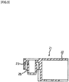
- a joint of the invention illustrated in FIG. 1 to FIG. 4 includes a first joint member 11, which is integrally formed by a frame insertion port 12 facing a horizontal direction with a female coupling port 13 facing a vertical direction, and a second joint member 21 integrally formed by a frame insertion port 22 facing the horizontal direction with a male coupling port 23 facing the vertical direction.
- An axial direction of the frame insertion port 12 of the first joint member 11 and an axial direction of the female coupling port 13 are in a relationship perpendicular to one another.
- an axial direction of the frame insertion port 22 of the second joint member 21 and an axial direction of the male coupling port 23 are in a relationship perpendicular to one another. End portions of upper frames and end portions of lower frames of the above-described enclosure are inserted into the frame insertion ports 12 and 22 of the first joint member 11 and the second joint member 22 facing the horizontal direction.
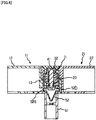
- the female coupling port 13 of the first joint member 11 and the male coupling port 23 of the second joint member 21 are removably engaged via a spring 31.
- the spring 31 is disposed between the female coupling port 13 of the first joint member 11 and the male coupling port 23 of the second joint member 21.
- a bolt 32 is passed from the male coupling port 23 to the female coupling port 13 in an axial direction of the spring 31.
- a distal end portion of the bolt 32 is screwed with and fastened to a screw groove 14, which is disposed at a bottom of the female coupling port 13.
- Teeth rows 15 and 25 are formed at an inner peripheral surface of the female coupling port 13 of the first joint member 11 and an outer peripheral surface of the male coupling port 23 of the second joint member 21 meshing with one another.
- the female coupling port 13 is formed into a cylindrical shape, and the teeth row 15 along the axial direction is formed on the inner peripheral surface of the female coupling port 13.
- the female coupling port 23 is formed into a cylindrical shape with a diameter slightly smaller than the female coupling port 13, and the teeth row 25 along the axial direction is formed on the outer peripheral surface of the female coupling port 23.
- the male coupling port 23 is inserted into the female coupling port 13 and the teeth rows of both are meshed, the horizontal direction where the frame insertion port 22 of the second joint member 21 faces relative to the frame insertion port 12 of the first joint member 11 is changeable depending on the meshing positions of both.
- the first joint member 11 further includes an auxiliary frame insertion port 16 integrally formed opposed to the female coupling port 13.
- An auxiliary frame coupling pipe 51 is removably engaged with the auxiliary frame insertion port.
- the cylindrical auxiliary frame insertion port 16 is integrally formed coaxially opposed to the female coupling port 13 of the first joint member 11.
- the cylindrical auxiliary frame coupling pipe 51 with a diameter slightly smaller than the auxiliary frame insertion port 16 is inserted into the auxiliary frame insertion port 16.
- a V-shaped leaf spring 52 is pushed into the auxiliary frame coupling pipe 51, and hemispherical protrusions 52a and 52b formed on both end portions are projected from small holes 51a and 51b disposed on the auxiliary frame coupling pipe 51.
- the protrusions 52a and 52b are fitted to small holes 16a and 16b, which are disposed on an inner peripheral surface of the auxiliary frame insertion port 16.
- the auxiliary frame coupling pipe 51 can be removably engaged with the auxiliary frame insertion port 16.
- reference numeral 41 denotes a cap covered on a surface opposed to the male coupling port 23 of the second joint member 21 to cover the spring 31 and the bolt 32.
- the units are structured by mounting a plurality of vertical frames 63... at predetermined intervals between upper horizontal frames 61... and lower horizontal frames 62...
- the units are mutually coupled with joints 10... of the invention, thus assembling the enclosure for baby and infant having a rectangular shape on the plane as a whole.
- the horizontal frames 61 and 61 on the upper side of the units adjacent to the frame insertion ports 12 of the first joint members 11 and the frame insertion ports 22 of the second joint members 21 are inserted.
- the similar work is performed on the lower side of the enclosure for baby and infant as well, thus coupling both units to form almost right angle.
- the units are structured by mounting a plurality of vertical frames 66... at predetermined intervals between upper horizontal frames 64 and 64 and lower horizontal frames 65 and 65.
- the units are mutually linearly coupled with the joints 10... of the invention, thus assembling a part of the enclosure for baby and infant whose entire illustration is omitted.
- the horizontal frames 64 and 64 on the upper side of the units adjacent to the frame insertion ports 12 of the first joint members 11 and the frame insertion ports 22 of the second joint members 21 are inserted.
- the similar work is performed on the lower side of the enclosure for baby and infant as well, thus linearly coupling both units.
- auxiliary frame insertion port 16 is integrally formed with the first joint member 11 and the auxiliary frame coupling pipe 51 is engaged with the auxiliary frame insertion port 16 is used.
- An auxiliary frame 52 is bridged across the auxiliary frame coupling pipes 51 and 51 on both the upper side and the lower side. Excessive gaps between the mutual vertical frames 66 and 66 at parts of the joints 10 and 10 are prevented.
Landscapes
- Engineering & Computer Science (AREA)
- General Engineering & Computer Science (AREA)
- Mechanical Engineering (AREA)
- Health & Medical Sciences (AREA)
- General Health & Medical Sciences (AREA)
- Pediatric Medicine (AREA)
- Mutual Connection Of Rods And Tubes (AREA)
- Standing Axle, Rod, Or Tube Structures Coupled By Welding, Adhesion, Or Deposition (AREA)
- Furniture Connections (AREA)
Applications Claiming Priority (1)
| Application Number | Priority Date | Filing Date | Title |
|---|---|---|---|
| PCT/JP2015/069285 WO2017006390A1 (fr) | 2015-07-03 | 2015-07-03 | Joint universel horizontal |
Publications (3)
| Publication Number | Publication Date |
|---|---|
| EP3318771A1 true EP3318771A1 (fr) | 2018-05-09 |
| EP3318771A4 EP3318771A4 (fr) | 2019-02-27 |
| EP3318771B1 EP3318771B1 (fr) | 2021-03-17 |
Family
ID=55951991
Family Applications (1)
| Application Number | Title | Priority Date | Filing Date |
|---|---|---|---|
| EP15897653.0A Active EP3318771B1 (fr) | 2015-07-03 | 2015-07-03 | Joint universel horizontal |
Country Status (4)
| Country | Link |
|---|---|
| US (1) | US11553804B2 (fr) |
| EP (1) | EP3318771B1 (fr) |
| JP (1) | JP5916267B1 (fr) |
| WO (1) | WO2017006390A1 (fr) |
Families Citing this family (10)
| Publication number | Priority date | Publication date | Assignee | Title |
|---|---|---|---|---|
| US11197560B2 (en) | 2018-05-07 | 2021-12-14 | Wonderland Switzerland Ag | Foldable bassinet |
| CN210300375U (zh) | 2018-05-07 | 2020-04-14 | 明门(中国)幼童用品有限公司 | 可折叠收容装置 |
| USD880994S1 (en) * | 2018-10-29 | 2020-04-14 | Yolon Industrial Inc. | Adjustable joint assembly used for fences |
| CN109915003A (zh) * | 2019-04-25 | 2019-06-21 | 中山市宜洋婴儿用品有限公司 | 一种栅栏及其应用的门栏 |
| US12565745B2 (en) * | 2021-02-05 | 2026-03-03 | Peter Zwierzykowski | Articulating expandable barrier |
| US12285118B2 (en) * | 2022-04-08 | 2025-04-29 | Xiamen Xingshuo Maternal & Child Products Co., Ltd | Playpen component for safe use |
| USD1043315S1 (en) * | 2023-02-21 | 2024-09-24 | Zhongshan Fancyspace Technologies Co., Ltd. | Latch for pet play pen |
| CN116905893A (zh) * | 2023-08-23 | 2023-10-20 | 广州市赛尔实业有限公司 | 一种新型围栏 |
| USD1112161S1 (en) * | 2024-01-11 | 2026-02-10 | John Charles Licitra | Three-way coupler |
| USD1114771S1 (en) * | 2024-01-11 | 2026-02-24 | John Charles Licitra | Four-way coupler |
Family Cites Families (26)
| Publication number | Priority date | Publication date | Assignee | Title |
|---|---|---|---|---|
| US4645183A (en) * | 1982-10-15 | 1987-02-24 | Gerber Products Company | Adjustable enclosure |
| US4614452A (en) * | 1984-02-28 | 1986-09-30 | Wang Cheng H | Angle adjusting device |
| JPS6119116U (ja) * | 1984-07-09 | 1986-02-04 | 松本金属株式会社 | 伸縮できるパイプ |
| US4848818A (en) * | 1988-01-19 | 1989-07-18 | Smith Gordon K | Gutter cleaning tool, with a multi-positional and self-locking joint, that can be remotely operated by hand from an oblique angle |
| US4880331A (en) * | 1988-04-25 | 1989-11-14 | Zun Hong Fu | Releasable swivel lock assembly for a canopy support of a stroller |
| US4929113A (en) * | 1989-05-30 | 1990-05-29 | Sheu Yin Ping | Knuckle joint |
| US5039118A (en) * | 1990-08-22 | 1991-08-13 | Huang Ming Tai | Stroller with an improved connector |
| US5123768A (en) * | 1991-08-06 | 1992-06-23 | Franklin Ronald D | Articulating positioning device for tools |
| US5381570A (en) * | 1993-09-22 | 1995-01-17 | Top Fortune Ltd. | Collapsible baby playing bed |
| US5520474A (en) * | 1994-09-19 | 1996-05-28 | Liu; Yang-Ting | Adjustable coupling |
| JP2873545B2 (ja) * | 1995-01-10 | 1999-03-24 | 株式会社マルサ | 伸縮調整可能なパイプ連結構造 |
| US5661942A (en) * | 1995-08-30 | 1997-09-02 | Palmer; Norwin | Modular connector system for tubular structural members |
| US6595498B1 (en) * | 1998-08-20 | 2003-07-22 | Baby Dan A/S | Fencing device, particularly intended for small children |
| TW494965U (en) * | 2001-07-11 | 2002-07-11 | Demby Dev Co Ltd | Open-close structure for security door balustrade |
| US6629801B2 (en) * | 2001-10-18 | 2003-10-07 | Pao-Hsien Cheng | Position adjusting device for a stroller handle |
| CN2722750Y (zh) * | 2004-05-21 | 2005-09-07 | 明门实业股份有限公司 | 尿布台 |
| DE602004013987D1 (de) * | 2004-11-10 | 2008-07-03 | Black & Decker Inc | Gelenkverbindung und Feststell-/Freigabevorrichtung dafür |
| CN101263309A (zh) * | 2005-09-15 | 2008-09-10 | Igc(澳大利亚)股份有限公司 | 角度可调的连接器 |
| TWM294266U (en) * | 2006-02-17 | 2006-07-21 | Demby Dev Co Ltd | Folding and unfolding device of railing |
| US20070210293A1 (en) * | 2006-03-13 | 2007-09-13 | Shu-Chen Cheng | Fencing device |
| CN201003527Y (zh) * | 2007-01-18 | 2008-01-09 | 明门实业股份有限公司 | 弹簧扣装置 |
| US7887029B2 (en) * | 2007-02-05 | 2011-02-15 | Carlson Pet Products, Inc. | In-house gated safety barrier having customizable layout |
| US7721622B2 (en) * | 2007-05-31 | 2010-05-25 | Chester Wen | Vehicle used handle |
| US7552513B2 (en) * | 2007-09-14 | 2009-06-30 | Shu-Chen Cheng | Barrier hinge assembly |
| US10060468B2 (en) * | 2015-02-04 | 2018-08-28 | Lippert Components, Inc. | Adjustment coupler for awning having articulated support arm |
| US11066870B1 (en) * | 2017-12-19 | 2021-07-20 | Regalo International, Llc | Barrier having upside down joint |
-
2015
- 2015-07-03 EP EP15897653.0A patent/EP3318771B1/fr active Active
- 2015-07-03 WO PCT/JP2015/069285 patent/WO2017006390A1/fr not_active Ceased
- 2015-07-03 JP JP2015542103A patent/JP5916267B1/ja active Active
-
2017
- 2017-12-20 US US15/848,293 patent/US11553804B2/en active Active
Also Published As
| Publication number | Publication date |
|---|---|
| EP3318771A4 (fr) | 2019-02-27 |
| EP3318771B1 (fr) | 2021-03-17 |
| US11553804B2 (en) | 2023-01-17 |
| US20180110344A1 (en) | 2018-04-26 |
| JPWO2017006390A1 (ja) | 2017-07-06 |
| WO2017006390A1 (fr) | 2017-01-12 |
| JP5916267B1 (ja) | 2016-05-11 |
Similar Documents
| Publication | Publication Date | Title |
|---|---|---|
| EP3318771A1 (fr) | Joint universel horizontal | |
| USD882220S1 (en) | Insertable adaptors and adjustable cushioning shoe heel | |
| CN107532684B (zh) | 长条物的引导装置及固定部件 | |
| USD685327S1 (en) | Headphone adapter for a case for an electronic device | |
| EP2629867B1 (fr) | Ensemble de construction de jouet | |
| EP3078333A3 (fr) | Ensemble adaptateur avec support pour interconnecter des dispositifs chirurgicaux electromecaniques et des unites de chargement chirurgical et systemes chirurgicaux associes | |
| US9793638B2 (en) | Plug connector module | |
| PH12016500558A1 (en) | Modular member and stable support body constituted thereby | |
| USD693309S1 (en) | Connector housing | |
| WO2015017806A3 (fr) | Corps de capteur à deux axes pour un transducteur de charge et balance à plateau en étant équipée | |
| USD852685S1 (en) | Suspension stabilizer bar endlink assembly | |
| EP3015149A2 (fr) | Joint et ensemble de joint ayant le même appareil | |
| CN102458511B (zh) | 将外部功能性装置卡扣于处理设备的扣持装置、外部功能性装置及处理设备 | |
| MY181686A (en) | Medical valve | |
| MX2018011173A (es) | Junta de rotula y enlace estabilizador usando la misma. | |
| EP3182181A3 (fr) | Connecteurs optiques de panneau arrière et connexions optiques les incorporant | |
| MX357023B (es) | Dispositivo y método para anastomosis. | |
| KR20130127462A (ko) | 완구 조립 세트 | |
| US20170295956A1 (en) | Structural connector and structural system | |
| USD919080S1 (en) | Breathing tube connector for a respiratory gas exchange monitor | |
| TWM473283U (zh) | 工具接頭結構 | |
| EP2927719A1 (fr) | Ensemble de connecteur de fibres optiques | |
| USD837199S1 (en) | Joint member for a mounting unit for audiovisual devices | |
| RU2007117665A (ru) | Агрегат стыковочный пассивный | |
| CN201407251Y (zh) | 连接件 |
Legal Events
| Date | Code | Title | Description |
|---|---|---|---|
| STAA | Information on the status of an ep patent application or granted ep patent |
Free format text: STATUS: THE INTERNATIONAL PUBLICATION HAS BEEN MADE |
|
| PUAI | Public reference made under article 153(3) epc to a published international application that has entered the european phase |
Free format text: ORIGINAL CODE: 0009012 |
|
| STAA | Information on the status of an ep patent application or granted ep patent |
Free format text: STATUS: REQUEST FOR EXAMINATION WAS MADE |
|
| 17P | Request for examination filed |
Effective date: 20180205 |
|
| AK | Designated contracting states |
Kind code of ref document: A1 Designated state(s): AL AT BE BG CH CY CZ DE DK EE ES FI FR GB GR HR HU IE IS IT LI LT LU LV MC MK MT NL NO PL PT RO RS SE SI SK SM TR |
|
| AX | Request for extension of the european patent |
Extension state: BA ME |
|
| DAV | Request for validation of the european patent (deleted) | ||
| DAX | Request for extension of the european patent (deleted) | ||
| A4 | Supplementary search report drawn up and despatched |
Effective date: 20190125 |
|
| RIC1 | Information provided on ipc code assigned before grant |
Ipc: F16B 7/04 20060101AFI20190121BHEP Ipc: F16B 7/20 20060101ALI20190121BHEP Ipc: F16B 7/14 20060101ALI20190121BHEP Ipc: A47D 13/06 20060101ALI20190121BHEP |
|
| STAA | Information on the status of an ep patent application or granted ep patent |
Free format text: STATUS: EXAMINATION IS IN PROGRESS |
|
| 17Q | First examination report despatched |
Effective date: 20200626 |
|
| GRAP | Despatch of communication of intention to grant a patent |
Free format text: ORIGINAL CODE: EPIDOSNIGR1 |
|
| STAA | Information on the status of an ep patent application or granted ep patent |
Free format text: STATUS: GRANT OF PATENT IS INTENDED |
|
| RIC1 | Information provided on ipc code assigned before grant |
Ipc: F16B 7/04 20060101AFI20201002BHEP Ipc: F16B 7/18 20060101ALI20201002BHEP |
|
| INTG | Intention to grant announced |
Effective date: 20201029 |
|
| GRAS | Grant fee paid |
Free format text: ORIGINAL CODE: EPIDOSNIGR3 |
|
| GRAA | (expected) grant |
Free format text: ORIGINAL CODE: 0009210 |
|
| STAA | Information on the status of an ep patent application or granted ep patent |
Free format text: STATUS: THE PATENT HAS BEEN GRANTED |
|
| AK | Designated contracting states |
Kind code of ref document: B1 Designated state(s): AL AT BE BG CH CY CZ DE DK EE ES FI FR GB GR HR HU IE IS IT LI LT LU LV MC MK MT NL NO PL PT RO RS SE SI SK SM TR |
|
| REG | Reference to a national code |
Ref country code: GB Ref legal event code: FG4D |
|
| REG | Reference to a national code |
Ref country code: CH Ref legal event code: EP |
|
| REG | Reference to a national code |
Ref country code: DE Ref legal event code: R096 Ref document number: 602015067117 Country of ref document: DE |
|
| REG | Reference to a national code |
Ref country code: IE Ref legal event code: FG4D |
|
| REG | Reference to a national code |
Ref country code: AT Ref legal event code: REF Ref document number: 1372496 Country of ref document: AT Kind code of ref document: T Effective date: 20210415 |
|
| REG | Reference to a national code |
Ref country code: SE Ref legal event code: TRGR |
|
| REG | Reference to a national code |
Ref country code: LT Ref legal event code: MG9D |
|
| PG25 | Lapsed in a contracting state [announced via postgrant information from national office to epo] |
Ref country code: FI Free format text: LAPSE BECAUSE OF FAILURE TO SUBMIT A TRANSLATION OF THE DESCRIPTION OR TO PAY THE FEE WITHIN THE PRESCRIBED TIME-LIMIT Effective date: 20210317 Ref country code: HR Free format text: LAPSE BECAUSE OF FAILURE TO SUBMIT A TRANSLATION OF THE DESCRIPTION OR TO PAY THE FEE WITHIN THE PRESCRIBED TIME-LIMIT Effective date: 20210317 Ref country code: GR Free format text: LAPSE BECAUSE OF FAILURE TO SUBMIT A TRANSLATION OF THE DESCRIPTION OR TO PAY THE FEE WITHIN THE PRESCRIBED TIME-LIMIT Effective date: 20210618 Ref country code: BG Free format text: LAPSE BECAUSE OF FAILURE TO SUBMIT A TRANSLATION OF THE DESCRIPTION OR TO PAY THE FEE WITHIN THE PRESCRIBED TIME-LIMIT Effective date: 20210617 Ref country code: NO Free format text: LAPSE BECAUSE OF FAILURE TO SUBMIT A TRANSLATION OF THE DESCRIPTION OR TO PAY THE FEE WITHIN THE PRESCRIBED TIME-LIMIT Effective date: 20210617 |
|
| REG | Reference to a national code |
Ref country code: AT Ref legal event code: MK05 Ref document number: 1372496 Country of ref document: AT Kind code of ref document: T Effective date: 20210317 |
|
| REG | Reference to a national code |
Ref country code: NL Ref legal event code: MP Effective date: 20210317 |
|
| PG25 | Lapsed in a contracting state [announced via postgrant information from national office to epo] |
Ref country code: RS Free format text: LAPSE BECAUSE OF FAILURE TO SUBMIT A TRANSLATION OF THE DESCRIPTION OR TO PAY THE FEE WITHIN THE PRESCRIBED TIME-LIMIT Effective date: 20210317 Ref country code: LV Free format text: LAPSE BECAUSE OF FAILURE TO SUBMIT A TRANSLATION OF THE DESCRIPTION OR TO PAY THE FEE WITHIN THE PRESCRIBED TIME-LIMIT Effective date: 20210317 |
|
| PG25 | Lapsed in a contracting state [announced via postgrant information from national office to epo] |
Ref country code: NL Free format text: LAPSE BECAUSE OF FAILURE TO SUBMIT A TRANSLATION OF THE DESCRIPTION OR TO PAY THE FEE WITHIN THE PRESCRIBED TIME-LIMIT Effective date: 20210317 |
|
| PG25 | Lapsed in a contracting state [announced via postgrant information from national office to epo] |
Ref country code: EE Free format text: LAPSE BECAUSE OF FAILURE TO SUBMIT A TRANSLATION OF THE DESCRIPTION OR TO PAY THE FEE WITHIN THE PRESCRIBED TIME-LIMIT Effective date: 20210317 Ref country code: CZ Free format text: LAPSE BECAUSE OF FAILURE TO SUBMIT A TRANSLATION OF THE DESCRIPTION OR TO PAY THE FEE WITHIN THE PRESCRIBED TIME-LIMIT Effective date: 20210317 Ref country code: LT Free format text: LAPSE BECAUSE OF FAILURE TO SUBMIT A TRANSLATION OF THE DESCRIPTION OR TO PAY THE FEE WITHIN THE PRESCRIBED TIME-LIMIT Effective date: 20210317 Ref country code: SM Free format text: LAPSE BECAUSE OF FAILURE TO SUBMIT A TRANSLATION OF THE DESCRIPTION OR TO PAY THE FEE WITHIN THE PRESCRIBED TIME-LIMIT Effective date: 20210317 Ref country code: AT Free format text: LAPSE BECAUSE OF FAILURE TO SUBMIT A TRANSLATION OF THE DESCRIPTION OR TO PAY THE FEE WITHIN THE PRESCRIBED TIME-LIMIT Effective date: 20210317 |
|
| PG25 | Lapsed in a contracting state [announced via postgrant information from national office to epo] |
Ref country code: PL Free format text: LAPSE BECAUSE OF FAILURE TO SUBMIT A TRANSLATION OF THE DESCRIPTION OR TO PAY THE FEE WITHIN THE PRESCRIBED TIME-LIMIT Effective date: 20210317 Ref country code: PT Free format text: LAPSE BECAUSE OF FAILURE TO SUBMIT A TRANSLATION OF THE DESCRIPTION OR TO PAY THE FEE WITHIN THE PRESCRIBED TIME-LIMIT Effective date: 20210719 Ref country code: SK Free format text: LAPSE BECAUSE OF FAILURE TO SUBMIT A TRANSLATION OF THE DESCRIPTION OR TO PAY THE FEE WITHIN THE PRESCRIBED TIME-LIMIT Effective date: 20210317 Ref country code: RO Free format text: LAPSE BECAUSE OF FAILURE TO SUBMIT A TRANSLATION OF THE DESCRIPTION OR TO PAY THE FEE WITHIN THE PRESCRIBED TIME-LIMIT Effective date: 20210317 Ref country code: IS Free format text: LAPSE BECAUSE OF FAILURE TO SUBMIT A TRANSLATION OF THE DESCRIPTION OR TO PAY THE FEE WITHIN THE PRESCRIBED TIME-LIMIT Effective date: 20210717 |
|
| REG | Reference to a national code |
Ref country code: DE Ref legal event code: R097 Ref document number: 602015067117 Country of ref document: DE |
|
| PLBE | No opposition filed within time limit |
Free format text: ORIGINAL CODE: 0009261 |
|
| STAA | Information on the status of an ep patent application or granted ep patent |
Free format text: STATUS: NO OPPOSITION FILED WITHIN TIME LIMIT |
|
| PG25 | Lapsed in a contracting state [announced via postgrant information from national office to epo] |
Ref country code: DK Free format text: LAPSE BECAUSE OF FAILURE TO SUBMIT A TRANSLATION OF THE DESCRIPTION OR TO PAY THE FEE WITHIN THE PRESCRIBED TIME-LIMIT Effective date: 20210317 Ref country code: AL Free format text: LAPSE BECAUSE OF FAILURE TO SUBMIT A TRANSLATION OF THE DESCRIPTION OR TO PAY THE FEE WITHIN THE PRESCRIBED TIME-LIMIT Effective date: 20210317 Ref country code: ES Free format text: LAPSE BECAUSE OF FAILURE TO SUBMIT A TRANSLATION OF THE DESCRIPTION OR TO PAY THE FEE WITHIN THE PRESCRIBED TIME-LIMIT Effective date: 20210317 |
|
| 26N | No opposition filed |
Effective date: 20211220 |
|
| PG25 | Lapsed in a contracting state [announced via postgrant information from national office to epo] |
Ref country code: SI Free format text: LAPSE BECAUSE OF FAILURE TO SUBMIT A TRANSLATION OF THE DESCRIPTION OR TO PAY THE FEE WITHIN THE PRESCRIBED TIME-LIMIT Effective date: 20210317 |
|
| REG | Reference to a national code |
Ref country code: CH Ref legal event code: PL |
|
| PG25 | Lapsed in a contracting state [announced via postgrant information from national office to epo] |
Ref country code: MC Free format text: LAPSE BECAUSE OF FAILURE TO SUBMIT A TRANSLATION OF THE DESCRIPTION OR TO PAY THE FEE WITHIN THE PRESCRIBED TIME-LIMIT Effective date: 20210317 |
|
| REG | Reference to a national code |
Ref country code: BE Ref legal event code: MM Effective date: 20210731 |
|
| PG25 | Lapsed in a contracting state [announced via postgrant information from national office to epo] |
Ref country code: LI Free format text: LAPSE BECAUSE OF NON-PAYMENT OF DUE FEES Effective date: 20210731 Ref country code: IT Free format text: LAPSE BECAUSE OF FAILURE TO SUBMIT A TRANSLATION OF THE DESCRIPTION OR TO PAY THE FEE WITHIN THE PRESCRIBED TIME-LIMIT Effective date: 20210317 Ref country code: CH Free format text: LAPSE BECAUSE OF NON-PAYMENT OF DUE FEES Effective date: 20210731 |
|
| PG25 | Lapsed in a contracting state [announced via postgrant information from national office to epo] |
Ref country code: IS Free format text: LAPSE BECAUSE OF FAILURE TO SUBMIT A TRANSLATION OF THE DESCRIPTION OR TO PAY THE FEE WITHIN THE PRESCRIBED TIME-LIMIT Effective date: 20210717 Ref country code: LU Free format text: LAPSE BECAUSE OF NON-PAYMENT OF DUE FEES Effective date: 20210703 |
|
| PG25 | Lapsed in a contracting state [announced via postgrant information from national office to epo] |
Ref country code: IE Free format text: LAPSE BECAUSE OF NON-PAYMENT OF DUE FEES Effective date: 20210703 Ref country code: BE Free format text: LAPSE BECAUSE OF NON-PAYMENT OF DUE FEES Effective date: 20210731 |
|
| PG25 | Lapsed in a contracting state [announced via postgrant information from national office to epo] |
Ref country code: HU Free format text: LAPSE BECAUSE OF FAILURE TO SUBMIT A TRANSLATION OF THE DESCRIPTION OR TO PAY THE FEE WITHIN THE PRESCRIBED TIME-LIMIT; INVALID AB INITIO Effective date: 20150703 |
|
| PG25 | Lapsed in a contracting state [announced via postgrant information from national office to epo] |
Ref country code: CY Free format text: LAPSE BECAUSE OF FAILURE TO SUBMIT A TRANSLATION OF THE DESCRIPTION OR TO PAY THE FEE WITHIN THE PRESCRIBED TIME-LIMIT Effective date: 20210317 |
|
| PG25 | Lapsed in a contracting state [announced via postgrant information from national office to epo] |
Ref country code: MK Free format text: LAPSE BECAUSE OF FAILURE TO SUBMIT A TRANSLATION OF THE DESCRIPTION OR TO PAY THE FEE WITHIN THE PRESCRIBED TIME-LIMIT Effective date: 20210317 |
|
| PG25 | Lapsed in a contracting state [announced via postgrant information from national office to epo] |
Ref country code: MT Free format text: LAPSE BECAUSE OF FAILURE TO SUBMIT A TRANSLATION OF THE DESCRIPTION OR TO PAY THE FEE WITHIN THE PRESCRIBED TIME-LIMIT Effective date: 20210317 |
|
| PGFP | Annual fee paid to national office [announced via postgrant information from national office to epo] |
Ref country code: DE Payment date: 20250728 Year of fee payment: 11 |
|
| PGFP | Annual fee paid to national office [announced via postgrant information from national office to epo] |
Ref country code: GB Payment date: 20250722 Year of fee payment: 11 |
|
| PGFP | Annual fee paid to national office [announced via postgrant information from national office to epo] |
Ref country code: FR Payment date: 20250725 Year of fee payment: 11 |
|
| PGFP | Annual fee paid to national office [announced via postgrant information from national office to epo] |
Ref country code: SE Payment date: 20250725 Year of fee payment: 11 |
|
| PG25 | Lapsed in a contracting state [announced via postgrant information from national office to epo] |
Ref country code: TR Free format text: LAPSE BECAUSE OF FAILURE TO SUBMIT A TRANSLATION OF THE DESCRIPTION OR TO PAY THE FEE WITHIN THE PRESCRIBED TIME-LIMIT Effective date: 20210317 |