EP3330041B1 - Spannvorrichtung mit spannbuchse - Google Patents
Spannvorrichtung mit spannbuchse Download PDFInfo
- Publication number
- EP3330041B1 EP3330041B1 EP17207353.8A EP17207353A EP3330041B1 EP 3330041 B1 EP3330041 B1 EP 3330041B1 EP 17207353 A EP17207353 A EP 17207353A EP 3330041 B1 EP3330041 B1 EP 3330041B1
- Authority
- EP
- European Patent Office
- Prior art keywords
- clamping
- tension rod
- bushing
- clamping bushing
- bore
- Prior art date
- Legal status (The legal status is an assumption and is not a legal conclusion. Google has not performed a legal analysis and makes no representation as to the accuracy of the status listed.)
- Active
Links
Images


Classifications
-
- B—PERFORMING OPERATIONS; TRANSPORTING
- B23—MACHINE TOOLS; METAL-WORKING NOT OTHERWISE PROVIDED FOR
- B23B—TURNING; BORING
- B23B31/00—Chucks; Expansion mandrels; Adaptations thereof for remote control
- B23B31/40—Expansion mandrels
- B23B31/4006—Gripping the work or tool by a split sleeve
- B23B31/4013—Details of the jaws
-
- B—PERFORMING OPERATIONS; TRANSPORTING
- B23—MACHINE TOOLS; METAL-WORKING NOT OTHERWISE PROVIDED FOR
- B23B—TURNING; BORING
- B23B31/00—Chucks; Expansion mandrels; Adaptations thereof for remote control
- B23B31/40—Expansion mandrels
- B23B31/4006—Gripping the work or tool by a split sleeve
- B23B31/402—Gripping the work or tool by a split sleeve using fluid-pressure means to actuate the gripping means
-
- B—PERFORMING OPERATIONS; TRANSPORTING
- B23—MACHINE TOOLS; METAL-WORKING NOT OTHERWISE PROVIDED FOR
- B23Q—DETAILS, COMPONENTS, OR ACCESSORIES FOR MACHINE TOOLS, e.g. ARRANGEMENTS FOR COPYING OR CONTROLLING; MACHINE TOOLS IN GENERAL CHARACTERISED BY THE CONSTRUCTION OF PARTICULAR DETAILS OR COMPONENTS; COMBINATIONS OR ASSOCIATIONS OF METAL-WORKING MACHINES, NOT DIRECTED TO A PARTICULAR RESULT
- B23Q1/00—Members which are comprised in the general build-up of a form of machine, particularly relatively large fixed members
- B23Q1/0063—Connecting non-slidable parts of machine tools to each other
- B23Q1/0081—Connecting non-slidable parts of machine tools to each other using an expanding clamping member insertable in a receiving hole
- B23Q1/009—Connecting non-slidable parts of machine tools to each other using an expanding clamping member insertable in a receiving hole the receiving hole being cylindrical or conical
-
- B—PERFORMING OPERATIONS; TRANSPORTING
- B23—MACHINE TOOLS; METAL-WORKING NOT OTHERWISE PROVIDED FOR
- B23Q—DETAILS, COMPONENTS, OR ACCESSORIES FOR MACHINE TOOLS, e.g. ARRANGEMENTS FOR COPYING OR CONTROLLING; MACHINE TOOLS IN GENERAL CHARACTERISED BY THE CONSTRUCTION OF PARTICULAR DETAILS OR COMPONENTS; COMBINATIONS OR ASSOCIATIONS OF METAL-WORKING MACHINES, NOT DIRECTED TO A PARTICULAR RESULT
- B23Q3/00—Devices holding, supporting, or positioning work or tools, of a kind normally removable from the machine
- B23Q3/02—Devices holding, supporting, or positioning work or tools, of a kind normally removable from the machine for mounting on a work-table, tool-slide, or analogous part
- B23Q3/06—Work-clamping means
-
- B—PERFORMING OPERATIONS; TRANSPORTING
- B25—HAND TOOLS; PORTABLE POWER-DRIVEN TOOLS; MANIPULATORS
- B25B—TOOLS OR BENCH DEVICES NOT OTHERWISE PROVIDED FOR, FOR FASTENING, CONNECTING, DISENGAGING OR HOLDING
- B25B5/00—Clamps
- B25B5/06—Arrangements for positively actuating jaws
- B25B5/061—Arrangements for positively actuating jaws with fluid drive
-
- B—PERFORMING OPERATIONS; TRANSPORTING
- B25—HAND TOOLS; PORTABLE POWER-DRIVEN TOOLS; MANIPULATORS
- B25B—TOOLS OR BENCH DEVICES NOT OTHERWISE PROVIDED FOR, FOR FASTENING, CONNECTING, DISENGAGING OR HOLDING
- B25B5/00—Clamps
- B25B5/16—Details, e.g. jaws, jaw attachments
- B25B5/163—Jaws or jaw attachments
-
- B—PERFORMING OPERATIONS; TRANSPORTING
- B23—MACHINE TOOLS; METAL-WORKING NOT OTHERWISE PROVIDED FOR
- B23B—TURNING; BORING
- B23B2231/00—Details of chucks, toolholder shanks or tool shanks
- B23B2231/34—Jaws
- B23B2231/342—Padded or cushioned jaws
-
- B—PERFORMING OPERATIONS; TRANSPORTING
- B23—MACHINE TOOLS; METAL-WORKING NOT OTHERWISE PROVIDED FOR
- B23B—TURNING; BORING
- B23B2260/00—Details of constructional elements
- B23B2260/138—Screw threads
Definitions
- the invention relates to a clamping device for the mechanical clamping of a component, in particular a workpiece to be clamped, according to the preamble of claim 1.
- a clamping device is for example from the EP 2 594 359 A1 out.
- clamping devices which have a pneumatically or hydraulically displaceable tie rod (clamping bolt), which can be introduced with its free end into a corresponding blind bore in the component to be clamped.
- the free end of the tie rod expands conically towards its end and is surrounded by a clamping bush, which is introduced together with the free end of the tie rod in the blind hole of the component to be clamped.
- the clamping bush Upon retraction of the tie rod, the clamping bush then initially remains in its position, so that the retraction of the tie rod due to the conical widening of the free end of the tie rod leads to a radial expansion of the clamping bush and thus to a clamping of the component.
- a disadvantage of the known tensioning devices is the time-consuming disassembly of the tie rod.
- the invention is therefore based on the object to provide an improved clamping device.
- the clamping device according to the invention initially has an axially displaceable tie rod (clamping bolt) for clamping the component, wherein the operation of such a tie rod already described above. Furthermore, the clamping device according to the invention comprises an axially displaceable piston for displacing the tie rod, wherein the piston can be driven, for example hydraulically, pneumatically, by electric motor or manually-mechanically.
- the tensioning device has a clamping bushing as described above, wherein the tensioning armature extends axially through the tensioning bushing and has a radial expansion at its free end, so that the tensioning rod radially expands the tensioning bushing when the tensioning rod is retracted ,
- the clamping bush thus - as described above - a positive connection between the clamping bush and the blind bore in the exciting part ago.
- the invention is not limited to clamping devices with clamping bushes, which produce a positive connection to the component to be clamped.
- the invention also includes clamping devices with clamping bushes, which produce a frictional connection to the blind hole in the component to be clamped in a conventional manner.
- the invention is thus applicable to components with cylindrical blind holes, conical blind holes or blind holes with an internal thread.
- the tie rod is releasably anchored in the piston by a bayonet lock. This means that the tie rod inserted in a certain rotational position with respect to its longitudinal axis in the jig or from it can be removed. The anchoring of the tie rod then takes place in the inserted state by the tie rod is rotated about its longitudinal axis, for example by 90 °.
- An advantage of such a bayonet lock for the tie rod is the fact that no replacement of the tie rod is required to replace the tie rod.
- the tie rod can be replaced in this way directly on the jig. It should be mentioned that the replacement of the tie rod can preferably be done without affecting fluid lines (eg hydraulic lines) to drive the piston, so that when replacing the tie rod there is no risk that hydraulic fluid leaks.
- the tie rod has a hammer-shaped lateral extension at its lower end.
- the piston and the clamping device on an axial bore, through which the tie rod can be inserted.
- This axial bore is a slot in cross section, so that the tie rod can be inserted despite the hammer-shaped lateral extension.
- a first spring is provided, which biases the tie rod to avoid falling out of the tie rod from the tensioning device.
- the bayonet lock between the tie rod and the piston on a rotational angle limiting which limits the angle of rotation of the tie rod.
- this rotation angle limitation acts in both directions of rotation and has this each have a rotation angle stop.
- the angle of rotation stop consist of a pin which is inserted into a corresponding bore in the piston.
- the bayonet lock preferably has a security against rotation in order to prevent an unintentional solution of the bayonet closure.
- this rotation can have a rotation angle stop, which prevents the tie rod can turn independently in a position that allows release of the bayonet lock and thus pulling out the tie rod.
- the angle of rotation stop for example, have a pin which is inserted into a corresponding bore in the piston.
- the invention also includes the general technical teaching to provide for clamping a positive connection between the outer surface of the clamping bush and the inner wall of the blind bore in the component to be clamped.
- the positive connection between the clamping bush and component consists of a threaded connection.
- the outer surface of the clamping bush on an external thread which engages in a correspondingly adapted internal thread in the inner wall of the blind bore of the component and thereby produces the positive connection between the clamping bush and component.
- the external thread of the clamping bush and the internal thread of the component preferably have the same thread pitch to allow a positive threaded engagement.
- clamping bush can be widened in the radial direction as in the conventional clamping bush described above, wherein the clamping bush in the radially contracted state (relaxed state) does not form a positive connection with the component, whereas the clamping bush in the radially expanded state form fit into the Component engages.
- the external thread of the clamping bush in the radially contracted state usually has a smaller thread diameter than the internal thread of the bore, so that the clamping bush can then be introduced without problems in the blind bore in the component.
- the external thread of the clamping bush preferably has the same thread diameter as the internal thread of the bore, so that external thread and internal thread then engage with each other and form the positive connection.
- the outer diameter of the male thread (i.e., tip to tip) of the collet in the radially contracted state of the collet is preferably smaller than the core diameter of the internal thread of the bore. This is useful so that the clamping bush can be introduced in the radially contracted state in the blind bore of the component.
- the radially contracted state is usually a relaxed state of the tensioning device, ie without a radial expansion by the tie rod.
- the radial expanded state of the clamping sleeve is usually not the normal state of the clamping bush. Rather, the clamping bush takes on the radially expanded state only when the clamping bush is radially expanded by the tie rod.
- the radial expansion of the clamping bush is made possible by a special construction.
- the clamping bush has a plurality of segments which are distributed over the circumference of the clamping bush.
- the adjacent segments of the clamping bush are in each case separated from one another by an axially extending slot, wherein the individual slots each extend from the free end of the clamping bushing over at least part of the axial length of the clamping bush.
- This slotted arrangement allows the individual segments of the clamping bush to rebound in the radial direction to allow radial expansion of the clamping bush.
- the clamping bush preferably has an axial through hole for the tie rod like the conventional clamping bush, wherein the through hole preferably widens radially towards the free end of the clamping bush, in particular in a conical shape.
- the piston and thus also the tie rod is preferably driven hydraulically or pneumatically.
- the tensioning device therefore, preferably has two pressure chambers, namely a first pressure chamber for hydraulic or pneumatic pressurization of the piston for tensioning the tie rod and a second pressure chamber for hydraulic or pneumatic pressurization of the piston to relax the tie rod.
- the first pressure chamber for tensioning the tie rod is usually arranged above the piston and therefore presses the piston and thus also the tie rod preferably downwards.
- the second pressure chamber for relaxing the tie rod is preferably disposed below the piston and therefore preferably pushes the piston to relax upwards.
- the tensioning device has a so-called intrinsic safety device, which ensures that the component remains tensioned in the event of a pressure failure.
- a second spring may be provided, which biases the piston and thus also the tie rod in the clamping position.
- the second spring pulls the piston and thus also the tie rod down, whereby the clamping bush is radially expanded and thereby produces a frictional and / or positive connection with the component to be clamped.
- such an interrogator operates pneumatically.
- the interrogator can blow out compressed air from the bearing surface of the clamping device. With a support of a component on the support surface, the component then blocks the outlet opening, which manifests itself in a corresponding change of pressure and flow and thus can be detected metrologically.
- the compressed air from the interrogator can also be introduced into the cylinder, in which the piston is displaceable. This allows a detection of the piston position, since the piston can release the bore, for example, in the maximum tensioned state or a fracture of the tie rod, which in turn manifests itself in a corresponding change of pressure or flow of compressed air and thus can be detected metrologically.
- the tensioning device preferably comprises a blocking air device for blowing out sealing air in the region of a support around the free end of the tie rod.
- the sealing air should ensure that the contact area of the clamping device remains clean.
- the compressed air from the blocking air device can also be introduced into the cylinder, in which the piston is displaceable. In a relaxed position, the pressure in this line increases through the existing throttle. This allows a query of the relaxation position. The workpiece can thus be removed from the device. In tense Position enters the air through the holes 48 and 52 (see. FIGS. 4 and 5 ) with a larger volume (pressure difference is measurable).
- the clamping device preferably has an elastic centering element in order to effect a pre-centering of the tie rod in the tensioning device.
- the centering element is an elastic O-ring, which surrounds the tie rod in an annular manner, so that a radial deflection of the tie rod leads to a centering counterforce through the O-ring.
- the centering element (for example O-ring) is arranged below the clamping bush and surrounds only the tie rod, wherein the centering element bears directly against the lateral surface of the tie rod.
- the centering element for example, O-ring
- the tensioning device can preferably perform two axial movements, namely on the one hand a tensioning movement and on the other hand a downwards movement.
- the clamping movement serves exclusively to radially expand the clamping bush and thereby produce a frictional or positive connection between the clamping bush and the component to be clamped.
- the component to be clamped is not yet moved itself.
- an axial pull-down movement wherein the now-tensioned component is pulled axially against the clamping device to adjust a defined position of the component.
- the clamping bush in the clamping device is preferably mounted with an axial clearance, so that the clamping bush can perform the axial down movement together with the tensioned component.
- a third spring is provided for biasing the clamping bush against the pull-down movement.
- the third spring thus presses the clamping bush upward, so that the tie rod must overcome the spring force of the third spring in the pull-down movement.
- the third spring ensures during the previous tensioning movement of the tie rod that the clamping bush does not yield axially, but is radially expanded.
- the third spring thus provides sufficient resistance so that the clamping bush does not yield axially when the tie rod is pulled down, but widens radially.
- the third spring is so yielding that the expanded clamping bushing can perform a down movement together with the tensioned component.
- the clamping bush has a radially projecting collar at the bottom, the third spring surrounding the radially projecting collar on the outside and pressing radially inward. The force acting on the radially projecting collar and inwardly directed clamping force is then converted into the clamping bushing in a corresponding axially directed force, which presses the clamping sleeve upwards.
- the third spring is arranged under the clamping bush and presses the clamping sleeve axially upwards.
- the clamping bush on its underside on a conical ramp surface, which tapers conically upwards.
- the clamping bush lies here with its conical ramp surface on a fixed in the clamping device and complementary inclined conical ramp surface. The sliding together of the conical ramp surfaces then leads in a clamping operation to a radial expansion of the clamping bush and then during the pull-down movement also to an axial downward movement.
- FIGS. 1A to 8 show different views of a clamping device 1 according to the invention for clamping a component 2, wherein the component 2 only in FIG. 2 is shown schematically and is omitted otherwise for the sake of clarity.
- the component 2 has for engagement by the clamping device 1 on a blind bore 3 with an inner wall 4, which is provided with an internal thread 5, to allow a positive engagement, as will be described in detail.
- the tensioning device 1 has a housing 6, which is closed at the top by a housing cover 7 and at the bottom by a housing bottom 8.
- the annular gap between the housing bottom 8 and the housing 6 is sealed by a seal 9.
- a tie rod 10 is arranged axially displaceable, wherein the tie rod 10 can be moved by a likewise axially displaceable piston 11, as will also be described in detail.
- the annular gap between the outer circumferential surface of the piston 11 and the inner wall of the housing 6 is in this case by two seals 12, 13 sealed.
- the piston 11 has an axial through-bore 14 through which the lower end of the tie rod 10 is passed, the tie rod 10 being anchored in the piston 11 by a detachable bayonet catch, as will be described in detail below.
- a piston insert 15 is inserted below, with a spring 16 is supported at the bottom of the piston insert 15, which presses the tie rod 10 axially upward so that the bayonet lock of the tie rod 10 does not accidentally dissolves.
- the through hole 14 in the piston 11 is in this case designed in cross section as a slot, as from FIG. 7 is apparent.
- the tie rod 10 has at its lower end a hammer-shaped lateral extension 17, which is supported in the anchored state of the bayonet lock at the bottom of projections 53 in the piston 11. In a certain angular position of the tie rod 10 can thus be easily inserted into the clamping device 1, since the formed as an elongated hole through hole 14 then provides sufficient space. After insertion of the tie rod 10, the tie rod 10 is then rotated by 90 °, whereupon the tie rod 10 is supported with its hammer-shaped extension 17 on the piston 11.
- attachment e.g. via swivel cam or stop bolt.
- the spring 16 prevents this that the tie rod 10 unintentionally rotates and then fall out of the jig 1 could (snaps on the projection 53).
- the clamping device 1 in the upper region on an inner part 18 which surrounds the tie rod 10 annular and contains a through hole in which an O-ring 19 is arranged for pre-centering of the tie rod 10.
- the O-ring 19 exerts namely an inwardly directed counterforce, whereby the tie rod 10 is centered in the tensioning device 1.
- the inner part 18 is supported on the housing 6 via a compression spring 20.
- the compression spring 20 pushes the inner part 18 so upwards.
- the free end of the tie rod 10 is surrounded by a clamping sleeve 21, wherein the clamping bush 21 is introduced during clamping of the component 2 in the blind bore 3 and then produces a positive connection.
- the clamping bush 21 on its outer lateral surface on an external thread, which is adapted to the internal thread 5 of the blind bore 3.
- the free end of the tie rod 10 has an outer circumferential surface, the conical to the end of the tie rod 10 (alternatively also pyramid surfaces are possible) extended. Accordingly, the clamping bush 21 has a conical inner wall, which widens conically towards the free end. Retraction of the tie rod 10 into the tensioning device 1 therefore results, on the one hand, and because of the successive sliding conical surfaces of the tie rod 10, on the one hand, and the clamping bush 21 on the other hand, that the tension bushing 21 expands radially. The external thread of the clamping bush 21 then engages in the correspondingly adapted internal thread 5 of the blind bore 3 and thereby produces a positive connection.
- clamping bush 21 is surrounded on the outside by an annular scraper 22.
- the scraper 22 prevents dirt from entering the clamping device 1.
- FIG. 2 shows a cross-sectional view of the clamping device 1 with a hydraulic connection 23 for tensioning the tie rod 10.
- the hydraulic port 23 is connected via oil passages 24, 25 with a pressure chamber 26, wherein the hydraulic pressure acting in the pressure chamber 26 presses from above on the piston 11 and the piston 11th if necessary press down.
- the piston 11 then takes the tie rod 10 down with accordingly.
- the oil channel 25 is closed at its upper side by a plug 27.
- FIG. 3 shows another cross-sectional view of the clamping device of the Figures 1A and 1B
- the hydraulic connection 28 is connected via oil passages 29, 30 to a pressure chamber 31, wherein the pressure prevailing in the pressure chamber 31 oil pressure acts from below on the piston 11 and thereby pushes the piston 11 upwards.
- the oil passage 30 is also closed at its top by a plug 32.
- FIG. 4 shows a further cross-sectional view of the clamping device 1 with a further pneumatic connection 33 for a blocking air device and a query of the release position of the piston (11).
- the pneumatic connection 33 is connected via compressed air channels 34, 35, 36, 48 to a pressure chamber 37 in the housing cover 7, from where the compressed air can be blown out through blow-out openings to the support area to keep the clamping device 1 clean.
- the compressed air channel 34 is closed on the outside by a plug 38.
- a throttle 49 ensures a pressure difference.
- the piston 11 In the relaxed state, the piston 11 is closed in its upper position and the compressed air channel 48 (sealing air channel), i. it creates a pressure difference between cocked and relaxed position.
- FIG. 5 shows yet another cross-sectional view of the clamping device 1 with a further pneumatic connection 39 for a pneumatically operating interrogator.
- the pneumatic connection 39 of the interrogator opens on the one hand via a compressed air passage 40 into the cylinder, in which the piston 11 is axially displaceable. In this way, the position of the piston 11 can be queried by the interrogator, since the pressure conditions at the pneumatic port 39 change when the piston 11 releases the mouth opening of the compressed air channel 40.
- the pneumatic port 39 of the interrogator also opens via compressed air channels 41, 42 in a circulation control bore 43 which is closed in the tensioned state of the component 2, whereby the pressure conditions at the pneumatic connection 39 change, which can be detected by measurement and thereby a circulation control allows.
- the tie rod 10 is already mounted in the tensioning device 1 and anchored by means of the bayonet closure.
- the spring 16 then presses the tie rod 10 up against the piston 11 and thereby prevents the bayonet lock, for example, triggers vibration or shock, which in the worst case could lead to falling out of the tie rod 10 (snapping on the projection 53).
- the tensioning device 1 is then initially relaxed by 28 oil is supplied via the hydraulic port, which then acts in the pressure chamber 31 from below on the piston 11 and pushes the piston together with the tie rod 10 upwards. During this relaxation of the tensioning device, the hydraulic connection 23 is depressurized.
- the component 2 can then be placed so that the free end of the tie rod 10 is inserted with the clamping sleeve 21 in the blind bore 3.
- clamping bush 21 in the relaxed state has an outer diameter which is smaller than the inner diameter of the inner wall 4 of the blind bore 3. This is important so that the tie rod 10 are introduced with the clamping sleeve 21 in the relaxed state in the blind bore 3 can.
- the component 2 After placement of the component 2 on the clamping device 1, the component 2 closes the support control bore 43 at the top of the clamping device 1, which is measurable at the pneumatic connection 39.
- the tensioning device 1 is then tensioned.
- the hydraulic connection 28 is depressurized.
- the hydraulic connection 23 is actuated, so that the oil pressure in the pressure chamber 26 pulls the piston 11 together with the tie rod 10 downwards.
- the conical surfaces of the tie rod 10 and the clamping sleeve 21 slide on each other, resulting in a radial expansion of the clamping sleeve 21.
- the external thread engages in the lateral surface of the clamping bush 21 then into the internal thread 5 in the inner wall 4 of the blind bore 3 and thus establishes a positive connection between the clamping bush 21 and the component 2.
- the now form-fitting tensioned component 2 then performs a pull-down movement to pull the component 2 firmly against the support surface of the clamping device 1.
- the clamping bush 21 rests with its underside on the inner part 18. Further pulling down of the tie rod 10 thus leads to a corresponding downward movement of the clamping bush 21 and thus also of the inner part 18, which is supported on the compression spring 20. The pull-down movement must therefore overcome the counterforce of the compression spring 20.
- the interrogator can then determine by interrogation of the pressure conditions at the pneumatic connection 39, whether the component 2 is firmly pulled onto the support surface of the clamping device 1, whereupon the clamping operation is then completed.
- FIG. 6 It can be seen that the inner part 18 and thus also the clamping bush 21 is mounted in the tensioning device 1 with an axial play a in order to allow the tensioning of the component 2, the pull-down movement.
- FIG. 9 shows a modification of the embodiment described above, this embodiment is largely consistent with the embodiment described above, so that reference is made to avoid repetition of the above description, the same reference numerals are used for corresponding details.
- a special feature of this embodiment is that the clamping device 1 has a so-called intrinsic safety. This means that the component 2 remains tensioned even in the event of a pressure failure.
- an additional spring 44 is provided which pulls the piston 11 and thus also the tie rod 10 down into the clamping position.
- FIG. 10 a further modification, which also largely coincides with the embodiments described above, so reference is made to avoid repetition of the above description, wherein the same reference numerals are used for corresponding details.
- a special feature of this embodiment is that the clamping bush 21 has on its underside a radially projecting collar 45 and a conical ramp surface 46 which can slide on a conical ramp surface 47 of the clamping device.
- the conical run-on surfaces 46, 47 slide toward one another, so that the radially projecting collar 45 escapes outward against the radially directed counterforce of the compression spring 20, which allows the pull-down movement.
- FIGS. 11 and 12 show variations that are largely consistent with the embodiments described above, so reference is made to avoid repetition of the above description, wherein the same reference numerals are used for corresponding details.
- FIG. 11 The peculiarity of FIG. 11 is that the clamping sleeve 21 rests on the bottom of an elastic ring 50, whereby the insertion of the thread of the clamping sleeve 21 is facilitated.
- FIG. 12 The peculiarity of FIG. 12 is that the clamping sleeve 21 floats on the bottom of an air cushion 51, whereby also the insertion of the thread of the clamping sleeve 21 is facilitated.
- FIGS. 13A-13C show various sectional views of a further embodiment, which is largely consistent with the embodiments described above, so reference is made to avoid repetition of the above description, wherein the same reference numerals are used for corresponding details.
- a special feature of this embodiment is that the bayonet between the hammer-shaped extension 17 of the tie rod 10 on the one hand and the piston 11 on the other hand has a rotation angle limit, which consists of two pins 54 which are inserted into corresponding holes in the piston 11. Upon rotation of the tie rod 10 about its longitudinal axis, the hammer-shaped extension 17 of the tie rod 10 then abuts against the pins 54, whereby the angle of rotation of the tie rod 10 is limited.
- the bayonet closure has an anti-rotation (release), which prevents unintentional release of the bayonet closure.
- the anti-rotation consists essentially of a further pin 55, which is also inserted into a corresponding bore in the piston 11.
- the pin 55 prevents the tie rod 10 from rotating into a position which allows the tie rod 10 to be pulled out of the piston 11.
- the pin 55 must first be removed. Then, the tie rod 10 can then be rotated so that the bayonet can be solved.
Landscapes
- Engineering & Computer Science (AREA)
- Mechanical Engineering (AREA)
- Clamps And Clips (AREA)
- Jigs For Machine Tools (AREA)
Description
- Die Erfindung betrifft eine Spannvorrichtung zum mechanischen Spannen eines Bauteils, insbesondere eines zu spannenden Werkstücks, gemäß dem Oberbegriff des Patentanspruchs 1. Eine derartige Spannvorrichtung geht beispielsweise aus der
EP 2 594 359 A1 hervor. - Aus dem Stand der Technik sind Spannvorrichtungen bekannt, die einen pneumatisch oder hydraulisch verschiebbaren Zuganker (Spannbolzen) aufweisen, der mit seinem freien Ende in eine entsprechende Sackbohrung in dem zu spannenden Bauteil eingeführt werden kann. Das freie Ende des Zugankers erweitert sich hierbei konisch zu seinem Ende hin und ist von einer Spannbuchse umgeben, die zusammen mit dem freien Ende des Zugankers in die Sackbohrung des zu spannenden Bauteils eingeführt wird. Beim Zurückziehen des Zugankers verbleibt die Spannbuchse dann zunächst in ihrer Position, so dass das Zurückziehen des Zugankers aufgrund der konischen Aufweitung des freien Endes des Zugankers zu einer radialen Aufweitung der Spannbuchse und damit zu einem Festspannen des Bauteils führt. Bei einem weiteren Zurückziehen des Zugankers kann das nun gespannte Bauteil dann zusammen mit dem Zuganker und der Spannbuchse noch eine Niederzugsbewegung ausführen. Bei den bekannten Spannvorrichtungen der vorstehend beschriebenen Art erfolgt das Spannen des Bauteils durch eine reibschlüssige Verbindung zwischen der äußeren Mantelfläche der Spannbuchse und der inneren Mantelfläche der Sackbohrung in dem Bauteil. Bei dieser bekannten Spannvorrichtung ist die Spannwirkung jedoch unbefriedigend.
AusDE 40 20 981 A1 ist eine Spannbuchse zum Einspannen in einer Bohrung eines zu spannenden Werkstücks bekannt, wobei die Spannbuchse aufspreizbar ist. An ihrer Außenseite weist die Spannbuchse hierbei eine Verzahnung auf, die im aufgespreizten Zustand in die Innenwand der Bohrung des Werkstücks eindringt und dadurch eine formschlüssige Verbindung bildet. Nachteilig daran ist zunächst die Tatsache, dass zum Herstellen der formschlüssigen Verbindung eine hohe radiale Kraft auf die Spannbuchse ausgeübt werden muss. Ein weiterer Nachteil besteht darin, dass das Werkstück aus einem weicheren Material bestehen muss als die Spannbuchse. Schließlich führen die einzelnen Spannvorgänge hierbei zu einer Deformation des Werkstücks an der Innenwand der Bohrung, da die Verzahnung in die Innenwand eindringen muss. - Ferner ist zum Stand der Technik hinzuweisen auf
DE 20 2013 007 456 U1 ,DE 10 2007 039 032 A1 ,US 2006/0049568 A1 ,DE 10 2004 025 256 A1 undUS 2010/0327503 A1 . - Schließlich umfasst der allgemeine technische Hintergrund der Erfindung auch die Druckschriften
EP 2 594 359 A1 ,US 2 594 429 A ,US 2 497 633 A ,US 2 360 054 A undUS 5 647 627 A . - Nachteilig bei den bekannten Spannvorrichtungen ist die aufwändige Demontage des Zugankers.
- Der Erfindung liegt deshalb die Aufgabe zugrunde, eine verbesserte Spannvorrichtung zu schaffen.
- Diese Aufgabe wird durch eine erfindungsgemäße Spannvorrichtung gemäß dem Hauptanspruch gelöst.
- Die erfindungsgemäße Spannvorrichtung weist zunächst einen axial verschiebbaren Zuganker (Spannbolzen) zum Spannen des Bauteils auf, wobei die Funktionsweise eines solchen Zugankers bereits vorstehend beschrieben wurde.
Weiterhin umfasst die erfindungsgemäße Spannvorrichtung einen axial verschiebbaren Kolben zum Verschieben des Zugankers, wobei der Kolben beispielsweise hydraulisch, pneumatisch, elektromotorisch oder manuell-mechanisch angetrieben werden kann.
In einem bevorzugten Ausführungsbeispiel der erfindungsgemäßen Spannvorrichtung weist die Spannvorrichtung eine Spannbuchse auf, wie sie vorstehend beschrieben wurde, wobei der Zuganker axial durch die Spannbuchse verläuft und an seinem freien Ende eine radiale Aufweitung aufweist, so dass der Zuganker beim Zurückziehen des Zugankers die Spannbuchse radial aufweitet. Hierbei stellt die Spannbuchse also - wie vorstehend beschrieben wurde - eine formschlüssige Verbindung zwischen der Spannbuchse und der Sackbohrung in dem zu spannenden Bauteil her.
Die Erfindung ist jedoch nicht nur auf Spannvorrichtungen mit Spannbuchsen beschränkt, die eine formschlüssige Verbindung zu dem zu spannenden Bauteil herstellen. Vielmehr umfasst die Erfindung auch Spannvorrichtungen mit Spannbuchsen, die in herkömmlicher Weise eine reibschlüssige Verbindung zu der Sackbohrung in dem zu spannenden Bauteil herstellen. Die Erfindung ist also anwendbar bei Bauteilen mit zylindrischen Sackbohrungen, konischen Sackbohrungen oder Sackbohrungen mit einem Innengewinde.
Gemäß der Erfindung ist der Zuganker in dem Kolben durch einen Bajonettverschluss lösbar verankert. Dies bedeutet, dass der Zuganker in einer bestimmten Drehstellung bezüglich seiner Längsachse in die Spannvorrichtung eingeführt oder daraus entnommen werden kann. Die Verankerung des Zugankers erfolgt dann im eingeführten Zustand, indem der Zuganker um seine Längsachse gedreht wird, beispielsweise um 90°. Vorteilhaft an einem solchen Bajonettverschluss für den Zuganker ist die Tatsache, dass zum Austausch des Zugankers keine Demontage der Spannvorrichtung erforderlich ist. Darüber hinaus kann der Zuganker auf diese Weise direkt an der Spannvorrichtung ausgewechselt werden. Hierbei ist zu erwähnen, dass der Austausch des Zugankers vorzugsweise ohne eine Beeinträchtigung von Fluidleitungen (z.B. Hydraulikleitungen) zum Antrieb des Kolbens erfolgen kann, so dass beim Austausch des Zugankers nicht die Gefahr besteht, dass Hydraulikflüssigkeit austritt. - In der bevorzugten Ausführungsform eines solchen Bajonettverschlusses weist der Zuganker an seinem unteren Ende eine hammerförmige seitliche Erweiterung auf. Darüber hinaus weist der Kolben und auch die Spannvorrichtung an sich eine Axialbohrung auf, durch die der Zuganker eingeführt werden kann. Diese Axialbohrung ist im Querschnitt ein Langloch, damit der Zuganker trotz der hammerförmigen seitlichen Erweiterung eingeführt werden kann.
- Weiterhin ist zu erwähnen, dass bei dem Bajonettverschluss vorzugsweise eine erste Feder vorgesehen ist, die den Zuganker vorspannt, um ein Herausfallen des Zugankers aus der Spannvorrichtung zu vermeiden.
- In einem bevorzugten Ausführungsbeispiel der Erfindung weist der Bajonettverschluss zwischen dem Zuganker und dem Kolben eine Drehwinkelbegrenzung auf, die den Drehwinkel des Zugankers begrenzt. Vorzugsweise wirkt diese Drehwinkelbegrenzung in beiden Drehrichtungen und verfügt hierzu über jeweils einen Drehwinkelanschlag. Beispielsweise kann der Drehwinkelanschlag aus einem Stift bestehen, der in eine entsprechende Bohrung in dem Kolben eingesteckt ist.
- Darüber hinaus weist der Bajonettverschluss vorzugsweise eine Verdrehsicherung auf, um eine unbeabsichtigte Lösung des Bajonettverschlusses zu verhindern. Beispielsweise kann diese Verdrehsicherung einen Drehwinkelanschlag aufweisen, der verhindert, dass sich der Zuganker selbstständig in eine Stellung drehen kann, die ein Lösen des Bajonettverschlusses und damit ein Herausziehen des Zugankers erlaubt. Auch hierbei kann der Drehwinkelanschlag beispielsweise einen Stift aufweisen, der in eine entsprechende Bohrung in dem Kolben eingesteckt ist.
- Die Erfindung umfasst auch die allgemeine technische Lehre, zum Spannen eine formschlüssige Verbindung zwischen der äußeren Mantelfläche der Spannbuchse und der Innenwand der Sackbohrung in dem zu spannenden Bauteil vorzusehen. Vorteilhaft an einer solchen formschlüssigen Verbindung zum Spannen eines Bauteils sind die größeren maximalen Spannkräfte und die größere Zuverlässigkeit der formschlüssigen Verbindung.
- Vorzugsweise besteht die formschlüssige Verbindung zwischen Spannbuchse und Bauteil aus einer Gewindeverbindung. Hierbei weist die äußere Mantelfläche der Spannbuchse ein Außengewinde auf, das in ein entsprechend angepasstes Innengewinde in der Innenwand der Sackbohrung des Bauteils eingreift und dadurch die formschlüssige Verbindung zwischen Spannbuchse und Bauteil herstellt.
- Bei der Gewindeverbindung zwischen der Spannbuchse und dem Bauteil weisen das Außengewinde der Spannbuchse und das Innengewinde des Bauteils vorzugsweise dieselbe Gewindesteigung auf, um einen formschlüssigen Gewindeeingriff zu ermöglichen.
- Hierbei ist zu erwähnen, dass die Spannbuchse wie bei der eingangs beschriebenen herkömmlichen Spannbuchse in radialer Richtung aufgeweitet werden kann, wobei die Spannbuchse im radial zusammengezogenen Zustand (entspannter Zustand) keinen Formschluss mit dem Bauteil herstellt, wohingegen die Spannbuchse im radial erweiterten Zustand formschlüssig in das Bauteil eingreift.
- Das Außengewinde der Spannbuchse weist deshalb im radial zusammengezogenen Zustand in der Regel einen kleineren Gewindedurchmesser auf als das Innengewinde der Bohrung, damit die Spannbuchse dann ohne Probleme in die Sackbohrung in dem Bauteil eingeführt werden kann.
- Im radial aufgeweiteten Zustand der Spannbuchse weist das Außengewinde der Spannbuchse dagegen vorzugsweise den gleichen Gewindedurchmesser auf wie das Innengewinde der Bohrung, damit Außengewinde und Innengewinde dann ineinander eingreifen und die formschlüssige Verbindung bilden.
- Weiterhin ist zu erwähnen, dass der Außendurchmesser des Au-ßengewindes (d.h. von Spitze zu Spitze) der Spannbuchse im radial zusammengezogenen Zustand der Spannbuchse vorzugsweise kleiner ist als der Kerndurchmesser des Innengewindes der Bohrung. Dies ist sinnvoll, damit die Spannbuchse im radial zusammengezogenen Zustand in die Sackbohrung des Bauteils eingeführt werden kann.
- Bei dem radial zusammengezogenen Zustand handelt es sich in der Regel um einen entspannten Zustand der Spannvorrichtung, d.h. ohne eine radiale Aufweitung durch den Zuganker. Der radial aufgeweitete Zustand der Spannbuchse ist dagegen in der Regel nicht der Normalzustand der Spannbuchse. Vielmehr nimmt die Spannbuchse den radial aufgeweiteten Zustand nur dann an, wenn die Spannbuchse von dem Zuganker radial aufgeweitet wird.
In einem bevorzugten Ausführungsbeispiel der Erfindung wird die radiale Aufweitung der Spannbuchse durch eine besondere Konstruktion ermöglicht. Hierbei weist die Spannbuchse mehrere Segmente auf, die über den Umfang der Spannbuchse verteilt angeordnet sind. Die benachbarten Segmente der Spannbuchse sind hierbei jeweils durch einen axial verlaufenden Schlitz voneinander getrennt, wobei sich die einzelnen Schlitze jeweils vom freien Ende der Spannbuchse ausgehend zumindest über einen Teil der axialen Länge der Spannbuchse erstrecken. Diese geschlitzte Anordnung ermöglicht es den einzelnen Segmenten der Spannbuchse, in radialer Richtung auszufedern, um eine radiale Aufweitung der Spannbuchse zu ermöglichen. - Weiterhin ist zu erwähnen, dass die Spannbuchse vorzugsweise wie die herkömmliche Spannbuchse eine axiale Durchgangsbohrung für den Zuganker aufweist, wobei sich die Durchgangsbohrung vorzugsweise zum freien Ende der Spannbuchse hin radial erweitert, insbesondere in konischer Form. Beim Zurückziehen des Zugankers gleiten dann die konische Mantelfläche des Zugankers einerseits und die konische Innenwand der Durchgangsbohrung andererseits aufeinander, was zu einer entsprechenden radialen Aufweitung der Spannbuchse führt.
Es wurde bereits vorstehend kurz erwähnt, dass der Kolben und damit auch der Zuganker vorzugsweise hydraulisch oder pneumatisch angetrieben wird. Die erfindungsgemäße Spannvorrichtung weist deshalb vorzugsweise zwei Druckräume auf, nämlich einen ersten Druckraum zur hydraulischen oder pneumatischen Druckbeaufschlagung des Kolbens zum Spannen des Zugankers und einen zweiten Druckraum zur hydraulischen oder pneumatischen Druckbeaufschlagung des Kolbens zum Entspannen des Zugankers. Der erste Druckraum zum Spannen des Zugankers ist in der Regel über dem Kolben angeordnet und drückt den Kolben und damit auch den Zuganker deshalb vorzugsweise nach unten. Der zweite Druckraum zum Entspannen des Zugankers ist dagegen vorzugsweise unter dem Kolben angeordnet und drückt den Kolben deshalb zum Entspannen vorzugsweise nach oben. - In einem bevorzugten Ausführungsbeispiel der Erfindung weist die Spannvorrichtung eine sogenannte Eigensicherung auf, die bei einem Druckausfall dafür sorgt, dass das Bauteil gespannt bleibt. Hierzu kann eine zweite Feder vorgesehen sein, die den Kolben und damit auch den Zuganker in die Spannstellung vorspannt. In der Regel zieht die zweite Feder den Kolben und damit auch den Zuganker nach unten, wodurch die Spannbuchse radial aufgeweitet wird und dadurch eine reibschlüssige und/oder formschlüssige Verbindung mit dem zu spannenden Bauteil herstellt.
- Vorzugsweise umfasst die erfindungsgemäße Spannvorrichtung auch eine Abfrageeinrichtung zum Abfragen des Zustands der Spannvorrichtung. Beispielsweise kann die Abfrageeinrichtung folgende Zustände der Spannvorrichtung erkennen:
- Bruch des Zugankers,
- Bruch der Spannbuchse,
- Auflage oder Abwesenheit eines Bauteils auf der Spannvorrichtung (Auflagekontrolle), sowie
- axiale Stellung des Zugankers bzw. des Kolbens.
- Vorrichtung entspannt (Zuganker und Kolben in entspannter Stellung).
- Bohrung im Werkstück zu groß (Kolben fährt dann in die untere Stellung).
- In dem bevorzugten Ausführungsbeispiel der Erfindung arbeitet eine solche Abfrageeinrichtung pneumatisch. Hierzu kann die Abfrageeinrichtung Druckluft aus der Auflagefläche der Spannvorrichtung ausblasen. Bei einer Auflage eines Bauteils auf der Auflagefläche versperrt das Bauteil dann die Austrittsöffnung, was sich in einer entsprechenden Änderung von Druck und Strömung äußert und damit messtechnisch erfassbar ist.
- Darüber hinaus kann die Druckluft von der Abfrageeinrichtung auch in den Zylinder eingeleitet werden, in dem der Kolben verschiebbar ist. Dies ermöglicht eine Erfassung der Kolbenstellung, da der Kolben die Bohrung beispielsweise im maximal gespannten Zustand oder bei einem Bruch des Zugankers freigeben kann, was sich wiederum in einer entsprechenden Änderung von Druck bzw. Strömung der Druckluft äußert und damit messtechnisch erfassbar ist.
- Ferner umfasst die erfindungsgemäße Spannvorrichtung vorzugsweise eine Sperrlufteinrichtung zum Ausblasen von Sperrluft im Bereich einer Auflage um das freie Ende des Zugankers herum. Die Sperrluft soll dafür sorgen, dass der Auflagebereich der Spannvorrichtung sauber bleibt.
- Darüber hinaus kann die Druckluft von der Sperrlufteinrichtung auch in den Zylinder eingeleitet werden, in dem der Kolben verschiebbar ist. In entspannter Stellung steigt der Druck in dieser Leitung durch die vorhandene Drossel. Dies ermöglicht eine Abfrage der Entspann-Stellung. Das Werkstück kann somit von der Vorrichtung entfernt werden. In gespannter Stellung tritt die Luft auch über die Bohrungen 48 und 52 (vgl.
Figuren 4 und5 ) mit größerem Volumen (Druckdifferenz ist messbar). - Darüber hinaus weist die erfindungsgemäße Spannvorrichtung vorzugsweise ein elastisches Zentrierungselement auf, um eine Vorzentrierung des Zugankers in der Spannvorrichtung zu bewirken. In dem bevorzugten Ausführungsbeispiel der Erfindung ist das Zentrierungselement ein elastischer O-Ring, der den Zuganker ringförmig umgibt, so dass ein radiales Ausweichen des Zugankers zu einer zentrierenden Gegenkraft durch den O-Ring führt. In einer Variante der Erfindung ist das Zentrierungselement (z.B. O-Ring) hierbei unter der Spannbuchse angeordnet und umgibt nur den Zuganker, wobei das Zentrierungselement unmittelbar an der Mantelfläche des Zugankers anliegt. In einer anderen Variante der Erfindung umgibt das Zentrierungselement (z.B. O-Ring) dagegen sowohl den Zuganker als auch die umgebende Spannbuchse, so dass das Zentrierungselement außen an der Spannbuchse anliegt.
- Ferner ist zu erwähnen, dass die erfindungsgemäße Spannvorrichtung vorzugsweise zwei axiale Bewegungen ausführen kann, nämlich zum einen eine Spannbewegung und zum anderen eine Niederzugsbewegung. Die Spannbewegung dient ausschließlich dazu, die Spannbuchse radial aufzuweiten und dadurch eine reibschlüssige oder formschlüssige Verbindung zwischen der Spannbuchse und dem zu spannenden Bauteil herzustellen. Während der Spannbewegung wird das zu spannende Bauteil dagegen selbst noch nicht bewegt. Nach dem Spannen des Bauteils durch die Spannbewegung erfolgt dann jedoch noch eine axiale Niederzugsbewegung, wobei das nun gespannte Bauteil axial gegen die Spannvorrichtung gezogen wird, um eine definierte Lage des Bauteils einzustellen. Zur Ermöglichung einer solchen Niederzugsbewegung ist die Spannbuchse in der Spannvorrichtung vorzugsweise mit einem axialen Spiel gelagert, damit die Spannbuchse zusammen mit dem gespannten Bauteil die axiale Niederzugsbewegung ausführen kann.
- Vorzugsweise ist hierbei eine dritte Feder vorgesehen zum Vorspannen der Spannbuchse entgegen der Niederzugsbewegung. Die dritte Feder drückt die Spannbuchse also nach oben, so dass der Zuganker bei der Niederzugsbewegung die Federkraft der dritten Feder überwinden muss. Die dritte Feder sorgt während der vorangehenden Spannbewegung des Zugankers dafür, dass die Spannbuchse nicht axial ausweicht, sondern radial aufgeweitet wird. Zum einen bietet die dritte Feder also einen ausreichenden Widerstand, damit die Spannbuchse beim Niederziehen des Zugankers nicht axial ausweicht, sondern sich radial aufweitet. Zum anderen ist die dritte Feder aber so nachgiebig, dass die aufgeweitete Spannbuchse zusammen mit dem gespannten Bauteil eine Niederzugsbewegung ausführen kann.
- In einem Ausführungsbeispiel der Erfindung weist die Spannbuchse unten einen radial abstehenden Kragen auf, wobei die dritte Feder den radial abstehenden Kragen außen umgibt und radial nach innen drückt. Die hierbei auf den radial abstehenden Kragen wirkende und nach innen gerichtete Spannkraft wird dann in der Spannbuchse umgewandelt in eine entsprechende axial gerichtete Kraft, die die Spannbuchse nach oben drückt.
- In einer anderen Ausführungsform ist die dritte Feder dagegen unter der Spannbuchse angeordnet und drückt die Spannbuchse axial nach oben.
- In einer vorteilhaften Variante der Erfindung weist die Spannbuchse an ihrer Unterseite eine konische Auflauffläche auf, die sich nach oben hin konisch verjüngt. Die Spannbuchse liegt mit ihrer konischen Auflauffläche hierbei auf einer in der Spannvorrichtung fixierten und komplementär geneigten konischen Auflauffläche auf. Das Aufeinandergleiten der konischen Auflaufflächen führt dann bei einem Spannvorgang zu einer radialen Aufweitung der Spannbuchse und dann während der Niederzugsbewegung auch zu einer axialen Abwärtsbewegung.
- Andere vorteilhafte Weiterbildungen der Erfindung sind in den Unteransprüchen gekennzeichnet oder werden nachstehend zusammen mit der Beschreibung der bevorzugten Ausführungsbeispiele der Erfindung anhand der Figuren näher erläutert. Es zeigen:
- Figur 1A
- eine aufgeschnittene Perspektivansicht einer erfindungsgemäßen Spannvorrichtung,
- Figur 1B
- eine Detailansicht des Bajonettverschlusses der Spannvorrichtung aus
Figur 1A , - Figur 2
- eine Querschnittsansicht der Spannvorrichtung aus den
Figuren 1A und 1B zur Verdeutlichung der Druckbeaufschlagung des Kolbens beim Spannen, - Figur 3
- eine andere Querschnittsansicht der Spannvorrichtung aus den
Figuren 1A und 1B zur Verdeutlichung der Druckbeaufschlagung des Kolbens beim Entspannen, - Figur 4
- eine weitere Querschnittsansicht der Spannvorrichtung aus den
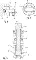
Figuren 1A und 1B zur Verdeutlichung des Ausblasens von Sperrluft aus der Spannvorrichtung und zur Erläuterung einer Abfrage der Entspann-Stellung mit einer Drossel (Meldung: Werkstück kann entnommen werden), - Figur 5
- eine weitere Querschnittsansicht durch die Spannvorrichtung aus den
Figuren 1A und 1B zur Verdeutlichung einer pneumatischen Abfrageeinrichtung, - Figur 6
- eine vergrößerte Detailansicht aus
Figur 2 zur Verdeutlichung des axialen Spiels der Spannbuchse als Voraussetzung für eine Niederzugsbewegung, - Figur 7
- eine vergrößerte Detailansicht in axialer Richtung auf dem eingerasteten Spannbolzen des Bajonettverschlusses,
- Figur 8
- eine Querschnittsansicht zur Verdeutlichung des Bajonettverschlusses für den Zuganker,
- Figur 9
- eine Abwandlung des Ausführungsbeispiels gemäß den
Figuren 1A bis 8 mit einer zusätzlichen Feder zur Eigensicherung, - Figur 10
- eine Abwandlung mit einer konischen Auflauffläche an der Spannbuchse zur radialen Aufweitung der Spannbuchse,
- Figur 11
- eine Abwandlung mit einem elastischen Ring zur Erleichterung des Einfügens des Gewindes,
- Figur 12
- eine Abwandlung mit einem Luftpolster zur Erleichterung des Einfügens des Gewindes, sowie
- Figur 13A
- eine Querschnittsansicht durch ein weiteres Ausführungsbeispiel entlang der Schnittlinie F-F in
Figur 13C , wobei der Bajonettverschluss eine Verdrehsicherung und eine Drehwinkelbegrenzung aufweist, - Figur 13B
- eine Schnittansicht entlang der Schnittlinie G-G in
Figur 13C , sowie - Figur 13C
- eine Querschnittsansicht des Ausführungsbeispiels gemäß den
Figuren 13A und 13B . - Die
Figuren 1A bis 8 zeigen verschiedene Ansichten einer erfindungsgemäßen Spannvorrichtung 1 zum Spannen eines Bauteils 2, wobei das Bauteil 2 nur inFigur 2 schematisch dargestellt ist und ansonsten zur Wahrung der Übersichtlichkeit weggelassen ist. Das Bauteil 2 weist zum Eingriff durch die Spannvorrichtung 1 eine Sackbohrung 3 mit einer Innenwand 4 auf, die mit einem Innengewinde 5 versehen ist, um einen formschlüssigen Eingriff zu ermöglichen, wie noch detailliert beschrieben wird. - Die Spannvorrichtung 1 weist ein Gehäuse 6 auf, das oben durch einen Gehäusedeckel 7 und unten durch einen Gehäuseboden 8 verschlossen ist. Der Ringspalt zwischen dem Gehäuseboden 8 und dem Gehäuse 6 ist hierbei durch eine Dichtung 9 abgedichtet.
- In der Spannvorrichtung 1 ist ein Zuganker 10 axial verschiebbar angeordnet, wobei der Zuganker 10 von einem ebenfalls axial verschiebbaren Kolben 11 verschoben werden kann, wie ebenfalls noch detailliert beschrieben wird. Der Ringspalt zwischen der äußeren Mantelfläche des Kolbens 11 und der Innenwand des Gehäuses 6 wird hierbei durch zwei Dichtungen 12, 13 abgedichtet.
- Der Kolben 11 weist eine axiale Durchgangsbohrung 14 auf, durch die das untere Ende des Zugankers 10 hindurchgeführt ist, wobei der Zuganker 10 in dem Kolben 11 durch einen lösbaren Bajonettverschluss verankert ist, wie noch detailliert beschrieben wird.
- In den Kolben 11 ist unten ein Kolbeneinsatz 15 eingesetzt, wobei sich am Boden des Kolbeneinsatzes 15 eine Feder 16 abstützt, die den Zuganker 10 axial nach oben drückt, damit sich der Bajonettverschluss des Zugankers 10 nicht versehentlich löst.
- Die Durchgangsbohrung 14 in dem Kolben 11 ist hierbei im Querschnitt als Langloch ausgeführt, wie aus
Figur 7 ersichtlich ist. Der Zuganker 10 weist an seinem unteren Ende eine hammerförmige seitliche Erweiterung 17 auf, die sich im verankerten Zustand des Bajonettverschlusses unten an Vorsprüngen 53 in dem Kolben 11 abstützt. In einer bestimmten Winkelstellung kann der Zuganker 10 also einfach in die Spannvorrichtung 1 eingeführt werden, da die als Langloch ausgebildete Durchgangsbohrung 14 dann ausreichend Platz bietet. Nach dem Einführen des Zugankers 10 wird der Zuganker 10 dann um 90° gedreht, woraufhin sich der Zuganker 10 mit seiner hammerförmigen Erweiterung 17 an dem Kolben 11 abstützt. - Es sind jedoch auch andere Varianten möglich, wie beispielsweise eine Befestigung z.B. über Schwenkkurve oder Rastbolzen.
- Die Feder 16 verhindert hierbei, dass sich der Zuganker 10 unabsichtlich dreht und dann aus der Spannvorrichtung 1 herausfallen könnte (Einrasten an dem Vorsprung 53).
- Darüber hinaus weist die Spannvorrichtung 1 im oberen Bereich ein Innenteil 18 auf, das den Zuganker 10 ringförmig umgibt und eine Durchgangsbohrung enthält, in der ein O-Ring 19 zur Vorzentrierung des Zugankers 10 angeordnet ist. Bei einem seitlichen Ausweichen des Zugankers 10 übt der O-Ring 19 nämlich eine nach innen gerichtete Gegenkraft aus, wodurch der Zuganker 10 in der Spannvorrichtung 1 zentriert wird.
- Das Innenteil 18 stützt sich hierbei über eine Druckfeder 20 an dem Gehäuse 6 ab. Die Druckfeder 20 drückt das Innenteil 18 also nach oben.
- Das freie Ende des Zugankers 10 ist von einer Spannbuchse 21 umgeben, wobei die Spannbuchse 21 beim Spannen des Bauteils 2 in die Sackbohrung 3 eingeführt wird und dann eine formschlüssige Verbindung herstellt. Hierzu weist die Spannbuchse 21 an ihrer äußeren Mantelfläche ein Außengewinde auf, das an das Innengewinde 5 der Sackbohrung 3 angepasst ist.
- Das freie Ende des Zugankers 10 weist eine äußere Mantelfläche auf, die sich zum Ende des Zugankers 10 hin konisch (alternativ sind auch Pyramidenflächen möglich) erweitert. Entsprechend weist auch die Spannbuchse 21 eine konische Innenwand auf, die sich zum freien Ende hin konisch erweitert. Ein Zurückziehen des Zugankers 10 in die Spannvorrichtung 1 hinein führt also aufgrund der aufeinander gleitenden konischen Flächen des Zugankers 10 einerseits und der Spannbuchse 21 andererseits dazu, dass sich die Spannbuchse 21 radial aufweitet. Das Außengewinde der Spannbuchse 21 greift dann in das entsprechend angepasste Innengewinde 5 der Sackbohrung 3 ein und stellt dadurch eine formschlüssige Verbindung her.
- Weiterhin ist zu erwähnen, dass die Spannbuchse 21 außen von einem ringförmigen Abstreifer 22 umgeben ist. Der Abstreifer 22 verhindert, dass Schmutz in die Spannvorrichtung 1 eindringen kann.
-
Figur 2 zeigt eine Querschnittsansicht der Spannvorrichtung 1 mit einem Hydraulikanschluss 23 zum Spannen des Zugankers 10. Der Hydraulikanschluss 23 ist über Ölkanäle 24, 25 mit einem Druckraum 26 verbunden, wobei der in dem Druckraum 26 wirkende Hydraulikdruck von oben auf den Kolben 11 drückt und den Kolben 11 ggf. nach unten drückt. Der Kolben 11 nimmt dann den Zuganker 10 entsprechend nach unten mit. Weiterhin ist hierbei zu erwähnen, dass der Ölkanal 25 an seiner Oberseite durch eine Stopfen 27 verschlossen ist. -
Figur 3 zeigt eine andere Querschnittsansicht der Spannvorrichtung aus denFiguren 1A und 1B mit einem Hydraulikanschluss 28 zum Entspannen der Spannvorrichtung 1. Der Hydraulikanschluss 28 ist über Ölkanäle 29, 30 mit einem Druckraum 31 verbunden, wobei der in dem Druckraum 31 herrschende Öldruck von unten auf den Kolben 11 wirkt und den Kolben 11 dadurch nach oben drückt. Hierbei ist zu erwähnen, dass der Ölkanal 30 an seiner Oberseite ebenfalls durch einen Stopfen 32 verschlossen ist. -
Figur 4 zeigt eine weitere Querschnittsansicht der Spannvorrichtung 1 mit einem weiteren Pneumatikanschluss 33 für eine Sperrlufteinrichtung und eine Abfrage der Entspannstellung des Kolbens (11). Der Pneumatikanschluss 33 ist über Druckluftkanäle 34, 35, 36, 48 mit einem Druckraum 37 in dem Gehäusedeckel 7 verbunden, von wo die Druckluft durch Ausblasöffnungen nach oben ausgeblasen werden kann, um den Auflagebereich der Spannvorrichtung 1 sauber zu halten. Hierbei ist zu erwähnen, dass der Druckluftkanal 34 außen durch einen Stopfen 38 verschlossen ist. - Eine Drossel 49 sorgt hierbei für eine Druckdifferenz. Im entspannten Zustand ist der Kolben 11 in seiner oberen Stellung und der Druckluftkanal 48 (Sperrluftkanal) verschlossen, d.h. es entsteht ein Druckunterschied zwischen gespannter- und entspannter Stellung.
-
Figur 5 zeigt noch eine weitere Querschnittsansicht der Spannvorrichtung 1 mit einem weiteren Pneumatikanschluss 39 für eine pneumatisch arbeitende Abfrageeinrichtung. - Der Pneumatikanschluss 39 der Abfrageeinrichtung mündet zum einen über einen Druckluftkanal 40 in den Zylinder, in dem der Kolben 11 axial verschiebbar ist. Auf diese Weise kann die Stellung des Kolbens 11 von der Abfrageeinrichtung abgefragt werden, da sich die Druckverhältnisse an dem Pneumatikanschluss 39 ändern, wenn der Kolben 11 die Mündungsöffnung des Druckluftkanals 40 freigibt.
- Zum anderen mündet der Pneumatikanschluss 39 der Abfrageeinrichtung aber auch über Druckluftkanäle 41, 42 in eine Auflagenkontrollbohrung 43, die im gespannten Zustand von dem Bauteil 2 verschlossen wird, wodurch sich die Druckverhältnisse an dem Pneumatikanschluss 39 ändern, was messtechnisch erfasst werden kann und dadurch eine Auflagenkontrolle ermöglicht.
- Im Folgenden wird nun die Funktionsweise der erfindungsgemäßen Spannvorrichtung 1 beschrieben.
- Hierbei wird davon ausgegangen, dass der Zuganker 10 bereits in der Spannvorrichtung 1 montiert und mittels des Bajonettverschlusses verankert ist. Die Feder 16 drückt den Zuganker 10 dann nach oben gegen den Kolben 11 und verhindert dadurch, dass sich der Bajonettverschluss beispielsweise bei Vibrationen oder Erschütterungen löst, was im schlimmsten Fall zu einem Herausfallen des Zugankers 10 führen könnte (Einrasten an dem Vorsprung 53).
- Die Spannvorrichtung 1 wird dann zunächst entspannt, indem über den Hydraulikanschluss 28 Öl zugeführt wird, die dann in dem Druckraum 31 von unten auf den Kolben 11 wirkt und den Kolben zusammen mit dem Zuganker 10 nach oben drückt. Während dieses Entspannens der Spannvorrichtung ist der Hydraulikanschluss 23 drucklos.
- Anschließend kann dann das Bauteil 2 so aufgesetzt werden, dass das freie Ende des Zugankers 10 mit der Spannbuchse 21 in die Sackbohrung 3 eingeführt wird.
- Hierbei ist zu erwähnen, dass die Spannbuchse 21 im entspannten Zustand einen Außendurchmesser aufweist, der kleiner ist als der Innendurchmesser der Innenwand 4 der Sackbohrung 3. Dies ist wichtig, damit der Zuganker 10 mit der Spannbuchse 21 im entspannten Zustand in die Sackbohrung 3 eingeführt werden kann.
- Nach dem Aufsetzen des Bauteils 2 auf die Spannvorrichtung 1 verschließt das Bauteil 2 die Auflagenkontrollbohrung 43 an der Oberseite der Spannvorrichtung 1, was an dem Pneumatikanschluss 39 messbar ist.
- Daraufhin wird die Spannvorrichtung 1 dann gespannt. Hierzu wird zunächst der Hydraulikanschluss 28 drucklos gemacht. Darüber hinaus wird der Hydraulikanschluss 23 angesteuert, so dass der Öldruck in dem Druckraum 26 den Kolben 11 zusammen mit dem Zuganker 10 nach unten zieht. Bei dieser Abwärtsbewegung des Zugankers 10 gleiten die konischen Flächen des Zugankers 10 und der Spannbuchse 21 aufeinander, was zu einer radialen Aufweitung der Spannbuchse 21 führt. Bei dieser radialen Aufweitung der Spannbuchse 21 greift das Außengewinde in der Mantelfläche der Spannbuchse 21 dann in das Innengewinde 5 in der Innenwand 4 der Sackbohrung 3 ein und stellt damit eine formschlüssige Verbindung zwischen der Spannbuchse 21 und dem Bauteil 2 her.
- Bei einer weiteren Abwärtsbewegung des Zugankers 10 führt das nun formschlüssig gespannte Bauteil 2 dann eine Niederzugsbewegung aus, um das Bauteil 2 fest an die Auflagefläche der Spannvorrichtung 1 zu ziehen. Hierbei ist zu erwähnen, dass die Spannbuchse 21 mit ihrer Unterseite auf dem Innenteil 18 aufliegt. Ein weiteres Herunterziehen des Zugankers 10 führt also zu einer entsprechenden Abwärtsbewegung der Spannbuchse 21 und damit auch des Innenteils 18, das sich an der Druckfeder 20 abstützt. Die Niederzugsbewegung muss also die Gegenkraft der Druckfeder 20 überwinden.
- Die Abfrageeinrichtung kann dann durch Abfrage der Druckverhältnisse an dem Pneumatikanschluss 39 ermitteln, ob das Bauteil 2 fest auf die Auflagefläche der Spannvorrichtung 1 gezogen ist, woraufhin der Spannvorgang dann beendet ist.
- Aus
Figur 6 ist ersichtlich, dass das Innenteil 18 und damit auch die Spannbuchse 21 in der Spannvorrichtung 1 mit einem axialen Spiel a gelagert ist, um nach dem Spannen des Bauteils 2 die Niederzugsbewegung zu ermöglichen. -
Figur 9 zeigt eine Abwandlung des vorstehend beschriebenen Ausführungsbeispiels, wobei dieses Ausführungsbeispiel weitgehend mit dem vorstehend beschriebenen Ausführungsbeispiel übereinstimmt, so dass zur Vermeidung von Wiederholungen auf die vorstehende Beschreibung Bezug genommen wird, wobei für entsprechende Einzelheiten dieselben Bezugszeichen verwendet werden. - Eine Besonderheit dieses Ausführungsbeispiels besteht darin, dass die Spannvorrichtung 1 eine sogenannte Eigensicherung aufweist. Dies bedeutet, dass das Bauteil 2 auch bei einem Druckausfall gespannt bleibt. Hierzu ist eine zusätzliche Feder 44 vorgesehen, die den Kolben 11 und damit auch den Zuganker 10 nach unten in die Spannstellung zieht.
- Schließlich zeigt
Figur 10 eine weitere Abwandlung, die ebenfalls weitgehend mit den vorstehend beschriebenen Ausführungsbeispielen übereinstimmt, so dass zur Vermeidung von Wiederholungen auf die vorstehende Beschreibung verwiesen wird, wobei für entsprechende Einzelheiten dieselben Bezugszeichen verwendet werden. - Eine Besonderheit dieses Ausführungsbeispiels besteht darin, dass die Spannbuchse 21 an ihrer Unterseite einen radial abstehenden Kragen 45 aufweist sowie eine konische Auflauffläche 46, die auf einer konischen Auflauffläche 47 der Spannvorrichtung gleiten kann. Bei der Niederzugsbewegung gleiten also die konischen Auflaufflächen 46, 47 aufeinander, so dass der radial abstehende Kragen 45 entgegen der radial gerichteten Gegenkraft der Druckfeder 20 nach außen ausweicht, was die Niederzugsbewegung erlaubt.
- Die
Figuren 11 und 12 zeigen Abwandlungen, die weitgehend mit den vorstehend beschriebenen Ausführungsbeispielen übereinstimmen, so dass zur Vermeidung von Wiederholungen auf die vorstehende Beschreibung verwiesen wird, wobei für entsprechende Einzelheiten dieselben Bezugszeichen verwendet werden. - Die Besonderheit von
Figur 11 besteht darin, dass die Spannbuchse 21 unten auf einem elastischen Ring 50 aufliegt, wodurch das Einfügen des Gewindes der Spannbuchse 21 erleichtert wird. - Die Besonderheit von
Figur 12 besteht darin, dass die Spannbuchse 21 unten auf einem Luftpolster 51 aufschwimmt, wodurch ebenfalls das Einfügen des Gewindes der Spannbuchse 21 erleichtert wird. - Die
Figuren 13A-13C zeigen verschiedene Schnittansichten eines weiteren Ausführungsbeispiels, das weitgehend mit den vorstehend beschriebenen Ausführungsbeispielen übereinstimmt, sodass zur Vermeidung von Wiederholungen auf die vorstehende Beschreibung verwiesen wird, wobei für entsprechende Einzelheiten dieselben Bezugszeichen verwendet werden. - Eine Besonderheit dieses Ausführungsbeispiels besteht darin, dass der Bajonettverschluss zwischen der hammerförmigen Erweiterung 17 des Zugankers 10 einerseits und dem Kolben 11 andererseits eine Drehwinkelbegrenzung aufweist, die aus zwei Stiften 54 besteht, die in entsprechende Bohrungen in dem Kolben 11 eingesteckt sind. Bei einer Drehung des Zugankers 10 um seine Längsachse stößt die hammerförmige Erweiterung 17 des Zugankers 10 dann an die Stifte 54 an, wodurch der Drehwinkel des Zugankers 10 begrenzt wird.
- Eine weitere Besonderheit dieses Ausführungsbeispiels besteht darin, dass der Bajonettverschluss eine Verdrehsicherung (Lösesicherung) aufweist, die ein unbeabsichtigtes Lösen des Bajonettverschlusses verhindert. Die Verdrehsicherung besteht im Wesentlichen aus einem weiteren Stift 55, der ebenfalls in eine entsprechende Bohrung in dem Kolben 11 eingesteckt ist. Der Stift 55 verhindert hierbei, dass sich der Zuganker 10 in eine Stellung dreht, die es erlaubt, den Zuganker 10 aus dem Kolben 11 herauszuziehen. Zum Lösen des Bajonettverschlusses muss hierbei also zunächst der Stift 55 entfernt werden. Anschließend kann dann der Zuganker 10 so gedreht werden, dass sich der Bajonettverschluss lösen lässt.
-
- 1
- Spannvorrichtung
- 2
- Bauteil
- 3
- Sackbohrung
- 4
- Innenwand der Sackbohrung
- 5
- Innengewinde der Sackbohrung
- 6
- Gehäuse der Spannvorrichtung
- 7
- Gehäusedeckel
- 8
- Gehäuseboden
- 9
- Dichtung zwischen Gehäuseboden und Gehäuse
- 10
- Zuganker
- 11
- Kolben
- 12
- Dichtung zwischen Kolben und Gehäuse
- 13
- Dichtung zwischen Kolben und Gehäuse
- 14
- Durchgangsbohrung im Kolben
- 15
- Kolbeneinsatz
- 16
- Feder zur Vorspannung des Zugankers
- 17
- Hammerförmige Erweiterung des Zugankers
- 18
- Innenteil
- 19
- O-Ring zur Vorzentrierung des Zugankers
- 20
- Druckfeder zum Vorspannen der Spannbuchse entgegen der Niederzugsbewegung
- 21
- Spannbuchse
- 22
- Abstreifer
- 23
- Hydraulikanschluss zum Spannen des Zugankers
- 24
- Ölkanal zum Spannen des Zugankers
- 25
- Ölkanal zum Spannen des Zugankers
- 26
- Druckraum zum Spannen des Zugankers
- 27
- Stopfen
- 28
- Hydraulikanschluss zum Entspannen des Zugankers
- 29
- Ölkanal zum Entspannen des Zugankers
- 30
- Ölkanal zum Entspannen des Zugankers
- 31
- Druckraum zum Entspannen des Zugankers
- 32
- Stopfen
- 33
- Pneumatikanschluss für Sperrlufteinrichtung
- 34
- Druckluftkanal der Sperrlufteinrichtung
- 35
- Druckluftkanal der Sperrlufteinrichtung
- 36
- Druckluftkanal der Sperrlufteinrichtung
- 37
- Druckraum der Sperrlufteinrichtung
- 38
- Stopfen
- 39
- Pneumatikanschluss der Abfrageeinrichtung
- 40
- Druckluftkanal der Abfrageeinrichtung (Kolbenstellungskontrolle)
- 41
- Druckluftkanal der Abfrageeinrichtung
- 42
- Druckluftkanal der Abfrageeinrichtung
- 43
- Auflagenkontrollbohrung
- 44
- Feder für Eigensicherung bei Druckausfall
- 45
- Kragen der Spannbuchse
- 46
- Auflauffläche der Spannbuchse
- 47
- Stationäre Auflauffläche
- 48
- Druckluftkanal Abfrage Entspann-Stellung
- 49
- Drossel/Drosselbohrung
- 50
- Elastischer Ring für Höhenausgleich
- 51
- Bohrung zur Erzeugung des Luftpolsters
- 52
- Druckluftkanal für Druckdifferenzmessung
- 53
- Vorsprung für Bajonettverschluss (Hammer des Zugankers)
- 54
- Stifte der Drehwinkelbegrenzung des Bajonettverschlusses
- 55
- Stift der Verdrehsicherung (Lösesicherung)
- a
- Axiales Spiel der Spannbuchse und des Innenteils
Claims (15)
- Spannvorrichtung (1) zum mechanischen Spannen eines Bauteils (2), insbesondere eines zu spannenden Werkstücks, mita) einem axial verschiebbaren Zuganker (10) zum Spannen des Bauteils (2),b) einem axial verschiebbaren Kolben (11) zum Verschieben des Zugankers (10),gekennzeichnet durchc) einen Bajonettverschluss zur lösbaren mechanischen Verankerung des Zugankers (10) in dem Kolben (11).
- Spannvorrichtung (1) nach Anspruch 1, gekennzeichnet durch eine Spannbuchse (21) zum Einspannen in einer Bohrung (3) des Bauteils (2),a) wobei die Spannbuchse (21) in einem entspannten Zustand radial zusammengezogen ist, so dass die Spannbuchse (21) in die Bohrung (3) eingeführt und aus der Bohrung (3) heraus gezogen werden kann,b) wohingegen die Spannbuchse (21) in einem gespannten Zustand radial aufgeweitet ist, so dass die Mantelfläche der Spannbuchse (21) eine mechanische Verbindung mit der Innenwand der Bohrung (3) bildet,c) wobei die mechanische Verbindung zwischen der Mantelfläche der Spannbuchse (21) und der Innenwand der Bohrung (3) formschlüssig ist,d) wobei ein Außengewinde in der Mantelfläche der Spannbuchse (21) eingebracht ist, um in ein Innengewinde (5) in der Innenwand (4) der Bohrung (3) einzugreifen und dadurch die formschlüssige Verbindung herzustellen.
- Spannvorrichtung (1) nach Anspruch 2,
dadurch gekennzeichnet,a) dass das Außengewinde der Spannbuchse (21) und das Innengewinde (5) der Bohrung (3) dieselbe Gewindesteigung aufweisen, und/oderb) dass das Außengewinde der Spannbuchse (21) im radial zusammengezogenen Zustand einen kleineren Gewindedurchmesser aufweist als das Innengewinde (5) der Bohrung (3), und/oderc) dass das Außengewinde der Spannbuchse (21) im radial aufgeweiteten Zustand den gleichen Gewindedurchmesser aufweist wie das Innengewinde (5) der Bohrung (3), und/oderd) dass im radial zusammengezogenen Zustand der Spannbuchse (21) der Außendurchmesser des Außengewindes der Spannbuchse (21) kleiner ist als der Kerndurchmesser des Innengewindes (5) der Bohrung (3). - Spannvorrichtung (1) nach einem der Ansprüche 2 bis 3,
dadurch gekennzeichnet,a) dass die Spannbuchse (21) über den Umfang der Spannbuchse (21) verteilt mehrere Segmente aufweist,b) dass die benachbarten Segmente jeweils durch einen axial verlaufenden Schlitz voneinander getrennt sind, undc) dass die einzelnen Schlitze vom freien Ende der Spannbuchse (21) ausgehen und sich zumindest über einen Teil der axialen Länge der Spannbuchse (21) erstrecken. - Spannvorrichtung (1) nach einem der Ansprüche 2 bis 4,
dadurch gekennzeichnet,a) dass die Spannbuchse (21) zentrisch eine axiale Durchgangsbohrung für einen Zuganker (10) aufweist, undb) dass sich die Durchgangsbohrung zum freien Ende der Spannbuchse (21) hin radial erweitert, insbesondere konisch, oderc) dass die Durchgangsbohrung zum freien Ende der Spannbuchse (21) hin pyramidenförmig in mehrere Fasen übergeht. - Spannvorrichtung (1) nach einem der Ansprüche 2 bis 5,
dadurch gekennzeichnet,a) dass der Zuganker (10) axial durch die Spannbuchse (21) verläuft und an seinem freien Ende eine konische oder schrägflächige Aufweitung aufweist, so dass der Zuganker (10) beim Zurückziehen des Zugankers (10) die Spannbuchse (21) radial aufweitet, und/oderb) dass der Zuganker(10) der axial durch die Spannbuchse (21) verläuft und an seinem freien Ende eine Aufweitung in Form mehrerer Fasen, insbesondere in Pyramidenform aufweist, so dass der Zuganker (10) beim Zurückziehen des Zugankers die Spannbuchse (21) radial aufweitet, und/oderc) dass im radial zusammengezogenen Zustand der Spannbuchse (21) der Außendurchmesser des Außengewindes der Spannbuchse (21) gleich dem Gewindedurchmesser des Innengewindes (5) ist, jedoch durch die Segmentierung im entspannten Zustand kleiner als der Kerndurchmesser (4) des Innengewindes (5) der Bohrung ist, und/oderd) dass im radial zusammengezogenen Zustand der Spannbuchse (21) die einzelnen Segmente auf einem Luftpolster (51) schwimmen und sich so das Einfügen des Gewindes erleichtert, und/odere) dass im radial zusammengezogenen Zustand der Spannbuchse (21) die einzelnen Segmente auf einem elastischen Ring (50) aufliegen und sich so das Einfügen des Gewindes erleichtert. - Spannvorrichtung (1) nach einem der vorhergehenden Ansprüche, dadurch gekennzeichnet,a) dass der Zuganker (10) durch den Bajonettverschluss auswechselbar ist und zwar ohne Öffnung der Fluidleitungen zum Antrieb des Kolbens (11), und/oderb) dass der Zuganker (10) an seinem unteren Ende eine hammerförmige seitlich Erweiterung (17) aufweist, und/oderc) dass der Kolben (11) zur Durchführung des Zugankers (10) eine Axialbohrung (14) aufweist, die im Querschnitt ein Langloch ist, so dass die hammerförmige Erweiterung (17) des Zugankers (10) in einer bestimmten Winkelstellung des Zugankers (10) durch die Axialbohrung (14) durchgeführt werden kann und ansonsten eine formschlüssige Verankerung des Zugankers (10) in dem Kolben (11) bewirkt, und/oderd) dass der Zuganker (10) durch eine erste Feder (16) gegen den Kolben (11) vorgespannt wird, um ein Herausfallen des Zugankers (10) zu vermeiden, und/odere) dass der Bajonettverschluss eine Drehwinkelbegrenzung (54) aufweist, um den Drehwinkel des Zugankers (10) zu begrenzen, und/oderf) dass die Drehwinkelbegrenzung (54) in beiden Drehrichtungen jeweils einen Drehwinkelanschlag (54) aufweist, und/oderg) dass der Drehwinkelanschlag (54) jeweils aus einem Stift (54) besteht.
- Spannvorrichtung (1) nach einem der vorhergehenden Ansprüche, dadurch gekennzeichnet,a) dass der Bajonettverschluss eine Verdrehsicherung (55) aufweist zur Verhinderung einer unbeabsichtigten Lösung des Bajonettverschlusses, und/oderb) dass die Verdrehsicherung (55) einen Drehwinkelanschlag (55) aufweist, der eine Verdrehung des Zugankers in eine Lösestellung verhindert, und/oderc) dass der Drehwinkelanschlag (55) einen Stift (55) aufweist.
- Spannvorrichtung (1) nach einem der vorhergehenden Ansprüche, gekennzeichnet durcha) einen ersten Druckraum (26) zur hydraulischen oder pneumatischen Druckbeaufschlagung des Kolbens (11) zum Spannen des Zugankers (10), und/oderb) einen zweiten Druckraum (31) zur hydraulischen oder pneumatischen Druckbeaufschlagung des Kolbens (11) zum Entspannen des Zugankers (10), und/oderc) eine zweite Feder (44), die den Kolben (11) in eine Spannstellung vorspannt, so dass das Bauteil (2) auch ohne eine Druckbeaufschlagung gehalten wird.
- Spannvorrichtung (1) nach einem der vorhergehenden Ansprüche, gekennzeichnet durch eine Abfrageeinrichtung zum Abfragen des Zustands der Spannvorrichtung (1), insbesondere zur Erkennung der folgenden Zustände:a) Bruch des Zugankers (10),b) Bruch der Spannbuchse (21),c) Auflage oder Abwesenheit eines Bauteils (2) auf der Spannvorrichtung (1),d) Stellung des Zugankers (10) und/oder des Kolbens (11)in der Entspannstellung (48).e) Bohrung im Werkstück zu groß (40).
- Spannvorrichtung (1) nach einem der vorhergehenden Ansprüche, gekennzeichnet durch eine Sperrlufteinrichtung zum Ausblasen von Sperrluft im Bereich einer Auflage um das freie Ende des Zugankers (10) herum.
- Spannvorrichtung (1) nach einem der Ansprüche 2 bis 11,
dadurch gekennzeichnet,a) dass die Spannvorrichtung (1) zum Vorzentrieren des Zugankers (10) ein elastisches Zentrierungselement (19) aufweist, insbesondere in Form eines den Zuganker (10) umgebenden O-Rings (19), und/oderb) dass Zentrierungselement (19) die Spannbuchse (21) und den Zuganker (10) ringförmig umgibt, oderc) dass das Zentrierungselement (19) den Zuganker (10) ringförmig umgibt und unterhalb der Spannbuchse (21) angeordnet ist. - Spannvorrichtung (1) nach einem der Ansprüche 2 bis 12,
dadurch gekennzeichnet,a) dass die Spannbuchse (21) in der Spannvorrichtung (1) mit einem axialen Spiel (a) gelagert ist, damit die Spannbuchse (21) eine axiale Niederzugsbewegung ausführen kann, und/oderb) dass eine dritte Feder (20) vorgesehen ist zum Vorspannen der Spannbuchse (21) entgegen der Niederzugsbewegung. - Spannvorrichtung (1) nach Anspruch 13,
dadurch gekennzeichnet,a) dass die Spannbuchse (21) unten einen radial abstehenden Kragen (45) aufweist und die dritte Feder (20) den radial abstehenden Kragen (45) außen umgibt und radial nach innen drückt, oderb) dass die dritte Feder (20) unter der Spannbuchse (21) angeordnet ist und die Spannbuchse (21) axial nach oben drückt. - Spannvorrichtung (1) nach einem der Ansprüche 7 bis 14, dadurch gekennzeichnet,a) dass die Spannbuchse (21) an ihrer Unterseite eine konische Auflauffläche (46) aufweist, die sich nach oben hin konisch verjüngt, undb) dass die Spannbuchse (21) mit ihrer konischen Auflauffläche (46) auf einer in der Spannvorrichtung (1) fixierten konischen Auflauffläche (47) aufliegt, undc) dass die Spannbuchse (21) bei einem Spannvorgang sowohl radial aufgeweitet wird als auch aufgrund der aufeinander gleitenden Auflaufflächen (46, 47) axial niedergezogen wird.
Applications Claiming Priority (3)
| Application Number | Priority Date | Filing Date | Title |
|---|---|---|---|
| DE102014004104.2A DE102014004104B4 (de) | 2014-03-21 | 2014-03-21 | Radial aufzuweitende Spannbuchse mit Außengewinde zum Spannen eines Bauteils mit Innengewinde |
| EP15712528.7A EP3119555B1 (de) | 2014-03-21 | 2015-03-18 | Spannvorrichtung mit spannbuchse |
| PCT/EP2015/000597 WO2015139838A1 (de) | 2014-03-21 | 2015-03-18 | Spannbuchse und spannvorrichtung |
Related Parent Applications (2)
| Application Number | Title | Priority Date | Filing Date |
|---|---|---|---|
| EP15712528.7A Division EP3119555B1 (de) | 2014-03-21 | 2015-03-18 | Spannvorrichtung mit spannbuchse |
| EP15712528.7A Division-Into EP3119555B1 (de) | 2014-03-21 | 2015-03-18 | Spannvorrichtung mit spannbuchse |
Publications (2)
| Publication Number | Publication Date |
|---|---|
| EP3330041A1 EP3330041A1 (de) | 2018-06-06 |
| EP3330041B1 true EP3330041B1 (de) | 2018-12-19 |
Family
ID=52745859
Family Applications (2)
| Application Number | Title | Priority Date | Filing Date |
|---|---|---|---|
| EP17207353.8A Active EP3330041B1 (de) | 2014-03-21 | 2015-03-18 | Spannvorrichtung mit spannbuchse |
| EP15712528.7A Active EP3119555B1 (de) | 2014-03-21 | 2015-03-18 | Spannvorrichtung mit spannbuchse |
Family Applications After (1)
| Application Number | Title | Priority Date | Filing Date |
|---|---|---|---|
| EP15712528.7A Active EP3119555B1 (de) | 2014-03-21 | 2015-03-18 | Spannvorrichtung mit spannbuchse |
Country Status (7)
| Country | Link |
|---|---|
| US (1) | US10940542B2 (de) |
| EP (2) | EP3330041B1 (de) |
| JP (1) | JP2017512663A (de) |
| CN (2) | CN110421188B (de) |
| DE (1) | DE102014004104B4 (de) |
| ES (1) | ES2708835T3 (de) |
| WO (1) | WO2015139838A1 (de) |
Cited By (1)
| Publication number | Priority date | Publication date | Assignee | Title |
|---|---|---|---|---|
| DE102019120427A1 (de) * | 2019-07-29 | 2021-02-04 | Ludwig Ehrhardt Gmbh | Bohrungsspanner |
Families Citing this family (36)
| Publication number | Priority date | Publication date | Assignee | Title |
|---|---|---|---|---|
| JP6886158B2 (ja) * | 2017-01-25 | 2021-06-16 | 株式会社コスメック | クランプ装置 |
| CN107052847A (zh) * | 2017-04-24 | 2017-08-18 | 长沙博大机械零部件有限公司 | 一种内扩式端盖密封板拉紧夹具 |
| CN107378019B (zh) * | 2017-09-13 | 2019-05-07 | 湖南南方通用航空发动机有限公司 | 压气机轮盘的榫槽加工装置 |
| WO2019095248A1 (zh) * | 2017-11-17 | 2019-05-23 | 华亚工业塑胶太仓有限公司 | 一种便于安装和拆卸的夹具 |
| CN108115565B (zh) * | 2017-12-19 | 2024-07-12 | 浙江嘉益保温科技股份有限公司 | 自动抛光机中可控伸缩的夹紧夹具 |
| CN108772728B (zh) * | 2018-09-11 | 2019-01-01 | 遨博(江苏)机器人有限公司 | 可气检测量的金加工夹紧装置 |
| CN109262005B (zh) * | 2018-11-05 | 2019-12-03 | 台州凌智传动科技有限公司 | 电机壳车端面工装及其加工工艺 |
| CN109900639B (zh) * | 2019-04-17 | 2022-05-10 | 德玛克(长兴)自动化系统有限公司 | 一种塑料容器中间体检测用固定装置 |
| CN110153761B (zh) * | 2019-06-21 | 2024-04-16 | 珠海罗西尼表业有限公司 | 手表零件加工工装 |
| CN112474481A (zh) * | 2019-07-01 | 2021-03-12 | 云和县凯毅德电子设备厂 | 一种多功能轴承加工用除尘装置 |
| CN110360224B (zh) * | 2019-07-17 | 2021-04-02 | 烟台大丰轴瓦有限责任公司 | 轴瓦加工工艺 |
| CN111157450B (zh) * | 2020-02-18 | 2024-12-24 | 中国人民解放军陆军装甲兵学院 | 一种内孔涂层结合强度测试装置及测试方法 |
| CN111673106B (zh) * | 2020-07-15 | 2024-05-03 | 重庆新登奇机电技术有限公司 | 一种电机切削用定位工装 |
| CN111805209B (zh) * | 2020-07-16 | 2021-12-28 | 鹤壁泛华汽车电器有限责任公司 | 一种汽车转向器导磁环注塑总成压装设备 |
| CN112222797B (zh) * | 2020-09-22 | 2024-12-20 | 成都银河动力有限公司 | 一种装配活塞销孔衬套装置及方法 |
| CN112575935B (zh) * | 2020-12-12 | 2022-02-01 | 深圳新艺华建筑装饰工程有限公司 | 一种节能型玻璃建筑幕墙 |
| CN112594410B (zh) * | 2020-12-16 | 2022-07-29 | 武昌船舶重工集团有限公司 | 一种上装阀杆式球阀 |
| CN112621663B (zh) * | 2020-12-30 | 2025-05-09 | 陕西金禹科技发展有限公司 | 一种挠性阀门装配工具 |
| DE102021113993A1 (de) | 2021-05-31 | 2022-05-12 | Schaeffler Technologies AG & Co. KG | Hydraulische Spannvorrichtung |
| DE102021117229B4 (de) * | 2021-07-05 | 2024-12-05 | Lang Technik Gmbh | Spannvorrichtung und Verfahren zur Handhabung eines Werkstücks |
| CN114005708B (zh) * | 2021-08-24 | 2024-11-15 | 法泰电器(江苏)股份有限公司 | 一种塑壳断路器机构弹簧装配装置 |
| CN114310370A (zh) * | 2021-11-19 | 2022-04-12 | 江阴市力隆液压机械有限公司 | 高精密珩磨管张力内芯轴加工工装 |
| CN114083012B (zh) * | 2021-12-22 | 2025-05-09 | 上海交运汽车动力系统有限公司 | 一种夹持设备 |
| CN116442137B (zh) * | 2022-01-06 | 2026-02-24 | 苏州微创关节医疗科技有限公司 | 工装夹具 |
| CN115498560B (zh) * | 2022-08-28 | 2024-05-03 | 贵州电网有限责任公司 | 一种应用于垂直升降式剥皮器的夹持装置 |
| CN115411657B (zh) * | 2022-08-28 | 2024-05-07 | 贵州电网有限责任公司 | 一种垂直升降式配网引流线夹带电安装装置 |
| CN116123180B (zh) * | 2022-11-25 | 2026-04-21 | 河南恒创精密制造股份有限公司 | 用于液压系统的密封连接件 |
| CN116728314B (zh) * | 2023-07-14 | 2025-06-17 | 深圳市天一智能科技有限公司 | 一种定位涨紧夹持气动装置 |
| US12233494B1 (en) * | 2023-08-22 | 2025-02-25 | GM Global Technology Operations LLC | Tool for assembling a main assembly using a single stroke |
| CN117182682B (zh) * | 2023-09-22 | 2024-03-29 | 河北冠都机械有限公司 | 一种铝铸件生产用加工装置 |
| CN117365320B (zh) * | 2023-10-13 | 2024-08-16 | 西南石油大学 | 一种纯机械式可锁定钻杆旋转工具 |
| KR20250128583A (ko) * | 2024-02-21 | 2025-08-28 | 주식회사 유니테스트 | 유틸리티 공급용 오토 커플러 |
| CN118269038A (zh) * | 2024-03-19 | 2024-07-02 | 华能罗源发电有限责任公司 | 一种大型电动机辅助拆卸工具 |
| CN118544105B (zh) * | 2024-07-30 | 2024-10-15 | 赣州嘉荣智能科技有限公司 | 一种传感器内衬套压配机器人 |
| CN118616764B (zh) * | 2024-08-13 | 2024-11-19 | 兴化市祥和制药机械有限公司 | 一种机械加工用管件钻孔设备 |
| CN120244663B (zh) * | 2025-05-30 | 2025-08-05 | 江苏恒源精密机械制造有限公司 | 一种汽车转向节主销孔高精度加工设备 |
Family Cites Families (23)
| Publication number | Priority date | Publication date | Assignee | Title |
|---|---|---|---|---|
| US2360054A (en) | 1943-10-16 | 1944-10-10 | Aircraft Screw Prod Co | Insert expanding tool |
| US2497633A (en) * | 1947-04-08 | 1950-02-14 | Shapiro Jack | Internally applied expanding gripping tool |
| US2594429A (en) | 1949-10-17 | 1952-04-29 | Century Geophysical Corp | Pipe-lifting device |
| DE2502561A1 (de) | 1975-01-23 | 1976-07-29 | Foell Remswerk | Spanndorn fuer rohre |
| DE4020981A1 (de) * | 1990-07-02 | 1992-01-16 | Pasquale Dipl Ing Cianci | Spannvorrichtung |
| DE4039227A1 (de) * | 1990-12-08 | 1992-07-02 | Sauter Kg Feinmechanik | Verfahren und vorrichtung zum wechseln der werkzeugscheibe eines werkzeugrevolvers |
| US5026223A (en) * | 1990-12-20 | 1991-06-25 | Gte Valenite Corporation | Bayonet tool locking device |
| US5647627A (en) | 1995-11-09 | 1997-07-15 | Baessler; David J. | Pipe puller |
| JP3550010B2 (ja) * | 1997-12-24 | 2004-08-04 | 株式会社コスメック | クランプ装置 |
| JP4260488B2 (ja) * | 2003-01-07 | 2009-04-30 | 株式会社コスメック | 調心駆動機構およびその機構を備えた位置決め装置 |
| DE10318316A1 (de) | 2003-04-19 | 2004-10-28 | Narex Česká Lípa a.s. | Spannvorrichtung zum Festspannen eines Gegenstandes gegen einen Anschlag |
| DE102004025256A1 (de) * | 2004-05-17 | 2005-12-08 | Hainbuch Gmbh Spannende Technik | Werckstückspannsystem |
| CN101142053A (zh) * | 2005-03-18 | 2008-03-12 | 克斯美库股份有限公司 | 螺纹啮合型夹紧装置、夹紧系统及流体压力致动器 |
| DE102007039032A1 (de) * | 2007-08-17 | 2009-02-19 | Pasquale Cianci | Niederzugspanner |
| WO2009096150A1 (ja) | 2008-01-28 | 2009-08-06 | Pascal Engineering Corporation | ワークパレット位置決め固定装置 |
| JP4297511B1 (ja) * | 2008-02-15 | 2009-07-15 | パスカルエンジニアリング株式会社 | クランプ装置 |
| JP4302174B1 (ja) * | 2008-02-15 | 2009-07-22 | パスカルエンジニアリング株式会社 | クランプ装置 |
| JP5346542B2 (ja) * | 2008-04-24 | 2013-11-20 | パスカルエンジニアリング株式会社 | クランプ装置 |
| JP5557630B2 (ja) | 2010-07-13 | 2014-07-23 | パスカルエンジニアリング株式会社 | クランプ装置 |
| JP5827602B2 (ja) * | 2012-06-28 | 2015-12-02 | 株式会社コスメック | クランプ装置 |
| DE102013003053B4 (de) * | 2013-02-20 | 2014-12-24 | Gebr. Heller Maschinenfabrik Gmbh | Spannvorrichtung sowie Verfahren zum Spannen von Werkstücken mit axial verschiebbarer Spannschraube in axial verschiebbarem Stößel |
| DE202013103278U1 (de) | 2013-07-22 | 2013-08-08 | Narr Beteiligungs Gmbh | Spannvorrichtung |
| CA2843304A1 (en) | 2013-07-22 | 2015-01-22 | Narr Beteiligungs Gmbh | Clamping device |
-
2014
- 2014-03-21 DE DE102014004104.2A patent/DE102014004104B4/de not_active Expired - Fee Related
-
2015
- 2015-03-18 EP EP17207353.8A patent/EP3330041B1/de active Active
- 2015-03-18 CN CN201910525346.6A patent/CN110421188B/zh active Active
- 2015-03-18 ES ES17207353T patent/ES2708835T3/es active Active
- 2015-03-18 CN CN201580021117.0A patent/CN106457418B/zh active Active
- 2015-03-18 WO PCT/EP2015/000597 patent/WO2015139838A1/de not_active Ceased
- 2015-03-18 EP EP15712528.7A patent/EP3119555B1/de active Active
- 2015-03-18 JP JP2016558105A patent/JP2017512663A/ja active Pending
- 2015-03-18 US US15/127,561 patent/US10940542B2/en active Active
Non-Patent Citations (1)
| Title |
|---|
| None * |
Cited By (4)
| Publication number | Priority date | Publication date | Assignee | Title |
|---|---|---|---|---|
| DE102019120427A1 (de) * | 2019-07-29 | 2021-02-04 | Ludwig Ehrhardt Gmbh | Bohrungsspanner |
| WO2021018532A1 (de) | 2019-07-29 | 2021-02-04 | Ludwig Ehrhardt Gmbh | Bohrungsspanner |
| DE102019120427B4 (de) | 2019-07-29 | 2024-05-02 | Ludwig Ehrhardt Gmbh | Bohrungsspanner mit Rückstelleinrichtung |
| US12233520B2 (en) | 2019-07-29 | 2025-02-25 | Ludwig Ehrhardt Gmbh | Bore clamp |
Also Published As
| Publication number | Publication date |
|---|---|
| CN106457418A (zh) | 2017-02-22 |
| WO2015139838A1 (de) | 2015-09-24 |
| CN106457418B (zh) | 2019-06-04 |
| CN110421188A (zh) | 2019-11-08 |
| EP3119555B1 (de) | 2018-01-31 |
| EP3119555A1 (de) | 2017-01-25 |
| CN110421188B (zh) | 2021-09-14 |
| US20170136551A1 (en) | 2017-05-18 |
| DE102014004104A1 (de) | 2015-09-24 |
| US10940542B2 (en) | 2021-03-09 |
| DE102014004104B4 (de) | 2018-04-26 |
| EP3330041A1 (de) | 2018-06-06 |
| ES2708835T3 (es) | 2019-04-11 |
| JP2017512663A (ja) | 2017-05-25 |
Similar Documents
| Publication | Publication Date | Title |
|---|---|---|
| EP3330041B1 (de) | Spannvorrichtung mit spannbuchse | |
| DE102014019712B4 (de) | Spannvorrichtung mit einem Zuganker, verbunden mit einem Kolben durch einen Bajonettverschluss | |
| EP4003649B1 (de) | Bohrungsspanner | |
| EP3084379B1 (de) | Kraftsensor für handbetriebene oder pneumatische pressen | |
| EP2898223B1 (de) | Kolbeneinheit eines arbeitszylinders | |
| EP3655682B1 (de) | Dichtungsring | |
| DE2517613B2 (de) | Bohrlochwerkzeug sowie Verfahren zum Befestigen und Lösen eines Bohrlochwerkzeugs auf bzw. von einem Bohrgestänge | |
| EP3874173B1 (de) | Vorgespannte wälzlagerung | |
| DE202012009001U1 (de) | Arbeitszylinder | |
| DE102016205904A1 (de) | Spannvorrichtung zum Vorspannen einer Anordnung mit einer Gewindestange | |
| DE112019000578B4 (de) | Fluidleckage-erfassungsvorrichtung und hin- und herbewegende fluiddruckvorrichtung | |
| DE4401622C2 (de) | Befestigungsvorrichtung für ein Montageglied einer Mutter-Schraube-Verbindung | |
| DE60007980T2 (de) | Holmverriegelung durch reibung | |
| DE10122249B4 (de) | Verfahren und Vorrichtung zum Bearbeiten von ringartigen Werkstücken | |
| DE102017000671B4 (de) | Drehfutter und Werkzeugmaschine | |
| DE2554948C2 (de) | Spannpresse zum Spannen und Verankern von Spanndrähten o.dgl. | |
| WO2017220758A1 (de) | Verschlusselement zum verschliessen und abdichten innendruckbeanspruchter bohrungen | |
| DE102011005052A1 (de) | Spannsystem zur lösbaren Verbindung zweier vorzugsweise rotationssymetrischer Teile | |
| EP4059646A1 (de) | Verfahren zur herstellung einer modularen spannvorrichtung für rotationssymmetrische körper und damit gefertigte spannvorrichtung | |
| DE102012018592B3 (de) | Rheologisches Messgerät mit einer Antriebswelle und einem daran anbringbaren Messteilschaft | |
| DE102011104403B4 (de) | Verfahren zur Kalibration einer Reibungskupplung und Formwerkzeug dafür | |
| EP3738700A1 (de) | Hydraulisch spannbarer werkzeug-/werkstückhalter | |
| EP3086001B1 (de) | Verschlussschraube | |
| DE112014000059T5 (de) | Konfiguration zum Verschließen einer Öldruckkreis-Öffnung | |
| DE20310503U1 (de) | Meßpunkt-Bolzen |
Legal Events
| Date | Code | Title | Description |
|---|---|---|---|
| PUAI | Public reference made under article 153(3) epc to a published international application that has entered the european phase |
Free format text: ORIGINAL CODE: 0009012 |
|
| STAA | Information on the status of an ep patent application or granted ep patent |
Free format text: STATUS: THE APPLICATION HAS BEEN PUBLISHED |
|
| STAA | Information on the status of an ep patent application or granted ep patent |
Free format text: STATUS: REQUEST FOR EXAMINATION WAS MADE |
|
| AC | Divisional application: reference to earlier application |
Ref document number: 3119555 Country of ref document: EP Kind code of ref document: P |
|
| AK | Designated contracting states |
Kind code of ref document: A1 Designated state(s): AL AT BE BG CH CY CZ DE DK EE ES FI FR GB GR HR HU IE IS IT LI LT LU LV MC MK MT NL NO PL PT RO RS SE SI SK SM TR |
|
| 17P | Request for examination filed |
Effective date: 20180508 |
|
| RBV | Designated contracting states (corrected) |
Designated state(s): AL AT BE BG CH CY CZ DE DK EE ES FI FR GB GR HR HU IE IS IT LI LT LU LV MC MK MT NL NO PL PT RO RS SE SI SK SM TR |
|
| RIC1 | Information provided on ipc code assigned before grant |
Ipc: B23B 31/40 20060101ALI20180713BHEP Ipc: B25B 27/02 20060101ALI20180713BHEP Ipc: B23Q 3/06 20060101ALI20180713BHEP Ipc: B23Q 1/00 20060101AFI20180713BHEP |
|
| GRAP | Despatch of communication of intention to grant a patent |
Free format text: ORIGINAL CODE: EPIDOSNIGR1 |
|
| STAA | Information on the status of an ep patent application or granted ep patent |
Free format text: STATUS: GRANT OF PATENT IS INTENDED |
|
| INTG | Intention to grant announced |
Effective date: 20180906 |
|
| GRAS | Grant fee paid |
Free format text: ORIGINAL CODE: EPIDOSNIGR3 |
|
| GRAA | (expected) grant |
Free format text: ORIGINAL CODE: 0009210 |
|
| STAA | Information on the status of an ep patent application or granted ep patent |
Free format text: STATUS: THE PATENT HAS BEEN GRANTED |
|
| AC | Divisional application: reference to earlier application |
Ref document number: 3119555 Country of ref document: EP Kind code of ref document: P |
|
| AK | Designated contracting states |
Kind code of ref document: B1 Designated state(s): AL AT BE BG CH CY CZ DE DK EE ES FI FR GB GR HR HU IE IS IT LI LT LU LV MC MK MT NL NO PL PT RO RS SE SI SK SM TR |
|
| REG | Reference to a national code |
Ref country code: GB Ref legal event code: FG4D Free format text: NOT ENGLISH |
|
| REG | Reference to a national code |
Ref country code: CH Ref legal event code: EP |
|
| REG | Reference to a national code |
Ref country code: IE Ref legal event code: FG4D Free format text: LANGUAGE OF EP DOCUMENT: GERMAN |
|
| REG | Reference to a national code |
Ref country code: DE Ref legal event code: R096 Ref document number: 502015007360 Country of ref document: DE |
|
| REG | Reference to a national code |
Ref country code: AT Ref legal event code: REF Ref document number: 1078167 Country of ref document: AT Kind code of ref document: T Effective date: 20190115 |
|
| REG | Reference to a national code |
Ref country code: CH Ref legal event code: NV Representative=s name: KASCHE AND PARTNER AG, CH |
|
| REG | Reference to a national code |
Ref country code: ES Ref legal event code: FG2A Ref document number: 2708835 Country of ref document: ES Kind code of ref document: T3 Effective date: 20190411 |
|
| REG | Reference to a national code |
Ref country code: NL Ref legal event code: MP Effective date: 20181219 |
|
| PG25 | Lapsed in a contracting state [announced via postgrant information from national office to epo] |
Ref country code: LV Free format text: LAPSE BECAUSE OF FAILURE TO SUBMIT A TRANSLATION OF THE DESCRIPTION OR TO PAY THE FEE WITHIN THE PRESCRIBED TIME-LIMIT Effective date: 20181219 Ref country code: HR Free format text: LAPSE BECAUSE OF FAILURE TO SUBMIT A TRANSLATION OF THE DESCRIPTION OR TO PAY THE FEE WITHIN THE PRESCRIBED TIME-LIMIT Effective date: 20181219 Ref country code: NO Free format text: LAPSE BECAUSE OF FAILURE TO SUBMIT A TRANSLATION OF THE DESCRIPTION OR TO PAY THE FEE WITHIN THE PRESCRIBED TIME-LIMIT Effective date: 20190319 Ref country code: BG Free format text: LAPSE BECAUSE OF FAILURE TO SUBMIT A TRANSLATION OF THE DESCRIPTION OR TO PAY THE FEE WITHIN THE PRESCRIBED TIME-LIMIT Effective date: 20190319 Ref country code: LT Free format text: LAPSE BECAUSE OF FAILURE TO SUBMIT A TRANSLATION OF THE DESCRIPTION OR TO PAY THE FEE WITHIN THE PRESCRIBED TIME-LIMIT Effective date: 20181219 Ref country code: FI Free format text: LAPSE BECAUSE OF FAILURE TO SUBMIT A TRANSLATION OF THE DESCRIPTION OR TO PAY THE FEE WITHIN THE PRESCRIBED TIME-LIMIT Effective date: 20181219 |
|
| REG | Reference to a national code |
Ref country code: LT Ref legal event code: MG4D |
|
| PG25 | Lapsed in a contracting state [announced via postgrant information from national office to epo] |
Ref country code: SE Free format text: LAPSE BECAUSE OF FAILURE TO SUBMIT A TRANSLATION OF THE DESCRIPTION OR TO PAY THE FEE WITHIN THE PRESCRIBED TIME-LIMIT Effective date: 20181219 Ref country code: RS Free format text: LAPSE BECAUSE OF FAILURE TO SUBMIT A TRANSLATION OF THE DESCRIPTION OR TO PAY THE FEE WITHIN THE PRESCRIBED TIME-LIMIT Effective date: 20181219 Ref country code: AL Free format text: LAPSE BECAUSE OF FAILURE TO SUBMIT A TRANSLATION OF THE DESCRIPTION OR TO PAY THE FEE WITHIN THE PRESCRIBED TIME-LIMIT Effective date: 20181219 Ref country code: GR Free format text: LAPSE BECAUSE OF FAILURE TO SUBMIT A TRANSLATION OF THE DESCRIPTION OR TO PAY THE FEE WITHIN THE PRESCRIBED TIME-LIMIT Effective date: 20190320 |
|
| PG25 | Lapsed in a contracting state [announced via postgrant information from national office to epo] |
Ref country code: NL Free format text: LAPSE BECAUSE OF FAILURE TO SUBMIT A TRANSLATION OF THE DESCRIPTION OR TO PAY THE FEE WITHIN THE PRESCRIBED TIME-LIMIT Effective date: 20181219 |
|
| PG25 | Lapsed in a contracting state [announced via postgrant information from national office to epo] |
Ref country code: PT Free format text: LAPSE BECAUSE OF FAILURE TO SUBMIT A TRANSLATION OF THE DESCRIPTION OR TO PAY THE FEE WITHIN THE PRESCRIBED TIME-LIMIT Effective date: 20190419 Ref country code: CZ Free format text: LAPSE BECAUSE OF FAILURE TO SUBMIT A TRANSLATION OF THE DESCRIPTION OR TO PAY THE FEE WITHIN THE PRESCRIBED TIME-LIMIT Effective date: 20181219 Ref country code: PL Free format text: LAPSE BECAUSE OF FAILURE TO SUBMIT A TRANSLATION OF THE DESCRIPTION OR TO PAY THE FEE WITHIN THE PRESCRIBED TIME-LIMIT Effective date: 20181219 |
|
| PG25 | Lapsed in a contracting state [announced via postgrant information from national office to epo] |
Ref country code: EE Free format text: LAPSE BECAUSE OF FAILURE TO SUBMIT A TRANSLATION OF THE DESCRIPTION OR TO PAY THE FEE WITHIN THE PRESCRIBED TIME-LIMIT Effective date: 20181219 Ref country code: IS Free format text: LAPSE BECAUSE OF FAILURE TO SUBMIT A TRANSLATION OF THE DESCRIPTION OR TO PAY THE FEE WITHIN THE PRESCRIBED TIME-LIMIT Effective date: 20190419 Ref country code: SM Free format text: LAPSE BECAUSE OF FAILURE TO SUBMIT A TRANSLATION OF THE DESCRIPTION OR TO PAY THE FEE WITHIN THE PRESCRIBED TIME-LIMIT Effective date: 20181219 Ref country code: RO Free format text: LAPSE BECAUSE OF FAILURE TO SUBMIT A TRANSLATION OF THE DESCRIPTION OR TO PAY THE FEE WITHIN THE PRESCRIBED TIME-LIMIT Effective date: 20181219 Ref country code: SK Free format text: LAPSE BECAUSE OF FAILURE TO SUBMIT A TRANSLATION OF THE DESCRIPTION OR TO PAY THE FEE WITHIN THE PRESCRIBED TIME-LIMIT Effective date: 20181219 |
|
| REG | Reference to a national code |
Ref country code: DE Ref legal event code: R097 Ref document number: 502015007360 Country of ref document: DE |
|
| PLBE | No opposition filed within time limit |
Free format text: ORIGINAL CODE: 0009261 |
|
| STAA | Information on the status of an ep patent application or granted ep patent |
Free format text: STATUS: NO OPPOSITION FILED WITHIN TIME LIMIT |
|
| PG25 | Lapsed in a contracting state [announced via postgrant information from national office to epo] |
Ref country code: MC Free format text: LAPSE BECAUSE OF FAILURE TO SUBMIT A TRANSLATION OF THE DESCRIPTION OR TO PAY THE FEE WITHIN THE PRESCRIBED TIME-LIMIT Effective date: 20181219 Ref country code: DK Free format text: LAPSE BECAUSE OF FAILURE TO SUBMIT A TRANSLATION OF THE DESCRIPTION OR TO PAY THE FEE WITHIN THE PRESCRIBED TIME-LIMIT Effective date: 20181219 |
|
| 26N | No opposition filed |
Effective date: 20190920 |
|
| PG25 | Lapsed in a contracting state [announced via postgrant information from national office to epo] |
Ref country code: LU Free format text: LAPSE BECAUSE OF NON-PAYMENT OF DUE FEES Effective date: 20190318 |
|
| REG | Reference to a national code |
Ref country code: BE Ref legal event code: MM Effective date: 20190331 |
|
| PG25 | Lapsed in a contracting state [announced via postgrant information from national office to epo] |
Ref country code: IE Free format text: LAPSE BECAUSE OF NON-PAYMENT OF DUE FEES Effective date: 20190318 |
|
| PG25 | Lapsed in a contracting state [announced via postgrant information from national office to epo] |
Ref country code: BE Free format text: LAPSE BECAUSE OF NON-PAYMENT OF DUE FEES Effective date: 20190331 |
|
| PG25 | Lapsed in a contracting state [announced via postgrant information from national office to epo] |
Ref country code: TR Free format text: LAPSE BECAUSE OF FAILURE TO SUBMIT A TRANSLATION OF THE DESCRIPTION OR TO PAY THE FEE WITHIN THE PRESCRIBED TIME-LIMIT Effective date: 20181219 |
|
| PG25 | Lapsed in a contracting state [announced via postgrant information from national office to epo] |
Ref country code: MT Free format text: LAPSE BECAUSE OF FAILURE TO SUBMIT A TRANSLATION OF THE DESCRIPTION OR TO PAY THE FEE WITHIN THE PRESCRIBED TIME-LIMIT Effective date: 20181219 |
|
| PG25 | Lapsed in a contracting state [announced via postgrant information from national office to epo] |
Ref country code: CY Free format text: LAPSE BECAUSE OF FAILURE TO SUBMIT A TRANSLATION OF THE DESCRIPTION OR TO PAY THE FEE WITHIN THE PRESCRIBED TIME-LIMIT Effective date: 20181219 |
|
| PG25 | Lapsed in a contracting state [announced via postgrant information from national office to epo] |
Ref country code: HU Free format text: LAPSE BECAUSE OF FAILURE TO SUBMIT A TRANSLATION OF THE DESCRIPTION OR TO PAY THE FEE WITHIN THE PRESCRIBED TIME-LIMIT; INVALID AB INITIO Effective date: 20150318 |
|
| PG25 | Lapsed in a contracting state [announced via postgrant information from national office to epo] |
Ref country code: SI Free format text: LAPSE BECAUSE OF FAILURE TO SUBMIT A TRANSLATION OF THE DESCRIPTION OR TO PAY THE FEE WITHIN THE PRESCRIBED TIME-LIMIT Effective date: 20181219 |
|
| PG25 | Lapsed in a contracting state [announced via postgrant information from national office to epo] |
Ref country code: MK Free format text: LAPSE BECAUSE OF FAILURE TO SUBMIT A TRANSLATION OF THE DESCRIPTION OR TO PAY THE FEE WITHIN THE PRESCRIBED TIME-LIMIT Effective date: 20181219 |
|
| P01 | Opt-out of the competence of the unified patent court (upc) registered |
Effective date: 20230424 |
|
| PGFP | Annual fee paid to national office [announced via postgrant information from national office to epo] |
Ref country code: ES Payment date: 20250416 Year of fee payment: 11 |
|
| PGFP | Annual fee paid to national office [announced via postgrant information from national office to epo] |
Ref country code: IT Payment date: 20250331 Year of fee payment: 11 |
|
| PGFP | Annual fee paid to national office [announced via postgrant information from national office to epo] |
Ref country code: CH Payment date: 20250401 Year of fee payment: 11 |
|
| REG | Reference to a national code |
Ref country code: CH Ref legal event code: R17 Free format text: ST27 STATUS EVENT CODE: U-0-0-R10-R17 (AS PROVIDED BY THE NATIONAL OFFICE) Effective date: 20251212 |
|
| REG | Reference to a national code |
Ref country code: CH Ref legal event code: U11 Free format text: ST27 STATUS EVENT CODE: U-0-0-U10-U11 (AS PROVIDED BY THE NATIONAL OFFICE) Effective date: 20260401 |
|
| PGFP | Annual fee paid to national office [announced via postgrant information from national office to epo] |
Ref country code: GB Payment date: 20260324 Year of fee payment: 12 |
|
| PGFP | Annual fee paid to national office [announced via postgrant information from national office to epo] |
Ref country code: DE Payment date: 20260325 Year of fee payment: 12 |
|
| PGFP | Annual fee paid to national office [announced via postgrant information from national office to epo] |
Ref country code: AT Payment date: 20260319 Year of fee payment: 12 |
|
| PGFP | Annual fee paid to national office [announced via postgrant information from national office to epo] |
Ref country code: FR Payment date: 20260324 Year of fee payment: 12 |