EP3338938A1 - Method for modifying a shroud and blade - Google Patents
Method for modifying a shroud and blade Download PDFInfo
- Publication number
- EP3338938A1 EP3338938A1 EP17207975.8A EP17207975A EP3338938A1 EP 3338938 A1 EP3338938 A1 EP 3338938A1 EP 17207975 A EP17207975 A EP 17207975A EP 3338938 A1 EP3338938 A1 EP 3338938A1
- Authority
- EP
- European Patent Office
- Prior art keywords
- cut
- shroud
- end edge
- airfoil
- radius
- Prior art date
- Legal status (The legal status is an assumption and is not a legal conclusion. Google has not performed a legal analysis and makes no representation as to the accuracy of the status listed.)
- Granted
Links
Images


Classifications
-
- F—MECHANICAL ENGINEERING; LIGHTING; HEATING; WEAPONS; BLASTING
- F01—MACHINES OR ENGINES IN GENERAL; ENGINE PLANTS IN GENERAL; STEAM ENGINES
- F01D—NON-POSITIVE DISPLACEMENT MACHINES OR ENGINES, e.g. STEAM TURBINES
- F01D5/00—Blades; Blade-carrying members; Heating, heat-insulating, cooling or antivibration means on the blades or the members
- F01D5/12—Blades
- F01D5/22—Blade-to-blade connections, e.g. for damping vibrations
- F01D5/225—Blade-to-blade connections, e.g. for damping vibrations by shrouding
-
- B—PERFORMING OPERATIONS; TRANSPORTING
- B23—MACHINE TOOLS; METAL-WORKING NOT OTHERWISE PROVIDED FOR
- B23P—METAL-WORKING NOT OTHERWISE PROVIDED FOR; COMBINED OPERATIONS; UNIVERSAL MACHINE TOOLS
- B23P6/00—Restoring or reconditioning objects
- B23P6/002—Repairing turbine components, e.g. moving or stationary blades, rotors
-
- F—MECHANICAL ENGINEERING; LIGHTING; HEATING; WEAPONS; BLASTING
- F01—MACHINES OR ENGINES IN GENERAL; ENGINE PLANTS IN GENERAL; STEAM ENGINES
- F01D—NON-POSITIVE DISPLACEMENT MACHINES OR ENGINES, e.g. STEAM TURBINES
- F01D5/00—Blades; Blade-carrying members; Heating, heat-insulating, cooling or antivibration means on the blades or the members
- F01D5/005—Repairing methods or devices
-
- F—MECHANICAL ENGINEERING; LIGHTING; HEATING; WEAPONS; BLASTING
- F05—INDEXING SCHEMES RELATING TO ENGINES OR PUMPS IN VARIOUS SUBCLASSES OF CLASSES F01-F04
- F05D—INDEXING SCHEME FOR ASPECTS RELATING TO NON-POSITIVE-DISPLACEMENT MACHINES OR ENGINES, GAS-TURBINES OR JET-PROPULSION PLANTS
- F05D2230/00—Manufacture
- F05D2230/10—Manufacture by removing material
-
- F—MECHANICAL ENGINEERING; LIGHTING; HEATING; WEAPONS; BLASTING
- F05—INDEXING SCHEMES RELATING TO ENGINES OR PUMPS IN VARIOUS SUBCLASSES OF CLASSES F01-F04
- F05D—INDEXING SCHEME FOR ASPECTS RELATING TO NON-POSITIVE-DISPLACEMENT MACHINES OR ENGINES, GAS-TURBINES OR JET-PROPULSION PLANTS
- F05D2230/00—Manufacture
- F05D2230/80—Repairing, retrofitting or upgrading methods
-
- F—MECHANICAL ENGINEERING; LIGHTING; HEATING; WEAPONS; BLASTING
- F05—INDEXING SCHEMES RELATING TO ENGINES OR PUMPS IN VARIOUS SUBCLASSES OF CLASSES F01-F04
- F05D—INDEXING SCHEME FOR ASPECTS RELATING TO NON-POSITIVE-DISPLACEMENT MACHINES OR ENGINES, GAS-TURBINES OR JET-PROPULSION PLANTS
- F05D2240/00—Components
- F05D2240/10—Stators
- F05D2240/11—Shroud seal segments
-
- F—MECHANICAL ENGINEERING; LIGHTING; HEATING; WEAPONS; BLASTING
- F05—INDEXING SCHEMES RELATING TO ENGINES OR PUMPS IN VARIOUS SUBCLASSES OF CLASSES F01-F04
- F05D—INDEXING SCHEME FOR ASPECTS RELATING TO NON-POSITIVE-DISPLACEMENT MACHINES OR ENGINES, GAS-TURBINES OR JET-PROPULSION PLANTS
- F05D2240/00—Components
- F05D2240/20—Rotors
- F05D2240/30—Characteristics of rotor blades, i.e. of any element transforming dynamic fluid energy to or from rotational energy and being attached to a rotor
- F05D2240/307—Characteristics of rotor blades, i.e. of any element transforming dynamic fluid energy to or from rotational energy and being attached to a rotor related to the tip of a rotor blade
-
- F—MECHANICAL ENGINEERING; LIGHTING; HEATING; WEAPONS; BLASTING
- F05—INDEXING SCHEMES RELATING TO ENGINES OR PUMPS IN VARIOUS SUBCLASSES OF CLASSES F01-F04
- F05D—INDEXING SCHEME FOR ASPECTS RELATING TO NON-POSITIVE-DISPLACEMENT MACHINES OR ENGINES, GAS-TURBINES OR JET-PROPULSION PLANTS
- F05D2250/00—Geometry
- F05D2250/10—Two-dimensional
- F05D2250/19—Two-dimensional machined; miscellaneous
- F05D2250/192—Two-dimensional machined; miscellaneous bevelled
Definitions
- the subject matter disclosed herein relates to turbine engines. More particularly, the subject matter relates to modifying of turbine parts.
- a compressor provides pressurized air to one or more combustors wherein the air is mixed with fuel and burned to generate hot combustion gas. These gases flow downstream to a turbine that extracts energy therefrom to produce a mechanical energy output as well as power to drive the compressor.
- turbine parts such as blades or nozzles, may experience fatigue, due to extreme conditions within the turbine, including high temperatures and pressures caused by flow of hot gas.
- certain turbine parts such as blades located on a turbine rotor, may experience fatigue that requires servicing or replacement.
- repair process may further fatigue the local area.
- repair of some defect locations occurring due to wear and tear is not feasible. Replacement of these parts can be costly, especially if fatigue in selected areas occurs in several parts, such as blades on a rotor wheel.
- a method for modifying an airfoil shroud located at a tip of an airfoil has a first end edge, second end edge, leading edge and a trailing edge.
- a locating step locates a reference location in the first end edge.
- the reference location includes a portion of a fillet.
- a seal rail extends circumferentially along a radially outer surface of the airfoil shroud.
- the fillet extends along the radially outer surface and is positioned directly adjacent to the seal rail.
- a forming step forms a compound relief cut in the fillet without performing a weld process on the airfoil shroud to remove the reference location.
- the compound relief cut has a first cut having a first radius extending from the seal rail towards the first end edge, and a second cut having a second radius extending from an end of the first cut to the first end edge.
- the second radius is larger than the first radius. Modifying the airfoil shroud is complete following forming the compound relief cut.
- a blade includes an airfoil having an airfoil axis.
- a shroud is disposed at a tip of the airfoil, and the shroud has a first end edge, a second end edge, a leading edge and a trailing edge.
- a seal rail extends circumferentially along a radially outer surface of the shroud.
- a fillet extends along the radially outer surface of the shroud and is positioned directly adjacent to the seal rail.
- a compound relief cut is formed in the first end edge of the shroud.
- the compound relief cut has a first cut having a first radius extending away from the seal rail and towards the first end edge, and a second cut having a second radius extending away from an end of the first cut to the first end edge.
- the second radius is larger than the first radius.
- a turbine includes a rotor, and a blade coupled to the rotor.
- the blade includes an airfoil having an airfoil axis.
- a shroud is disposed at a tip of the airfoil, and the shroud has a first end edge, a second end edge, a leading edge and a trailing edge.
- a seal rail extends circumferentially along a radially outer surface of the shroud.
- a fillet extends along the radially outer surface of the shroud and is positioned directly adjacent to the seal rail.
- a compound relief cut is formed in the first end edge of the shroud.
- the compound relief cut has a first cut having a first radius extending away from the seal rail and towards the first end edge, and a second cut having a second radius extending away from an end of the first cut to the first end edge.
- the second radius is larger than the first radius.
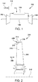
- FIG. 1 is a schematic diagram of an embodiment of a gas turbine system (or turbomachine) 100.
- the system 100 includes a compressor 102, a combustor 104, a turbine 106, a shaft (or rotor) 108 and a fuel nozzle 110.
- the system 100 may include a plurality of compressors 102, radially outerustors 104, turbines 106, shafts 108 and fuel nozzles 110.
- the compressor 102 and turbine 106 are coupled by the shaft 108.
- the shaft 108 may be a single shaft or a plurality of shaft segments coupled together to form shaft 108.
- the combustor 104 uses liquid and/or gas fuel, such as natural gas or a hydrogen rich synthetic gas, to run the turbine system.
- fuel nozzles 110 are in fluid communication with a fuel supply 112 and pressurized air from the compressor 102.
- the fuel nozzles 110 create an air-fuel mix, and discharge the air-fuel mix into the combustor 104, thereby causing a combustion that creates a hot pressurized exhaust gas.
- the combustor 104 directs the hot pressurized exhaust gas through a transition piece into a rotor and stator assembly, causing turbine 106 rotation as the gas exits nozzles where the gas is then directed to the turbine blades.
- the rotation of the blades coupled to the rotor in turbine 106 causes the shaft 108 to rotate, thereby compressing the air as it flows into the compressor 102.
- a relief cut is formed in a shroud of a blade (or nozzle) in the turbine.
- the shroud is positioned on a turbine blade.
- the relief cut is formed to modify the shroud and remove a defect or reference location in the airfoil shroud.
- the reference location is a flaw or defect, such as a crack, that has been identified on the shroud.
- the defect or reference location may be caused by fatigue from exposure to extreme heat and pressure during turbine operation.
- the relief cut is formed without welding the shroud, thus reducing incidence of additional fatigue that may be introduced to the shroud by a welding process.
- the relief cut provides a structurally sound repair to the airfoil shroud to enable reuse and reinstallation of the airfoil following forming of the relief cut. Accordingly, the repair process provides savings in time and costs when servicing the airfoil.
- downstream and upstream are terms that indicate a direction relative to the flow of working fluid through the turbine.
- downstream refers to a direction that generally corresponds to the direction of the flow of working fluid
- upstream generally refers to the direction that is opposite to the direction of flow of working fluid.
- leading edge and “trailing edge” indicate a position of a part relative to the flow of working fluid. Specifically, a leading edge of an airfoil encounters hot gas flow before a trailing edge of the airfoil.
- radial refers to movement or position perpendicular to an axis or center line of a reference part or assembly.
- first component resides closer to the axis than a second component, it may be stated herein that the first component is "radially inward” of the second component. If, on the other hand, the first component resides further from the axis than the second component, it can be stated herein that the first component is “radially outward” or “outboard” of the second component.
- axial refers to movement or position parallel to an axis. For example, the longitudinal centerline of shaft 108 defines an axial axis of the turbine system 100.
- circumferential refers to movement or position around an axis.
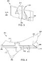
- FIG. 2 is a side view of a blade 200.
- FIG. 3 is a top view of the blade 200 shown in FIG. 3 .
- a plurality of blades 200 are coupled to a rotor wheel in a turbine, such as the turbine engine system 100.
- the blade 200 includes an airfoil 202.
- the airfoil 202 converts the energy of a hot gas flow 206 into tangential motion of the blade, which in turn rotates the rotor to which the blade is attached.
- a seal rail 204 is provided to prevent the passage of hot gas flow 206 through a gap between the blade tip and the inner surface of the surrounding stationary components (not shown).
- the seal rail 204 extends circumferentially from a surface of a radially outer side (or surface) 214 of a shroud 208 located at the bucket tip.
- the shroud 208 includes the radially outer side 214 and a radially inner side (or surface) 216.
- the seal rail 204 extends circumferentially around a blade row on the rotor, beyond the airfoil 202 sufficiently to line up with seal rails provided at the tip of adjacent blades, effectively blocking flow from bypassing the bucket row so that airflow must be directed to the working length of the blade 202.
- the blades and rotor rotate about rotor axis 212.
- an airfoil axis 210 extends generally perpendicularly to axis 212 and longitudinally through the airfoil 202.
- the shroud 208 is a flat plate supported towards its center by the airfoil 202, where the shroud 208 is subject to high temperatures and centrifugal loads during turbine operation. As a result, portions of the shroud 208 may experience fatigue over time, where embodiments of the modifying process described herein repair fatigue, such as defect, flaw or reference locations in the blade shroud.
- FIG. 4 illustrates a top view of a blade shroud 400 disposed at a tip of an airfoil as described above.
- the blade (or airfoil) shroud 400 has a leading edge 402, a trailing edge 404, a first end edge 406 and a second end edge 408 defining the shroud.
- a seal rail 412 extends along a radially outer side 414 of the shroud in a circumferential direction from the first end edge 406 to the second end edge 408.
- the first end edge 406 is configured to be placed adjacent the second end edge 408 of an adjacent shroud to provide a substantially continuous circumferential seal rail assembly in the turbine stage.
- the circumferential direction is defined as a path generally following the outer diameter of a circle (or tangent to the periphery of the circle), the origin of the circle would be an axial direction (going into and out of the page on which the circle is drawn), and a radial direction would be parallel to the page on which the circle is drawn and beginning at the origin and extending out in a straight line to any point on the circle.
- the circumferential seal rail assembly blocks hot gas flow (e.g., 206) from bypassing the blade row so that flow is directed along a working length of the blade's airfoil.
- the seal rail 412 has fillets 413 on each side extending along the radially outer surface 414 to provide support for the seal rail 412.
- the reference location 410 is a crack proximate to the fillet 413 of seal rail 412.
- a relief cut may be used to repair and remove the reference location 410, as described below. The relief cut may be formed without performing a weld process on the shroud.
- the shroud 400 may also incorporate a hard face coating (or layer) 415 in selected regions thereof.
- the hard face coating 415 may be a wear resistant material, such as flame sprayed chrome carbide (or any other suitable material).
- the hard face 415 is located on surfaces of the shroud that may come in contact with (or rub against) neighboring shroud portions. For example, a neighboring (or second) shroud (not shown) would have a second edge 408 that makes contact with the hard face layer 415 of the first shroud (shown).
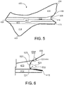
- FIG. 5 illustrates a top view of a blade shroud 400 disposed at a tip of an airfoil, according to an aspect of the present invention.
- the shroud 400 has a compound relief cut 520 formed in the end edge of the shroud.
- the relief cut 520 may extend through the hard face layer 415 located at the ends of fillet 413 and/or seal rail 412.
- the compound relief cut has two sections with each having a different radius of curvature, and this configuration reduces stress in the part and increases part operating lifetime.
- FIG. 6 illustrates an enlarged view of the relief cut region, as shown in FIG. 5 .
- the hard face layer 415 is located on the end of seal rail 412, and may be present on the end of fillet 413 before the compound relief cut is formed.
- the compound relief cut 520 is formed in a portion of the first end edge 406, and is comprised of a first cut 521 and a second cut 523, where the first cut is joined smoothly to the second cut.
- the first cut 521 begins at or in the seal rail 412 and extends away from the seal rail towards a distal end of the first end edge 406.
- the first cut 521 has a curved profile with a first radius 522.
- the second cut 523 begins at the end of the first cut 521, and extends away from the first cut to the first end edge 406.
- the second cut 523 also has a curved profile, but has a second radius 524.
- the second radius 524 is larger than the first radius 522.
- the first radius 522 may be about 0.100 inches to about 0.125 inches, and the second radius may be about 0.125 inches to about 0.200 inches.
- the term "about” is defined as giving the stated values a tolerance of 10%.
- the compound relief cut 520 is formed of two different radius cuts (or curves) being joined smoothly together. The end of the first cut 521 is the beginning of the second cut 523.
- the exterior angle 531 is the angle formed external to the part, and angle 531 is a reflex angle.
- a reflex angle is greater than 180 degrees but less than 360 degrees.
- the reflex angle 531 may be about 181 degrees to about 225 degrees, however, any suitable reflex angle may be used as desired in the specific application.
- An interior angle 530 is also formed between the end of the second cut 523 and the adjacent first end edge portion 406.
- the interior angle 530 is the angle formed inside the part, and interior angle 530 is an obtuse angle.
- An obtuse angle is less than 180 degrees but greater than 90 degrees.
- a summation of angle 530 and angle 531 equals 360 degrees.
- interior angle 530 may be about 135 degrees to about 179 degrees, however, any suitable obtuse angle may be used as desired in the specific application.
- the compound relief cut 520 may be formed partially into the hard face layer 415.
- FIG. 7 illustrates a schematic view of the compound relief cut 520.
- the first cut 521 extends for about 30 degrees of arc away from parallel with the seal rail 412. For example, beginning at the seal rail the first cut 521 begins and continues over an arc of about 30 degrees.
- the second cut 523 which begins at the end of the first cut, extends for an additional about 60 degrees to about 90 degrees of arc away from parallel with the seal rail.
- the compound relief cut 520 (which includes both the first and second cuts) extends for about 90 degrees to about 120 degrees of arc away from parallel with the seal rail. However, any suitable degree of arc swing could be used for both the first and second cuts.
- FIG. 8 illustrates a method 800 for modifying an airfoil shroud, according to an aspect of the present invention.
- the method 800 may include a locating step 810 that locates a reference location 410 in the first end edge 406 of the airfoil shroud.
- the reference location may include a portion of a fillet 413.
- the fillet 413 extends along the radially outer surface 414 and is positioned directly adjacent to the seal rail, which extends circumferentially along the radially outer surface 414 of the airfoil shroud.
- a forming step 820 forms a compound relief cut 520 in the fillet 413 without performing a weld process on the airfoil shroud to remove the reference location 410.
- the compound relief cut 520 may be formed with a grinder, drill bit, router or any other suitable abrasive or cutting tool.
- the compound relief cut 520 has a first cut 521 having a first radius 522 extending from the seal rail 412 towards the first end edge 406, and a second cut 523 having a second radius 524 extending from an end of the first cut 521 to the first end edge 406.
- the second radius 524 is larger than the first radius 522.
- the forming step may include cutting through the hard face layer to form the compound relief cut. Modifying the airfoil shroud is complete following forming the compound relief cut 520, and the airfoil shroud may be installed in a turbomachine following the formation of the relief cut in step 830.
Landscapes
- Engineering & Computer Science (AREA)
- Mechanical Engineering (AREA)
- General Engineering & Computer Science (AREA)
- Turbine Rotor Nozzle Sealing (AREA)
Abstract
Description
- The subject matter disclosed herein relates to turbine engines. More particularly, the subject matter relates to modifying of turbine parts.
- In a gas turbine, a compressor provides pressurized air to one or more combustors wherein the air is mixed with fuel and burned to generate hot combustion gas. These gases flow downstream to a turbine that extracts energy therefrom to produce a mechanical energy output as well as power to drive the compressor. Over time, turbine parts, such as blades or nozzles, may experience fatigue, due to extreme conditions within the turbine, including high temperatures and pressures caused by flow of hot gas. In particular, certain turbine parts, such as blades located on a turbine rotor, may experience fatigue that requires servicing or replacement.
- In cases where defect locations in fatigued areas utilize welding or other heat-based operations, the repair process may further fatigue the local area. Thus, repair of some defect locations occurring due to wear and tear is not feasible. Replacement of these parts can be costly, especially if fatigue in selected areas occurs in several parts, such as blades on a rotor wheel.
- According to one aspect, a method for modifying an airfoil shroud located at a tip of an airfoil is provided. The airfoil shroud has a first end edge, second end edge, leading edge and a trailing edge. A locating step locates a reference location in the first end edge. The reference location includes a portion of a fillet. A seal rail extends circumferentially along a radially outer surface of the airfoil shroud. The fillet extends along the radially outer surface and is positioned directly adjacent to the seal rail. A forming step forms a compound relief cut in the fillet without performing a weld process on the airfoil shroud to remove the reference location. The compound relief cut has a first cut having a first radius extending from the seal rail towards the first end edge, and a second cut having a second radius extending from an end of the first cut to the first end edge. The second radius is larger than the first radius. Modifying the airfoil shroud is complete following forming the compound relief cut.
- According to another aspect, a blade includes an airfoil having an airfoil axis. A shroud is disposed at a tip of the airfoil, and the shroud has a first end edge, a second end edge, a leading edge and a trailing edge. A seal rail extends circumferentially along a radially outer surface of the shroud. A fillet extends along the radially outer surface of the shroud and is positioned directly adjacent to the seal rail. A compound relief cut is formed in the first end edge of the shroud. The compound relief cut has a first cut having a first radius extending away from the seal rail and towards the first end edge, and a second cut having a second radius extending away from an end of the first cut to the first end edge. The second radius is larger than the first radius.
- According to yet another aspect, a turbine includes a rotor, and a blade coupled to the rotor. The blade includes an airfoil having an airfoil axis. A shroud is disposed at a tip of the airfoil, and the shroud has a first end edge, a second end edge, a leading edge and a trailing edge. A seal rail extends circumferentially along a radially outer surface of the shroud. A fillet extends along the radially outer surface of the shroud and is positioned directly adjacent to the seal rail. A compound relief cut is formed in the first end edge of the shroud. The compound relief cut has a first cut having a first radius extending away from the seal rail and towards the first end edge, and a second cut having a second radius extending away from an end of the first cut to the first end edge. The second radius is larger than the first radius.
- These and other advantages and features will become more apparent from the following description taken in conjunction with the drawings.
- The subject matter, which is regarded as the invention, is particularly pointed out and distinctly claimed in the claims at the conclusion of the specification. The foregoing and other features, and advantages of the invention are apparent from the following detailed description taken in conjunction with the accompanying drawings in which:
-
FIG. 1 illustrates a schematic diagram of an embodiment of a gas turbine system; -
FIG. 2 illustrates a side view of an embodiment of a blade having a shroud; -
FIG. 3 illustrates a top view of the blade ofFIG. 2 ; -
FIG. 4 illustrates a top view of an embodiment of a blade or airfoil shroud having a flaw; -
FIG. 5 illustrates a top view of the airfoil shroud shown inFIG. 4 with a relief cut to repair the flaw, according to an aspect of the present invention; -
FIG. 6 illustrates an enlarged and top view of the relief cut region shown inFIG. 5 , according to an aspect of the present invention; -
FIG. 7 illustrates a schematic view of the compound relief cut, according to an aspect of the present invention; and -
FIG. 8 illustrates a method for modifying an airfoil shroud, according to an aspect of the present invention. - The detailed description explains embodiments of the invention, together with advantages and features, by way of example with reference to the drawings.
-
FIG. 1 is a schematic diagram of an embodiment of a gas turbine system (or turbomachine) 100. Thesystem 100 includes acompressor 102, acombustor 104, aturbine 106, a shaft (or rotor) 108 and afuel nozzle 110. Thesystem 100 may include a plurality ofcompressors 102, radiallyouterustors 104,turbines 106,shafts 108 andfuel nozzles 110. - As depicted, the
compressor 102 andturbine 106 are coupled by theshaft 108. Theshaft 108 may be a single shaft or a plurality of shaft segments coupled together to formshaft 108. - In an aspect, the
combustor 104 uses liquid and/or gas fuel, such as natural gas or a hydrogen rich synthetic gas, to run the turbine system. For example,fuel nozzles 110 are in fluid communication with afuel supply 112 and pressurized air from thecompressor 102. Thefuel nozzles 110 create an air-fuel mix, and discharge the air-fuel mix into thecombustor 104, thereby causing a combustion that creates a hot pressurized exhaust gas. Thecombustor 104 directs the hot pressurized exhaust gas through a transition piece into a rotor and stator assembly, causingturbine 106 rotation as the gas exits nozzles where the gas is then directed to the turbine blades. The rotation of the blades coupled to the rotor inturbine 106 causes theshaft 108 to rotate, thereby compressing the air as it flows into thecompressor 102. - In embodiments, a relief cut is formed in a shroud of a blade (or nozzle) in the turbine. In an embodiment, the shroud is positioned on a turbine blade. The relief cut is formed to modify the shroud and remove a defect or reference location in the airfoil shroud. In an embodiment, the reference location is a flaw or defect, such as a crack, that has been identified on the shroud. The defect or reference location may be caused by fatigue from exposure to extreme heat and pressure during turbine operation. In an embodiment, the relief cut is formed without welding the shroud, thus reducing incidence of additional fatigue that may be introduced to the shroud by a welding process. In one embodiment, the relief cut provides a structurally sound repair to the airfoil shroud to enable reuse and reinstallation of the airfoil following forming of the relief cut. Accordingly, the repair process provides savings in time and costs when servicing the airfoil.
- As used herein, "downstream" and "upstream" are terms that indicate a direction relative to the flow of working fluid through the turbine. As such, the term "downstream" refers to a direction that generally corresponds to the direction of the flow of working fluid, and the term "upstream" generally refers to the direction that is opposite to the direction of flow of working fluid. In addition, the terms "leading edge" and "trailing edge" indicate a position of a part relative to the flow of working fluid. Specifically, a leading edge of an airfoil encounters hot gas flow before a trailing edge of the airfoil. The term "radial" refers to movement or position perpendicular to an axis or center line of a reference part or assembly. It may be useful to describe parts that are at differing radial positions with regard to an axis. In this case, if a first component resides closer to the axis than a second component, it may be stated herein that the first component is "radially inward" of the second component. If, on the other hand, the first component resides further from the axis than the second component, it can be stated herein that the first component is "radially outward" or "outboard" of the second component. The term "axial" refers to movement or position parallel to an axis. For example, the longitudinal centerline of
shaft 108 defines an axial axis of theturbine system 100. Finally, the term "circumferential" refers to movement or position around an axis. Although the following discussion primarily focuses on gas turbines, the concepts discussed are not limited to gas turbines and may apply to any suitable rotating machinery, including steam turbines. Accordingly, the discussion herein is directed to gas turbine embodiments, but may apply to steam turbines and other turbomachinery. -
FIG. 2 is a side view of ablade 200.FIG. 3 is a top view of theblade 200 shown inFIG. 3 . In embodiments, a plurality ofblades 200 are coupled to a rotor wheel in a turbine, such as theturbine engine system 100. Theblade 200 includes anairfoil 202. In an embodiment, theairfoil 202 converts the energy of ahot gas flow 206 into tangential motion of the blade, which in turn rotates the rotor to which the blade is attached. At the top of theairfoil 202, aseal rail 204 is provided to prevent the passage ofhot gas flow 206 through a gap between the blade tip and the inner surface of the surrounding stationary components (not shown). As depicted, theseal rail 204 extends circumferentially from a surface of a radially outer side (or surface) 214 of ashroud 208 located at the bucket tip. As depicted, theshroud 208 includes the radiallyouter side 214 and a radially inner side (or surface) 216. In an assembly of blades on a rotor, theseal rail 204 extends circumferentially around a blade row on the rotor, beyond theairfoil 202 sufficiently to line up with seal rails provided at the tip of adjacent blades, effectively blocking flow from bypassing the bucket row so that airflow must be directed to the working length of theblade 202. During operation, the blades and rotor rotate aboutrotor axis 212. In addition, anairfoil axis 210 extends generally perpendicularly toaxis 212 and longitudinally through theairfoil 202. - In embodiments, the
shroud 208 is a flat plate supported towards its center by theairfoil 202, where theshroud 208 is subject to high temperatures and centrifugal loads during turbine operation. As a result, portions of theshroud 208 may experience fatigue over time, where embodiments of the modifying process described herein repair fatigue, such as defect, flaw or reference locations in the blade shroud. -
FIG. 4 illustrates a top view of ablade shroud 400 disposed at a tip of an airfoil as described above. The blade (or airfoil)shroud 400 has aleading edge 402, a trailingedge 404, afirst end edge 406 and asecond end edge 408 defining the shroud. Aseal rail 412 extends along a radiallyouter side 414 of the shroud in a circumferential direction from thefirst end edge 406 to thesecond end edge 408. In a blade row assembly for a rotor, thefirst end edge 406 is configured to be placed adjacent thesecond end edge 408 of an adjacent shroud to provide a substantially continuous circumferential seal rail assembly in the turbine stage. The circumferential direction is defined as a path generally following the outer diameter of a circle (or tangent to the periphery of the circle), the origin of the circle would be an axial direction (going into and out of the page on which the circle is drawn), and a radial direction would be parallel to the page on which the circle is drawn and beginning at the origin and extending out in a straight line to any point on the circle. The circumferential seal rail assembly blocks hot gas flow (e.g., 206) from bypassing the blade row so that flow is directed along a working length of the blade's airfoil. - The
seal rail 412 hasfillets 413 on each side extending along the radiallyouter surface 414 to provide support for theseal rail 412. During operation of the turbine, fatigue caused by high pressures and temperatures can cause formation of a flaw, defect orreference location 410 in theshroud 400. In an embodiment, thereference location 410 is a crack proximate to thefillet 413 ofseal rail 412. In cases such as these, where thereference location 410 is in or proximate to a structural region, such as one or more of thefillets 413, or theseal rail 412, a relief cut may be used to repair and remove thereference location 410, as described below. The relief cut may be formed without performing a weld process on the shroud. In contrast, processes using welding to repair reference locations may adversely affect material structural regions of theairfoil shroud 400, such asfillets 413. Theshroud 400 may also incorporate a hard face coating (or layer) 415 in selected regions thereof. The hard face coating 415 may be a wear resistant material, such as flame sprayed chrome carbide (or any other suitable material). Thehard face 415 is located on surfaces of the shroud that may come in contact with (or rub against) neighboring shroud portions. For example, a neighboring (or second) shroud (not shown) would have asecond edge 408 that makes contact with thehard face layer 415 of the first shroud (shown). -
FIG. 5 illustrates a top view of ablade shroud 400 disposed at a tip of an airfoil, according to an aspect of the present invention. Theshroud 400 has a compound relief cut 520 formed in the end edge of the shroud. The relief cut 520 may extend through thehard face layer 415 located at the ends offillet 413 and/orseal rail 412. The compound relief cut has two sections with each having a different radius of curvature, and this configuration reduces stress in the part and increases part operating lifetime. -
FIG. 6 illustrates an enlarged view of the relief cut region, as shown inFIG. 5 . Thehard face layer 415 is located on the end ofseal rail 412, and may be present on the end offillet 413 before the compound relief cut is formed. The compound relief cut 520 is formed in a portion of thefirst end edge 406, and is comprised of afirst cut 521 and asecond cut 523, where the first cut is joined smoothly to the second cut. Thefirst cut 521 begins at or in theseal rail 412 and extends away from the seal rail towards a distal end of thefirst end edge 406. Thefirst cut 521 has a curved profile with afirst radius 522. Thesecond cut 523 begins at the end of thefirst cut 521, and extends away from the first cut to thefirst end edge 406. Thesecond cut 523 also has a curved profile, but has asecond radius 524. Thesecond radius 524 is larger than thefirst radius 522. As examples only, thefirst radius 522 may be about 0.100 inches to about 0.125 inches, and the second radius may be about 0.125 inches to about 0.200 inches. The term "about" is defined as giving the stated values a tolerance of 10%. As can be seen, the compound relief cut 520 is formed of two different radius cuts (or curves) being joined smoothly together. The end of thefirst cut 521 is the beginning of thesecond cut 523. - Angles are formed between the end of the
second cut 523 and the adjacent firstend edge portion 406. Theexterior angle 531 is the angle formed external to the part, andangle 531 is a reflex angle. A reflex angle is greater than 180 degrees but less than 360 degrees. As one example only, thereflex angle 531 may be about 181 degrees to about 225 degrees, however, any suitable reflex angle may be used as desired in the specific application. Aninterior angle 530 is also formed between the end of thesecond cut 523 and the adjacent firstend edge portion 406. Theinterior angle 530 is the angle formed inside the part, andinterior angle 530 is an obtuse angle. An obtuse angle is less than 180 degrees but greater than 90 degrees. A summation ofangle 530 andangle 531 equals 360 degrees. As one example only,interior angle 530 may be about 135 degrees to about 179 degrees, however, any suitable obtuse angle may be used as desired in the specific application. Further, the compound relief cut 520 may be formed partially into thehard face layer 415. -
FIG. 7 illustrates a schematic view of the compound relief cut 520. Thefirst cut 521 extends for about 30 degrees of arc away from parallel with theseal rail 412. For example, beginning at the seal rail thefirst cut 521 begins and continues over an arc of about 30 degrees. Thesecond cut 523, which begins at the end of the first cut, extends for an additional about 60 degrees to about 90 degrees of arc away from parallel with the seal rail. The compound relief cut 520 (which includes both the first and second cuts) extends for about 90 degrees to about 120 degrees of arc away from parallel with the seal rail. However, any suitable degree of arc swing could be used for both the first and second cuts. -
FIG. 8 illustrates amethod 800 for modifying an airfoil shroud, according to an aspect of the present invention. Themethod 800 may include a locatingstep 810 that locates areference location 410 in thefirst end edge 406 of the airfoil shroud. The reference location may include a portion of afillet 413. Thefillet 413 extends along the radiallyouter surface 414 and is positioned directly adjacent to the seal rail, which extends circumferentially along the radiallyouter surface 414 of the airfoil shroud. - A forming
step 820 forms a compound relief cut 520 in thefillet 413 without performing a weld process on the airfoil shroud to remove thereference location 410. The compound relief cut 520 may be formed with a grinder, drill bit, router or any other suitable abrasive or cutting tool. The compound relief cut 520 has afirst cut 521 having afirst radius 522 extending from theseal rail 412 towards thefirst end edge 406, and asecond cut 523 having asecond radius 524 extending from an end of thefirst cut 521 to thefirst end edge 406. Thesecond radius 524 is larger than thefirst radius 522. In addition, the forming step may include cutting through the hard face layer to form the compound relief cut. Modifying the airfoil shroud is complete following forming the compound relief cut 520, and the airfoil shroud may be installed in a turbomachine following the formation of the relief cut instep 830. - While the invention has been described in detail in connection with only a limited number of embodiments, it should be readily understood that the invention is not limited to such disclosed embodiments. Rather, the invention can be modified to incorporate any number of variations, alterations, substitutions or equivalent arrangements not heretofore described, but which are commensurate with the spirit and scope of the invention. Additionally, while various embodiments of the invention have been described, it is to be understood that aspects of the invention may include only some of the described embodiments. Accordingly, the invention is not to be seen as limited by the foregoing description, but is only limited by the scope of the appended claims.
- Various aspects and embodiments of the present invention are disclosed in the following numbered clauses. Any features of any of the aspects and/or embodiments may be readily combined with one or more features of any other aspect or embodiment described herein:
- 1. A method for modifying an airfoil shroud located at a tip of an airfoil, the airfoil shroud having a first end edge, a second end edge, a leading edge and a trailing edge, the method comprising:
- locating a reference location in the first end edge of the airfoil shroud, the reference location including a portion of a fillet, a seal rail extending circumferentially along a radially outer surface of the airfoil shroud, the fillet extending along the radially outer surface and positioned directly adjacent to the seal rail;
- 2. The method of clause 1, further comprising:
- installing the airfoil shroud in a turbomachine following forming the relief cut.
- 3. The method of clause 1 or 2, wherein an exterior angle formed between an end of the second cut and the first end edge is a reflex angle.
- 4. The method of any preceding clause, wherein an interior angle formed between an end of the second cut and the first end edge is an obtuse angle.
- 5. The method of any preceding clause, the first radius being about 0.100 inches to about 0.125 inches and the second radius being about 0.125 inches to about 0.200 inches
- 6. The method of any preceding clause, the first cut extending for about 30 degrees of arc away from parallel with the seal rail.
- 7. The method of any preceding clause, the second cut beginning at the end of the first cut, and the second cut extending for an additional about 60 degrees to about 90 degrees of arc away from parallel with the seal rail, wherein the compound relief cut extends over an arc away from parallel with the seal rail of about 90 degrees to about 120 degrees.
- 8. The method of any preceding clause, further comprising cutting through a hard face layer while forming the compound relief cut.
- 9. A blade comprising:
- an airfoil having an airfoil axis;
- a shroud disposed at a tip of the airfoil, the shroud having a first end edge, a second end edge, a leading edge and a trailing edge;
- a seal rail extending circumferentially along a radially outer surface of the shroud;
- a fillet extending along the radially outer surface of the shroud and positioned directly adjacent to the seal rail; and
- a compound relief cut formed in the first end edge of the shroud, the compound relief cut having a first cut having a first radius extending away from the seal rail and towards the first end edge, and a second cut having a second radius extending away from an end of the first cut to the first end edge, the second radius being larger than the first radius.
- 10. The blade of clause 9, wherein an exterior angle formed between an end of the second cut and the first end edge is a reflex angle, or an interior angle formed between an end of the second cut and the first end edge is an obtuse angle.
- 11. The blade of clause 9 or 10, the first radius being about 0.100 inches to about 0.125 inches and the second radius being about 0.125 inches to about 0.200 inches.
- 12. The blade of any of clauses 9 to 11, the first cut extending for about 30 degrees of arc away from parallel with the seal rail.
- 13. The blade of any of clauses 9 to 12, the second cut beginning at the end of the first cut, and the second cut extending for an additional about 60 degrees to about 90 degrees of arc away from parallel with the seal rail, wherein the compound relief cut extends over an arc away from parallel with the seal rail of about 90 degrees to about 120 degrees.
- 14. The blade of any pf clauses 9 to 13, further comprising a hard face layer on a portion of the first end edge, the compound relief cut formed partially into the hard face layer.
- 15. A turbine comprising:
- a rotor;
- a blade coupled to the rotor, the blade comprising:
- an airfoil having an airfoil axis;
- a shroud disposed at a tip of the airfoil, the shroud having a first end edge, a second end edge, a leading edge and a trailing edge;
- a seal rail extending circumferentially along a radially outer surface of the shroud;
- a fillet extending along the radially outer surface of the shroud and positioned directly adjacent to the seal rail; and
- a compound relief cut formed in the first end edge of the shroud, the compound relief cut having a first cut having a first radius extending away from the seal rail and towards the first end edge, and a second cut having a second radius extending away from an end of the first cut to the first end edge, the second radius being larger than the first radius.
- 16. The turbine of clause 15, wherein an exterior angle formed between an end of the second cut and the first end edge is a reflex angle, or an interior angle formed between an end of the second cut and the first end edge is an obtuse angle.
- 17. The turbine of clause 15 or 16, the first radius being about 0.100 inches to about 0.125 inches and the second radius being about 0.125 inches to about 0.200 inches.
- 18. The turbine of any of clauses 15 to 17, the first cut extending for about 30 degrees of arc away from parallel with the seal rail.
- 19. The turbine of any of clauses 15 to 18, the second cut beginning at the end of the first cut, and the second cut extending for an additional about 60 degrees to about 90 degrees of arc away from parallel with the seal rail, wherein the compound relief cut extends over an arc away from parallel with the seal rail of about 90 degrees to about 120 degrees.
- 20. The turbine of clauses 15 to 19, wherein the blade is located in a third stage of the turbine.
Claims (15)
- A method (800) for modifying an airfoil shroud (400) located at a tip of an airfoil (202), the airfoil shroud having a first end edge (406), a second end edge (408), a leading edge (402) and a trailing edge (404), the method comprising:locating (810) a reference location (410) in the first end edge (406) of the airfoil shroud, the reference location including a portion of a fillet (413), a seal rail (412) extending circumferentially along a radially outer surface (414) of the airfoil shroud, the fillet (413) extending along the radially outer surface and positioned directly adjacent to the seal rail;forming (820) a compound relief cut (520) in the fillet (413) without performing a weld process on the airfoil shroud to remove the reference location (510), the compound relief cut (520) having a first cut (521) having a first radius (522) extending from the seal rail (412) towards the first end edge (406), and a second cut (523) having a second radius (524) extending from an end of the first cut (521) to the first end edge (406), the second radius (524) being larger than the first radius (522), wherein modifying the airfoil shroud is complete following forming the compound relief cut (520).
- The method of claim 1, further comprising:installing (830) the airfoil shroud (400) in a turbomachine following forming the relief cut.
- The method of claim 1 or 2, wherein an exterior angle (531) formed between an end of the second cut (523) and the first end edge (406) is a reflex angle.
- The method of any preceding claim, wherein an interior angle (530) formed between an end of the second cut (523) and the first end edge (406) is an obtuse angle.
- The method of any preceding claim, the first radius (522) being about 0.1 inches to about 0.125 inches and the second radius (524) being about 0.125 inches to about 0.2 inches.
- The method of any preceding claim, the first cut (521) extending for about 30 degrees of arc away from parallel with the seal rail (412).
- The method of claim 6, the second cut (523) beginning at the end of the first cut (521), and the second cut extending for an additional about 60 degrees to about 90 degrees of arc away from parallel with the seal rail (412), wherein the compound relief cut (520) extends over an arc away from parallel with the seal rail of about 90 degrees to about 120 degrees.
- The method of any preceding claim, further comprising cutting through a hard face layer (415) while forming the compound relief cut (520).
- A blade (200) comprising:an airfoil (202) having an airfoil axis (210);a shroud (208) disposed at a tip of the airfoil, the shroud having a first end edge (406), a second end edge (408), a leading edge (402) and a trailing edge (404);a seal rail (412) extending circumferentially along a radially outer surface (414) of the shroud;a fillet (413) extending along the radially outer surface (414) of the shroud and positioned directly adjacent to the seal rail (412); anda compound relief cut (520) formed in the first end edge of the shroud, the compound relief cut (520) having a first cut (521) having a first radius (522) extending away from the seal rail (412) and towards the first end edge (406), and a second cut (523) having a second radius (524) extending away from an end of the first cut (521) to the first end edge (406), the second radius (524) being larger than the first radius (522).
- The blade of claim 9, wherein an exterior angle (531) formed between an end of the second cut and the first end edge is a reflex angle, or an interior angle (530) formed between an end of the second cut and the first end edge is an obtuse angle.
- The blade of claims 9 or 10, the first radius (522) being about 0.1 inches to about 0.125 inches and the second radius being about 0.125 inches to about 0.2 inches.
- The blade of any of claims 9 to 11, the first cut (521) extending for about 30 degrees of arc away from parallel with the seal rail (412).
- The blade of claim 12, the second cut (523) beginning at the end of the first cut (521), and the second cut extending for an additional about 60 degrees to about 90 degrees of arc away from parallel with the seal rail (412), wherein the compound relief cut extends over an arc away from parallel with the seal rail of about 90 degrees to about 120 degrees.
- The blade of any of claims 9 to 13, further comprising a hard face layer (415) on a portion of the first end edge, the compound relief cut formed partially into the hard face layer.
- A turbine (106) comprising:a rotor (108);a blade (200) coupled to the rotor, the blade comprising:an airfoil (202) having an airfoil axis (210);a shroud (208) disposed at a tip of the airfoil, the shroud having a first end edge (406), a second end edge (408), a leading edge (402) and a trailing edge (404);a seal rail (412) extending circumferentially along a radially outer surface (214) of the shroud;a fillet (413) extending along the radially outer surface of the shroud and positioned directly adjacent to the seal rail; anda compound relief cut (520) formed in the first end edge of the shroud, the compound relief cut (520) having a first cut (521) having a first radius (522) extending away from the seal rail (412) and towards the first end edge (406), and a second cut (523) having a second radius (524) extending away from an end of the first cut (521) to the first end edge (406), the second radius (524) being larger than the first radius (522).
Applications Claiming Priority (1)
| Application Number | Priority Date | Filing Date | Title |
|---|---|---|---|
| US15/387,975 US10519783B2 (en) | 2016-12-22 | 2016-12-22 | Method for modifying a shroud and blade |
Publications (2)
| Publication Number | Publication Date |
|---|---|
| EP3338938A1 true EP3338938A1 (en) | 2018-06-27 |
| EP3338938B1 EP3338938B1 (en) | 2020-07-29 |
Family
ID=60781668
Family Applications (1)
| Application Number | Title | Priority Date | Filing Date |
|---|---|---|---|
| EP17207975.8A Active EP3338938B1 (en) | 2016-12-22 | 2017-12-18 | Method for modifying a shroud and blade |
Country Status (4)
| Country | Link |
|---|---|
| US (1) | US10519783B2 (en) |
| EP (1) | EP3338938B1 (en) |
| JP (1) | JP7106267B2 (en) |
| CN (1) | CN208106502U (en) |
Cited By (1)
| Publication number | Priority date | Publication date | Assignee | Title |
|---|---|---|---|---|
| EP4123123A1 (en) * | 2021-07-14 | 2023-01-25 | MTU Aero Engines AG | Turbine blade for a flow engine |
Families Citing this family (1)
| Publication number | Priority date | Publication date | Assignee | Title |
|---|---|---|---|---|
| US10731480B2 (en) * | 2017-03-17 | 2020-08-04 | Rolls-Royce Corporation | Varying seal rail fillet for turbine blades |
Citations (4)
| Publication number | Priority date | Publication date | Assignee | Title |
|---|---|---|---|---|
| EP1498577A2 (en) * | 2003-07-18 | 2005-01-19 | General Electric Company | Airfoil shape for a turbine bucket |
| US20090180893A1 (en) * | 2008-01-10 | 2009-07-16 | General Electric Company | Turbine blade tip shroud |
| EP2735705A2 (en) * | 2012-11-27 | 2014-05-28 | General Electric Company | Fixture for an airfoil shroud and method for modifying an airfoil shroud |
| US20140147284A1 (en) * | 2012-11-27 | 2014-05-29 | General Electric Company | Method for modifying an airfoil shroud |
Family Cites Families (13)
| Publication number | Priority date | Publication date | Assignee | Title |
|---|---|---|---|---|
| US6685434B1 (en) | 2002-09-17 | 2004-02-03 | General Electric Company | Second stage turbine bucket airfoil |
| US6851931B1 (en) | 2003-08-13 | 2005-02-08 | General Electric Company | Turbine bucket tip shroud edge profile |
| US7063509B2 (en) | 2003-09-05 | 2006-06-20 | General Electric Company | Conical tip shroud fillet for a turbine bucket |
| FR2860741B1 (en) | 2003-10-10 | 2007-04-13 | Snecma Moteurs | PROCESS FOR THE REPAIR OF METALLIC PARTS, ESPECIALLY TURBINE BLADES OF GAS TURBINE ENGINES |
| US7270518B2 (en) * | 2005-05-19 | 2007-09-18 | General Electric Company | Steep angle turbine cover buckets having relief grooves |
| US7762779B2 (en) | 2006-08-03 | 2010-07-27 | General Electric Company | Turbine blade tip shroud |
| US7887295B2 (en) * | 2007-11-08 | 2011-02-15 | General Electric Company | Z-Notch shape for a turbine blade |
| US8057186B2 (en) | 2008-04-22 | 2011-11-15 | General Electric Company | Shape for a turbine bucket tip shroud |
| DE102008023326A1 (en) | 2008-05-13 | 2009-11-19 | Mtu Aero Engines Gmbh | Shroud for blades of a turbomachine and turbomachine |
| US8807928B2 (en) * | 2011-10-04 | 2014-08-19 | General Electric Company | Tip shroud assembly with contoured seal rail fillet |
| US20140147283A1 (en) | 2012-11-27 | 2014-05-29 | General Electric Company | Method for modifying a airfoil shroud and airfoil |
| US10465531B2 (en) * | 2013-02-21 | 2019-11-05 | General Electric Company | Turbine blade tip shroud and mid-span snubber with compound contact angle |
| US10513934B2 (en) * | 2017-01-19 | 2019-12-24 | General Electric Company | Z-notch shape for a turbine blade tip shroud |
-
2016
- 2016-12-22 US US15/387,975 patent/US10519783B2/en active Active
-
2017
- 2017-12-08 JP JP2017235652A patent/JP7106267B2/en active Active
- 2017-12-18 EP EP17207975.8A patent/EP3338938B1/en active Active
- 2017-12-22 CN CN201721816902.8U patent/CN208106502U/en active Active
Patent Citations (4)
| Publication number | Priority date | Publication date | Assignee | Title |
|---|---|---|---|---|
| EP1498577A2 (en) * | 2003-07-18 | 2005-01-19 | General Electric Company | Airfoil shape for a turbine bucket |
| US20090180893A1 (en) * | 2008-01-10 | 2009-07-16 | General Electric Company | Turbine blade tip shroud |
| EP2735705A2 (en) * | 2012-11-27 | 2014-05-28 | General Electric Company | Fixture for an airfoil shroud and method for modifying an airfoil shroud |
| US20140147284A1 (en) * | 2012-11-27 | 2014-05-29 | General Electric Company | Method for modifying an airfoil shroud |
Cited By (2)
| Publication number | Priority date | Publication date | Assignee | Title |
|---|---|---|---|---|
| EP4123123A1 (en) * | 2021-07-14 | 2023-01-25 | MTU Aero Engines AG | Turbine blade for a flow engine |
| US12398647B2 (en) | 2021-07-14 | 2025-08-26 | MTU Aero Engines AG | Rotating blade for a turbomachine |
Also Published As
| Publication number | Publication date |
|---|---|
| JP7106267B2 (en) | 2022-07-26 |
| JP2018150929A (en) | 2018-09-27 |
| EP3338938B1 (en) | 2020-07-29 |
| US20180230817A1 (en) | 2018-08-16 |
| CN208106502U (en) | 2018-11-16 |
| US10519783B2 (en) | 2019-12-31 |
Similar Documents
| Publication | Publication Date | Title |
|---|---|---|
| AU2007214378B2 (en) | Methods and apparatus for fabricating turbine engines | |
| CN106948867B (en) | Turbine rotor blades with shrouds | |
| US9567860B2 (en) | Fixture for an airfoil shroud and method for modifying an airfoil shroud | |
| US8231353B2 (en) | Methods and apparatus relating to improved turbine blade platform contours | |
| EP3244011B1 (en) | System for cooling seal rails of tip shroud of turbine blade | |
| JP6755798B2 (en) | Turbomachinery buckets with angel wing seals for blocking devices of different sizing and related methods | |
| US8371816B2 (en) | Rotor blades for turbine engines | |
| US9009965B2 (en) | Method to center locate cutter teeth on shrouded turbine blades | |
| EP2735704A2 (en) | Method for modifying an airfoil shroud and airfoil | |
| US9694440B2 (en) | Support collar geometry for linear friction welding | |
| US20150110617A1 (en) | Turbine airfoil including tip fillet | |
| JP6446267B2 (en) | Rotor seal wire groove repair | |
| US10982549B2 (en) | Stator vanes including curved trailing edges | |
| JP2010156338A (en) | Turbine blade root configuration | |
| JP2017031970A (en) | Compressor patch ring, and method of attaching compressor patch ring | |
| US8608424B2 (en) | Contoured honeycomb seal for a turbomachine | |
| EP3338938B1 (en) | Method for modifying a shroud and blade | |
| US20090214335A1 (en) | Method of repair for cantilevered stators | |
| US20090206554A1 (en) | Steam turbine engine and method of assembling same | |
| US10808541B2 (en) | Fan blade for a gas turbine engine | |
| US20160362988A1 (en) | Method for modifying an airfoil shroud and airfoil | |
| US20140147284A1 (en) | Method for modifying an airfoil shroud | |
| US20140138358A1 (en) | Component repair arrangement and method | |
| US20170120399A1 (en) | Power nozzle repair with cooling hardware installed |
Legal Events
| Date | Code | Title | Description |
|---|---|---|---|
| PUAI | Public reference made under article 153(3) epc to a published international application that has entered the european phase |
Free format text: ORIGINAL CODE: 0009012 |
|
| STAA | Information on the status of an ep patent application or granted ep patent |
Free format text: STATUS: THE APPLICATION HAS BEEN PUBLISHED |
|
| AK | Designated contracting states |
Kind code of ref document: A1 Designated state(s): AL AT BE BG CH CY CZ DE DK EE ES FI FR GB GR HR HU IE IS IT LI LT LU LV MC MK MT NL NO PL PT RO RS SE SI SK SM TR |
|
| AX | Request for extension of the european patent |
Extension state: BA ME |
|
| STAA | Information on the status of an ep patent application or granted ep patent |
Free format text: STATUS: REQUEST FOR EXAMINATION WAS MADE |
|
| 17P | Request for examination filed |
Effective date: 20190102 |
|
| RBV | Designated contracting states (corrected) |
Designated state(s): AL AT BE BG CH CY CZ DE DK EE ES FI FR GB GR HR HU IE IS IT LI LT LU LV MC MK MT NL NO PL PT RO RS SE SI SK SM TR |
|
| RIC1 | Information provided on ipc code assigned before grant |
Ipc: B23P 6/00 20060101AFI20191125BHEP Ipc: F01D 5/00 20060101ALI20191125BHEP Ipc: F01D 5/22 20060101ALI20191125BHEP |
|
| GRAP | Despatch of communication of intention to grant a patent |
Free format text: ORIGINAL CODE: EPIDOSNIGR1 |
|
| STAA | Information on the status of an ep patent application or granted ep patent |
Free format text: STATUS: GRANT OF PATENT IS INTENDED |
|
| INTG | Intention to grant announced |
Effective date: 20200108 |
|
| GRAJ | Information related to disapproval of communication of intention to grant by the applicant or resumption of examination proceedings by the epo deleted |
Free format text: ORIGINAL CODE: EPIDOSDIGR1 |
|
| STAA | Information on the status of an ep patent application or granted ep patent |
Free format text: STATUS: REQUEST FOR EXAMINATION WAS MADE |
|
| INTC | Intention to grant announced (deleted) | ||
| GRAR | Information related to intention to grant a patent recorded |
Free format text: ORIGINAL CODE: EPIDOSNIGR71 |
|
| GRAS | Grant fee paid |
Free format text: ORIGINAL CODE: EPIDOSNIGR3 |
|
| STAA | Information on the status of an ep patent application or granted ep patent |
Free format text: STATUS: GRANT OF PATENT IS INTENDED |
|
| GRAA | (expected) grant |
Free format text: ORIGINAL CODE: 0009210 |
|
| STAA | Information on the status of an ep patent application or granted ep patent |
Free format text: STATUS: THE PATENT HAS BEEN GRANTED |
|
| AK | Designated contracting states |
Kind code of ref document: B1 Designated state(s): AL AT BE BG CH CY CZ DE DK EE ES FI FR GB GR HR HU IE IS IT LI LT LU LV MC MK MT NL NO PL PT RO RS SE SI SK SM TR |
|
| INTG | Intention to grant announced |
Effective date: 20200622 |
|
| REG | Reference to a national code |
Ref country code: CH Ref legal event code: EP |
|
| REG | Reference to a national code |
Ref country code: DE Ref legal event code: R096 Ref document number: 602017020492 Country of ref document: DE |
|
| REG | Reference to a national code |
Ref country code: AT Ref legal event code: REF Ref document number: 1295237 Country of ref document: AT Kind code of ref document: T Effective date: 20200815 |
|
| REG | Reference to a national code |
Ref country code: IE Ref legal event code: FG4D |
|
| REG | Reference to a national code |
Ref country code: LT Ref legal event code: MG4D |
|
| REG | Reference to a national code |
Ref country code: NL Ref legal event code: MP Effective date: 20200729 |
|
| REG | Reference to a national code |
Ref country code: AT Ref legal event code: MK05 Ref document number: 1295237 Country of ref document: AT Kind code of ref document: T Effective date: 20200729 |
|
| PG25 | Lapsed in a contracting state [announced via postgrant information from national office to epo] |
Ref country code: FI Free format text: LAPSE BECAUSE OF FAILURE TO SUBMIT A TRANSLATION OF THE DESCRIPTION OR TO PAY THE FEE WITHIN THE PRESCRIBED TIME-LIMIT Effective date: 20200729 Ref country code: NO Free format text: LAPSE BECAUSE OF FAILURE TO SUBMIT A TRANSLATION OF THE DESCRIPTION OR TO PAY THE FEE WITHIN THE PRESCRIBED TIME-LIMIT Effective date: 20201029 Ref country code: AT Free format text: LAPSE BECAUSE OF FAILURE TO SUBMIT A TRANSLATION OF THE DESCRIPTION OR TO PAY THE FEE WITHIN THE PRESCRIBED TIME-LIMIT Effective date: 20200729 Ref country code: PT Free format text: LAPSE BECAUSE OF FAILURE TO SUBMIT A TRANSLATION OF THE DESCRIPTION OR TO PAY THE FEE WITHIN THE PRESCRIBED TIME-LIMIT Effective date: 20201130 Ref country code: SE Free format text: LAPSE BECAUSE OF FAILURE TO SUBMIT A TRANSLATION OF THE DESCRIPTION OR TO PAY THE FEE WITHIN THE PRESCRIBED TIME-LIMIT Effective date: 20200729 Ref country code: LT Free format text: LAPSE BECAUSE OF FAILURE TO SUBMIT A TRANSLATION OF THE DESCRIPTION OR TO PAY THE FEE WITHIN THE PRESCRIBED TIME-LIMIT Effective date: 20200729 Ref country code: GR Free format text: LAPSE BECAUSE OF FAILURE TO SUBMIT A TRANSLATION OF THE DESCRIPTION OR TO PAY THE FEE WITHIN THE PRESCRIBED TIME-LIMIT Effective date: 20201030 Ref country code: ES Free format text: LAPSE BECAUSE OF FAILURE TO SUBMIT A TRANSLATION OF THE DESCRIPTION OR TO PAY THE FEE WITHIN THE PRESCRIBED TIME-LIMIT Effective date: 20200729 Ref country code: BG Free format text: LAPSE BECAUSE OF FAILURE TO SUBMIT A TRANSLATION OF THE DESCRIPTION OR TO PAY THE FEE WITHIN THE PRESCRIBED TIME-LIMIT Effective date: 20201029 Ref country code: HR Free format text: LAPSE BECAUSE OF FAILURE TO SUBMIT A TRANSLATION OF THE DESCRIPTION OR TO PAY THE FEE WITHIN THE PRESCRIBED TIME-LIMIT Effective date: 20200729 |
|
| PG25 | Lapsed in a contracting state [announced via postgrant information from national office to epo] |
Ref country code: IS Free format text: LAPSE BECAUSE OF FAILURE TO SUBMIT A TRANSLATION OF THE DESCRIPTION OR TO PAY THE FEE WITHIN THE PRESCRIBED TIME-LIMIT Effective date: 20201129 Ref country code: LV Free format text: LAPSE BECAUSE OF FAILURE TO SUBMIT A TRANSLATION OF THE DESCRIPTION OR TO PAY THE FEE WITHIN THE PRESCRIBED TIME-LIMIT Effective date: 20200729 Ref country code: RS Free format text: LAPSE BECAUSE OF FAILURE TO SUBMIT A TRANSLATION OF THE DESCRIPTION OR TO PAY THE FEE WITHIN THE PRESCRIBED TIME-LIMIT Effective date: 20200729 Ref country code: PL Free format text: LAPSE BECAUSE OF FAILURE TO SUBMIT A TRANSLATION OF THE DESCRIPTION OR TO PAY THE FEE WITHIN THE PRESCRIBED TIME-LIMIT Effective date: 20200729 |
|
| PG25 | Lapsed in a contracting state [announced via postgrant information from national office to epo] |
Ref country code: NL Free format text: LAPSE BECAUSE OF FAILURE TO SUBMIT A TRANSLATION OF THE DESCRIPTION OR TO PAY THE FEE WITHIN THE PRESCRIBED TIME-LIMIT Effective date: 20200729 |
|
| PG25 | Lapsed in a contracting state [announced via postgrant information from national office to epo] |
Ref country code: IT Free format text: LAPSE BECAUSE OF FAILURE TO SUBMIT A TRANSLATION OF THE DESCRIPTION OR TO PAY THE FEE WITHIN THE PRESCRIBED TIME-LIMIT Effective date: 20200729 Ref country code: EE Free format text: LAPSE BECAUSE OF FAILURE TO SUBMIT A TRANSLATION OF THE DESCRIPTION OR TO PAY THE FEE WITHIN THE PRESCRIBED TIME-LIMIT Effective date: 20200729 Ref country code: SM Free format text: LAPSE BECAUSE OF FAILURE TO SUBMIT A TRANSLATION OF THE DESCRIPTION OR TO PAY THE FEE WITHIN THE PRESCRIBED TIME-LIMIT Effective date: 20200729 Ref country code: CZ Free format text: LAPSE BECAUSE OF FAILURE TO SUBMIT A TRANSLATION OF THE DESCRIPTION OR TO PAY THE FEE WITHIN THE PRESCRIBED TIME-LIMIT Effective date: 20200729 Ref country code: DK Free format text: LAPSE BECAUSE OF FAILURE TO SUBMIT A TRANSLATION OF THE DESCRIPTION OR TO PAY THE FEE WITHIN THE PRESCRIBED TIME-LIMIT Effective date: 20200729 Ref country code: RO Free format text: LAPSE BECAUSE OF FAILURE TO SUBMIT A TRANSLATION OF THE DESCRIPTION OR TO PAY THE FEE WITHIN THE PRESCRIBED TIME-LIMIT Effective date: 20200729 |
|
| REG | Reference to a national code |
Ref country code: DE Ref legal event code: R097 Ref document number: 602017020492 Country of ref document: DE |
|
| PG25 | Lapsed in a contracting state [announced via postgrant information from national office to epo] |
Ref country code: AL Free format text: LAPSE BECAUSE OF FAILURE TO SUBMIT A TRANSLATION OF THE DESCRIPTION OR TO PAY THE FEE WITHIN THE PRESCRIBED TIME-LIMIT Effective date: 20200729 |
|
| PLBE | No opposition filed within time limit |
Free format text: ORIGINAL CODE: 0009261 |
|
| STAA | Information on the status of an ep patent application or granted ep patent |
Free format text: STATUS: NO OPPOSITION FILED WITHIN TIME LIMIT |
|
| PG25 | Lapsed in a contracting state [announced via postgrant information from national office to epo] |
Ref country code: SK Free format text: LAPSE BECAUSE OF FAILURE TO SUBMIT A TRANSLATION OF THE DESCRIPTION OR TO PAY THE FEE WITHIN THE PRESCRIBED TIME-LIMIT Effective date: 20200729 |
|
| 26N | No opposition filed |
Effective date: 20210430 |
|
| REG | Reference to a national code |
Ref country code: CH Ref legal event code: PL |
|
| PG25 | Lapsed in a contracting state [announced via postgrant information from national office to epo] |
Ref country code: MC Free format text: LAPSE BECAUSE OF FAILURE TO SUBMIT A TRANSLATION OF THE DESCRIPTION OR TO PAY THE FEE WITHIN THE PRESCRIBED TIME-LIMIT Effective date: 20200729 Ref country code: SI Free format text: LAPSE BECAUSE OF FAILURE TO SUBMIT A TRANSLATION OF THE DESCRIPTION OR TO PAY THE FEE WITHIN THE PRESCRIBED TIME-LIMIT Effective date: 20200729 |
|
| REG | Reference to a national code |
Ref country code: BE Ref legal event code: MM Effective date: 20201231 |
|
| PG25 | Lapsed in a contracting state [announced via postgrant information from national office to epo] |
Ref country code: IE Free format text: LAPSE BECAUSE OF NON-PAYMENT OF DUE FEES Effective date: 20201218 Ref country code: FR Free format text: LAPSE BECAUSE OF NON-PAYMENT OF DUE FEES Effective date: 20201231 Ref country code: LU Free format text: LAPSE BECAUSE OF NON-PAYMENT OF DUE FEES Effective date: 20201218 |
|
| PG25 | Lapsed in a contracting state [announced via postgrant information from national office to epo] |
Ref country code: CH Free format text: LAPSE BECAUSE OF NON-PAYMENT OF DUE FEES Effective date: 20201231 Ref country code: LI Free format text: LAPSE BECAUSE OF NON-PAYMENT OF DUE FEES Effective date: 20201231 |
|
| PG25 | Lapsed in a contracting state [announced via postgrant information from national office to epo] |
Ref country code: TR Free format text: LAPSE BECAUSE OF FAILURE TO SUBMIT A TRANSLATION OF THE DESCRIPTION OR TO PAY THE FEE WITHIN THE PRESCRIBED TIME-LIMIT Effective date: 20200729 Ref country code: MT Free format text: LAPSE BECAUSE OF FAILURE TO SUBMIT A TRANSLATION OF THE DESCRIPTION OR TO PAY THE FEE WITHIN THE PRESCRIBED TIME-LIMIT Effective date: 20200729 Ref country code: CY Free format text: LAPSE BECAUSE OF FAILURE TO SUBMIT A TRANSLATION OF THE DESCRIPTION OR TO PAY THE FEE WITHIN THE PRESCRIBED TIME-LIMIT Effective date: 20200729 |
|
| PG25 | Lapsed in a contracting state [announced via postgrant information from national office to epo] |
Ref country code: MK Free format text: LAPSE BECAUSE OF FAILURE TO SUBMIT A TRANSLATION OF THE DESCRIPTION OR TO PAY THE FEE WITHIN THE PRESCRIBED TIME-LIMIT Effective date: 20200729 |
|
| PG25 | Lapsed in a contracting state [announced via postgrant information from national office to epo] |
Ref country code: BE Free format text: LAPSE BECAUSE OF NON-PAYMENT OF DUE FEES Effective date: 20201231 |
|
| GBPC | Gb: european patent ceased through non-payment of renewal fee |
Effective date: 20211218 |
|
| PG25 | Lapsed in a contracting state [announced via postgrant information from national office to epo] |
Ref country code: GB Free format text: LAPSE BECAUSE OF NON-PAYMENT OF DUE FEES Effective date: 20211218 |
|
| P01 | Opt-out of the competence of the unified patent court (upc) registered |
Effective date: 20230522 |
|
| REG | Reference to a national code |
Ref country code: DE Ref legal event code: R081 Ref document number: 602017020492 Country of ref document: DE Owner name: GENERAL ELECTRIC TECHNOLOGY GMBH, CH Free format text: FORMER OWNER: GENERAL ELECTRIC COMPANY, SCHENECTADY, NY, US |
|
| PGFP | Annual fee paid to national office [announced via postgrant information from national office to epo] |
Ref country code: DE Payment date: 20251126 Year of fee payment: 9 |