EP3342316A1 - Heating cooker - Google Patents
Heating cooker Download PDFInfo
- Publication number
- EP3342316A1 EP3342316A1 EP16838759.5A EP16838759A EP3342316A1 EP 3342316 A1 EP3342316 A1 EP 3342316A1 EP 16838759 A EP16838759 A EP 16838759A EP 3342316 A1 EP3342316 A1 EP 3342316A1
- Authority
- EP
- European Patent Office
- Prior art keywords
- blade
- heating cooker
- cooking container
- cooking
- peripheral surface
- Prior art date
- Legal status (The legal status is an assumption and is not a legal conclusion. Google has not performed a legal analysis and makes no representation as to the accuracy of the status listed.)
- Withdrawn
Links
Images




Classifications
-
- A—HUMAN NECESSITIES
- A47—FURNITURE; DOMESTIC ARTICLES OR APPLIANCES; COFFEE MILLS; SPICE MILLS; SUCTION CLEANERS IN GENERAL
- A47J—KITCHEN EQUIPMENT; COFFEE MILLS; SPICE MILLS; APPARATUS FOR MAKING BEVERAGES
- A47J27/00—Cooking-vessels
-
- A—HUMAN NECESSITIES
- A47—FURNITURE; DOMESTIC ARTICLES OR APPLIANCES; COFFEE MILLS; SPICE MILLS; SUCTION CLEANERS IN GENERAL
- A47J—KITCHEN EQUIPMENT; COFFEE MILLS; SPICE MILLS; APPARATUS FOR MAKING BEVERAGES
- A47J27/00—Cooking-vessels
- A47J27/004—Cooking-vessels with integral electrical heating means
-
- A—HUMAN NECESSITIES
- A47—FURNITURE; DOMESTIC ARTICLES OR APPLIANCES; COFFEE MILLS; SPICE MILLS; SUCTION CLEANERS IN GENERAL
- A47J—KITCHEN EQUIPMENT; COFFEE MILLS; SPICE MILLS; APPARATUS FOR MAKING BEVERAGES
- A47J36/00—Parts, details or accessories of cooking-vessels
- A47J36/16—Inserts
- A47J36/165—Stirring devices operatively connected to cooking vessels when being removably inserted inside
-
- A—HUMAN NECESSITIES
- A47—FURNITURE; DOMESTIC ARTICLES OR APPLIANCES; COFFEE MILLS; SPICE MILLS; SUCTION CLEANERS IN GENERAL
- A47J—KITCHEN EQUIPMENT; COFFEE MILLS; SPICE MILLS; APPARATUS FOR MAKING BEVERAGES
- A47J43/00—Implements for preparing or holding food, not provided for in other groups of this subclass
- A47J43/04—Machines for domestic use not covered elsewhere, e.g. for grinding, mixing, stirring, kneading, emulsifying, whipping or beating foodstuffs, e.g. power-driven
- A47J43/046—Machines for domestic use not covered elsewhere, e.g. for grinding, mixing, stirring, kneading, emulsifying, whipping or beating foodstuffs, e.g. power-driven with tools driven from the bottom side
-
- A—HUMAN NECESSITIES
- A47—FURNITURE; DOMESTIC ARTICLES OR APPLIANCES; COFFEE MILLS; SPICE MILLS; SUCTION CLEANERS IN GENERAL
- A47J—KITCHEN EQUIPMENT; COFFEE MILLS; SPICE MILLS; APPARATUS FOR MAKING BEVERAGES
- A47J43/00—Implements for preparing or holding food, not provided for in other groups of this subclass
- A47J43/04—Machines for domestic use not covered elsewhere, e.g. for grinding, mixing, stirring, kneading, emulsifying, whipping or beating foodstuffs, e.g. power-driven
- A47J43/07—Parts or details, e.g. mixing tools, whipping tools
- A47J43/0716—Parts or details, e.g. mixing tools, whipping tools for machines with tools driven from the lower side
- A47J43/0722—Mixing, whipping or cutting tools
Definitions
- the present invention relates to a heating cooker having a stirring function that includes a stirring body configured to stir cooking materials in a cooking container.
- FIG. 15 is a perspective view of a stirring body of one of the conventional heating cookers.
- stirring body 100 includes pushing part 101 that pushes cooking materials toward an inner peripheral surface of a cooking container, and turnover part 102 that turns over the cooking materials positioned near the inner peripheral surface of the cooking container toward a center of the cooking container while stirring body 100 rotates on rotation axis 100A inside the cooking container.
- Pushing part 101 is formed to curve convexly toward a downstream side in rotating direction X100 in a plan view and to reduce in height toward turnover part 102.
- Turnover part 102 has first slope 102A sloping upward toward an upstream side in rotating direction X100, and second slope 102B that is adjacent to first slope 102A and slopes downward from an apex of first slope 102A toward rotation axis A100 (refer to, for example, PTL 1).
- FIG. 16 is a plan view of a stirring body of the other conventional heating cooker
- FIG. 17 is a side view of that stirring body.
- stirring body 200 includes blade 201 that curves convexly toward a downstream side in rotating direction X200 in a plan view.
- Blade 201 is a substantially plate-shaped member that is provided to slope upward toward an upstream side in rotating direction X200 throughout its overall length.
- blade 201 is formed to reduce in height in a direction away from rotation axis A200 and to increase in height slightly at its leading end portion. In other words, blade 201 has gently sloping depression 201B that is formed closer to rotation axis A200 than its leading end portion is.
- Blade 201 is also provided with, at a center of its upstream side in rotating direction X200, fin 202 that extends in a direction substantially orthogonal to an extending direction of blade 201. Fin 202 is formed to be higher than an upper edge of blade 201 (refer to, for example, PTL 2).
- the heating cooker of PTL 1 is used to cook relatively large cooking materials such as materials for french fries
- cooking materials are generally pushed toward the inner peripheral surface of the cooking container by pushing part 101 along with the rotation of stirring body 100 in rotating direction X100.
- the cooking materials pushed toward the inner peripheral surface of the cooking container go up to the apex of first slope 102A of turnover part 102 along first slope 102A as a result of their movement away from rotation axis A100 being restricted by the inner peripheral surface and fall along second slope 102B toward rotation axis A100.
- turning force acts on these cooking materials, so that these cooking materials turn over.
- uneven heating is conceivably reduced.
- first slope 102A is provided to be parallel to a radial direction and thus does not have such a component as to direct the cooking materials toward rotation axis A100.
- first slope 102A serves as a dam and thus easily causes the cooking materials to rotate together with stirring body 100. As a result, the same area of the cooking materials is continuously heated, thus resulting in uneven heating.
- the heating cooker of PTL 2 is used to cook relatively small cooking materials such as minced onions
- cooking materials are generally pushed toward an inner peripheral surface of a cooking container by blade 201.
- the cooking materials pushed toward the inner peripheral surface of the cooking container move in such a manner as to climb over depression 201B because depression 201B is low-profile.
- This phenomenon takes place not only in an initial stage of heating but also in a later stage of heating because when the cooking materials increase in number near the inner peripheral surface of the cooking container, the cooking materials can climb over depression 201B with ease. Consequently, the cooking materials are restrained from rotating together with stirring body 200.
- the heating cooker of PTL 2 is used to cook relatively large cooking materials such as materials for french fries
- some of the cooking materials go up blade 201, come into contact with fin 202 and get over blade 201.
- turning force acts on those cooking materials, so that those cooking materials turn over.
- many of the cooking materials are generally pushed toward the inner peripheral surface of the cooking container by blade 201 and make such a movement as to climb over depression 201B as in the case of the small cooking materials.
- weaker turning force acts on the cooking materials because depression 201B is low-profile, so that it is difficult to turn over the cooking materials.
- the same area of the cooking materials is continuously heated, thus resulting in uneven heating.
- the present invention provides a heating cooker having a stirring function that is capable of more uniform cooking of both the relatively small and large cooking materials.
- a heating cooker having a stirring function includes a stirring body that is configured to stir cooking materials housed in a cooking container.
- the stirring body includes a housing rotatably mounted to a center of a bottom surface of the cooking container, and a blade that extends from an outer peripheral surface of the housing toward an inner peripheral surface of the cooking container and curves convexly toward a downstream side in a rotating direction of the housing in a plan view.
- the blade has a front edge positioned on the downstream side in the rotating direction, and a rear edge positioned on an upstream side in the rotating direction relative to the front edge.
- a leading end portion of the blade curves along the inner peripheral surface of the cooking container in the plan view and slopes upward toward the upstream side in the rotating direction.
- the front edge is positioned below the rear edge near the housing and is positioned above the rear edge near the leading end portion.
- a heating cooker according to the first exemplary embodiment of the present invention is a heating cooker having a stirring function that includes a stirring body configured to stir cooking materials housed in a cooking container.
- FIG. 1 is a perspective view of the heating cooker according to the present exemplary embodiment.
- FIG. 2 is a sectional view of the heating cooker according to the present exemplary embodiment.
- the heating cooker of the present exemplary embodiment includes apparatus body 1 having a substantially bottomed cylindrical shape, and lid 2 that openably covers an upper opening of apparatus body 1.
- lid 2 is rotatably mounted to hinge part 1A provided at an upper rear part (upper right in FIG. 2 ) of apparatus body 1.
- Apparatus body 1 has, at its front, operation unit 3 provided for various operations including selection of a cooking menu.
- Operation unit 3 includes operation key group 3A and display 3B.
- Operation key group 3A includes, for example, a start key, a cancel key, and a select key used for, for example, selecting the cooking menu.
- Display 3B is formed of, for example, a liquid crystal display panel and displays various pieces of information such as information set by means of the operation key group.
- storage part 5 having a bottomed cylindrical shape is provided inside apparatus body 1 to receive detachable cooking container 4.
- Substantially cylindrical motor holder 6 is provided at a bottom center of storage part 5 in such a manner as to partly pass through the bottom center of storage part 5.
- Ring-shaped driving magnet 7 and magnet holder 8 for holding driving magnet 7 are provided inside motor holder 6.
- Motor 9 that generates rotational driving force has its drive shaft 9A inserted into a center of magnet holder 8.
- Motor 9 is provided externally of storage part 5 and is held by the motor holder. As motor 9 is driven, drive shaft 9A rotates on its axis, and magnet holder 8 and driving magnet 7 rotate accordingly.
- Heater 10 is provided externally of motor holder 6 and at an inner bottom of storage part 5 for heating cooking container 4.
- heater 10 is a sheathed heater that transmits heat by contact with a bottom wall of cooking container 4.
- Heater 10 is formed to be substantially annular and is provided in a position opposed to an outer peripheral portion of the bottom wall of cooking container 4.
- Controller 11 controls driving of motor 9 and driving of heater 10. Controller 11 is disposed externally of storage part 5 but inside apparatus body 1. Based on various pieces of information set by means of operation unit 3 and through use of, for example, a temperature sensor (not illustrated) provided inside apparatus body 1, controller 11 controls driving of parts and devices including motor 9 and heater 10.
- Cooking container 4 is a container capable of housing a plurality of cooking materials including relatively large cooking materials such as materials for french fries or relatively small cooking materials such as minced onions. Inside cooking container 4, stirring body 20 that stirs the cooking materials is provided.
- Stirring body 20 includes housing 21 rotatably mounted to a center of a bottom surface of cooking container 4, and blade 31 extending from an outer peripheral surface of housing 21 toward inner peripheral surface 4a of cooking container 4.
- shaft 22 that serves as a rotating shaft
- ring-shaped driven magnet 23 disposed to surround shaft 22.
- Driven magnet 23 and driving magnet 7 mentioned above form a magnetic coupling.
- Stirring body 20 is detachably mounted to the center of the bottom surface of cooking container 4 via the magnetic coupling and rotates on an axis of shaft 22 when motor 9 is driven.
- FIG. 3 is a plan view illustrating the heating cooker of FIG. 1 with lid 2 removed therefrom.
- blade 31 of stirring body 20 is formed to curve convexly toward a downstream side in rotating direction X1 of housing 21 in the plan view.
- Blade 31 has front edge 32 positioned on the downstream side in rotating direction X1, and rear edge 33 positioned on an upstream side in rotating direction X1 relative to front edge 32.
- Leading end portion 34 of blade 31 is formed to curve along inner peripheral surface 4a of cooking container 4 in the plan view. It is to be noted that leading end portion 34 of blade 31 is not limited to a leading end portion that curves with exactly the same curvature as inner peripheral surface 4a of cooking container 4 but may curve with substantially the same curvature as inner peripheral surface 4a of cooking container 4.
- Inner peripheral surface 4a of cooking container 4 is provided with obstacle 4A that extends in an up-and-down direction and projects toward a center of cooking container 4.
- Leading end portion 34 of blade 31 is spaced a predetermined clearance away from inner peripheral surface 4a of cooking container 4 so as not to come into contact with obstacle 4A during rotation around the axis of shaft 22. A detailed description of obstacle 4A will be given later.
- FIG. 4 is a perspective view of stirring body 20, and FIG. 5 is a side view of stirring body 20.
- FIG. 6 is a plan view of stirring body 20.
- FIG. 7A is a sectional view taken along 7A-7A of FIG. 6
- FIG. 7B is a sectional view taken along 7B-7B of FIG. 6
- FIG. 7C is a sectional view taken along 7C-7C of FIG. 6 .
- FIG. 7D is a sectional view taken along 7D-7D of FIG. 6
- FIG. 7E is a sectional view taken along 7E-7E of FIG. 6
- FIG. 7F is a sectional view taken along 7F-7F of FIG. 6 .
- blade 31 is formed by twisting one plate member in the present exemplary embodiment.
- Front edge 32 of blade 31 is positioned below rear edge 33 near housing 21.
- blade 31 is formed to slope upward toward an upstream side in rotating direction X1 near housing 21.
- a portion of blade 31 that is near housing 21 functions to push the cooking materials toward inner peripheral surface 4a of cooking container 4 along with the rotation of blade 31.
- first stirring region E1 a functional region of blade 31 that includes this portion near housing 21.
- Blade 31 is formed so that a height of rear edge 33 reduces in a direction away from the outer peripheral surface of housing 21 and front edge 32 and rear edge 33 are formed to be positioned at an identical height or substantially identical height near inner peripheral surface 4a of cooking container 4 as shown in FIGS. 7C and 7D .
- a portion of blade 31 that is near inner peripheral surface 4a of cooking container 4 functions to allow the cooking materials to climb over blade 31 along with the rotation of blade 31.
- the region having such a function is referred to as "second stirring region E2".
- leading end portion 34 of blade 31 is formed to slope upward toward the upstream side in rotating direction X1.
- leading end portion 34 of blade 31 functions to bring up cooking materials accumulating near inner peripheral surface 4a of cooking container 4 and turn over the cooking materials when the cooking materials fall.
- the region having such a function is referred to as "third stirring region E3".
- rear edge 33 is positioned to be below front edge 32 and to be closer to housing 21 than front edge 32 is near leading end portion 34 of blade 31.
- front edge 32 is positioned above rear edge 33 near leading end portion 34 of blade 31.
- leading end portion 34 of blade 31 is formed to slope downward toward housing 21.
- leading end portion 34 of blade 31 prevented from becoming a dam, a flow that causes the cooking materials to climb over second stirring region E2 and third stirring region E3 of blade 31 while turning over can be generated, thus enabling more uniform heating of the cooking materials.
- leading end portion 34 of blade 31 sloping downward toward housing 21, a direction of drag on the cooking materials at leading end portion 34 is a direction inclined toward a rotation center relative to a tangential direction of rotation. For this reason, reaction force has a smaller component in the tangential direction of rotation, so that a load of the cooking materials on blade 31 can be reduced, and the torque for rotation of blade 31 can be reduced accordingly.
- upper end P1 of leading end portion 34 of blade 31 is positioned above upper end P2 of the junction between blade 31 and housing 21. Accordingly, the cooking materials that go up leading end portion 34 of blade 31 along with the rotation of blade 31 can have increased potential energy and thus can be turned over more reliably.
- a shortest distance between front edge 32 and rear edge 33 in a cross section taken along rotating direction X1 shortens toward leading end portion 34 in a plan view. Accordingly, the load of the cooking materials on blade 31 can be reduced, and thus the torque for rotation of blade 31 can be reduced.
- FIGS. 8A to 8D are plan views each illustrating stirring body 20 stirring the cooking materials.
- FIG. 9A is a sectional view taken along 9A-9A of FIG. 8A
- FIG. 9B is a sectional view taken along 9B-9B of FIG. 8B
- FIG. 9C is a sectional view taken along 9C-9C of FIG. 8C
- FIG. 9D is a sectional view taken along 9D-9D of FIG. 8D .
- the following description refers to a case where relatively small materials such as minced onions are cooked.
- motor 9 is driven to transmit its rotational force to stirring body 20 via the magnetic coupling formed by driving magnet 7 and driven magnet 23, thus stirring body 20 rotates in rotating direction X1. Accordingly, blade 31 of stirring body 20 comes into contact with the cooking materials as shown in FIGS. 8A and 9A .
- first stirring region E1 pushes cooking materials that are near housing 21 (i.e., cooking materials hatched by oblique lines in FIGS. 8A to 8D and FIGS. 9A to 9D ) toward inner peripheral surface 4a of cooking container 4 as shown in FIGS. 8B and 9B .
- cooking materials that are near second stirring region E2 i.e., cooking materials provided with a sand hatch pattern in FIGS. 8A to 8D and FIGS.
- stirring body 20 rotates further in rotating direction X1
- some of the cooking materials riding on second stirring region E2 after being pushed toward inner peripheral surface 4a of the cooking container go up in a direction of arrow M5 and ride on third stirring region E3 as shown in FIGS. 8C and 9C .
- a remainder of these cooking materials climbs over second stirring region E2 in a direction of arrow M4 and fall in the direction of arrow M4 from an upstream side of blade 31 in rotating direction X1.
- some of the cooking materials riding on first stirring region E1 are caused by following cooking materials that move from housing 21 to ride on first stirring region E1 to fall from the rear edge where first stirring region E1 is somewhat lower in height.
- a remainder of those cooking materials is caused by following cooking materials that move from housing 21 to ride on first stirring region E1 to climb over second stirring region E2 in a direction of arrow M6 and fall toward the upstream side in rotating direction X1.
- the cooking materials that are near housing 21 before the rotation of stirring body 20 i.e., the cooking materials hatched by the oblique lines in FIGS. 8A and 9A
- the cooking materials that are near second stirring region E2 before the rotation of stirring body 20 i.e., the cooking materials provided with the sand hatch pattern in FIGS. 8A and 9A
- the cooking materials are heated uniformly by heater 10 via cooking container 4.
- obstacle 4A provided on inner peripheral surface 4a of cooking container 4 will be given next.
- FIGS. 10A to 10D are plan views each illustrating a positional relationship among stirring body 20, obstacle 4A and a cooking material when stirring body 20 stirs the cooking material.
- FIG. 11A is a perspective view, partly in section, of the positional relationship of FIG. 10A
- FIG. 11B is a perspective view, partly in section, of the positional relationship of FIG. 10B
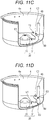
- FIG. 11C is a perspective view, partly in section, of the positional relationship of FIG. 10C
- FIG. 11D is a perspective view, partly in section, of the positional relationship of FIG. 10D .
- obstacle 4A is provided to extend in an up-and-down direction and to project from inner peripheral surface 4a of cooking container 4 toward the center of cooking container 4.
- An amount of projection of obstacle 4A toward the center of cooking container 4 is, for example, 6 mm.
- Obstacle 4A is, for example, semicircular in horizontal section.
- Lower end portion 4Aa of obstacle 4A is formed to curve along corner part 4B between the bottom surface and inner peripheral surface 4a of cooking container 4.
- a starting end of lower end portion 4Aa of obstacle 4A is positioned on the bottom surface of cooking container 4.
- a triangular area defined by blade 31 and an end face of obstacle 4A moves upward along with the rotation of blade 31.
- motor 9 is driven to transmit its rotational force to stirring body 20 via the magnetic coupling formed by driving magnet 7 and driven magnet 23, so that stirring body 20 rotates in rotating direction X1.
- Blade 31 of stirring body 20 then pushes cooking material C1 toward inner peripheral surface 4a of cooking container 4 as shown in FIGS. 10A and 11A .
- cooking material C1 rotating together with blade 31 while failing to ride on second stirring region E2 and third stirring region E3 of blade 31 is caught between blade 31 and obstacle 4A along with rotation of blade 31.
- cooking material C1 is moved in such a manner as to be raised along a curve of lower end portion 4Aa of obstacle 4A as shown in FIGS 10B and 11B as a result of the triangular area that is defined by blade 31 and the end face of obstacle 4A moving upward.
- stirring body 20 rotates further in rotating direction X1
- cooking material C1 is pushed by third stirring region E3 of blade 31 as shown in FIGS. 10C and 11C , thus moving upward along obstacle 4A.
- cooking material C1 reaches the top of third stirring region E3 of blade 31 as shown in FIGS. 10D and 11D . Thereafter or in this stage, cooking material C1 climbs over third stirring region E3 or falls along a slope of third stirring region E3 that slopes toward housing 21. This is when cooking material C1 experiences turning force effected by the potential energy and thus turns over.
- blade 31 is formed to curve convexly toward the downstream side in rotating direction X1 of housing 21 in a plan view and to have its front edge 32 positioned below rear edge 33 near housing 21. With this structure, the cooking materials can be moved toward inner peripheral surface 4a of cooking container 4.
- leading end portion 34 of blade 31 is formed to curve along inner peripheral surface 4a of cooking container 4 in the plan view and to slope upward toward the upstream side in rotating direction X1.
- the cooking materials can be turned over easily by going up leading end portion 34 of blade 31 along with the rotation of stirring body 20.
- front edge 32 is formed to be positioned above rear edge 33 near leading end portion 34 of blade 31.
- both the relatively small and large cooking materials can be cooked more uniformly.
- front edge 32 and rear edge 33 are formed to be positioned at an identical height or substantially identical height near inner peripheral surface 4a of cooking container 4. This structure more reliably enables the cooking materials positioned near inner peripheral surface 4a of cooking container 4 to climb over blade 31.
- blade 31 is formed by twisting the one plate member.
- This structure does not have a complicated shape as compared with a blade of stirring body 100 of PTL 1, so that blade 31 can be formed with ease.
- metal can be used as material for blade 31.
- obstacle 4A is provided on inner peripheral surface 4a of cooking container 4, and the lower end portion of obstacle 4A is formed to curve along corner part 4B of cooking container 4.
- This structure enables further reduction of a clearance between blade 31 and obstacle 4A, so that the clearance between blade 31 and inner peripheral surface 4a of cooking container 4 can be prevented from being clogged with larger cooking materials, thereby preventing the rotation of blade 31 from being stopped.
- at least one obstacle 4A may be provided on inner peripheral surface 4a of cooking container 4.
- stirring body 20 is detachably mounted to the center of the bottom surface of cooking container 4 via the magnetic coupling.
- This structure eliminates, for example, the need for a through hole in the bottom of cooking container 4 for passage of a shaft that serves as a rotating shaft for transmitting the rotational force to stirring body 20.
- this structure enables stirring body 20 to move to such an extent that magnetic force acts to relieve a load even in cases where the clearance between blade 31 and inner peripheral surface 4a (or obstacle 4A) of cooking container 4 is clogged with the cooking materials.
- the rotation of blade 31 can be prevented from being stopped.
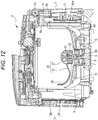
- FIG. 12 is a sectional view of a heating cooker according to the second exemplary embodiment of the present invention.
- FIG. 13 is a plan view illustrating the heating cooker of FIG. 12 with a lid removed therefrom.
- FIG. 14 is a perspective view of a stirring body of the heating cooker of FIG. 12 .
- the heating cooker of the second exemplary embodiment differs from the heating cooker of the first exemplary embodiment in that leading end portion 34 of blade 31 is provided with vertical wall 35 standing upward from front edge 32 along inner peripheral surface 4a of cooking container 4.
- Vertical wall 35 functions to inhibit cooking materials that ride on third stirring region E3 along with rotation of blade 31 from falling toward and adhering to inner peripheral surface 4a of cooking container 4.
- a section corresponding to vertical wall 35 is referred to as "fourth stirring region E4" as shown in FIG. 14 .
- fourth stirring region E4 can inhibit the cooking materials from adhering to inner peripheral surface 4a of cooking container 4, so that both the relatively small and large cooking materials can be cooked more uniformly.
- the starting end of lower end portion 4Aa of obstacle 4A is positioned on the bottom surface of cooking container 4; however, the present invention is not limited to this.
- the starting end of lower end portion 4Aa of obstacle 4A may be positioned, for example, on corner part 4B of cooking container 4.
- blade 31 is formed by twisting one plate member; however, the present invention is not limited to this.
- blade 31 may be formed of resin in a three-dimensional manner by injection molding.
- the present invention enables more uniform cooking of both the relatively small and large cooking materials and is thus useful for heating cookers each having a stirring function.
Landscapes
- Engineering & Computer Science (AREA)
- Food Science & Technology (AREA)
- Mechanical Engineering (AREA)
- Food-Manufacturing Devices (AREA)
- Cookers (AREA)
- Baking, Grill, Roasting (AREA)
- Frying-Pans Or Fryers (AREA)
- Mixers With Rotating Receptacles And Mixers With Vibration Mechanisms (AREA)
- Mixers Of The Rotary Stirring Type (AREA)
Abstract
Description
- The present invention relates to a heating cooker having a stirring function that includes a stirring body configured to stir cooking materials in a cooking container.
- Conventional heating cookeres of this type are described with reference to
FIGS. 15 to 17 . -
FIG. 15 is a perspective view of a stirring body of one of the conventional heating cookers. As shown inFIG. 15 ,stirring body 100 includes pushingpart 101 that pushes cooking materials toward an inner peripheral surface of a cooking container, andturnover part 102 that turns over the cooking materials positioned near the inner peripheral surface of the cooking container toward a center of the cooking container while stirringbody 100 rotates on rotation axis 100A inside the cooking container. Pushingpart 101 is formed to curve convexly toward a downstream side in rotating direction X100 in a plan view and to reduce in height towardturnover part 102.Turnover part 102 hasfirst slope 102A sloping upward toward an upstream side in rotating direction X100, andsecond slope 102B that is adjacent tofirst slope 102A and slopes downward from an apex offirst slope 102A toward rotation axis A100 (refer to, for example, PTL 1). -
FIG. 16 is a plan view of a stirring body of the other conventional heating cooker, andFIG. 17 is a side view of that stirring body. As shown inFIGS. 16 and 17 , stirringbody 200 includesblade 201 that curves convexly toward a downstream side in rotating direction X200 in a plan view. Blade 201 is a substantially plate-shaped member that is provided to slope upward toward an upstream side in rotating direction X200 throughout its overall length. Moreover,blade 201 is formed to reduce in height in a direction away from rotation axis A200 and to increase in height slightly at its leading end portion. In other words,blade 201 has gently slopingdepression 201B that is formed closer to rotation axis A200 than its leading end portion is.Blade 201 is also provided with, at a center of its upstream side in rotating direction X200,fin 202 that extends in a direction substantially orthogonal to an extending direction ofblade 201.Fin 202 is formed to be higher than an upper edge of blade 201 (refer to, for example, PTL 2). -
- PTL 1: Japanese Patent No.
5,250,428 - PTL 2: Japanese Translation of
PCT Publication No. 2014-533544 - In cases where the heating cooker of
PTL 1 is used to cook relatively large cooking materials such as materials for french fries, such cooking materials are generally pushed toward the inner peripheral surface of the cooking container by pushingpart 101 along with the rotation of stirringbody 100 in rotating direction X100. The cooking materials pushed toward the inner peripheral surface of the cooking container go up to the apex offirst slope 102A ofturnover part 102 alongfirst slope 102A as a result of their movement away from rotation axis A100 being restricted by the inner peripheral surface and fall alongsecond slope 102B toward rotation axis A100. Here, turning force acts on these cooking materials, so that these cooking materials turn over. As a result, uneven heating is conceivably reduced. - On the other hand, in cases where the heating cooker of
PTL 1 is used to cook relatively small cooking materials such as minced onions, such cooking materials generally move in a manner similar to the large cooking materials in an initial stage of heating. In other words, these cooking materials move along pushingpart 101,first slope 102A and thensecond slope 102B, thereby turning over. - However, as the heating proceeds, these cooking materials start to release moisture. This is when the cooking materials adhere easily to stirring
body 100, and resistance from a bottom surface of the cooking container reduces. For this reason, it becomes difficult for pushingpart 101 to move these cooking materials toward the inner peripheral surface of the cooking container, and it also becomes difficult for the cooking materials to go upfirst slope 102A ofturnover part 102. Moreover,first slope 102A is provided to be parallel to a radial direction and thus does not have such a component as to direct the cooking materials toward rotation axis A100. For this reason,first slope 102A serves as a dam and thus easily causes the cooking materials to rotate together with stirringbody 100. As a result, the same area of the cooking materials is continuously heated, thus resulting in uneven heating. - In cases where the heating cooker of
PTL 2 is used to cook relatively small cooking materials such as minced onions, such cooking materials are generally pushed toward an inner peripheral surface of a cooking container byblade 201. The cooking materials pushed toward the inner peripheral surface of the cooking container move in such a manner as to climb overdepression 201B becausedepression 201B is low-profile. This phenomenon takes place not only in an initial stage of heating but also in a later stage of heating because when the cooking materials increase in number near the inner peripheral surface of the cooking container, the cooking materials can climb overdepression 201B with ease. Consequently, the cooking materials are restrained from rotating together with stirringbody 200. - On the other hand, in cases where the heating cooker of
PTL 2 is used to cook relatively large cooking materials such as materials for french fries, some of the cooking materials go upblade 201, come into contact withfin 202 and get overblade 201. Here, turning force acts on those cooking materials, so that those cooking materials turn over. However, many of the cooking materials are generally pushed toward the inner peripheral surface of the cooking container byblade 201 and make such a movement as to climb overdepression 201B as in the case of the small cooking materials. In this case, weaker turning force acts on the cooking materials becausedepression 201B is low-profile, so that it is difficult to turn over the cooking materials. As a result, the same area of the cooking materials is continuously heated, thus resulting in uneven heating. - Therefore, there is still room for improvement in each of the heating cookers disclosed in
PTL 1 andPTL 2 in view of more uniform cooking of both the relatively small and large cooking materials. - The present invention provides a heating cooker having a stirring function that is capable of more uniform cooking of both the relatively small and large cooking materials.
- A heating cooker having a stirring function according to the present invention includes a stirring body that is configured to stir cooking materials housed in a cooking container. The stirring body includes a housing rotatably mounted to a center of a bottom surface of the cooking container, and a blade that extends from an outer peripheral surface of the housing toward an inner peripheral surface of the cooking container and curves convexly toward a downstream side in a rotating direction of the housing in a plan view. The blade has a front edge positioned on the downstream side in the rotating direction, and a rear edge positioned on an upstream side in the rotating direction relative to the front edge. A leading end portion of the blade curves along the inner peripheral surface of the cooking container in the plan view and slopes upward toward the upstream side in the rotating direction. The front edge is positioned below the rear edge near the housing and is positioned above the rear edge near the leading end portion.
- With this structure, both the relatively small and large cooking materials can be cooked more uniformly.
-
-
FIG. 1 is a perspective view of a heating cooker according to a first exemplary embodiment of the present invention. -
FIG. 2 is a sectional view of the heating cooker according to the first exemplary embodiment of the present invention. -
FIG. 3 is a plan view illustrating the heating cooker with a lid removed according to the first exemplary embodiment of the present invention. -
FIG. 4 is a perspective view of a stirring body of the heating cooker according to the first exemplary embodiment of the present invention. -
FIG. 5 is a side view of the stirring body of the heating cooker according to the first exemplary embodiment of the present invention. -
FIG. 6 is a plan view of the stirring body of the heating cooker according to the first exemplary embodiment of the present invention. -
FIG. 7A is a sectional view taken along 7A-7A ofFIG. 6 . -
FIG. 7B is a sectional view taken along 7B-7B ofFIG. 6 . -
FIG. 7C is a sectional view taken along 7C-7C ofFIG. 6 . -
FIG. 7D is a sectional view taken along 7D-7D ofFIG. 6 . -
FIG. 7E is a sectional view taken along 7E-7E ofFIG. 6 . -
FIG. 7F is a sectional view taken along 7F-7F ofFIG. 6 . -
FIG. 8A is a plan view illustrating the stirring body stirring cooking materials in the heating cooker according to the first exemplary embodiment of the present invention. -
FIG. 8B is a plan view illustrating the stirring body stirring the cooking materials in the heating cooker according to the first exemplary embodiment of the present invention. -
FIG. 8C is a plan view illustrating the stirring body stirring the cooking materials in the heating cooker according to the first exemplary embodiment of the present invention. -
FIG. 8D is a plan view illustrating the stirring body stirring the cooking materials in the heating cooker according to the first exemplary embodiment of the present invention. -
FIG. 9A is a sectional view taken along 9A-9A ofFIG. 8A . -
FIG. 9B is a sectional view taken along 9B-9B ofFIG. 8B . -
FIG. 9C is a sectional view taken along 9C-9C ofFIG. 8C . -
FIG. 9D is a sectional view taken along 9D-9D ofFIG. 8D . -
FIG. 10A is a plan view illustrating a positional relationship among the stirring body, an obstacle, and a cooking material when the stirring body stirs a cooking material in the heating cooker according to the first exemplary embodiment of the present invention. -
FIG. 10B is a plan view illustrating a positional relationship among the stirring body, the obstacle, and the cooking material when the stirring body stirs the cooking material in the heating cooker according to the first exemplary embodiment of the present invention. -
FIG. 10C is a plan view illustrating a positional relationship among the stirring body, the obstacle, and the cooking material when the stirring body stirs the cooking material in the heating cooker according to the first exemplary embodiment of the present invention. -
FIG. 10D is a plan view illustrating a positional relationship among the stirring body, the obstacle, and the cooking material when the stirring body stirs the cooking material in the heating cooker according to the first exemplary embodiment of the present invention. -
FIG. 11A is a perspective view, partly in section, of the heating cooker having the positional relationship shown inFIG. 10A according to the first exemplary embodiment of the present invention. -
FIG. 11B is a perspective view, partly in section, of the heating cooker having the positional relationship shown inFIG. 10B according to the first exemplary embodiment of the present invention. -
FIG. 11C is a perspective view, partly in section, of the heating cooker having the positional relationship shown inFIG. 10C according to the first exemplary embodiment of the present invention. -
FIG. 11D is a perspective view, partly in section, of the heating cooker having the positional relationship shown inFIG. 10D according to the first exemplary embodiment of the present invention. -
FIG. 12 is a sectional view of a heating cooker according to a second exemplary embodiment of the present invention. -
FIG. 13 is a plan view illustrating the heating cooker with a lid removed according to the second exemplary embodiment of the present invention. -
FIG. 14 is a perspective view of a stirring body of the heating cooker according to the second exemplary embodiment of the present invention. -
FIG. 15 is a perspective view of a stirring body of a conventional heating cooker. -
FIG. 16 is a plan view of a stirring body of another conventional heating cooker. -
FIG. 17 is a side view of the stirring body of the other conventional heating cooker. - Exemplary embodiments of the present invention are described hereinafter with reference to the accompanying drawings. It is to be noted that the exemplary embodiments described hereinafter are not restrictive of the present invention.
- A heating cooker according to the first exemplary embodiment of the present invention is a heating cooker having a stirring function that includes a stirring body configured to stir cooking materials housed in a cooking container.
FIG. 1 is a perspective view of the heating cooker according to the present exemplary embodiment.FIG. 2 is a sectional view of the heating cooker according to the present exemplary embodiment. - As shown in
FIG. 1 , the heating cooker of the present exemplary embodiment includesapparatus body 1 having a substantially bottomed cylindrical shape, andlid 2 that openably covers an upper opening ofapparatus body 1. As shown inFIG. 2 ,lid 2 is rotatably mounted to hinge part 1A provided at an upper rear part (upper right inFIG. 2 ) ofapparatus body 1. -
Apparatus body 1 has, at its front,operation unit 3 provided for various operations including selection of a cooking menu.Operation unit 3 includes operationkey group 3A anddisplay 3B. Operationkey group 3A includes, for example, a start key, a cancel key, and a select key used for, for example, selecting the cooking menu.Display 3B is formed of, for example, a liquid crystal display panel and displays various pieces of information such as information set by means of the operation key group. - As shown in
FIG. 2 , storage part 5 having a bottomed cylindrical shape is providedinside apparatus body 1 to receivedetachable cooking container 4. Substantiallycylindrical motor holder 6 is provided at a bottom center of storage part 5 in such a manner as to partly pass through the bottom center of storage part 5. Ring-shapeddriving magnet 7 andmagnet holder 8 for holdingdriving magnet 7 are provided insidemotor holder 6.Motor 9 that generates rotational driving force has itsdrive shaft 9A inserted into a center ofmagnet holder 8.Motor 9 is provided externally of storage part 5 and is held by the motor holder. Asmotor 9 is driven,drive shaft 9A rotates on its axis, andmagnet holder 8 and drivingmagnet 7 rotate accordingly. -
Heater 10 is provided externally ofmotor holder 6 and at an inner bottom of storage part 5 forheating cooking container 4. In the present exemplary embodiment,heater 10 is a sheathed heater that transmits heat by contact with a bottom wall ofcooking container 4.Heater 10 is formed to be substantially annular and is provided in a position opposed to an outer peripheral portion of the bottom wall ofcooking container 4. -
Controller 11 controls driving ofmotor 9 and driving ofheater 10.Controller 11 is disposed externally of storage part 5 butinside apparatus body 1. Based on various pieces of information set by means ofoperation unit 3 and through use of, for example, a temperature sensor (not illustrated) providedinside apparatus body 1,controller 11 controls driving of parts anddevices including motor 9 andheater 10. -
Cooking container 4 is a container capable of housing a plurality of cooking materials including relatively large cooking materials such as materials for french fries or relatively small cooking materials such as minced onions. Insidecooking container 4, stirringbody 20 that stirs the cooking materials is provided. - Stirring
body 20 includeshousing 21 rotatably mounted to a center of a bottom surface ofcooking container 4, andblade 31 extending from an outer peripheral surface ofhousing 21 toward innerperipheral surface 4a ofcooking container 4. - Inside
housing 21, there are providedshaft 22 that serves as a rotating shaft, and ring-shaped drivenmagnet 23 disposed to surroundshaft 22. Drivenmagnet 23 and drivingmagnet 7 mentioned above form a magnetic coupling. Stirringbody 20 is detachably mounted to the center of the bottom surface ofcooking container 4 via the magnetic coupling and rotates on an axis ofshaft 22 whenmotor 9 is driven. -
FIG. 3 is a plan view illustrating the heating cooker ofFIG. 1 withlid 2 removed therefrom. As shown inFIG. 3 ,blade 31 of stirringbody 20 is formed to curve convexly toward a downstream side in rotating direction X1 ofhousing 21 in the plan view.Blade 31 hasfront edge 32 positioned on the downstream side in rotating direction X1, andrear edge 33 positioned on an upstream side in rotating direction X1 relative tofront edge 32. Leadingend portion 34 ofblade 31 is formed to curve along innerperipheral surface 4a ofcooking container 4 in the plan view. It is to be noted that leadingend portion 34 ofblade 31 is not limited to a leading end portion that curves with exactly the same curvature as innerperipheral surface 4a ofcooking container 4 but may curve with substantially the same curvature as innerperipheral surface 4a ofcooking container 4. - Inner
peripheral surface 4a ofcooking container 4 is provided withobstacle 4A that extends in an up-and-down direction and projects toward a center ofcooking container 4. Leadingend portion 34 ofblade 31 is spaced a predetermined clearance away from innerperipheral surface 4a ofcooking container 4 so as not to come into contact withobstacle 4A during rotation around the axis ofshaft 22. A detailed description ofobstacle 4A will be given later. -
FIG. 4 is a perspective view of stirringbody 20, andFIG. 5 is a side view of stirringbody 20.FIG. 6 is a plan view of stirringbody 20.FIG. 7A is a sectional view taken along 7A-7A ofFIG. 6 ,FIG. 7B is a sectional view taken along 7B-7B ofFIG. 6 , andFIG. 7C is a sectional view taken along 7C-7C ofFIG. 6 .FIG. 7D is a sectional view taken along 7D-7D ofFIG. 6 ,FIG. 7E is a sectional view taken along 7E-7E ofFIG. 6 , andFIG. 7F is a sectional view taken along 7F-7F ofFIG. 6 . - As shown
FIGS. 3 to 7F ,blade 31 is formed by twisting one plate member in the present exemplary embodiment.Front edge 32 ofblade 31 is positioned belowrear edge 33 nearhousing 21. In other words,blade 31 is formed to slope upward toward an upstream side in rotating direction X1 nearhousing 21. A portion ofblade 31 that is nearhousing 21 functions to push the cooking materials toward innerperipheral surface 4a ofcooking container 4 along with the rotation ofblade 31. In the present exemplary embodiment, a functional region ofblade 31 that includes this portion nearhousing 21 is referred to as "first stirring region E1". - It is to be noted that when a junction between
blade 31 andhousing 21 is inclined at angle θ1 of not less than 50° with respect to plane S1 parallel to rotating direction X1 as shown inFIG. 7A , small cooking materials having moist surfaces adhere to first stirring region E1 ofblade 31, therefore, stirring force toward innerperipheral surface 4a ofcooking container 4 is reduced. On the other hand, when inclined angle θ1 is not more than 10°, large cooking materials climb over first stirring region E1 ofblade 31 with ease, thus resulting in reduced stirring force in the direction toward innerperipheral surface 4a ofcooking container 4. For the above reason, inclined angle θ1 preferably ranges from 20° to 40°, and it is more preferable that inclined angle θ1 ranges from 30° to 40°. -
Blade 31 is formed so that a height ofrear edge 33 reduces in a direction away from the outer peripheral surface ofhousing 21 andfront edge 32 andrear edge 33 are formed to be positioned at an identical height or substantially identical height near innerperipheral surface 4a ofcooking container 4 as shown inFIGS. 7C and7D . A portion ofblade 31 that is near innerperipheral surface 4a ofcooking container 4 functions to allow the cooking materials to climb overblade 31 along with the rotation ofblade 31. In the present exemplary embodiment, the region having such a function is referred to as "second stirring region E2". - As shown in
FIGS. 4 and 5 , leadingend portion 34 ofblade 31 is formed to slope upward toward the upstream side in rotating direction X1. Along with the rotation ofblade 31, leadingend portion 34 ofblade 31 functions to bring up cooking materials accumulating near innerperipheral surface 4a ofcooking container 4 and turn over the cooking materials when the cooking materials fall. In the present exemplary embodiment, the region having such a function is referred to as "third stirring region E3". - It is to be noted that when
front edge 32 is inclined at leadingend portion 34 ofblade 31 at angle θ2 of not more than 20° with respect to plane S1 parallel to rotating direction X1 as shown inFIG. 5 , large cooking materials are difficult to turn over. On the other hand, when inclined angle θ2 is not less than 60°, leadingend portion 34 ofblade 31 serves as a dam and thus easily causes small cooking materials to rotate together withblade 31. As a result, the same area of the cooking materials is continuously heated, thus resulting in uneven heating. In this case, torque for rotation ofblade 31 also needs to be increased. For the above reason, inclined angle θ2 preferably ranges from 30° to 50°, and it is more preferable that inclined angle θ2 ranges from 30° to 40°. - As shown in
FIGS. 7E and 7F ,rear edge 33 is positioned to be belowfront edge 32 and to be closer tohousing 21 thanfront edge 32 is near leadingend portion 34 ofblade 31. In other words,front edge 32 is positioned aboverear edge 33 near leadingend portion 34 ofblade 31. This means that leadingend portion 34 ofblade 31 is formed to slope downward towardhousing 21. Thus, the cooking materials that go up leadingend portion 34 ofblade 31 along with the rotation ofblade 31 fall easily toward housing 21 (toward an upstream side of second stirring region E2 in rotating direction X1). Consequently, with leadingend portion 34 ofblade 31 prevented from becoming a dam, a flow that causes the cooking materials to climb over second stirring region E2 and third stirring region E3 ofblade 31 while turning over can be generated, thus enabling more uniform heating of the cooking materials. With leadingend portion 34 ofblade 31 sloping downward towardhousing 21, a direction of drag on the cooking materials at leadingend portion 34 is a direction inclined toward a rotation center relative to a tangential direction of rotation. For this reason, reaction force has a smaller component in the tangential direction of rotation, so that a load of the cooking materials onblade 31 can be reduced, and the torque for rotation ofblade 31 can be reduced accordingly. - As shown in
FIG. 5 , upper end P1 of leadingend portion 34 ofblade 31 is positioned above upper end P2 of the junction betweenblade 31 andhousing 21. Accordingly, the cooking materials that go up leadingend portion 34 ofblade 31 along with the rotation ofblade 31 can have increased potential energy and thus can be turned over more reliably. - As shown in
FIG. 6 andFIGS. 7A to 7F , a shortest distance betweenfront edge 32 andrear edge 33 in a cross section taken along rotating direction X1 shortens toward leadingend portion 34 in a plan view. Accordingly, the load of the cooking materials onblade 31 can be reduced, and thus the torque for rotation ofblade 31 can be reduced. - A description will be given next of a stirring operation of stirring
body 20 performed on the cooking materials. -
FIGS. 8A to 8D are plan views eachillustrating stirring body 20 stirring the cooking materials.FIG. 9A is a sectional view taken along 9A-9A ofFIG. 8A ,FIG. 9B is a sectional view taken along 9B-9B ofFIG. 8B ,FIG. 9C is a sectional view taken along 9C-9C ofFIG. 8C , andFIG. 9D is a sectional view taken along 9D-9D ofFIG. 8D . - The following description refers to a case where relatively small materials such as minced onions are cooked.
- First,
motor 9 is driven to transmit its rotational force to stirringbody 20 via the magnetic coupling formed by drivingmagnet 7 and drivenmagnet 23, thus stirringbody 20 rotates in rotating direction X1. Accordingly,blade 31 of stirringbody 20 comes into contact with the cooking materials as shown inFIGS. 8A and9A . - As stirring
body 20 rotates further in rotating direction X1, first stirring region E1 pushes cooking materials that are near housing 21 (i.e., cooking materials hatched by oblique lines inFIGS. 8A to 8D andFIGS. 9A to 9D ) toward innerperipheral surface 4a ofcooking container 4 as shown inFIGS. 8B and9B . Thus, there are present cooking materials that move along a direction of arrow M2 in whichfront edge 32 ofblade 31 is defined and cooking materials that move in a direction of arrow M1 in such a manner as to ride on first stirring region E1. Here, cooking materials that are near second stirring region E2 (i.e., cooking materials provided with a sand hatch pattern inFIGS. 8A to 8D andFIGS. 9A to 9D ) are pushed by the cooking materials moving in the direction of arrow M2 and have their movement away fromhousing 21 restricted by innerperipheral surface 4a ofcooking container 4, thereby moving in a direction of arrow M3 in such a manner as to ride on second stirring region E2. It is to be noted here that because second stirring region E2 is at a low height, both the large and small cooking materials can ride on second stirring region E2 with ease. - Thereafter, as stirring
body 20 rotates further in rotating direction X1, some of the cooking materials riding on second stirring region E2 after being pushed toward innerperipheral surface 4a of the cooking container go up in a direction of arrow M5 and ride on third stirring region E3 as shown inFIGS. 8C and9C . A remainder of these cooking materials climbs over second stirring region E2 in a direction of arrow M4 and fall in the direction of arrow M4 from an upstream side ofblade 31 in rotating direction X1. Moreover, some of the cooking materials riding on first stirring region E1 are caused by following cooking materials that move fromhousing 21 to ride on first stirring region E1 to fall from the rear edge where first stirring region E1 is somewhat lower in height. A remainder of those cooking materials is caused by following cooking materials that move fromhousing 21 to ride on first stirring region E1 to climb over second stirring region E2 in a direction of arrow M6 and fall toward the upstream side in rotating direction X1. - Thereafter, as stirring
body 20 rotates further in rotating direction X1, the cooking materials that has gone up third stirring region E3 and approached a top of third stirring region E3 fall in a direction of arrow M10 from the upstream side ofblade 31 in rotating direction X1 as shown inFIGS. 8D and9D . This is when strong turning force effected by the increased potential energy acts on the cooking materials climbing over third stirring region E3, thus these cooking materials turn over easily. For this reason, whether cooking materials are large or small, the cooking materials can be turned over. - By the operation described above, the cooking materials that are near
housing 21 before the rotation of stirring body 20 (i.e., the cooking materials hatched by the oblique lines inFIGS. 8A and9A ) and the cooking materials that are near second stirring region E2 before the rotation of stirring body 20 (i.e., the cooking materials provided with the sand hatch pattern inFIGS. 8A and9A ) are mixed together as shown inFIGS. 8D and9D and stirred. Accordingly, the cooking materials are heated uniformly byheater 10 viacooking container 4. - While stirring
body 20 is rotated in rotating direction X1, the motions shown inFIGS. 8A to 8D andFIGS. 9A to 9D are repeated. In this way, the cooking materials are stirred more uniformly. - The detailed description of
obstacle 4A provided on innerperipheral surface 4a ofcooking container 4 will be given next. -
FIGS. 10A to 10D are plan views each illustrating a positional relationship among stirringbody 20,obstacle 4A and a cooking material when stirringbody 20 stirs the cooking material.FIG. 11A is a perspective view, partly in section, of the positional relationship ofFIG. 10A ,FIG. 11B is a perspective view, partly in section, of the positional relationship ofFIG. 10B ,FIG. 11C is a perspective view, partly in section, of the positional relationship ofFIG. 10C , andFIG. 11D is a perspective view, partly in section, of the positional relationship ofFIG. 10D . - As shown in
FIGS. 2 and11A ,obstacle 4A is provided to extend in an up-and-down direction and to project from innerperipheral surface 4a ofcooking container 4 toward the center ofcooking container 4. An amount of projection ofobstacle 4A toward the center ofcooking container 4 is, for example, 6 mm.Obstacle 4A is, for example, semicircular in horizontal section. - Lower end portion 4Aa of
obstacle 4A is formed to curve alongcorner part 4B between the bottom surface and innerperipheral surface 4a ofcooking container 4. A starting end of lower end portion 4Aa ofobstacle 4A is positioned on the bottom surface ofcooking container 4. Thus, a triangular area defined byblade 31 and an end face ofobstacle 4A moves upward along with the rotation ofblade 31. - First,
motor 9 is driven to transmit its rotational force to stirringbody 20 via the magnetic coupling formed by drivingmagnet 7 and drivenmagnet 23, so that stirringbody 20 rotates in rotating direction X1.Blade 31 of stirringbody 20 then pushes cooking material C1 toward innerperipheral surface 4a ofcooking container 4 as shown inFIGS. 10A and11A . Here, cooking material C1 rotating together withblade 31 while failing to ride on second stirring region E2 and third stirring region E3 ofblade 31 is caught betweenblade 31 andobstacle 4A along with rotation ofblade 31. - Thereafter, as stirring
body 20 rotates further in rotating direction X1, cooking material C1 is moved in such a manner as to be raised along a curve of lower end portion 4Aa ofobstacle 4A as shown inFIGS 10B and11B as a result of the triangular area that is defined byblade 31 and the end face ofobstacle 4A moving upward. - Thereafter, as stirring
body 20 rotates further in rotating direction X1, cooking material C1 is pushed by third stirring region E3 ofblade 31 as shown inFIGS. 10C and11C , thus moving upward alongobstacle 4A. - Thereafter, as stirring
body 20 rotates further in rotating direction X1, cooking material C1 reaches the top of third stirring region E3 ofblade 31 as shown inFIGS. 10D and11D . Thereafter or in this stage, cooking material C1 climbs over third stirring region E3 or falls along a slope of third stirring region E3 that slopes towardhousing 21. This is when cooking material C1 experiences turning force effected by the potential energy and thus turns over. - According to the heating cooker of the present exemplary embodiment,
blade 31 is formed to curve convexly toward the downstream side in rotating direction X1 ofhousing 21 in a plan view and to have itsfront edge 32 positioned belowrear edge 33 nearhousing 21. With this structure, the cooking materials can be moved toward innerperipheral surface 4a ofcooking container 4. - According to the heating cooker of the present exemplary embodiment, leading
end portion 34 ofblade 31 is formed to curve along innerperipheral surface 4a ofcooking container 4 in the plan view and to slope upward toward the upstream side in rotating direction X1. With this structure, the cooking materials can be turned over easily by going up leadingend portion 34 ofblade 31 along with the rotation of stirringbody 20. - According to the heating cooker of the present exemplary embodiment,
front edge 32 is formed to be positioned aboverear edge 33 near leadingend portion 34 ofblade 31. With this structure, the cooking materials that go up leadingend portion 34 ofblade 31 along with the rotation ofblade 31 fall easily in the direction away from innerperipheral surface 4a ofcooking container 4. - As a result, both the relatively small and large cooking materials can be cooked more uniformly.
- According to the heating cooker of the present exemplary embodiment,
front edge 32 andrear edge 33 are formed to be positioned at an identical height or substantially identical height near innerperipheral surface 4a ofcooking container 4. This structure more reliably enables the cooking materials positioned near innerperipheral surface 4a ofcooking container 4 to climb overblade 31. - According to the heating cooker of the present exemplary embodiment,
blade 31 is formed by twisting the one plate member. This structure does not have a complicated shape as compared with a blade of stirringbody 100 ofPTL 1, so thatblade 31 can be formed with ease. In addition, metal can be used as material forblade 31. - According to the heating cooker of the first exemplary embodiment,
obstacle 4A is provided on innerperipheral surface 4a ofcooking container 4, and the lower end portion ofobstacle 4A is formed to curve alongcorner part 4B ofcooking container 4. This structure enables further reduction of a clearance betweenblade 31 andobstacle 4A, so that the clearance betweenblade 31 and innerperipheral surface 4a ofcooking container 4 can be prevented from being clogged with larger cooking materials, thereby preventing the rotation ofblade 31 from being stopped. It is to be noted that at least oneobstacle 4A may be provided on innerperipheral surface 4a ofcooking container 4. - According to the heating cooker of the present exemplary embodiment, stirring
body 20 is detachably mounted to the center of the bottom surface ofcooking container 4 via the magnetic coupling. This structure eliminates, for example, the need for a through hole in the bottom ofcooking container 4 for passage of a shaft that serves as a rotating shaft for transmitting the rotational force to stirringbody 20. Moreover, this structure enables stirringbody 20 to move to such an extent that magnetic force acts to relieve a load even in cases where the clearance betweenblade 31 and innerperipheral surface 4a (orobstacle 4A) ofcooking container 4 is clogged with the cooking materials. Thus, the rotation ofblade 31 can be prevented from being stopped. -
FIG. 12 is a sectional view of a heating cooker according to the second exemplary embodiment of the present invention.FIG. 13 is a plan view illustrating the heating cooker ofFIG. 12 with a lid removed therefrom.FIG. 14 is a perspective view of a stirring body of the heating cooker ofFIG. 12 . The heating cooker of the second exemplary embodiment differs from the heating cooker of the first exemplary embodiment in thatleading end portion 34 ofblade 31 is provided withvertical wall 35 standing upward fromfront edge 32 along innerperipheral surface 4a ofcooking container 4. -
Vertical wall 35 functions to inhibit cooking materials that ride on third stirring region E3 along with rotation ofblade 31 from falling toward and adhering to innerperipheral surface 4a ofcooking container 4. In the present exemplary embodiment, a section corresponding tovertical wall 35 is referred to as "fourth stirring region E4" as shown inFIG. 14 . - According to the heating cooker of the present exemplary embodiment, fourth stirring region E4 can inhibit the cooking materials from adhering to inner
peripheral surface 4a ofcooking container 4, so that both the relatively small and large cooking materials can be cooked more uniformly. - It is to be noted that these exemplary embodiments are not restrictive of the present invention, and the present invention can be carried out in other various exemplary embodiments. For example, in the structure shown in
FIG. 11A , the starting end of lower end portion 4Aa ofobstacle 4A is positioned on the bottom surface ofcooking container 4; however, the present invention is not limited to this. The starting end of lower end portion 4Aa ofobstacle 4A may be positioned, for example, oncorner part 4B ofcooking container 4. - In each of the exemplary embodiments,
blade 31 is formed by twisting one plate member; however, the present invention is not limited to this. For example,blade 31 may be formed of resin in a three-dimensional manner by injection molding. - It is to be noted that any appropriate combination of the various embodiments can produce respective effects.
- The present invention enables more uniform cooking of both the relatively small and large cooking materials and is thus useful for heating cookers each having a stirring function.
-
- 1
- apparatus body
- 1A
- hinge part
- 2
- lid
- 3
- operation unit
- 3A
- operation key group
- 3B
- display
- 4
- cooking container
- 4a
- inner peripheral surface
- 4A
- obstacle
- 4Aa
- lower end portion
- 4B
- corner part
- 5
- storage part
- 6
- motor holder
- 7
- driving magnet
- 8
- magnet holder
- 9
- motor
- 9A
- drive shaft
- 10
- heater
- 11
- controller
- 20, 100, 200
- stirring body
- 21
- housing
- 22
- shaft
- 23
- driven magnet
- 31, 201
- blade
- 32
- front edge
- 33
- rear edge
- 34
- leading end portion
- 35
- vertical wall
Claims (12)
- A heating cooker having a stirring function, the heating cooker comprising a stirring body configured to stir cooking materials housed in a cooking container, wherein
the stirring body comprises:a housing rotatably mounted to a center of a bottom surface of the cooking container; anda blade extending from an outer peripheral surface of the housing toward an inner peripheral surface of the cooking container and curving convexly toward a downstream side in a rotating direction of the housing in a plan view, whereinthe blade has:a front edge positioned on the downstream side in the rotating direction; anda rear edge positioned on an upstream side in the rotating direction relative to the front edge,wherein a leading end portion of the blade curves along the inner peripheral surface of the cooking container in the plan view and slopes upward toward the upstream side in the rotating direction,the front edge is positioned below the rear edge near the housing, andthe front edge is positioned above the rear edge near the leading end portion. - The heating cooker according to claim 1, wherein the front edge and the rear edge are formed to be positioned at an identical height or substantially identical height near the inner peripheral surface of the cooking container.
- The heating cooker according to claim 1 or 2, wherein the rear edge is positioned closer to the housing than the front edge is near the leading end portion of the blade.
- The heating cooker according to any one of claims 1 to 3, wherein an upper end of the leading end portion of the blade is positioned above an upper end of a junction between the blade and the housing.
- The heating cooker according to any one of claims 1 to 4, wherein a shortest distance between the front edge and the rear edge in a cross section taken along the rotating direction shortens toward the leading end portion in a plan view.
- The heating cooker according to any one of claims 1 to 5, wherein the blade is formed by twisting one plate member.
- The heating cooker according to any one of claims 1 to 6, wherein the leading end portion of the blade is provided with a vertical wall standing upward from the front edge along the inner peripheral surface of the cooking container.
- The heating cooker according to any one of claims 1 to 7, wherein the junction between the blade and the housing is formed to be inclined at an angle ranging from 20° to 40° with respect to a plane parallel to the rotating direction.
- The heating cooker according to any one of claims 1 to 8, wherein at the leading end portion of the blade, the front edge is formed to be inclined at an angle ranging from 30° to 50° with respect to a plane parallel to the rotating direction.
- The heating cooker according to any one of claims 1 to 9, wherein
the inner peripheral surface of the cooking container is provided with at least one obstacle that extends in an up-and-down direction and projects toward a center of the cooking container; and
a lower end portion of the obstacle curves along a corner part between the bottom surface and the inner peripheral surface of the cooking container. - The heating cooker according to claim 10, wherein a starting end of the lower end portion of the obstacle is positioned on the bottom surface of the cooking container.
- The heating cooker according to any one of claims 1 to 11, wherein the stirring body is detachably mounted to the center of the bottom surface of the cooking container via a magnetic coupling.
Applications Claiming Priority (2)
| Application Number | Priority Date | Filing Date | Title |
|---|---|---|---|
| JP2015167692 | 2015-08-27 | ||
| PCT/JP2016/003569 WO2017033407A1 (en) | 2015-08-27 | 2016-08-03 | Heating cooker |
Publications (2)
| Publication Number | Publication Date |
|---|---|
| EP3342316A1 true EP3342316A1 (en) | 2018-07-04 |
| EP3342316A4 EP3342316A4 (en) | 2018-07-18 |
Family
ID=58099647
Family Applications (1)
| Application Number | Title | Priority Date | Filing Date |
|---|---|---|---|
| EP16838759.5A Withdrawn EP3342316A4 (en) | 2015-08-27 | 2016-08-03 | Heating cooker |
Country Status (7)
| Country | Link |
|---|---|
| US (1) | US10602868B2 (en) |
| EP (1) | EP3342316A4 (en) |
| JP (1) | JP6706764B2 (en) |
| CN (1) | CN107205564B (en) |
| CA (1) | CA2971831A1 (en) |
| RU (1) | RU2017127162A (en) |
| WO (1) | WO2017033407A1 (en) |
Cited By (2)
| Publication number | Priority date | Publication date | Assignee | Title |
|---|---|---|---|---|
| US20180184848A1 (en) * | 2015-06-12 | 2018-07-05 | De' Longhi Appliances S.R.L.Con Unico Socio | Apparatus for Cooking Foods |
| EP3912526A1 (en) | 2020-05-19 | 2021-11-24 | Seb S.A. | Blade for stirring food for a cooking appliance and corresponding appliance |
Families Citing this family (15)
| Publication number | Priority date | Publication date | Assignee | Title |
|---|---|---|---|---|
| ES2759917T3 (en) * | 2015-06-12 | 2020-05-12 | De Longhi Appliances Srl | Appliance with a mixing device for cooking food |
| WO2018139287A1 (en) * | 2017-01-27 | 2018-08-02 | パナソニックIpマネジメント株式会社 | Cooking device |
| US10899853B2 (en) | 2018-03-19 | 2021-01-26 | Exxonmobil Chemical Patents Inc. | Processes for producing high propylene content PEDM using tetrahydroindacenyl catalyst systems |
| US11142605B2 (en) | 2018-04-06 | 2021-10-12 | Exxonmobil Chemical Patents Inc. | Compatibilized thermoplastic vulcanizate compositions |
| KR102048656B1 (en) * | 2019-05-03 | 2020-01-08 | 김영희 | Roaster with slant supporter |
| CN114423838B (en) | 2019-07-17 | 2023-11-24 | 埃克森美孚化学专利公司 | Pressure sensitive adhesive comprising propylene-ethylene (-diene) copolymer |
| JP7297586B2 (en) * | 2019-07-31 | 2023-06-26 | エムケー精工株式会社 | feathers and food manufacturing equipment |
| DE102019134095A1 (en) * | 2019-12-12 | 2021-06-17 | Vorwerk & Co. Interholding Gmbh | Hotplate module for connecting to a kitchen appliance base and cooking system |
| CN115666773A (en) * | 2020-04-06 | 2023-01-31 | Prc-迪索托国际公司 | Mixing impeller for sealant cartridges |
| CN111839180B (en) * | 2020-07-07 | 2021-12-24 | 山东中科伺易智能技术有限公司 | Intelligent wheel-by-wheel operation opportunity identification platform |
| CA200996S (en) * | 2020-07-16 | 2021-11-24 | Midea Group Co Ltd | Pot lid |
| CA200979S (en) * | 2020-07-16 | 2021-11-25 | Midea Group Co Ltd | Multifunctional cooking pot |
| USD968157S1 (en) * | 2020-10-27 | 2022-11-01 | Midea Group Co., Ltd. | Cooking utensil |
| JP6991301B1 (en) | 2020-12-25 | 2022-01-12 | 隆昭 藤井 | Liquid agitator |
| FR3140527B1 (en) * | 2022-10-11 | 2024-10-18 | Seb Sa | Kitchen appliance comprising a guide element for a stirring blade |
Family Cites Families (15)
| Publication number | Priority date | Publication date | Assignee | Title |
|---|---|---|---|---|
| FR2634993B1 (en) * | 1988-07-06 | 1991-10-04 | Seb Sa | HOUSEHOLD APPLIANCE ROBOT COMPRISING A HEATING MIXER ACCESSORY |
| DE4414821A1 (en) * | 1994-04-28 | 1995-11-02 | Vorwerk Co Interholding | Food processor with a mixing vessel and a drive for an agitator in the mixing vessel |
| US6026735A (en) * | 1998-06-30 | 2000-02-22 | Waterworth; Ann | Self stirring cooking assembly |
| US6289793B1 (en) * | 2001-03-01 | 2001-09-18 | Tsann Kuen Usa, Inc. | Cooking appliance |
| CN2870694Y (en) * | 2005-11-29 | 2007-02-21 | 广东新宝电器股份有限公司 | Multifunctional pot with stirrer |
| FR2896677B1 (en) * | 2006-02-01 | 2010-08-20 | Seb Sa | COOKING APPARATUS WITH MEANS OF REMUTING AND METHOD THEREOF |
| US8430024B2 (en) * | 2010-03-04 | 2013-04-30 | Tall & Stout Industrial Corp. | Frying-and-baking oven and heating cover assembly thereof |
| US8480292B2 (en) * | 2010-06-01 | 2013-07-09 | Boris Dushine | Systems, apparatus and methods to reconstitute dehydrated drinks |
| US20120145140A1 (en) * | 2010-12-13 | 2012-06-14 | Tall & Stout Industrial Corp. | Turbo oven capable of stirring and turning food materials |
| CN102327049B (en) * | 2011-06-29 | 2014-01-22 | 周林斌 | Spring type automatic frying pan |
| EP2594177A1 (en) | 2011-11-17 | 2013-05-22 | Koninklijke Philips Electronics N.V. | Appliance for preparing foodstuff |
| US20140290499A1 (en) | 2011-11-17 | 2014-10-02 | Koninklijke Philips N.V. | Preparing foodstuff |
| CN102499576A (en) * | 2012-01-04 | 2012-06-20 | 黄世光 | Stirring cooking machine |
| CN203762844U (en) * | 2013-12-26 | 2014-08-13 | 广东伊莱特电器有限公司 | Multi-functional frying pan with improved structure |
| CN204541784U (en) * | 2015-03-25 | 2015-08-12 | 漆小兰 | A kind of intelligent frying pan double leaf stirs mechanism |
-
2016
- 2016-08-03 JP JP2017536201A patent/JP6706764B2/en active Active
- 2016-08-03 RU RU2017127162A patent/RU2017127162A/en not_active Application Discontinuation
- 2016-08-03 CA CA2971831A patent/CA2971831A1/en not_active Abandoned
- 2016-08-03 EP EP16838759.5A patent/EP3342316A4/en not_active Withdrawn
- 2016-08-03 CN CN201680008017.9A patent/CN107205564B/en active Active
- 2016-08-03 WO PCT/JP2016/003569 patent/WO2017033407A1/en not_active Ceased
- 2016-08-03 US US15/531,955 patent/US10602868B2/en not_active Expired - Fee Related
Cited By (6)
| Publication number | Priority date | Publication date | Assignee | Title |
|---|---|---|---|---|
| US20180184848A1 (en) * | 2015-06-12 | 2018-07-05 | De' Longhi Appliances S.R.L.Con Unico Socio | Apparatus for Cooking Foods |
| US10856696B2 (en) * | 2015-06-12 | 2020-12-08 | De' Longhi Appliances S.R.L. Con Unico Socio | Apparatus for cooking foods |
| EP3912526A1 (en) | 2020-05-19 | 2021-11-24 | Seb S.A. | Blade for stirring food for a cooking appliance and corresponding appliance |
| FR3110374A1 (en) | 2020-05-19 | 2021-11-26 | Seb S.A. | Food stirring paddle for cooking appliance and corresponding appliance |
| EP4234075A2 (en) | 2020-05-19 | 2023-08-30 | Seb S.A. | Blade for stirring food for a cooking appliance and corresponding appliance |
| EP4234075A3 (en) * | 2020-05-19 | 2023-10-18 | Seb S.A. | Blade for stirring food for a cooking appliance and corresponding appliance |
Also Published As
| Publication number | Publication date |
|---|---|
| WO2017033407A1 (en) | 2017-03-02 |
| CN107205564B (en) | 2020-07-24 |
| CN107205564A (en) | 2017-09-26 |
| US20170360237A1 (en) | 2017-12-21 |
| EP3342316A4 (en) | 2018-07-18 |
| JP6706764B2 (en) | 2020-06-10 |
| JPWO2017033407A1 (en) | 2018-06-14 |
| CA2971831A1 (en) | 2017-03-02 |
| RU2017127162A3 (en) | 2019-09-30 |
| US10602868B2 (en) | 2020-03-31 |
| RU2017127162A (en) | 2019-09-30 |
Similar Documents
| Publication | Publication Date | Title |
|---|---|---|
| EP3342316A1 (en) | Heating cooker | |
| US10610050B2 (en) | Heating cooker | |
| JP7126047B2 (en) | heating cooker | |
| KR101987504B1 (en) | Food cooking appliance comprising a stirring blade | |
| CA2842832C (en) | Blender system and rotatable blade assembly | |
| CN104602581B (en) | Household food preparation apparatus comprising dough-mixing hook driven in planetary motion | |
| JP7223927B2 (en) | Heating cooker and stirring method for cooked food | |
| JP5567298B2 (en) | Stirrer and stirrer | |
| HK1236779A1 (en) | Heating cooker | |
| JP5910338B2 (en) | Rotary cooker | |
| JP5739999B2 (en) | Cooker | |
| HK1236779B (en) | Heating cooker | |
| CN112205849B (en) | heating cooker | |
| JP2005083641A (en) | Drum structure of heating device | |
| JP2018015100A (en) | Agitator pot | |
| JP2018015101A (en) | Inclined shaft agitator pot | |
| JP3903775B2 (en) | Vertical stirring device | |
| CN221242576U (en) | Cooking equipment and turner assembly thereof | |
| CN214804290U (en) | Cup cover and food processor | |
| CN119214517A (en) | Stirrer tank | |
| HK1236778B (en) | Heating cooker | |
| KR20230043652A (en) | An agitator coupled with a pot | |
| KR200343248Y1 (en) | A reactor | |
| JP2021003042A (en) | Horizontal mixer | |
| HK1129338B (en) | Stirring and mixing apparatus |
Legal Events
| Date | Code | Title | Description |
|---|---|---|---|
| PUAI | Public reference made under article 153(3) epc to a published international application that has entered the european phase |
Free format text: ORIGINAL CODE: 0009012 |
|
| 17P | Request for examination filed |
Effective date: 20170725 |
|
| AK | Designated contracting states |
Kind code of ref document: A1 Designated state(s): AL AT BE BG CH CY CZ DE DK EE ES FI FR GB GR HR HU IE IS IT LI LT LU LV MC MK MT NL NO PL PT RO RS SE SI SK SM TR |
|
| AX | Request for extension of the european patent |
Extension state: BA ME |
|
| A4 | Supplementary search report drawn up and despatched |
Effective date: 20180618 |
|
| RIC1 | Information provided on ipc code assigned before grant |
Ipc: A47J 43/07 20060101ALI20180612BHEP Ipc: A47J 27/00 20060101AFI20180612BHEP |
|
| DAV | Request for validation of the european patent (deleted) | ||
| DAX | Request for extension of the european patent (deleted) | ||
| GRAP | Despatch of communication of intention to grant a patent |
Free format text: ORIGINAL CODE: EPIDOSNIGR1 |
|
| INTG | Intention to grant announced |
Effective date: 20190329 |
|
| STAA | Information on the status of an ep patent application or granted ep patent |
Free format text: STATUS: THE APPLICATION IS DEEMED TO BE WITHDRAWN |
|
| 18D | Application deemed to be withdrawn |
Effective date: 20190809 |