EP3343156A1 - Refrigerator - Google Patents
Refrigerator Download PDFInfo
- Publication number
- EP3343156A1 EP3343156A1 EP17210031.5A EP17210031A EP3343156A1 EP 3343156 A1 EP3343156 A1 EP 3343156A1 EP 17210031 A EP17210031 A EP 17210031A EP 3343156 A1 EP3343156 A1 EP 3343156A1
- Authority
- EP
- European Patent Office
- Prior art keywords
- cover
- refrigerator
- storage box
- knob
- screw member
- Prior art date
- Legal status (The legal status is an assumption and is not a legal conclusion. Google has not performed a legal analysis and makes no representation as to the accuracy of the status listed.)
- Granted
Links
Images


Classifications
-
- F—MECHANICAL ENGINEERING; LIGHTING; HEATING; WEAPONS; BLASTING
- F25—REFRIGERATION OR COOLING; COMBINED HEATING AND REFRIGERATION SYSTEMS; HEAT PUMP SYSTEMS; MANUFACTURE OR STORAGE OF ICE; LIQUEFACTION SOLIDIFICATION OF GASES
- F25D—REFRIGERATORS; COLD ROOMS; ICE-BOXES; COOLING OR FREEZING APPARATUS NOT OTHERWISE PROVIDED FOR
- F25D23/00—General constructional features
- F25D23/02—Doors; Covers
- F25D23/028—Details
-
- F—MECHANICAL ENGINEERING; LIGHTING; HEATING; WEAPONS; BLASTING
- F25—REFRIGERATION OR COOLING; COMBINED HEATING AND REFRIGERATION SYSTEMS; HEAT PUMP SYSTEMS; MANUFACTURE OR STORAGE OF ICE; LIQUEFACTION SOLIDIFICATION OF GASES
- F25D—REFRIGERATORS; COLD ROOMS; ICE-BOXES; COOLING OR FREEZING APPARATUS NOT OTHERWISE PROVIDED FOR
- F25D11/00—Self-contained movable devices, e.g. domestic refrigerators
- F25D11/02—Self-contained movable devices, e.g. domestic refrigerators with cooling compartments at different temperatures
-
- F—MECHANICAL ENGINEERING; LIGHTING; HEATING; WEAPONS; BLASTING
- F25—REFRIGERATION OR COOLING; COMBINED HEATING AND REFRIGERATION SYSTEMS; HEAT PUMP SYSTEMS; MANUFACTURE OR STORAGE OF ICE; LIQUEFACTION SOLIDIFICATION OF GASES
- F25D—REFRIGERATORS; COLD ROOMS; ICE-BOXES; COOLING OR FREEZING APPARATUS NOT OTHERWISE PROVIDED FOR
- F25D25/00—Charging, supporting, and discharging the articles to be cooled
- F25D25/02—Charging, supporting, and discharging the articles to be cooled by shelves
- F25D25/024—Slidable shelves
- F25D25/025—Drawers
-
- F—MECHANICAL ENGINEERING; LIGHTING; HEATING; WEAPONS; BLASTING
- F25—REFRIGERATION OR COOLING; COMBINED HEATING AND REFRIGERATION SYSTEMS; HEAT PUMP SYSTEMS; MANUFACTURE OR STORAGE OF ICE; LIQUEFACTION SOLIDIFICATION OF GASES
- F25D—REFRIGERATORS; COLD ROOMS; ICE-BOXES; COOLING OR FREEZING APPARATUS NOT OTHERWISE PROVIDED FOR
- F25D17/00—Arrangements for circulating cooling fluids; Arrangements for circulating gas, e.g. air, within refrigerated spaces
- F25D17/04—Arrangements for circulating cooling fluids; Arrangements for circulating gas, e.g. air, within refrigerated spaces for circulating air, e.g. by convection
- F25D17/042—Air treating means within refrigerated spaces
-
- F—MECHANICAL ENGINEERING; LIGHTING; HEATING; WEAPONS; BLASTING
- F25—REFRIGERATION OR COOLING; COMBINED HEATING AND REFRIGERATION SYSTEMS; HEAT PUMP SYSTEMS; MANUFACTURE OR STORAGE OF ICE; LIQUEFACTION SOLIDIFICATION OF GASES
- F25D—REFRIGERATORS; COLD ROOMS; ICE-BOXES; COOLING OR FREEZING APPARATUS NOT OTHERWISE PROVIDED FOR
- F25D23/00—General constructional features
-
- F—MECHANICAL ENGINEERING; LIGHTING; HEATING; WEAPONS; BLASTING
- F25—REFRIGERATION OR COOLING; COMBINED HEATING AND REFRIGERATION SYSTEMS; HEAT PUMP SYSTEMS; MANUFACTURE OR STORAGE OF ICE; LIQUEFACTION SOLIDIFICATION OF GASES
- F25D—REFRIGERATORS; COLD ROOMS; ICE-BOXES; COOLING OR FREEZING APPARATUS NOT OTHERWISE PROVIDED FOR
- F25D23/00—General constructional features
- F25D23/02—Doors; Covers
-
- F—MECHANICAL ENGINEERING; LIGHTING; HEATING; WEAPONS; BLASTING
- F25—REFRIGERATION OR COOLING; COMBINED HEATING AND REFRIGERATION SYSTEMS; HEAT PUMP SYSTEMS; MANUFACTURE OR STORAGE OF ICE; LIQUEFACTION SOLIDIFICATION OF GASES
- F25D—REFRIGERATORS; COLD ROOMS; ICE-BOXES; COOLING OR FREEZING APPARATUS NOT OTHERWISE PROVIDED FOR
- F25D25/00—Charging, supporting, and discharging the articles to be cooled
- F25D25/005—Charging, supporting, and discharging the articles to be cooled using containers
-
- F—MECHANICAL ENGINEERING; LIGHTING; HEATING; WEAPONS; BLASTING
- F25—REFRIGERATION OR COOLING; COMBINED HEATING AND REFRIGERATION SYSTEMS; HEAT PUMP SYSTEMS; MANUFACTURE OR STORAGE OF ICE; LIQUEFACTION SOLIDIFICATION OF GASES
- F25D—REFRIGERATORS; COLD ROOMS; ICE-BOXES; COOLING OR FREEZING APPARATUS NOT OTHERWISE PROVIDED FOR
- F25D29/00—Arrangement or mounting of control or safety devices
- F25D29/005—Mounting of control devices
-
- F—MECHANICAL ENGINEERING; LIGHTING; HEATING; WEAPONS; BLASTING
- F25—REFRIGERATION OR COOLING; COMBINED HEATING AND REFRIGERATION SYSTEMS; HEAT PUMP SYSTEMS; MANUFACTURE OR STORAGE OF ICE; LIQUEFACTION SOLIDIFICATION OF GASES
- F25D—REFRIGERATORS; COLD ROOMS; ICE-BOXES; COOLING OR FREEZING APPARATUS NOT OTHERWISE PROVIDED FOR
- F25D17/00—Arrangements for circulating cooling fluids; Arrangements for circulating gas, e.g. air, within refrigerated spaces
- F25D17/04—Arrangements for circulating cooling fluids; Arrangements for circulating gas, e.g. air, within refrigerated spaces for circulating air, e.g. by convection
- F25D17/042—Air treating means within refrigerated spaces
- F25D17/045—Air flow control arrangements
-
- F—MECHANICAL ENGINEERING; LIGHTING; HEATING; WEAPONS; BLASTING
- F25—REFRIGERATION OR COOLING; COMBINED HEATING AND REFRIGERATION SYSTEMS; HEAT PUMP SYSTEMS; MANUFACTURE OR STORAGE OF ICE; LIQUEFACTION SOLIDIFICATION OF GASES
- F25D—REFRIGERATORS; COLD ROOMS; ICE-BOXES; COOLING OR FREEZING APPARATUS NOT OTHERWISE PROVIDED FOR
- F25D2317/00—Details or arrangements for circulating cooling fluids; Details or arrangements for circulating gas, e.g. air, within refrigerated spaces, not provided for in other groups of this subclass
- F25D2317/04—Treating air flowing to refrigeration compartments
- F25D2317/041—Treating air flowing to refrigeration compartments by purification
- F25D2317/0411—Treating air flowing to refrigeration compartments by purification by dehumidification
-
- F—MECHANICAL ENGINEERING; LIGHTING; HEATING; WEAPONS; BLASTING
- F25—REFRIGERATION OR COOLING; COMBINED HEATING AND REFRIGERATION SYSTEMS; HEAT PUMP SYSTEMS; MANUFACTURE OR STORAGE OF ICE; LIQUEFACTION SOLIDIFICATION OF GASES
- F25D—REFRIGERATORS; COLD ROOMS; ICE-BOXES; COOLING OR FREEZING APPARATUS NOT OTHERWISE PROVIDED FOR
- F25D2317/00—Details or arrangements for circulating cooling fluids; Details or arrangements for circulating gas, e.g. air, within refrigerated spaces, not provided for in other groups of this subclass
- F25D2317/04—Treating air flowing to refrigeration compartments
- F25D2317/041—Treating air flowing to refrigeration compartments by purification
- F25D2317/0413—Treating air flowing to refrigeration compartments by purification by humidification
Definitions
- the present disclosure relates to a refrigerator, and more particularly, to a refrigerator having a storage box configured to adjust humidity in a storage compartment.
- a refrigerator is a household appliance capable of maintaining freshness of the food by including a storage compartment capable of storing food and a cool air supply device configured to supply cool air to the storage compartment.
- a temperature of the storage compartment is maintained at a temperature within a certain range required to keep the food fresh.
- a storage compartment of such a refrigerator is provided with an open front surface, and the open front surface is normally closed by a door to maintain a temperature of the storage compartment.
- a plurality of shelves for partitioning the storage compartment into a plurality of storage compartments and a plurality of storage boxes capable of storing items, such as food, therein are provided inside the storage compartment.
- An upper portion of a storage box is in an open shape, and a cover is provided on an upper side of the storage box to close the open shape.
- a gap between the storage box and the cover may be large, and thus air inside the storage box may flow into the storage compartment or cool air in the storage compartment may be excessively introduced into the storage box, thereby affecting humidity inside the storage box.
- a cover is generally provided so as not to move so that a small gap may be maintained between the storage box and the cover so that the storage box is substantially sealed by the cover.
- the humidity inside the storage box may be maintained by such a cover and high humidity may be maintained by closing the storage box, there is a case in which a sealing function is not required, that is, in which it is necessary to maintain the humidity inside the storage box at a low level to maintain a low humidity state inside the storage box.
- a refrigerator including an improved storage box such that the storage box may be sealed to maintain high humidity inside the storage box.
- a refrigerator including a body having a storage compartment, a storage box installed to be drawable in the storage compartment, a cover located above the storage box and provided to be rotatable, a cover frame configured to support the cover, and a knob configured to rotate the cover to adjust humidity inside the storage box.
- the cover frame may include a hook configured to be hook-coupled with the cover.
- the cover may include a pin coupled to the hook and located on a rear surface of the cover.
- the cover may be configured to have a gap with the storage box in conjunction with the knob sliding in one direction.
- the cover frame may include a guide groove provided in a rear surface of the cover frame and further include an adjusting member inserted into the guide groove and configured to be engaged with the knob sliding in one direction.
- the cover may include cams protruding from both sides thereof, and the adjusting member may be provided at a lower portion of the cam to move the cam.
- the adjusting member may include a first adjusting member connected to the knob and second adjusting members bent and extending from both ends of the first adjusting member.
- the second adjusting member may include an inclined portion configured to come into contact with the cam to move the cam in a vertical direction.
- the plurality of second adjusting members may be provided, and the inclined portions thereof may have different shapes so that the second adjusting members simultaneously move the cams.
- the adjusting member may include first adjusting members connected to knobs disposed on both sides of the cover frame and second adjusting members bent and extending from one end portions of the first adjusting members to move the cams.
- the cover may be configured to have a gap with the storage box in conjunction with the rotating knob.
- the refrigerator may further include a screw member connected to the rotating knob, configured to perform a spiral motion, and passing through the cover.
- the refrigerator may further include a cover shelf located above the cover frame and configured to accommodate an item stored in the storage compartment, wherein the screw member may include a first screw member configured to pass through the cover shelf to come into contact with the cover shelf.
- the screw member may further include a second screw member extending from the first screw member, and the second screw member may include a spiral portion in contact with the cover.
- the cover may be engaged with the second screw member configured to perform a spiral motion and have a gap with the storage box.
- the refrigerator may further include a screw member connected to the rotating knob and configured to perform a spiral motion, and an adjusting member configured to move the cover in a vertical direction in conjunction with the screw member.
- a refrigerator including a storage box, a cover located above the storage box and provided to be rotatable in a vertical direction to selectively close an inside of the storage box, a knob configured to adjust rotation of the cover in the vertical direction to adjust humidity inside the storage box, and an adjusting member configured to engage the knob with the cover to control rotation of the cover in the vertical direction by the knob being slid in the lateral direction.
- the adjusting member may include a first adjusting member connected to the knob and second adjusting members bent and extending from both sides of the first adjusting member and configured to move the cover in the vertical direction.
- a refrigerator including a storage box, a cover located above the storage box and provided to be movable in a vertical direction to selectively close an inside of the storage box, a knob configured to adjust movement of the cover in the vertical direction to adjust the humidity inside the storage box, and a screw member configured to engage the knob with the cover to control rotation of the cover in the vertical direction by the knob being rotated.
- the screw member may perform a spiral motion due to rotation of the knob and include a spiral portion provided to move the cover in the vertical direction.
- first element could be termed a second element, and, similarly, a second element could be termed a first element without departing from the scope of the present disclosure.
- second element could be termed a first element without departing from the scope of the present disclosure.
- the term "and/or" includes any and all combinations of one or more of the associated listed items.
- front side front side
- rear side front side
- upper side front side
- lower side front side
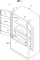
- FIG. 1 is a perspective view of a refrigerator according to an embodiment of the present disclosure.
- a refrigerator 1 may include a body 10 and a storage compartment 20 provided in the body 10 and having an open front surface so that items may be placed therein and withdrawn therefrom.
- the refrigerator 1 may include a door 30 rotatably coupled to the body 10 to open and close the open front surface of the storage compartment 20, and a cool air supply device configured to supply cool air to the storage compartment 20.
- the body 10 may include an outer case 11 and an inner case 12.
- the outer case 11 may form an exterior of the body 10.
- the outer case 11 may be formed of a metal material having excellent durability and aesthetics.
- the inner case 12 may be located on an inner side of the outer case 11.
- the inner case 12 may form an exterior of the storage compartment 20.
- the inner case 12 may be integrally injection-molded with a plastic material.
- the storage compartment 20 may be partitioned into a plurality of storage compartments 20 by a partition wall 13.
- the storage compartment 20 may include an upper storage compartment 20a and a lower storage compartment 20b.
- Each of the upper storage compartment 20a and the lower storage compartment 20b may be partitioned into a left storage compartment and a right storage compartment by another partition wall (not shown).
- the storage compartment 20 may include a refrigerator compartment and a freezer compartment.
- the upper storage compartment 20a may be provided as a refrigerating compartment and the lower storage compartment 20b may be provided as a freezing compartment, and conversely, the upper storage compartment 20a may be provided as a freezing compartment and the lower storage compartment 20b may be provided as a refrigerating compartment.
- the refrigerator 1 shown in FIG. 1 is a bottom freezer type refrigerator in which the upper storage compartment 20a is provided as a refrigerating compartment and the lower storage compartment 20b is provided as a freezing compartment.
- the refrigerator of the present disclosure is not limited thereto, and other types of refrigerators may be applied thereto as long as a storage box 100 may be mounted in the storage compartment 20 such as a refrigerator compartment or a freezer compartment.
- refrigerators include a side-by-side type refrigerator in which a freezer compartment and a refrigerator compartment are disposed in a lateral direction, and a top mounting type refrigerator in which a freezer compartment is disposed on a refrigerator compartment.
- the freezer compartment and the refrigerator compartment may be maintained at about -20 °C and about 3 °C, respectively.
- the freezer compartment and the refrigerator compartment may be insulated by the partition wall 13.
- the storage compartment 20 may be opened or closed by the door 30.
- the upper storage compartment 20a may be opened or closed by a pair of upper doors 30a rotatably coupled to the body 10.
- the lower storage compartment 20b may be opened or closed by a drawer type lower door 30b slidably coupled to the body 10.
- the present disclosure is not limited thereto, and the door 30 may be variously provided as long as the storage compartment 20 may be opened and closed.
- a plurality of door guards 31 capable of accommodating items and the like may be provided.
- the door guard 31 may be provided to accommodate small volume items or the like.
- the storage compartment 20 may be provided with shelves 40 capable of supporting items stored in the storage compartment 20.
- the plurality of shelves 40 may be provided.
- the shelves 40 may be installed anywhere in the refrigerator compartment or the freezer compartment.
- the shelves 40 vertically disposed to be spaced apart from each other partition the inside of the storage compartment 20 into multiple stages, and thereby utilization efficiency of a storage space can be increased and items to be stored can be easily accommodated on the shelves 40.
- the shelves 40 may be provided such that a position thereof is movable other than the position thereof being fixed.
- the drawer type storage box 100 configured to store vegetables, fruits, or the like may be disposed inside the storage compartment 20.
- the storage box 100 may be provided to store items in a closed internal space thereof. A detailed structure of the storage box 100 will be described below.
- FIG. 2 is a side cross-sectional view of the refrigerator according to the embodiment of the present disclosure.
- an insulator 60 may be foamed between the inner and outer cases 12 and 11 to prevent an outflow of cool air from the storage compartment 20.
- the cool air supply device may supply cool air to the storage compartment 20.
- the refrigerator 1 includes components for a freezing cycle therein.
- the refrigerator 1 may refrigerate or freeze items stored in the storage compartment 20 via cool air generated by the components for the freezing cycle.
- a cool air circulation path 70 may be formed in the rear of the storage compartment 20.
- An evaporator 71 configured to cool the storage compartment 20 may be installed in the cool air circulation path 70.
- a cool air circulating fan 72 configured to circulate air inside the storage compartment 20 may be installed above the evaporator 71 in the cool air circulation path 70.
- a panel 50 configured to partition the cool air circulation path 70 and the storage compartment 20 may be installed in front of the evaporator 71.
- the panel 50 may be provided with a cool air discharger 51 for discharging cool air guided through the cool air circulation path into the storage compartment 20.
- the cool air circulating fan 72 may blow air passing through the evaporator 71 into the cool air circulation path 70.
- a machine room 80 partitioned from the storage compartment 20 may be provided in a lower portion of the body 10.
- a compressor 81 configured to compress a refrigerant, a condenser (not shown) configured to condense the compressed refrigerant, a refrigerant expansion device (not shown) configured to expand the compressed refrigerant, and the like may be installed in the machine room 80.
- a cooling principle of the refrigerator 1 is as follows.
- a refrigerant gas contained in the refrigerator 1 is compressed by the compressor 81 into a high-temperature and highpressure gas, and is sent to a condenser (not shown) to release heat such that the refrigerant gas may be condensed and liquefied.
- the liquefied refrigerant is in a state of being easily vaporized at a low temperature while being depressurized in a capillary tube, and the liquefied refrigerant may then be vaporized again in a low temperature evaporator 71, and heat of air surrounding the capillary tube may be transferred to the refrigerant and a temperature of the air may drop.
- the cool air that is the air with the lowered temperature, is discharged into the storage compartment 20 of the refrigerator 1, and a refrigeration or freezing function may be performed.
- the vaporized refrigerant gas is sent back to the compressor 81, and the above-described process may be repeated, and such a cooling method is referred to as a gas compression type cooling method. Further, since this method is efficient and has excellent cooling power, it may be widely used in a general household.
- FIG. 3 is a perspective view of a storage box in the refrigerator according to the embodiment of the present disclosure.
- the refrigerator 1 may include the storage box 100 installed to be withdrawable in the storage compartment 20 and a cover 110 rotatably provided above the storage box.
- a gap G may exist between the cover 110 and the storage box 100. Cool air in the storage compartment 20 may flow into the storage box 100 through the gap G such that humidity inside the storage box 100 is affected.
- the gap G between the storage box 100 and the cover 110 will be described in detail below.
- the refrigerator 1 may include cover shelves 170 capable of performing a function of a plurality of shelves 40 capable of accommodating items stored in the storage compartment 20, and partitioning the accommodation space of the storage box 100.
- the storage box 100 may be slidably withdrawn in a frontward direction by a roller or the like.
- the refrigerator 1 may include a knob 130 interlocked with the cover 110 so that a user can rotate the cover 110 to adjust the humidity inside the storage box 100.
- knob 130 is illustrated as being mounted on the cover shelve 170, the knob 130 is not limited thereto, and the knob 130 may be disposed in various places with various shapes as long as the user may operate and rotate the cover 110.
- a knob 130a included in the refrigerator 1 according to a first embodiment and a knob 130b included in the refrigerator 1 according to a second embodiment are shown on one cover shelf 170, but the present disclosure is not limited thereto.
- the refrigerator 1 according to the embodiments of the present disclosure may be configured to include various types of storage boxes 100 including the refrigerator 1 according to the first embodiment and the refrigerator 1 according to the second embodiment.
- FIG. 4 is a view showing hook coupling of a cover frame and a cover in the refrigerator according to the embodiment of the present disclosure.
- the refrigerator 1 according to the embodiment of the present disclosure may include a cover frame 120 for supporting the cover 110.
- the cover frame 120 may include a hook 121 configured to be hook-coupled with the cover 110, and the hook 121 may be located on a rear surface of the cover frame 120.
- the hook 121 may be provided at a rear end portion of the cover frame 120.
- the hook 121 may have a hook shape shown in FIG. 4 , but is not limited thereto, and the hook 121 may have various shapes as long as it may be hook-coupled to the cover 110.
- the cover 110 may include a pin 111 positioned on the rear surface of the cover 110 to be coupled to the hook 121.
- the pin 111 may have a " " shape and an opening so that the hook 121 may be coupled thereto.
- the pin 111 may have various shapes as long as the pin 111 may be hook-coupled to the hook 121.
- the cover 110 may be rotated in a vertical direction to selectively close the inside of the storage box 100.
- the cover 110 may be rotated in the vertical direction with respect to a rotation axis in which the hook 121 and the pin 111 are hook-coupled to each other.
- a radius by which the cover 110 may be rotated may be limited in an upward direction by the cover frame 120 and may be limited in a downward direction by the storage box 100. Accordingly, the cover 110 may actually rotate by a fine angle in the vertical direction.
- the cover 110 is hook-coupled to the cover frame 120 and is rotated upward and downward to adjust humidity inside the storage box 100.
- FIG. 4 two hooks 121 and two pins 111 are formed, and each of the hook 121 and the pin 111 are positioned at rear end portions of the cover frame 120 and the cover 110, but the present disclosure is not limited thereto.
- various numbers of hooks 121 and pins 111 may be provided at various positions as long as the cover 110 may be rotated via the hook 121 and the pin 111 being hook-coupled.
- FIG. 5 is an exploded view of main components of the refrigerator according to the first embodiment of the present disclosure. As shown in FIG. 5 , the cover 110 may be disposed above the storage box 100, and the cover frame 120 may be disposed above the cover 110.
- the cover shelves 170 may be disposed above the cover frame 120 and may include a glass shelf 171 made of a glass material and a metal shelf 172 made of a metal material.
- the glass shelf 171 may be fitted into and engaged with the cover frame 120, and the metal shelf 172 may be positioned above the glass shelf 171 and engaged with the cover frame 120 to cover the cover frame 120.
- the refrigerator 1 may include the knob 130a installed on the cover frame 120 and an adjusting member 140 connected to the knob 130a.
- the refrigerator 1 may include an adjusting trim 150 to which the adjusting member 140 may be fixed.
- a detailed structure of the adjusting member 140 and the adjusting trim 150 will be described below.
- the knob 130a may have a knob shape so that a user may easily grasp the knob 130a and may pass through the cover frame 120 and the metal shelf 172. Accordingly, the cover frame 120 and the metal shelf 172 may include holes to allow the knob 130a to pass therethrough.
- the adjusting member 140 may have a " " shape.
- the cover 110 included in the refrigerator 1 according to the first embodiment may be configured to be rotated in the vertical direction in conjunction with the knob 130a sliding in one direction.
- the cover 110 may have a space in which the adjusting member 140 and the adjusting trim 150 may be received to be coupled with the adjusting member 140 and the cover frame 120 to which the adjusting trim 150 is coupled.
- FIG. 6 is an exploded view of main components constituting a rear surface of the cover frame in the refrigerator according to the first embodiment of the present disclosure.
- the cover frame 120 may include a guide groove 122 provided in the rear surface of the cover frame 120.
- the guide groove 122 may have a " " shape similar to the shape of the adjusting member 140.
- the adjusting member 140 is inserted into the guide groove 122 and may be connected to and guided by the knob 130a configured to be slid in one direction.
- the adjusting member 140 is inserted into the guide groove 122, and the adjusting trim 150 is coupled with the guide groove 122 to fix the adjusting member 140 in the guide groove 122.
- a coupling structure of the adjusting trim 150 and the guide groove 122 may be variously formed, and, for example, the adjusting trim 150 may be fitted into and coupled with the guide groove 122 or the like.
- One end of the metal shelf 172 may be bent to be coupled with the cover frame 120 while protecting the glass shelf 171.
- the cover frame 120 may include cam guides 123 connected to the guide groove 122.
- the cam guides 123 may guide movement of cams 112 which will be described below. A detailed structure of the cam 112 and the cam guide 123 will be described below.
- FIG. 7 is a view showing a state before the cover is rotated upward by the knob in the refrigerator according to the first embodiment of the present disclosure.
- FIG. 8 is a view showing a state after the cover is rotated upward by the knob in the refrigerator according to the first embodiment of the present disclosure.
- the adjusting member 140 includes a first adjusting member 141 connected to the knob 130a and second adjusting members 142 bent and extending from both ends of the first adjusting member 141.
- the cover 110 includes the cams 112 protruding from both sides thereof, and the adjusting member 140 may move the cam 112 in the vertical direction.
- the second adjusting member 142 may include an inclined portion 143 provided so that the cam 112 may be moved in the vertical direction. Accordingly, before the adjusting member 140 is slid, the cam 112 may be in contact with a lowest portion of the inclined portion 143.
- the cam 112 When the adjusting member 140 is slid, the cam 112 may be moved upward along an inclination of the inclined portion 143, and a highest portion of the inclined portion 143 may come into contact with the cam 112.
- the first adjusting member 141 connected to the knob 130a by being slid in a lateral direction of the knob 130a may be moved in the same direction as a sliding direction of the knob 130a
- the second adjusting member 142 may be moved in forward and backward directions in conjunction with movement of the first adjusting member 141 along the guide groove 122.
- the cam 112 may be moved in the vertical direction along the inclined portion 143 by the forward and backward movement of the second adjusting member 142.
- the cover 110 may be rotated to have the gap G with the storage box 100 as a rotation axis of the hook 121 and the pin 111.
- the plurality of second adjusting members 142 are provided, and the inclined portions 143 thereof may have different shapes so that the second adjusting members 142 simultaneously move the cams 112. That is, since the adjusting member 140 slides in one direction together with the sliding of the knob 130a, lengths of the plurality of second adjusting members 142 and positions of the inclined portions 143 may be different from each other.
- the adjusting member 140 is moved in a state in which the adjusting member 140 is inserted into the guide groove 122 so that movement of the adjusting member 140 due to the sliding of the knob 130a may be restricted.
- a range of the movement of the adjusting member 140 may correspond to a range in which the cam 112 may move in the vertical direction within the cam guide 123.
- FIG. 9 is a view showing a gap between the cover and the storage box according to the embodiment of the present disclosure. As shown in FIG. 9 , the cover 110 selectively closes the storage box 100 so that the humidity inside the storage box 100 may be adjusted.
- the cam 112 may be guided by the cam guide 123 provided on the cover frame 120. That is, the cam 112 moved by the adjusting member 140 is guided along the cam guide 123, and the movement of the cam 112 may be restricted by the cam guide 123.
- the cam guide 123 may be connected to the guide groove 122.
- the gap G between the storage box 100 and the cover 110 is very small and may be brought into a substantially closed state, and thus high humidity may be maintained inside the storage box 100. Accordingly, freshness of food inside the storage box 100 may be maintained.
- the gap G between the storage box 100 and the cover 110 becomes relatively large in a state in which the cover 110 is rotated upward, and thus relatively low humidity may be maintained inside the storage box 100.
- the humidity inside the storage box 100 may be appropriately adjusted according to items stored in the storage box 100.
- FIG. 10 is an exploded view of main components of the refrigerator according to the second embodiment of the present disclosure. As shown in FIG. 10 , the refrigerator 1 according to the second embodiment differs from the refrigerator 1 according to the first embodiment in a configuration of the knob 130b, and most of the other main components are the same.
- the knob 130b may be disposed to pass through the cover shelf 170 and the cover 110. Accordingly, the metal shelf 172, the glass shelf 171, and the cover 110 may include circular holes through which the knob 130b may pass.
- the knob 130b may be operated separately from the cover frame 120.
- the cover 110 included in the refrigerator 1 according to the second embodiment may be configured to be connected to the rotating knob 130b so that the cover 110 may be rotated in the vertical direction. Therefore, the gap G between the cover 110 and the storage box 100 may be formed.
- the refrigerator 1 according to the second embodiment may include a screw member 160 connected to the rotating knob 130b, configured to perform a spiral motion, and passing through the cover 110.
- the glass shelf 171 and the cover 110 may include a coupling member for interlocking with the screw member 160.
- the screw member 160 may pass through the opening of the cover frame 120.
- FIG. 11 is a view showing a state before the cover is rotated upward by the knob in the refrigerator according to the second embodiment of the present disclosure.
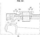
- FIG. 12 is a view showing a state after the cover is rotated upward by the knob in the refrigerator according to the second embodiment of the present disclosure.
- the screw member 160 included in the refrigerator 1 according to the second embodiment may include a first screw member 161 in contact with the cover shelf 170, and a second screw member 162 extending from the first screw member 161.
- the second screw member 162 may include a spiral portion 163 in contact with the cover 110.
- the cover 110 may be configured to rotate in the vertical direction due to the spiral portion 163 configured to perform a spiral motion.
- the knob 130b may be rotated at a fixed position.
- the screw member 160 may also perform spiral motion together with the knob 130b.
- the cover shelf 170 and the first screw member 161 do not interfere with each other in spite of the spiral motion of the first screw member 161, the first screw member may perform the spiral motion without interfering with the cover shelf 170 connected to the first screw member.
- the cover 110 and the spiral portion 163 connected to the second screw member 162 may interfere with the second screw member 162.
- the cover 110 which interferes with the spiral portion 163 due to the spiral motion of the second screw member 162, may be moved in the vertical direction.
- the cover 110 may have the gap G with the storage box 100 due to the spiral motion of the second screw member 162.
- the upward and downward movement of the cover 110 may be limited by a length of the spiral portion 163.
- the downward movement of the cover 110 may be limited by a lower end of the spiral portion 163, and the upward movement of the cover 110 may be limited by an upper end of the spiral portion 163.
- the cover 110 may be moved within a range of the second screw member 162 including the spiral portion 163.
- the refrigerator 1 may include various embodiments in addition to the first embodiment and the second embodiment.
- a refrigerator (not shown) according to a third embodiment may include knobs (not shown) arranged on both sides of an adjusting member (not shown) and a cover frame (not shown).
- the adjusting member may include first adjusting members (not shown) connected to the knobs (not shown), and second adjusting members (not shown) bent and extending from one ends of the first adjusting members (not shown) and provided to move cams (not shown).
- the plurality of knobs (not shown), first adjusting members (not shown), and second adjusting members (not shown) may be provided, and the number thereof may preferably be two.
- inclined portions (not shown) of the second adjusting members (not shown) may have the same shape and length for each second adjusting member (not shown).
- the plurality of knobs (not shown) may form a coupling relationship with each other so that one knob (not shown) may be slid in conjunction with movement of the other knob (not shown).
- a refrigerator (not shown) according to a fourth embodiment may include a knob (not shown), an adjusting member (not shown), and a screw member (not shown).
- the screw member (not shown) may perform a spiral motion in conjunction with the rotating knob (not shown).
- the adjusting member (not shown) may be configured to move a cover (not shown) in a vertical direction by being connected to the screw member (not shown). That is, the refrigerator (not shown) according to the fourth embodiment may include the adjusting member (not shown) corresponding to the adjusting member 140 of the refrigerator 1 according to the first embodiment, and the knob (not shown) and the screw member respectively corresponding to the knob 130b and the screw member 160 of the refrigerator 1 according to the second embodiment.
- a refrigerator can maintain quality of food stored therein by keeping a storage box closed and maintaining humidity of an inside of the storage box at a high level.
- the refrigerator according to the embodiments of the present disclosure can maintain freshness of food stored therein according the type of stored food by having a simple structure that can adjust humidity inside the storage box through movement of the cover when it is necessary for the humidity inside the storage box to be kept at a low level.
Landscapes
- Engineering & Computer Science (AREA)
- Chemical & Material Sciences (AREA)
- Combustion & Propulsion (AREA)
- Physics & Mathematics (AREA)
- Mechanical Engineering (AREA)
- Thermal Sciences (AREA)
- General Engineering & Computer Science (AREA)
- Cold Air Circulating Systems And Constructional Details In Refrigerators (AREA)
- Refrigerator Housings (AREA)
- Devices That Are Associated With Refrigeration Equipment (AREA)
Abstract
Description
- The present disclosure relates to a refrigerator, and more particularly, to a refrigerator having a storage box configured to adjust humidity in a storage compartment.
- A refrigerator is a household appliance capable of maintaining freshness of the food by including a storage compartment capable of storing food and a cool air supply device configured to supply cool air to the storage compartment.
- A temperature of the storage compartment is maintained at a temperature within a certain range required to keep the food fresh. A storage compartment of such a refrigerator is provided with an open front surface, and the open front surface is normally closed by a door to maintain a temperature of the storage compartment.
- A plurality of shelves for partitioning the storage compartment into a plurality of storage compartments and a plurality of storage boxes capable of storing items, such as food, therein are provided inside the storage compartment.
- An upper portion of a storage box is in an open shape, and a cover is provided on an upper side of the storage box to close the open shape.
- A gap between the storage box and the cover may be large, and thus air inside the storage box may flow into the storage compartment or cool air in the storage compartment may be excessively introduced into the storage box, thereby affecting humidity inside the storage box.
- Thus, a cover is generally provided so as not to move so that a small gap may be maintained between the storage box and the cover so that the storage box is substantially sealed by the cover.
- However, although the humidity inside the storage box may be maintained by such a cover and high humidity may be maintained by closing the storage box, there is a case in which a sealing function is not required, that is, in which it is necessary to maintain the humidity inside the storage box at a low level to maintain a low humidity state inside the storage box.
- Thus, it may be necessary to adjust the humidity inside the storage box depending on the nature of items stored in the storage box.
- Therefore, it is an aspect of the present disclosure to provide a refrigerator including an improved storage box such that the storage box may be sealed to maintain high humidity inside the storage box.
- It is another aspect of the present disclosure to provide a refrigerator including an improved storage box that has a simple structure capable of adjusting humidity therein by moving a cover when it is necessary to maintain the humidity inside the storage box needs at a low level.
- Additional aspects of the disclosure will be set forth in part in the description which follows and, in part, will be obvious from the description, or may be learned by practice of the disclosure.
- In accordance with one aspect of the present disclosure, a refrigerator is provided, the refrigerator including a body having a storage compartment, a storage box installed to be drawable in the storage compartment, a cover located above the storage box and provided to be rotatable, a cover frame configured to support the cover, and a knob configured to rotate the cover to adjust humidity inside the storage box.
- The cover frame may include a hook configured to be hook-coupled with the cover.
- The cover may include a pin coupled to the hook and located on a rear surface of the cover.
- The cover may be configured to have a gap with the storage box in conjunction with the knob sliding in one direction.
- The cover frame may include a guide groove provided in a rear surface of the cover frame and further include an adjusting member inserted into the guide groove and configured to be engaged with the knob sliding in one direction.
- The cover may include cams protruding from both sides thereof, and the adjusting member may be provided at a lower portion of the cam to move the cam.
- The adjusting member may include a first adjusting member connected to the knob and second adjusting members bent and extending from both ends of the first adjusting member.
- The second adjusting member may include an inclined portion configured to come into contact with the cam to move the cam in a vertical direction.
- The plurality of second adjusting members may be provided, and the inclined portions thereof may have different shapes so that the second adjusting members simultaneously move the cams.
- The adjusting member may include first adjusting members connected to knobs disposed on both sides of the cover frame and second adjusting members bent and extending from one end portions of the first adjusting members to move the cams.
- The cover may be configured to have a gap with the storage box in conjunction with the rotating knob.
- The refrigerator may further include a screw member connected to the rotating knob, configured to perform a spiral motion, and passing through the cover.
- The refrigerator may further include a cover shelf located above the cover frame and configured to accommodate an item stored in the storage compartment, wherein the screw member may include a first screw member configured to pass through the cover shelf to come into contact with the cover shelf.
- The screw member may further include a second screw member extending from the first screw member, and the second screw member may include a spiral portion in contact with the cover.
- The cover may be engaged with the second screw member configured to perform a spiral motion and have a gap with the storage box.
- The refrigerator may further include a screw member connected to the rotating knob and configured to perform a spiral motion, and an adjusting member configured to move the cover in a vertical direction in conjunction with the screw member. In accordance with another aspect of the present disclosure, a refrigerator is provided, the refrigerator including a storage box, a cover located above the storage box and provided to be rotatable in a vertical direction to selectively close an inside of the storage box, a knob configured to adjust rotation of the cover in the vertical direction to adjust humidity inside the storage box, and an adjusting member configured to engage the knob with the cover to control rotation of the cover in the vertical direction by the knob being slid in the lateral direction.
- The adjusting member may include a first adjusting member connected to the knob and second adjusting members bent and extending from both sides of the first adjusting member and configured to move the cover in the vertical direction.
- In accordance with still another aspect of the present disclosure, a refrigerator is provided, the refrigerator including a storage box, a cover located above the storage box and provided to be movable in a vertical direction to selectively close an inside of the storage box, a knob configured to adjust movement of the cover in the vertical direction to adjust the humidity inside the storage box, and a screw member configured to engage the knob with the cover to control rotation of the cover in the vertical direction by the knob being rotated.
- The screw member may perform a spiral motion due to rotation of the knob and include a spiral portion provided to move the cover in the vertical direction.
- These and/or other aspects of the disclosure will become apparent and more readily appreciated from the following description of the embodiments, taken in conjunction with the accompanying drawings of which:
-
FIG. 1 is a perspective view of a refrigerator according to an embodiment of the present disclosure; -
FIG. 2 is a side cross-sectional view of the refrigerator according to the embodiment of the present disclosure; -
FIG. 3 is a perspective view of a storage box in the refrigerator according to the embodiment of the present disclosure; -
FIG. 4 is a view showing hook coupling of a cover frame and a cover in the refrigerator according to the embodiment of the present disclosure; -
FIG. 5 is an exploded view of main components of a refrigerator according to a first embodiment of the present disclosure; -
FIG. 6 is an exploded view of main components constituting a rear surface of a cover frame in the refrigerator according to the first embodiment of the present disclosure; -
FIG. 7 is a view showing a state before the cover is rotated upward by a knob in the refrigerator according to the first embodiment of the present disclosure; -
FIG. 8 is a view showing a state after the cover is rotated upward by the knob in the refrigerator according to the first embodiment of the present disclosure; -
FIG. 9 is a view showing a gap between the cover and the storage box according to the embodiment of the present disclosure; -
FIG. 10 is an exploded view of main components of a refrigerator according to a second embodiment of the present disclosure; -
FIG. 11 is a view showing a state before a cover is rotated upward by a knob in the refrigerator according to the second embodiment of the present disclosure; and -
FIG. 12 is a view showing a state after the cover is rotated upward by the knob in the refrigerator according to the second embodiment of the present disclosure. - Embodiments described in this specification and configurations illustrated in the accompanying drawings are only exemplary examples of the disclosure. It should be understood that the disclosure covers various modifications that may substitute for the embodiments herein and drawings at the time of filing of this application.
- Further, identical reference numbers or symbols given in the accompanying drawings of the present specification indicate substantially the same components or components that perform substantially the same function. Further, terms used in the present specification are used only to describe exemplary embodiments and are not intended to limit and/or restrict disclosed disclosure.
- An expression used in the singular encompasses an expression of the plural unless it has a clearly different meaning in the context. In the present specification, it should be understood that terms such as "including," "having," and "comprising" are intended to indicate the existence of the features, numbers, steps, actions, components, parts, or combinations thereof disclosed in the specification.
- Accordingly, it is not intended to preclude the possibility that one or more other features, numbers, steps, actions, components, parts, or combinations thereof may exist or be added.
- It should be understood that, although the terms "first," "second," and the like used in the present specification are used to describe various elements, the elements are not limited by the terms. The terms are only used to distinguish one element from another.
- For example, a first element could be termed a second element, and, similarly, a second element could be termed a first element without departing from the scope of the present disclosure. As used herein, the term "and/or" includes any and all combinations of one or more of the associated listed items.
- In addition, the terms "front side," "rear side," "upper side," and "lower side used in the present specification are defined with reference to the drawings, but the shape and position of each component are not limited thereby.
- Hereinafter, a refrigerator according to an embodiment of the present disclosure will be described in detail with reference to the accompanying drawings.
-
FIG. 1 is a perspective view of a refrigerator according to an embodiment of the present disclosure. As shown inFIG. 1 , arefrigerator 1 may include abody 10 and astorage compartment 20 provided in thebody 10 and having an open front surface so that items may be placed therein and withdrawn therefrom. - The
refrigerator 1 may include adoor 30 rotatably coupled to thebody 10 to open and close the open front surface of thestorage compartment 20, and a cool air supply device configured to supply cool air to thestorage compartment 20. - The
body 10 may include anouter case 11 and aninner case 12. Theouter case 11 may form an exterior of thebody 10. Theouter case 11 may be formed of a metal material having excellent durability and aesthetics. - The
inner case 12 may be located on an inner side of theouter case 11. Theinner case 12 may form an exterior of thestorage compartment 20. Theinner case 12 may be integrally injection-molded with a plastic material. - The
storage compartment 20 may be partitioned into a plurality ofstorage compartments 20 by apartition wall 13. Thestorage compartment 20 may include anupper storage compartment 20a and alower storage compartment 20b. Each of theupper storage compartment 20a and thelower storage compartment 20b may be partitioned into a left storage compartment and a right storage compartment by another partition wall (not shown). - The
storage compartment 20 may include a refrigerator compartment and a freezer compartment. Depending on the type of refrigerator, theupper storage compartment 20a may be provided as a refrigerating compartment and thelower storage compartment 20b may be provided as a freezing compartment, and conversely, theupper storage compartment 20a may be provided as a freezing compartment and thelower storage compartment 20b may be provided as a refrigerating compartment. - The
refrigerator 1 shown inFIG. 1 is a bottom freezer type refrigerator in which theupper storage compartment 20a is provided as a refrigerating compartment and thelower storage compartment 20b is provided as a freezing compartment. - However, the refrigerator of the present disclosure is not limited thereto, and other types of refrigerators may be applied thereto as long as a
storage box 100 may be mounted in thestorage compartment 20 such as a refrigerator compartment or a freezer compartment. - Other types of refrigerators include a side-by-side type refrigerator in which a freezer compartment and a refrigerator compartment are disposed in a lateral direction, and a top mounting type refrigerator in which a freezer compartment is disposed on a refrigerator compartment.
- The freezer compartment and the refrigerator compartment may be maintained at about -20 °C and about 3 °C, respectively. The freezer compartment and the refrigerator compartment may be insulated by the
partition wall 13. - The
storage compartment 20 may be opened or closed by thedoor 30. Theupper storage compartment 20a may be opened or closed by a pair ofupper doors 30a rotatably coupled to thebody 10. Thelower storage compartment 20b may be opened or closed by a drawer typelower door 30b slidably coupled to thebody 10. - However, the present disclosure is not limited thereto, and the
door 30 may be variously provided as long as thestorage compartment 20 may be opened and closed. - On a rear surface of the
upper door 30a, a plurality ofdoor guards 31 capable of accommodating items and the like may be provided. Thedoor guard 31 may be provided to accommodate small volume items or the like. - The
storage compartment 20 may be provided withshelves 40 capable of supporting items stored in thestorage compartment 20. The plurality ofshelves 40 may be provided. Theshelves 40 may be installed anywhere in the refrigerator compartment or the freezer compartment. - The
shelves 40 vertically disposed to be spaced apart from each other partition the inside of thestorage compartment 20 into multiple stages, and thereby utilization efficiency of a storage space can be increased and items to be stored can be easily accommodated on theshelves 40. - Recently, as the refrigerator has become larger, items located deep on a rear side of the
shelf 40 may not be easily withdrawn. Accordingly, theshelves 40 may be provided such that a position thereof is movable other than the position thereof being fixed. - The drawer
type storage box 100 configured to store vegetables, fruits, or the like may be disposed inside thestorage compartment 20. Thestorage box 100 may be provided to store items in a closed internal space thereof. A detailed structure of thestorage box 100 will be described below. -
FIG. 2 is a side cross-sectional view of the refrigerator according to the embodiment of the present disclosure. As shown inFIG. 2 , aninsulator 60 may be foamed between the inner andouter cases storage compartment 20. - The cool air supply device may supply cool air to the
storage compartment 20. Generally, therefrigerator 1 includes components for a freezing cycle therein. Therefrigerator 1 may refrigerate or freeze items stored in thestorage compartment 20 via cool air generated by the components for the freezing cycle. - A cool
air circulation path 70 may be formed in the rear of thestorage compartment 20. An evaporator 71 configured to cool thestorage compartment 20 may be installed in the coolair circulation path 70. - A cool
air circulating fan 72 configured to circulate air inside thestorage compartment 20 may be installed above theevaporator 71 in the coolair circulation path 70. Apanel 50 configured to partition the coolair circulation path 70 and thestorage compartment 20 may be installed in front of theevaporator 71. - The
panel 50 may be provided with acool air discharger 51 for discharging cool air guided through the cool air circulation path into thestorage compartment 20. The coolair circulating fan 72 may blow air passing through theevaporator 71 into the coolair circulation path 70. - A
machine room 80 partitioned from thestorage compartment 20 may be provided in a lower portion of thebody 10. Acompressor 81 configured to compress a refrigerant, a condenser (not shown) configured to condense the compressed refrigerant, a refrigerant expansion device (not shown) configured to expand the compressed refrigerant, and the like may be installed in themachine room 80. - A cooling principle of the
refrigerator 1 is as follows. A refrigerant gas contained in therefrigerator 1 is compressed by thecompressor 81 into a high-temperature and highpressure gas, and is sent to a condenser (not shown) to release heat such that the refrigerant gas may be condensed and liquefied. - The liquefied refrigerant is in a state of being easily vaporized at a low temperature while being depressurized in a capillary tube, and the liquefied refrigerant may then be vaporized again in a
low temperature evaporator 71, and heat of air surrounding the capillary tube may be transferred to the refrigerant and a temperature of the air may drop. - The cool air, that is the air with the lowered temperature, is discharged into the
storage compartment 20 of therefrigerator 1, and a refrigeration or freezing function may be performed. - The vaporized refrigerant gas is sent back to the
compressor 81, and the above-described process may be repeated, and such a cooling method is referred to as a gas compression type cooling method. Further, since this method is efficient and has excellent cooling power, it may be widely used in a general household. -
FIG. 3 is a perspective view of a storage box in the refrigerator according to the embodiment of the present disclosure. As shown inFIG. 3 , therefrigerator 1 according to the embodiment of the present disclosure may include thestorage box 100 installed to be withdrawable in thestorage compartment 20 and acover 110 rotatably provided above the storage box. - A gap G may exist between the
cover 110 and thestorage box 100. Cool air in thestorage compartment 20 may flow into thestorage box 100 through the gap G such that humidity inside thestorage box 100 is affected. - The gap G between the
storage box 100 and thecover 110 will be described in detail below. - The
refrigerator 1 according to the embodiment of the present disclosure may includecover shelves 170 capable of performing a function of a plurality ofshelves 40 capable of accommodating items stored in thestorage compartment 20, and partitioning the accommodation space of thestorage box 100. Thestorage box 100 may be slidably withdrawn in a frontward direction by a roller or the like. - The
refrigerator 1 according to the embodiment of the present disclosure may include aknob 130 interlocked with thecover 110 so that a user can rotate thecover 110 to adjust the humidity inside thestorage box 100. - In
FIG. 3 , although theknob 130 is illustrated as being mounted on the cover shelve 170, theknob 130 is not limited thereto, and theknob 130 may be disposed in various places with various shapes as long as the user may operate and rotate thecover 110. - In
FIG. 3 , aknob 130a included in therefrigerator 1 according to a first embodiment and aknob 130b included in therefrigerator 1 according to a second embodiment are shown on onecover shelf 170, but the present disclosure is not limited thereto. - Accordingly, the
refrigerator 1 according to the embodiments of the present disclosure may be configured to include various types ofstorage boxes 100 including therefrigerator 1 according to the first embodiment and therefrigerator 1 according to the second embodiment. -
FIG. 4 is a view showing hook coupling of a cover frame and a cover in the refrigerator according to the embodiment of the present disclosure. As shown inFIG 4 , therefrigerator 1 according to the embodiment of the present disclosure may include acover frame 120 for supporting thecover 110. - The
cover frame 120 may include ahook 121 configured to be hook-coupled with thecover 110, and thehook 121 may be located on a rear surface of thecover frame 120. Thehook 121 may be provided at a rear end portion of thecover frame 120. - The
hook 121 may have a hook shape shown inFIG. 4 , but is not limited thereto, and thehook 121 may have various shapes as long as it may be hook-coupled to thecover 110. - The
cover 110 may include apin 111 positioned on the rear surface of thecover 110 to be coupled to thehook 121. Thepin 111 may have a " " shape and an opening so that thehook 121 may be coupled thereto. - However, the present disclosure is not limited thereto, and the
pin 111 may have various shapes as long as thepin 111 may be hook-coupled to thehook 121. - By the
hook 121 and thepin 111 being hook-coupled, thecover 110 may be rotated in a vertical direction to selectively close the inside of thestorage box 100. - That is, the
cover 110 may be rotated in the vertical direction with respect to a rotation axis in which thehook 121 and thepin 111 are hook-coupled to each other. A radius by which thecover 110 may be rotated may be limited in an upward direction by thecover frame 120 and may be limited in a downward direction by thestorage box 100. Accordingly, thecover 110 may actually rotate by a fine angle in the vertical direction. - The
cover 110 is hook-coupled to thecover frame 120 and is rotated upward and downward to adjust humidity inside thestorage box 100. - In
FIG. 4 , twohooks 121 and twopins 111 are formed, and each of thehook 121 and thepin 111 are positioned at rear end portions of thecover frame 120 and thecover 110, but the present disclosure is not limited thereto. - Accordingly, various numbers of
hooks 121 and pins 111 may be provided at various positions as long as thecover 110 may be rotated via thehook 121 and thepin 111 being hook-coupled. - Hereinafter, embodiments of the
refrigerator 1 according to the present disclosure will be mainly described -
FIG. 5 is an exploded view of main components of the refrigerator according to the first embodiment of the present disclosure. As shown inFIG. 5 , thecover 110 may be disposed above thestorage box 100, and thecover frame 120 may be disposed above thecover 110. - The
cover shelves 170 may be disposed above thecover frame 120 and may include aglass shelf 171 made of a glass material and ametal shelf 172 made of a metal material. - The
glass shelf 171 may be fitted into and engaged with thecover frame 120, and themetal shelf 172 may be positioned above theglass shelf 171 and engaged with thecover frame 120 to cover thecover frame 120. - The
refrigerator 1 according to the first embodiment of the present disclosure may include theknob 130a installed on thecover frame 120 and an adjustingmember 140 connected to theknob 130a. - The
refrigerator 1 according to the first embodiment may include an adjustingtrim 150 to which the adjustingmember 140 may be fixed. A detailed structure of the adjustingmember 140 and the adjustingtrim 150 will be described below. - The
knob 130a may have a knob shape so that a user may easily grasp theknob 130a and may pass through thecover frame 120 and themetal shelf 172. Accordingly, thecover frame 120 and themetal shelf 172 may include holes to allow theknob 130a to pass therethrough. - The adjusting
member 140 may have a " " shape. Thecover 110 included in therefrigerator 1 according to the first embodiment may be configured to be rotated in the vertical direction in conjunction with theknob 130a sliding in one direction. - The
cover 110 may have a space in which the adjustingmember 140 and the adjustingtrim 150 may be received to be coupled with the adjustingmember 140 and thecover frame 120 to which the adjustingtrim 150 is coupled. -
FIG. 6 is an exploded view of main components constituting a rear surface of the cover frame in the refrigerator according to the first embodiment of the present disclosure. As shown inFIG. 6 , thecover frame 120 may include aguide groove 122 provided in the rear surface of thecover frame 120. - The
guide groove 122 may have a " " shape similar to the shape of the adjustingmember 140. The adjustingmember 140 is inserted into theguide groove 122 and may be connected to and guided by theknob 130a configured to be slid in one direction. - The adjusting
member 140 is inserted into theguide groove 122, and the adjustingtrim 150 is coupled with theguide groove 122 to fix the adjustingmember 140 in theguide groove 122. - A coupling structure of the adjusting
trim 150 and theguide groove 122 may be variously formed, and, for example, the adjustingtrim 150 may be fitted into and coupled with theguide groove 122 or the like. - One end of the
metal shelf 172 may be bent to be coupled with thecover frame 120 while protecting theglass shelf 171. - The
cover frame 120 may include cam guides 123 connected to theguide groove 122. The cam guides 123 may guide movement ofcams 112 which will be described below. A detailed structure of thecam 112 and thecam guide 123 will be described below. -
FIG. 7 is a view showing a state before the cover is rotated upward by the knob in the refrigerator according to the first embodiment of the present disclosure.FIG. 8 is a view showing a state after the cover is rotated upward by the knob in the refrigerator according to the first embodiment of the present disclosure. - As shown in
FIGS. 7 and8 , the adjustingmember 140 includes afirst adjusting member 141 connected to theknob 130a and second adjustingmembers 142 bent and extending from both ends of the first adjustingmember 141. - The
cover 110 includes thecams 112 protruding from both sides thereof, and the adjustingmember 140 may move thecam 112 in the vertical direction. - The
second adjusting member 142 may include aninclined portion 143 provided so that thecam 112 may be moved in the vertical direction. Accordingly, before the adjustingmember 140 is slid, thecam 112 may be in contact with a lowest portion of theinclined portion 143. - When the adjusting
member 140 is slid, thecam 112 may be moved upward along an inclination of theinclined portion 143, and a highest portion of theinclined portion 143 may come into contact with thecam 112. - Accordingly, the first adjusting
member 141 connected to theknob 130a by being slid in a lateral direction of theknob 130a may be moved in the same direction as a sliding direction of theknob 130a - The
second adjusting member 142 may be moved in forward and backward directions in conjunction with movement of the first adjustingmember 141 along theguide groove 122. Thecam 112 may be moved in the vertical direction along theinclined portion 143 by the forward and backward movement of thesecond adjusting member 142. - By the
cam 112 being moved in the vertical direction, thecover 110 may be rotated to have the gap G with thestorage box 100 as a rotation axis of thehook 121 and thepin 111. - The plurality of second adjusting
members 142 are provided, and theinclined portions 143 thereof may have different shapes so that thesecond adjusting members 142 simultaneously move thecams 112. That is, since the adjustingmember 140 slides in one direction together with the sliding of theknob 130a, lengths of the plurality of second adjustingmembers 142 and positions of theinclined portions 143 may be different from each other. - The adjusting
member 140 is moved in a state in which the adjustingmember 140 is inserted into theguide groove 122 so that movement of the adjustingmember 140 due to the sliding of theknob 130a may be restricted. - That is, a range of the movement of the adjusting
member 140 may correspond to a range in which thecam 112 may move in the vertical direction within thecam guide 123. -
FIG. 9 is a view showing a gap between the cover and the storage box according to the embodiment of the present disclosure. As shown inFIG. 9 , thecover 110 selectively closes thestorage box 100 so that the humidity inside thestorage box 100 may be adjusted. - The
cam 112 may be guided by thecam guide 123 provided on thecover frame 120. That is, thecam 112 moved by the adjustingmember 140 is guided along thecam guide 123, and the movement of thecam 112 may be restricted by thecam guide 123. Thecam guide 123 may be connected to theguide groove 122. - In a state in which the
cover 110 is not rotated upward, the gap G between thestorage box 100 and thecover 110 is very small and may be brought into a substantially closed state, and thus high humidity may be maintained inside thestorage box 100. Accordingly, freshness of food inside thestorage box 100 may be maintained. - On the other hand, the gap G between the
storage box 100 and thecover 110 becomes relatively large in a state in which thecover 110 is rotated upward, and thus relatively low humidity may be maintained inside thestorage box 100. - Accordingly, by the
cover 110 being rotated, the humidity inside thestorage box 100 may be appropriately adjusted according to items stored in thestorage box 100. -
FIG. 10 is an exploded view of main components of the refrigerator according to the second embodiment of the present disclosure. As shown inFIG. 10 , therefrigerator 1 according to the second embodiment differs from therefrigerator 1 according to the first embodiment in a configuration of theknob 130b, and most of the other main components are the same. - The
knob 130b may be disposed to pass through thecover shelf 170 and thecover 110. Accordingly, themetal shelf 172, theglass shelf 171, and thecover 110 may include circular holes through which theknob 130b may pass. - The
knob 130b may be operated separately from thecover frame 120. Thecover 110 included in therefrigerator 1 according to the second embodiment may be configured to be connected to therotating knob 130b so that thecover 110 may be rotated in the vertical direction. Therefore, the gap G between thecover 110 and thestorage box 100 may be formed. - The
refrigerator 1 according to the second embodiment may include ascrew member 160 connected to therotating knob 130b, configured to perform a spiral motion, and passing through thecover 110. - The
glass shelf 171 and thecover 110 may include a coupling member for interlocking with thescrew member 160. Thescrew member 160 may pass through the opening of thecover frame 120. -
FIG. 11 is a view showing a state before the cover is rotated upward by the knob in the refrigerator according to the second embodiment of the present disclosure.FIG. 12 is a view showing a state after the cover is rotated upward by the knob in the refrigerator according to the second embodiment of the present disclosure. - As shown in
FIGS. 11 and12 , thescrew member 160 included in therefrigerator 1 according to the second embodiment may include afirst screw member 161 in contact with thecover shelf 170, and asecond screw member 162 extending from thefirst screw member 161. - The
second screw member 162 may include aspiral portion 163 in contact with thecover 110. Thecover 110 may be configured to rotate in the vertical direction due to thespiral portion 163 configured to perform a spiral motion. Theknob 130b may be rotated at a fixed position. - That is, when the
knob 130b is rotated, thescrew member 160 may also perform spiral motion together with theknob 130b. However, since thecover shelf 170 and thefirst screw member 161 do not interfere with each other in spite of the spiral motion of thefirst screw member 161, the first screw member may perform the spiral motion without interfering with thecover shelf 170 connected to the first screw member. - On the other hand, the
cover 110 and thespiral portion 163 connected to thesecond screw member 162 may interfere with thesecond screw member 162. Thecover 110, which interferes with thespiral portion 163 due to the spiral motion of thesecond screw member 162, may be moved in the vertical direction. - Accordingly, the
cover 110 may have the gap G with thestorage box 100 due to the spiral motion of thesecond screw member 162. - The upward and downward movement of the
cover 110 may be limited by a length of thespiral portion 163. The downward movement of thecover 110 may be limited by a lower end of thespiral portion 163, and the upward movement of thecover 110 may be limited by an upper end of thespiral portion 163. - That is, the
cover 110 may be moved within a range of thesecond screw member 162 including thespiral portion 163. - Although not shown in the drawings, the
refrigerator 1 according to the embodiments of the present disclosure may include various embodiments in addition to the first embodiment and the second embodiment. - For example, a refrigerator (not shown) according to a third embodiment may include knobs (not shown) arranged on both sides of an adjusting member (not shown) and a cover frame (not shown).
- The adjusting member (not shown) may include first adjusting members (not shown) connected to the knobs (not shown), and second adjusting members (not shown) bent and extending from one ends of the first adjusting members (not shown) and provided to move cams (not shown).
- That is, the plurality of knobs (not shown), first adjusting members (not shown), and second adjusting members (not shown) may be provided, and the number thereof may preferably be two.
- According to the third embodiment, inclined portions (not shown) of the second adjusting members (not shown) may have the same shape and length for each second adjusting member (not shown). Meanwhile, the plurality of knobs (not shown) may form a coupling relationship with each other so that one knob (not shown) may be slid in conjunction with movement of the other knob (not shown).
- Also, a refrigerator (not shown) according to a fourth embodiment may include a knob (not shown), an adjusting member (not shown), and a screw member (not shown). The screw member (not shown) may perform a spiral motion in conjunction with the rotating knob (not shown).
- The adjusting member (not shown) may be configured to move a cover (not shown) in a vertical direction by being connected to the screw member (not shown). That is, the refrigerator (not shown) according to the fourth embodiment may include the adjusting member (not shown) corresponding to the adjusting
member 140 of therefrigerator 1 according to the first embodiment, and the knob (not shown) and the screw member respectively corresponding to theknob 130b and thescrew member 160 of therefrigerator 1 according to the second embodiment. - As is apparent from the above description, a refrigerator according to the embodiments of the present disclosure can maintain quality of food stored therein by keeping a storage box closed and maintaining humidity of an inside of the storage box at a high level.
- Further, the refrigerator according to the embodiments of the present disclosure can maintain freshness of food stored therein according the type of stored food by having a simple structure that can adjust humidity inside the storage box through movement of the cover when it is necessary for the humidity inside the storage box to be kept at a low level.
- Although the technical scope of the present invention has been described above with reference to the specific embodiments, the scope of the present invention is not limited to the embodiments. Although a few embodiments of the present invention have been shown and described, it should be appreciated by those skilled in the art that changes may be made in these embodiments without departing from the principles of the invention, the scope of which is defined in the claims.
Claims (15)
- A refrigerator comprising:a body having a storage compartment;a storage box installed to be drawable in the storage compartment;a cover located above the storage box and provided to be rotatable;a cover frame configured to support the cover; anda knob configured to rotate the cover to adjust humidity inside the storage box.
- The refrigerator of claim 1, wherein the cover frame includes a hook configured to be hook-coupled with the cover.
- The refrigerator of claim 2, wherein the cover includes a pin coupled to the hook and located on a rear surface of the cover.
- The refrigerator of claim 1, 2 or 3, wherein the cover is configured to have a gap with the storage box in conjunction with the knob sliding in one direction.
- The refrigerator of any one of the preceding claims, wherein the cover frame includes a guide groove provided in a rear surface of the cover frame, and further comprising an adjusting member inserted into the guide groove and configured to be engaged with the knob sliding in one direction.
- The refrigerator of claim 5, wherein the cover includes cams protruding from both sides thereof, and the adjusting member is provided at a lower portion of the cam to move the cam.
- The refrigerator of claim 5 or 6, wherein the adjusting member includes a first adjusting member connected to the knob and second adjusting members bent and extending from both ends of the first adjusting member.
- The refrigerator of claim 7, wherein the second adjusting member includes an inclined portion configured to come into contact with the cam to move the cam in a vertical direction.
- The refrigerator of claim 8, wherein the plurality of second adjusting members are provided, and the inclined portions thereof have different shapes so that the second adjusting members simultaneously move the cams.
- The refrigerator of claim 6, wherein the adjusting member includes first adjusting members connected to knobs disposed on both sides of the cover frame and second adjusting members bent and extending from one end portions of the first adjusting members to move the cams.
- The refrigerator of any one of the preceding claims, wherein the cover is configured to have a gap with the storage box in conjunction with the rotating knob.
- The refrigerator of any one of the preceding claims, further comprising a screw member connected to the rotating knob, configured to perform a spiral motion, and passing through the cover.
- The refrigerator of claim 12, further comprising a cover shelf located above the cover frame and configured to accommodate an item stored in the storage compartment,
wherein the screw member includes a first screw member configured to pass through the cover shelf to come into contact with the cover shelf. - The refrigerator of claim 13, wherein the screw member further includes a second screw member extending from the first screw member, and the second screw member includes a spiral portion in contact with the cover.
- The refrigerator of claim 14, wherein the cover is engaged with the second screw member configured to perform a spiral motion and has a gap with the storage box.
Applications Claiming Priority (1)
| Application Number | Priority Date | Filing Date | Title |
|---|---|---|---|
| KR1020170000950A KR102718829B1 (en) | 2017-01-03 | 2017-01-03 | Refrigerator |
Publications (2)
| Publication Number | Publication Date |
|---|---|
| EP3343156A1 true EP3343156A1 (en) | 2018-07-04 |
| EP3343156B1 EP3343156B1 (en) | 2021-08-18 |
Family
ID=60782048
Family Applications (1)
| Application Number | Title | Priority Date | Filing Date |
|---|---|---|---|
| EP17210031.5A Active EP3343156B1 (en) | 2017-01-03 | 2017-12-22 | Refrigerator |
Country Status (4)
| Country | Link |
|---|---|
| US (1) | US10962281B2 (en) |
| EP (1) | EP3343156B1 (en) |
| KR (1) | KR102718829B1 (en) |
| CN (1) | CN108266948B (en) |
Cited By (4)
| Publication number | Priority date | Publication date | Assignee | Title |
|---|---|---|---|---|
| CN109084522A (en) * | 2018-08-21 | 2018-12-25 | 海信(山东)冰箱有限公司 | Push type adjustable knob structure and the adjustable refrigerator drawer of dry and wet |
| CN113915838A (en) * | 2021-09-27 | 2022-01-11 | 海信(山东)冰箱有限公司 | A kind of refrigerator |
| EP4086546A1 (en) * | 2021-05-03 | 2022-11-09 | BSH Hausgeräte GmbH | Domestic refrigerator and food storage container with an air-conditioning device with a specific adjustment between a shell and an attachment |
| EP4509784A4 (en) * | 2022-09-13 | 2025-07-30 | Samsung Electronics Co Ltd | Refrigerator |
Families Citing this family (16)
| Publication number | Priority date | Publication date | Assignee | Title |
|---|---|---|---|---|
| DE102017216189A1 (en) * | 2017-09-13 | 2019-03-14 | BSH Hausgeräte GmbH | Domestic refrigeration appliance with specific front lowering of a shelf |
| CN109405403A (en) * | 2018-08-30 | 2019-03-01 | 安徽康佳同创电器有限公司 | A kind of wind cooling refrigerator automatically adjusting storage box humidity and its control method |
| CN109764615B (en) * | 2018-12-27 | 2021-03-23 | 海尔智家股份有限公司 | Covers, drawer assemblies and refrigerators |
| CN109708370B (en) * | 2018-12-28 | 2024-01-12 | 长虹美菱股份有限公司 | A refrigerator with a simple humidity control device |
| CN112146342B (en) * | 2019-06-28 | 2022-03-04 | 青岛海尔电冰箱有限公司 | Storage devices and refrigerators |
| EP3772625B1 (en) | 2019-08-05 | 2023-10-04 | Whirlpool Corporation | Refrigerator |
| KR20210136367A (en) | 2020-05-07 | 2021-11-17 | 삼성전자주식회사 | Refrigerator |
| KR102532799B1 (en) * | 2020-07-01 | 2023-05-16 | 엘지전자 주식회사 | Refregerator |
| KR20220121083A (en) * | 2021-02-24 | 2022-08-31 | 삼성전자주식회사 | refrigerator |
| CN115077153A (en) * | 2021-03-10 | 2022-09-20 | 博西华电器(江苏)有限公司 | Refrigeration device |
| CN115247926A (en) * | 2021-04-28 | 2022-10-28 | 博西华电器(江苏)有限公司 | Refrigerator and method for adjusting cover of drawer in refrigerating chamber |
| CN115247925A (en) * | 2021-04-28 | 2022-10-28 | 博西华电器(江苏)有限公司 | Refrigerator and method for adjusting cover of drawer in refrigerating chamber |
| DE102021204415A1 (en) * | 2021-05-03 | 2022-11-03 | BSH Hausgeräte GmbH | Food storage container with an air conditioning device with a specific adjustment part between a tray and a top, and household refrigeration appliance |
| EP4227615B1 (en) | 2021-05-14 | 2026-04-01 | Samsung Electronics Co., Ltd. | Refrigerator |
| TR2021020751A1 (en) * | 2021-12-23 | 2023-07-21 | Bsh Ev Aletleri Sanayi Ve Ticaret Anonim Sirketi | A COOLING DEVICE HAVING A HUMIDITY CONTROLLED CONTAINER |
| KR20240036415A (en) * | 2022-09-13 | 2024-03-20 | 삼성전자주식회사 | Refrigerator |
Citations (5)
| Publication number | Priority date | Publication date | Assignee | Title |
|---|---|---|---|---|
| WO2004038311A1 (en) * | 2002-10-23 | 2004-05-06 | Lg Electronics Inc. | Vegetable room for refrigerator |
| KR20090133008A (en) * | 2008-06-23 | 2009-12-31 | 엘지전자 주식회사 | Refrigerator with adjusting member |
| DE102009029141A1 (en) * | 2009-09-02 | 2011-03-03 | BSH Bosch und Siemens Hausgeräte GmbH | Refrigerating appliance with vegetable compartment |
| DE102012221496A1 (en) * | 2012-11-23 | 2014-05-28 | BSH Bosch und Siemens Hausgeräte GmbH | Domestic refrigerating appliance with an actuating means for a container lid |
| WO2015082279A1 (en) * | 2013-12-06 | 2015-06-11 | BSH Hausgeräte GmbH | Domestic refrigeration appliance having a keep-fresh container that is located in an interior and has a cover which can be raised and lowered by way of an operating element in a drawer |
Family Cites Families (7)
| Publication number | Priority date | Publication date | Assignee | Title |
|---|---|---|---|---|
| US4250719A (en) | 1979-09-04 | 1981-02-17 | General Electric Company | Household refrigerator humidity controlled pan assembly |
| KR100524785B1 (en) | 2002-10-23 | 2005-10-31 | 엘지전자 주식회사 | Vegetable room optimum preservation apparatus for refrigerator |
| KR100833356B1 (en) | 2006-05-10 | 2008-05-28 | 엘지전자 주식회사 | Automatic opening structure of storage container of refrigerator |
| KR101072755B1 (en) | 2009-02-19 | 2011-10-11 | 엘지전자 주식회사 | Refrigerator and control method thereof |
| DE102009029139A1 (en) | 2009-09-02 | 2011-03-03 | BSH Bosch und Siemens Hausgeräte GmbH | Refrigerating appliance with vegetable compartment |
| KR20130116741A (en) * | 2012-04-16 | 2013-10-24 | 엘지전자 주식회사 | A sealing structure for a vegetables container of a refrigerator |
| DE102012221499A1 (en) * | 2012-11-23 | 2014-05-28 | BSH Bosch und Siemens Hausgeräte GmbH | Domestic refrigerating appliance with a display means for a container lid |
-
2017
- 2017-01-03 KR KR1020170000950A patent/KR102718829B1/en active Active
- 2017-12-22 EP EP17210031.5A patent/EP3343156B1/en active Active
-
2018
- 2018-01-02 US US15/860,496 patent/US10962281B2/en active Active
- 2018-01-03 CN CN201810004695.9A patent/CN108266948B/en not_active Expired - Fee Related
Patent Citations (5)
| Publication number | Priority date | Publication date | Assignee | Title |
|---|---|---|---|---|
| WO2004038311A1 (en) * | 2002-10-23 | 2004-05-06 | Lg Electronics Inc. | Vegetable room for refrigerator |
| KR20090133008A (en) * | 2008-06-23 | 2009-12-31 | 엘지전자 주식회사 | Refrigerator with adjusting member |
| DE102009029141A1 (en) * | 2009-09-02 | 2011-03-03 | BSH Bosch und Siemens Hausgeräte GmbH | Refrigerating appliance with vegetable compartment |
| DE102012221496A1 (en) * | 2012-11-23 | 2014-05-28 | BSH Bosch und Siemens Hausgeräte GmbH | Domestic refrigerating appliance with an actuating means for a container lid |
| WO2015082279A1 (en) * | 2013-12-06 | 2015-06-11 | BSH Hausgeräte GmbH | Domestic refrigeration appliance having a keep-fresh container that is located in an interior and has a cover which can be raised and lowered by way of an operating element in a drawer |
Cited By (4)
| Publication number | Priority date | Publication date | Assignee | Title |
|---|---|---|---|---|
| CN109084522A (en) * | 2018-08-21 | 2018-12-25 | 海信(山东)冰箱有限公司 | Push type adjustable knob structure and the adjustable refrigerator drawer of dry and wet |
| EP4086546A1 (en) * | 2021-05-03 | 2022-11-09 | BSH Hausgeräte GmbH | Domestic refrigerator and food storage container with an air-conditioning device with a specific adjustment between a shell and an attachment |
| CN113915838A (en) * | 2021-09-27 | 2022-01-11 | 海信(山东)冰箱有限公司 | A kind of refrigerator |
| EP4509784A4 (en) * | 2022-09-13 | 2025-07-30 | Samsung Electronics Co Ltd | Refrigerator |
Also Published As
| Publication number | Publication date |
|---|---|
| KR102718829B1 (en) | 2024-10-18 |
| US20180187966A1 (en) | 2018-07-05 |
| CN108266948B (en) | 2020-11-17 |
| EP3343156B1 (en) | 2021-08-18 |
| KR20180080053A (en) | 2018-07-11 |
| US10962281B2 (en) | 2021-03-30 |
| CN108266948A (en) | 2018-07-10 |
Similar Documents
| Publication | Publication Date | Title |
|---|---|---|
| EP3343156B1 (en) | Refrigerator | |
| RU2491484C1 (en) | Refrigerator | |
| KR101716033B1 (en) | A refrigerator and a method controlling the same | |
| KR101554852B1 (en) | Refrigerator | |
| US9534833B2 (en) | Basket for refrigerator | |
| KR101650386B1 (en) | Refrigerator and Evaporator for Refrigerator | |
| CN111721048B (en) | Refrigerator with a door | |
| KR101700501B1 (en) | A refrigerator and a method controlling the same | |
| KR101810736B1 (en) | A refrigerator and a method controlling the same | |
| EP2594878B1 (en) | Refrigerator | |
| EP3217126B1 (en) | Refrigerator | |
| KR20180062122A (en) | Refrigerator | |
| JP5481311B2 (en) | refrigerator | |
| US20180087828A1 (en) | Refrigerator | |
| KR20060129664A (en) | Refrigerator | |
| KR101638191B1 (en) | Refrigerator | |
| KR20170116868A (en) | Refrigerator and drawer guide assembly thereof | |
| US11306964B2 (en) | Refrigerator | |
| KR20170060318A (en) | Refrigerator | |
| EP4509784A1 (en) | Refrigerator | |
| KR100614316B1 (en) | Refrigerator | |
| KR20240036415A (en) | Refrigerator | |
| KR20060103571A (en) | Refrigerator | |
| JP2017026207A (en) | refrigerator | |
| KR20100096784A (en) | A refrigerator |
Legal Events
| Date | Code | Title | Description |
|---|---|---|---|
| PUAI | Public reference made under article 153(3) epc to a published international application that has entered the european phase |
Free format text: ORIGINAL CODE: 0009012 |
|
| STAA | Information on the status of an ep patent application or granted ep patent |
Free format text: STATUS: REQUEST FOR EXAMINATION WAS MADE |
|
| 17P | Request for examination filed |
Effective date: 20171222 |
|
| AK | Designated contracting states |
Kind code of ref document: A1 Designated state(s): AL AT BE BG CH CY CZ DE DK EE ES FI FR GB GR HR HU IE IS IT LI LT LU LV MC MK MT NL NO PL PT RO RS SE SI SK SM TR |
|
| AX | Request for extension of the european patent |
Extension state: BA ME |
|
| STAA | Information on the status of an ep patent application or granted ep patent |
Free format text: STATUS: EXAMINATION IS IN PROGRESS |
|
| 17Q | First examination report despatched |
Effective date: 20191002 |
|
| GRAP | Despatch of communication of intention to grant a patent |
Free format text: ORIGINAL CODE: EPIDOSNIGR1 |
|
| STAA | Information on the status of an ep patent application or granted ep patent |
Free format text: STATUS: GRANT OF PATENT IS INTENDED |
|
| INTG | Intention to grant announced |
Effective date: 20210329 |
|
| GRAS | Grant fee paid |
Free format text: ORIGINAL CODE: EPIDOSNIGR3 |
|
| GRAA | (expected) grant |
Free format text: ORIGINAL CODE: 0009210 |
|
| STAA | Information on the status of an ep patent application or granted ep patent |
Free format text: STATUS: THE PATENT HAS BEEN GRANTED |
|
| AK | Designated contracting states |
Kind code of ref document: B1 Designated state(s): AL AT BE BG CH CY CZ DE DK EE ES FI FR GB GR HR HU IE IS IT LI LT LU LV MC MK MT NL NO PL PT RO RS SE SI SK SM TR |
|
| REG | Reference to a national code |
Ref country code: GB Ref legal event code: FG4D |
|
| REG | Reference to a national code |
Ref country code: CH Ref legal event code: EP |
|
| REG | Reference to a national code |
Ref country code: DE Ref legal event code: R096 Ref document number: 602017044205 Country of ref document: DE |
|
| REG | Reference to a national code |
Ref country code: IE Ref legal event code: FG4D Ref country code: AT Ref legal event code: REF Ref document number: 1421993 Country of ref document: AT Kind code of ref document: T Effective date: 20210915 |
|
| REG | Reference to a national code |
Ref country code: LT Ref legal event code: MG9D |
|
| REG | Reference to a national code |
Ref country code: NL Ref legal event code: MP Effective date: 20210818 |
|
| REG | Reference to a national code |
Ref country code: AT Ref legal event code: MK05 Ref document number: 1421993 Country of ref document: AT Kind code of ref document: T Effective date: 20210818 |
|
| PG25 | Lapsed in a contracting state [announced via postgrant information from national office to epo] |
Ref country code: PT Free format text: LAPSE BECAUSE OF FAILURE TO SUBMIT A TRANSLATION OF THE DESCRIPTION OR TO PAY THE FEE WITHIN THE PRESCRIBED TIME-LIMIT Effective date: 20211220 Ref country code: NO Free format text: LAPSE BECAUSE OF FAILURE TO SUBMIT A TRANSLATION OF THE DESCRIPTION OR TO PAY THE FEE WITHIN THE PRESCRIBED TIME-LIMIT Effective date: 20211118 Ref country code: ES Free format text: LAPSE BECAUSE OF FAILURE TO SUBMIT A TRANSLATION OF THE DESCRIPTION OR TO PAY THE FEE WITHIN THE PRESCRIBED TIME-LIMIT Effective date: 20210818 Ref country code: FI Free format text: LAPSE BECAUSE OF FAILURE TO SUBMIT A TRANSLATION OF THE DESCRIPTION OR TO PAY THE FEE WITHIN THE PRESCRIBED TIME-LIMIT Effective date: 20210818 Ref country code: AT Free format text: LAPSE BECAUSE OF FAILURE TO SUBMIT A TRANSLATION OF THE DESCRIPTION OR TO PAY THE FEE WITHIN THE PRESCRIBED TIME-LIMIT Effective date: 20210818 Ref country code: BG Free format text: LAPSE BECAUSE OF FAILURE TO SUBMIT A TRANSLATION OF THE DESCRIPTION OR TO PAY THE FEE WITHIN THE PRESCRIBED TIME-LIMIT Effective date: 20211118 Ref country code: LT Free format text: LAPSE BECAUSE OF FAILURE TO SUBMIT A TRANSLATION OF THE DESCRIPTION OR TO PAY THE FEE WITHIN THE PRESCRIBED TIME-LIMIT Effective date: 20210818 Ref country code: SE Free format text: LAPSE BECAUSE OF FAILURE TO SUBMIT A TRANSLATION OF THE DESCRIPTION OR TO PAY THE FEE WITHIN THE PRESCRIBED TIME-LIMIT Effective date: 20210818 Ref country code: RS Free format text: LAPSE BECAUSE OF FAILURE TO SUBMIT A TRANSLATION OF THE DESCRIPTION OR TO PAY THE FEE WITHIN THE PRESCRIBED TIME-LIMIT Effective date: 20210818 Ref country code: HR Free format text: LAPSE BECAUSE OF FAILURE TO SUBMIT A TRANSLATION OF THE DESCRIPTION OR TO PAY THE FEE WITHIN THE PRESCRIBED TIME-LIMIT Effective date: 20210818 |
|
| PGFP | Annual fee paid to national office [announced via postgrant information from national office to epo] |
Ref country code: FR Payment date: 20211125 Year of fee payment: 5 |
|
| PG25 | Lapsed in a contracting state [announced via postgrant information from national office to epo] |
Ref country code: PL Free format text: LAPSE BECAUSE OF FAILURE TO SUBMIT A TRANSLATION OF THE DESCRIPTION OR TO PAY THE FEE WITHIN THE PRESCRIBED TIME-LIMIT Effective date: 20210818 Ref country code: LV Free format text: LAPSE BECAUSE OF FAILURE TO SUBMIT A TRANSLATION OF THE DESCRIPTION OR TO PAY THE FEE WITHIN THE PRESCRIBED TIME-LIMIT Effective date: 20210818 Ref country code: GR Free format text: LAPSE BECAUSE OF FAILURE TO SUBMIT A TRANSLATION OF THE DESCRIPTION OR TO PAY THE FEE WITHIN THE PRESCRIBED TIME-LIMIT Effective date: 20211119 |
|
| PG25 | Lapsed in a contracting state [announced via postgrant information from national office to epo] |
Ref country code: NL Free format text: LAPSE BECAUSE OF FAILURE TO SUBMIT A TRANSLATION OF THE DESCRIPTION OR TO PAY THE FEE WITHIN THE PRESCRIBED TIME-LIMIT Effective date: 20210818 |
|
| PG25 | Lapsed in a contracting state [announced via postgrant information from national office to epo] |
Ref country code: DK Free format text: LAPSE BECAUSE OF FAILURE TO SUBMIT A TRANSLATION OF THE DESCRIPTION OR TO PAY THE FEE WITHIN THE PRESCRIBED TIME-LIMIT Effective date: 20210818 |
|
| REG | Reference to a national code |
Ref country code: DE Ref legal event code: R097 Ref document number: 602017044205 Country of ref document: DE |
|
| PG25 | Lapsed in a contracting state [announced via postgrant information from national office to epo] |
Ref country code: SM Free format text: LAPSE BECAUSE OF FAILURE TO SUBMIT A TRANSLATION OF THE DESCRIPTION OR TO PAY THE FEE WITHIN THE PRESCRIBED TIME-LIMIT Effective date: 20210818 Ref country code: SK Free format text: LAPSE BECAUSE OF FAILURE TO SUBMIT A TRANSLATION OF THE DESCRIPTION OR TO PAY THE FEE WITHIN THE PRESCRIBED TIME-LIMIT Effective date: 20210818 Ref country code: RO Free format text: LAPSE BECAUSE OF FAILURE TO SUBMIT A TRANSLATION OF THE DESCRIPTION OR TO PAY THE FEE WITHIN THE PRESCRIBED TIME-LIMIT Effective date: 20210818 Ref country code: EE Free format text: LAPSE BECAUSE OF FAILURE TO SUBMIT A TRANSLATION OF THE DESCRIPTION OR TO PAY THE FEE WITHIN THE PRESCRIBED TIME-LIMIT Effective date: 20210818 Ref country code: CZ Free format text: LAPSE BECAUSE OF FAILURE TO SUBMIT A TRANSLATION OF THE DESCRIPTION OR TO PAY THE FEE WITHIN THE PRESCRIBED TIME-LIMIT Effective date: 20210818 Ref country code: AL Free format text: LAPSE BECAUSE OF FAILURE TO SUBMIT A TRANSLATION OF THE DESCRIPTION OR TO PAY THE FEE WITHIN THE PRESCRIBED TIME-LIMIT Effective date: 20210818 |
|
| PLBE | No opposition filed within time limit |
Free format text: ORIGINAL CODE: 0009261 |
|
| STAA | Information on the status of an ep patent application or granted ep patent |
Free format text: STATUS: NO OPPOSITION FILED WITHIN TIME LIMIT |
|
| 26N | No opposition filed |
Effective date: 20220519 |
|
| PG25 | Lapsed in a contracting state [announced via postgrant information from national office to epo] |
Ref country code: MC Free format text: LAPSE BECAUSE OF FAILURE TO SUBMIT A TRANSLATION OF THE DESCRIPTION OR TO PAY THE FEE WITHIN THE PRESCRIBED TIME-LIMIT Effective date: 20210818 Ref country code: IT Free format text: LAPSE BECAUSE OF FAILURE TO SUBMIT A TRANSLATION OF THE DESCRIPTION OR TO PAY THE FEE WITHIN THE PRESCRIBED TIME-LIMIT Effective date: 20210818 |
|
| REG | Reference to a national code |
Ref country code: CH Ref legal event code: PL |
|
| GBPC | Gb: european patent ceased through non-payment of renewal fee |
Effective date: 20211222 |
|
| PG25 | Lapsed in a contracting state [announced via postgrant information from national office to epo] |
Ref country code: SI Free format text: LAPSE BECAUSE OF FAILURE TO SUBMIT A TRANSLATION OF THE DESCRIPTION OR TO PAY THE FEE WITHIN THE PRESCRIBED TIME-LIMIT Effective date: 20210818 |
|
| REG | Reference to a national code |
Ref country code: BE Ref legal event code: MM Effective date: 20211231 |
|
| PG25 | Lapsed in a contracting state [announced via postgrant information from national office to epo] |
Ref country code: LU Free format text: LAPSE BECAUSE OF NON-PAYMENT OF DUE FEES Effective date: 20211222 Ref country code: IE Free format text: LAPSE BECAUSE OF NON-PAYMENT OF DUE FEES Effective date: 20211222 Ref country code: GB Free format text: LAPSE BECAUSE OF NON-PAYMENT OF DUE FEES Effective date: 20211222 |
|
| PG25 | Lapsed in a contracting state [announced via postgrant information from national office to epo] |
Ref country code: BE Free format text: LAPSE BECAUSE OF NON-PAYMENT OF DUE FEES Effective date: 20211231 |
|
| PG25 | Lapsed in a contracting state [announced via postgrant information from national office to epo] |
Ref country code: LI Free format text: LAPSE BECAUSE OF NON-PAYMENT OF DUE FEES Effective date: 20211231 Ref country code: CH Free format text: LAPSE BECAUSE OF NON-PAYMENT OF DUE FEES Effective date: 20211231 |
|
| PG25 | Lapsed in a contracting state [announced via postgrant information from national office to epo] |
Ref country code: HU Free format text: LAPSE BECAUSE OF FAILURE TO SUBMIT A TRANSLATION OF THE DESCRIPTION OR TO PAY THE FEE WITHIN THE PRESCRIBED TIME-LIMIT; INVALID AB INITIO Effective date: 20171222 |
|
| PG25 | Lapsed in a contracting state [announced via postgrant information from national office to epo] |
Ref country code: CY Free format text: LAPSE BECAUSE OF FAILURE TO SUBMIT A TRANSLATION OF THE DESCRIPTION OR TO PAY THE FEE WITHIN THE PRESCRIBED TIME-LIMIT Effective date: 20210818 |
|
| PG25 | Lapsed in a contracting state [announced via postgrant information from national office to epo] |
Ref country code: FR Free format text: LAPSE BECAUSE OF NON-PAYMENT OF DUE FEES Effective date: 20221231 |
|
| PG25 | Lapsed in a contracting state [announced via postgrant information from national office to epo] |
Ref country code: MK Free format text: LAPSE BECAUSE OF FAILURE TO SUBMIT A TRANSLATION OF THE DESCRIPTION OR TO PAY THE FEE WITHIN THE PRESCRIBED TIME-LIMIT Effective date: 20210818 |
|
| PG25 | Lapsed in a contracting state [announced via postgrant information from national office to epo] |
Ref country code: TR Free format text: LAPSE BECAUSE OF FAILURE TO SUBMIT A TRANSLATION OF THE DESCRIPTION OR TO PAY THE FEE WITHIN THE PRESCRIBED TIME-LIMIT Effective date: 20210818 |
|
| PG25 | Lapsed in a contracting state [announced via postgrant information from national office to epo] |
Ref country code: MT Free format text: LAPSE BECAUSE OF FAILURE TO SUBMIT A TRANSLATION OF THE DESCRIPTION OR TO PAY THE FEE WITHIN THE PRESCRIBED TIME-LIMIT Effective date: 20210818 |
|
| PGFP | Annual fee paid to national office [announced via postgrant information from national office to epo] |
Ref country code: DE Payment date: 20251120 Year of fee payment: 9 |