EP3345233B1 - Système de gestion de batterie et connecteur de puissance - Google Patents
Système de gestion de batterie et connecteur de puissance Download PDFInfo
- Publication number
- EP3345233B1 EP3345233B1 EP16745027.9A EP16745027A EP3345233B1 EP 3345233 B1 EP3345233 B1 EP 3345233B1 EP 16745027 A EP16745027 A EP 16745027A EP 3345233 B1 EP3345233 B1 EP 3345233B1
- Authority
- EP
- European Patent Office
- Prior art keywords
- terminal
- face
- disposed
- channel
- current shunt
- Prior art date
- Legal status (The legal status is an assumption and is not a legal conclusion. Google has not performed a legal analysis and makes no representation as to the accuracy of the status listed.)
- Active
Links
Images


Classifications
-
- H—ELECTRICITY
- H01—ELECTRIC ELEMENTS
- H01R—ELECTRICALLY-CONDUCTIVE CONNECTIONS; STRUCTURAL ASSOCIATIONS OF A PLURALITY OF MUTUALLY-INSULATED ELECTRICAL CONNECTING ELEMENTS; COUPLING DEVICES; CURRENT COLLECTORS
- H01R13/00—Details of coupling devices of the kinds covered by groups H01R12/70 or H01R24/00 - H01R33/00
- H01R13/66—Structural association with built-in electrical component
- H01R13/68—Structural association with built-in electrical component with built-in fuse
- H01R13/684—Structural association with built-in electrical component with built-in fuse the fuse being removable
-
- H—ELECTRICITY
- H01—ELECTRIC ELEMENTS
- H01M—PROCESSES OR MEANS, e.g. BATTERIES, FOR THE DIRECT CONVERSION OF CHEMICAL ENERGY INTO ELECTRICAL ENERGY
- H01M50/00—Constructional details or processes of manufacture of the non-active parts of electrochemical cells other than fuel cells, e.g. hybrid cells
- H01M50/50—Current conducting connections for cells or batteries
- H01M50/572—Means for preventing undesired use or discharge
- H01M50/574—Devices or arrangements for the interruption of current
- H01M50/583—Devices or arrangements for the interruption of current in response to current, e.g. fuses
-
- H—ELECTRICITY
- H01—ELECTRIC ELEMENTS
- H01R—ELECTRICALLY-CONDUCTIVE CONNECTIONS; STRUCTURAL ASSOCIATIONS OF A PLURALITY OF MUTUALLY-INSULATED ELECTRICAL CONNECTING ELEMENTS; COUPLING DEVICES; CURRENT COLLECTORS
- H01R13/00—Details of coupling devices of the kinds covered by groups H01R12/70 or H01R24/00 - H01R33/00
- H01R13/66—Structural association with built-in electrical component
- H01R13/6608—Structural association with built-in electrical component with built-in single component
- H01R13/6616—Structural association with built-in electrical component with built-in single component with resistor
-
- H—ELECTRICITY
- H02—GENERATION; CONVERSION OR DISTRIBUTION OF ELECTRIC POWER
- H02J—ELECTRIC POWER NETWORKS; CIRCUIT ARRANGEMENTS OR SYSTEMS FOR SUPPLYING OR DISTRIBUTING ELECTRIC POWER; SYSTEMS FOR STORING ELECTRIC ENERGY
- H02J7/00—Circuit arrangements for charging or discharging batteries or for supplying loads from batteries
- H02J7/60—Circuit arrangements for charging or discharging batteries or for supplying loads from batteries including safety or protection arrangements
- H02J7/663—Circuit arrangements for charging or discharging batteries or for supplying loads from batteries including safety or protection arrangements using battery or load disconnect circuits
-
- H—ELECTRICITY
- H02—GENERATION; CONVERSION OR DISTRIBUTION OF ELECTRIC POWER
- H02J—ELECTRIC POWER NETWORKS; CIRCUIT ARRANGEMENTS OR SYSTEMS FOR SUPPLYING OR DISTRIBUTING ELECTRIC POWER; SYSTEMS FOR STORING ELECTRIC ENERGY
- H02J7/00—Circuit arrangements for charging or discharging batteries or for supplying loads from batteries
- H02J7/90—Regulation of charging or discharging current or voltage
-
- H—ELECTRICITY
- H01—ELECTRIC ELEMENTS
- H01M—PROCESSES OR MEANS, e.g. BATTERIES, FOR THE DIRECT CONVERSION OF CHEMICAL ENERGY INTO ELECTRICAL ENERGY
- H01M10/00—Secondary cells; Manufacture thereof
- H01M10/42—Methods or arrangements for servicing or maintenance of secondary cells or secondary half-cells
- H01M10/425—Structural combination with electronic components, e.g. electronic circuits integrated to the outside of the casing
- H01M2010/4271—Battery management systems including electronic circuits, e.g. control of current or voltage to keep battery in healthy state, cell balancing
-
- H—ELECTRICITY
- H01—ELECTRIC ELEMENTS
- H01M—PROCESSES OR MEANS, e.g. BATTERIES, FOR THE DIRECT CONVERSION OF CHEMICAL ENERGY INTO ELECTRICAL ENERGY
- H01M2200/00—Safety devices for primary or secondary batteries
- H01M2200/10—Temperature sensitive devices
- H01M2200/103—Fuse
-
- H—ELECTRICITY
- H01—ELECTRIC ELEMENTS
- H01R—ELECTRICALLY-CONDUCTIVE CONNECTIONS; STRUCTURAL ASSOCIATIONS OF A PLURALITY OF MUTUALLY-INSULATED ELECTRICAL CONNECTING ELEMENTS; COUPLING DEVICES; CURRENT COLLECTORS
- H01R2201/00—Connectors or connections adapted for particular applications
- H01R2201/26—Connectors or connections adapted for particular applications for vehicles
-
- Y—GENERAL TAGGING OF NEW TECHNOLOGICAL DEVELOPMENTS; GENERAL TAGGING OF CROSS-SECTIONAL TECHNOLOGIES SPANNING OVER SEVERAL SECTIONS OF THE IPC; TECHNICAL SUBJECTS COVERED BY FORMER USPC CROSS-REFERENCE ART COLLECTIONS [XRACs] AND DIGESTS
- Y02—TECHNOLOGIES OR APPLICATIONS FOR MITIGATION OR ADAPTATION AGAINST CLIMATE CHANGE
- Y02E—REDUCTION OF GREENHOUSE GAS [GHG] EMISSIONS, RELATED TO ENERGY GENERATION, TRANSMISSION OR DISTRIBUTION
- Y02E60/00—Enabling technologies; Technologies with a potential or indirect contribution to GHG emissions mitigation
- Y02E60/10—Energy storage using batteries
Definitions
- the present subject matter relates generally to energy storage systems and, more particularly, to power connectors for connecting a battery energy storage device to a power system.
- Energy storage systems e.g., battery energy storage systems
- a power generation systems e.g., a wind farm, solar farm, gas turbine system
- Energy storage systems can include one or more battery banks or other energy storage devices that can be coupled to the grid via a suitable power converter.
- a battery energy storage device can include a battery management system (BMS) configured to manage the battery pack by protecting the cells contained from operating outside a safe operating area, monitoring its state, calculating secondary data, reporting that data, and/or controlling the battery environment.
- BMS battery management system
- Typical objectives of the BMS may include protecting the cells from damage, prolonging the life of the battery, and/or maintaining the battery in a proper operating state such that it can fulfill the functional requirements of the application for which it was specified.
- the BMS is electrically coupled to a facility via one or more conductors to form a power connection.
- the conductors of common systems are inconveniently positioned within a case or housing of the BMS. As a result, forming the power connection, or making any adjustments thereto, can be difficult.
- the BMS must be substantially disassembled in order to electrically couple the conductors and BMS.
- a controller e.g., printed circuit board assembly-PCBA
- the PCBA can be exposed to excessive emissions of heat or electromagnetic interference (EMI). Over time, these emissions risk damaging or destroying many components of the BMS, including the PCBA.
- EMI electromagnetic interference
- US 2004/012 396 A1 discloses a terminal assembly for measuring electrical current passing to and from a battery post.
- An electrically conductive resistor having a known resistance extends between outer surfaces of the collar and the terminal.
- the terminal assembly is incorporated into a battery, which also includes a volt meter connected between the outer surfaces of the collar and the terminal for measuring the voltage drop across the resistor.
- US 2015/069 829 A1 discloses a battery module for use in a vehicle.
- the battery module may include a housing, a plurality of battery cells disposed within the housing, and solid state pre-charge control circuitry that pre-charges a direct current (DC) bus that may be coupled between the battery module and an electronic component of the vehicle.
- DC direct current
- US 2011/189 515 A1 discloses a battery module including a plurality of battery cells connected in series to each other. A portion of an electrode terminal connection region between the battery cells is weak with respect to the volume expansion of the battery cells such that an expansion stress caused by the swelling of the battery cells is concentrated on the electrode terminal connection region. The electrode terminal connection region brakes, and therefore, an electrical cut-off occurs at the electrode terminal connection region, when the swelling exceeds a predetermined value.
- US 2013/301 233A1 discloses a battery disconnect unit arranged to selectively enable current flow between a power source and a battery pack of a vehicle, and between the battery pack and the vehicle.
- the battery disconnect unit includes a housing having an exterior and an interior, a first exterior surface and a first interior surface, and an opening opposite the first interior surface. When the housing is mounted on a mounting surface associated with the battery pack, the opening is arranged adjacent to the mounting surface and the first interior surface is arranged opposite the mounting surface relative to the opening.
- the power connector can include a connector body having a first face and an oppositely-disposed second face.
- a first terminal and second terminal can be disposed on the first face.
- the first and second terminals can be configured to electrically couple the battery management system to positive and negative conductors to form a power connection.
- a first current shunt can be disposed on the second face and electrically coupled to the first terminal, while a second current shunt can be disposed on the second face and electrically coupled to the second terminal.
- the energy storage device can include positive and negative terminals, a battery management system configured to monitor and control the energy storage device, and a power connector.
- the power connector can include a connector body having a first face and an oppositely-disposed second face. A first terminal and second terminal can be disposed on the first face. The first and second terminals can be configured to electrically couple the battery management system to positive and negative conductors to form a power connection.
- a first current shunt can be disposed on the second face and electrically coupled to the first terminal, while a second current shunt can be disposed on the second face and electrically coupled to the second terminal.
- the power connector can include a connector body having a first face and an oppositely-disposed second face.
- the connector body can further define a first channel at the first face, the first channel being configured to receive a positive conductor; a second channel at the first face, the second channel being configured to receive a negative conductor; and a third channel at the first face.
- a first terminal can be disposed in the first channel, while a second terminal can be disposed in the second channel.
- the first and second terminals can also be configured to electrically couple the battery management system to positive and negative conductors to form a power connection.
- a first current shunt can be disposed on the second face and electrically coupled to the first terminal.
- a second current shunt can be disposed on the second face and electrically coupled to the second terminal.
- a fuse can be disposed in the third channel and electrically coupled between the first terminal and the first current shunt.
- Example aspects of the present disclosure are directed to improved power connectors for connecting battery management systems (BMS) in an energy storage system.
- the power connector can be configured to attach at least partially outside of the BMS housing.
- a user-accessible face of the power connector will be directed away from the BMS.
- Positioned on this face are first and second terminals for connecting to a system.
- the configuration of the terminals allows users to connect or disconnect a system without first taking apart the BMS.
- users may easily create or disable a power connection between a power system and the BMS.
- a fuse can also be directed away from the BMS in order to be accessed and/or removed by a user without first having to disassemble the BMS.
- a pair of shunts can be coupled to the terminals, and can be positioned towards the BMS housing.
- the pair of shunts connects to a pair of corresponding bus bars.
- the bus bars can extend through the BMS housing and can electrically couple the first and second terminals to an energy storage device.
- the bus bars can be configured to join with pairs of wires and offset undesirable inductance generated within the BMS.
- the power connector can provide various advantages.
- the improved power connector can allow direct and easy access to the terminals and fuse.
- the BMS can be connected or disconnected without disassembling the BMS or removing the printed circuit board assembly (PCBA).
- the fuse can be removed or replaced without disassembling the BMS or removing the PCBA.
- the BMS can promote efficient heat flow, which results in reduced BMS temperatures and a longer PCBA component life.
- Still additional benefits of the BMS include improved reliability (e.g., reducing inductance interference) and a corresponding decrease in cost due to a reduction in component parts.
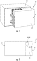
- FIGS. 1 through 2 illustrate one example embodiment of the energy storage system 10, including an energy storage device 12 and an attached battery management system (BMS) 14.
- the BMS 14 is configured to monitor and/or control operation of the energy storage device 12. More specifically, the BMS 14 can be configured to protect the energy storage device 12 from operating outside of safe operation, monitor its state, calculate and report data, control the operating environment, and/or any other suitable control actions needed for device protection.
- One or more controller(s) can be included as part of the BMS 14.
- the controller(s) can include a printed circuit board assembly (PCBA) logic controller implemented purely in hardware, a firmware-programmable digital signal processor, and/or a programmable processor-based software-controlled computer.
- PCBA printed circuit board assembly
- the energy storage device 12 can include one or more batteries that are electrically coupled to a positive terminal 16 and a negative terminal 18. More specifically, in certain embodiments, the energy storage device 12 can include at least one of a lithium ion battery, a sodium nickel chloride battery, a sodium sulfur battery, a nickel metal hydride battery, a nickel cadmium battery, or similar. Moreover, those of ordinary skill in the art, using the disclosures provided herein, should understand that other energy storage devices (e.g. capacitors, fuel cells, etc.) can be used without deviating from the scope of the present disclosure
- the BMS 14 can be attached to a positive 16 and negative terminal 18 of the energy storage device 12.
- a corresponding battery connector of the BMS 14 electrically couples the BMS 14 to the positive 16 and negative terminal 18, and, thereby, the energy storage device 12.
- the BMS 14 can be disposed directly on the energy storage device 12 of some embodiments to readily provide a ready physical and electrical connection between the BMS 14 and energy storage system 10.
- the BMS 14 can include a sidewall 20, top 22, and base 24 which house a controller (not pictured) therein.
- the sidewall 20 can be disposed about the top 22 and base 24, thereby containing multiple BMS elements (e.g., controller, contactors 29, energy storage device couplings 80, 82, etc.).
- An inner surface 26 of the sidewall 20 can be directed toward the contained components, while an outer surface 28 is directed away from the same.
- the power connecter 30 provides an interface with the system and can allow electrical coupling between the system and the BMS 14.
- the power connector 30, itself, can include a body 32 having a first and second face 36. When mounted or attached to the power connector 30, the first face 34 can be directed outward away from the BMS sidewall 20.
- the second face 36 is disposed opposite the first face 34. As a result, when the first face 34 is directed outward, the second face 36 is directed inward toward the BMS sidewall 20.
- the body 32 can also form multiple discrete channels 42, 44, 46. In some embodiments, three separate channels are formed along the first face 34.
- the channels 42, 44, 46 can extend at least partially across the body 32 to receive or hold one or more conductors 62, 64.
- the channels 42, 44, 46 can include one or more inlets 50, 52 defined in the body 32 to receive a selectively removable system conductor 62, 64.
- Certain channel embodiments can include multiple inlets 50, 52.
- Specific channel embodiments can include a first inlet 50 defined a first lateral end 38 of the body 32 and a second inlet 52 defined at an opposite second lateral end 40 of the body 32.
- both the first channel 42 and the second channel 44 can each include respective first and second inlets 50, 52.
- this configuration can allow the power connector 30 to connect to a system conductor 62, 64 disposed through either lateral end 38, 40 of the body 32.
- a separable guard plate 60 can be provided to substantially cover the channels 42, 44, 46, as seen in FIG. 4 .
- the guard plate 60 can selectively attach to the body 32 over the first face 34.
- Certain embodiments of the guard plate 60 can include or more mechanical connectors, such as a retention clip, screw, or nut-and-bolt. Additional or alternative embodiments can be formed to create a friction fit between the guard plate 60 and body 32.
- the guard 60 can be configured to allow inlet access.
- the attached guard 60 is positioned over the channel inlets 50, 52. As a result, an orifice is formed, allowing the system conductors 62, 64 to extend therethrough.
- Some embodiments according to the invention include a first terminal 54 and a second terminal 56 disposed on the first face 34 of the body 32, as illustrated in FIG. 5 .
- the first terminal 54 and the second terminal 56 can interface in physical connection with a positive system conductor 62 and negative system conductor 64.
- conductors 62, 64 can electrically couple the first terminal 54 and the second terminal 56 to the positive 62 and negative system conductors 64.
- the conductors 62, 64 can further couple the BMS 14 to the positive 62 and negative system conductors 64.
- a power connection can be selectively formed between the BMS 14 and the system conductors 62, 64.
- a fuse 58 is also be disposed on the first face 34.
- the fuse 58 can monitor current through the system 10.
- the fuse 58 of certain embodiments can be formed to detect a current threshold between at least one terminal 54, 56 and shunt 68, 70.
- detecting a current threshold includes deforming upon reaching the threshold. In such instances, the fuse's deformation will open an electrical circuit, preventing further transmission of any excessive currents.
- heat can be generated at the fuse 58 during operation, the heat can be advantageously directed from the front face and away from enclosed BMS elements (e.g., PCBA).
- the first channel 42 and the second channel 44 receive respective first and second terminals 54, 56.
- a third channel 46 can receive a fuse 58 coupled to the first terminal 54 or the second terminal 56.
- a coupling passage 48 can be formed from at least one of the first and second channel 42, 44 to the third channel 46, allowing a coupling element to extend therethrough.
- the first terminal 54 and the second terminal 56 can be disposed on the first face 34 for connection with the one or more system conductor 62, 64.
- the first terminal 54 can receive a positive system conductor 62 while the second terminal 56 can receive a negative system conductor 64.
- the connection between the terminals 54, 56 and the conductors 62, 64 can electrically couple the system to the power connector 30, or be selectively disconnected to uncouple the system.
- some embodiments according to the invention include one or more current shunts 68, 70 disposed on the body 32 of the power connector 30.
- certain shunt embodiments 68, 70 can be disposed on the second face 36 of the body 32 and directed toward the BMS 14.
- the shunts 68, 70 can include discrete first and second shunts 68, 70 each having a first end 72 and a second end 74.
- both the first shunt 68 and the second shunt 70 can be electrically coupled at their respective first ends 72.
- Embodiments according to the invention that include a fuse 58 can be configured such that the fuse 58 is electrically coupled between one terminal 54, 56 and one current shunt 68, 70.
- the fuse 58 can be electrically coupled between the second terminal 56 and the second current shunt 70.
- the fuse 58 can be electrically coupled between the first terminal 54 and the first current shunt 68.
- some embodiments further include one or more bus bars 76, 78 attached to the shunts 68, 70 and extending into the BMS 14.
- a first bus bar 76 and a second bus bar 78 can be included.
- the first bus bar 76 can be connected to a second end 74 of the first shunt 68 while the second bus bar 78 can be connected to a second end 74 of the second shunt 70.
- the bus bars 76, 78 can extend through the BMS sidewall 20 and at least partially within the enclosed area of the BMS 14 to electrically couple the shunts 68, 70 to the energy storage device terminals 16, 18.
- one or more mechanical fasteners such as a mated prong or nut-and-bolt connector may attach the bus bars 76, 78 to the shunts 68, 70.
- One or more energy storage device coupling including a positive coupling 80 and a negative coupling 82, can connect the bus bars 76, 78 to the energy storage device terminals.
- bus bars 76, 78 include rigid electrically-conductive rail formed from a conductive material (e.g., copper, aluminum, steel, etc.).
- One or more BMS elements e.g., controller, contactors 29, energy storage device couplings 80, 82, etc.
- the bus bars 76, 78 can form a matched path through the BMS 14.
- the path of the first bus bar 76 between the first current shunt 68 and the positive terminal 16 can be primarily parallel to the path of the second bus bar 78 between the second current shunt 70 and the negative terminal 18.
- the path can be configured to substantially cancel EMI emissions from inductance generated at the bus bars 76, 78.
Landscapes
- Engineering & Computer Science (AREA)
- Power Engineering (AREA)
- Chemical & Material Sciences (AREA)
- Chemical Kinetics & Catalysis (AREA)
- Electrochemistry (AREA)
- General Chemical & Material Sciences (AREA)
- Connection Of Batteries Or Terminals (AREA)
- Charge And Discharge Circuits For Batteries Or The Like (AREA)
- Manufacturing & Machinery (AREA)
Claims (13)
- Connecteur de puissance (30) permettant de connecter un système de gestion de batterie (BMS) (14), le connecteur de puissance (30) comprenant :un corps de connecteur (32), présentant une première face (34) et une seconde face opposée (36) ;une première borne (54), disposée sur la première face (34) ;une seconde borne (56), disposée sur la première face (34), la première borne (54) et la seconde borne (56) étant conçues pour coupler électriquement le système de gestion de batterie (14) à des conducteurs positifs (62) et négatifs (64) pour former une connexion de puissance ;un premier shunt de courant (68), disposé sur la seconde face (36) et couplé électriquement à la première borne (54) ;un second shunt de courant (70), disposé sur la seconde face (36) et couplé électriquement à la seconde borne ; etun fusible (58), disposé sur la première face (34) du corps de connecteur (32), le premier shunt de courant (68) présentant une première extrémité (72) couplée électriquement au fusible (58) et une seconde extrémité (74) connectée à une première barre omnibus (76), tandis que le second shunt de courant (70) présente une première extrémité (72), couplée électriquement à la seconde borne (56), et une seconde extrémité (74), connectée à une seconde barre omnibus (78).
- Connecteur de puissance (30) selon la revendication 1, dans lequel le fusible (58) est couplé électriquement entre la première borne (54) et le premier shunt de courant (68).
- Connecteur de puissance (30) selon la revendication 1, dans lequel le corps de connecteur (32) définit un premier canal (42), conçu pour recevoir le conducteur positif (62), un deuxième canal (44), conçu pour recevoir le conducteur négatif (64) et un troisième canal (46), situé sur la première face (34), la première borne (54) étant disposée dans le premier canal (42), la seconde borne (56) étant disposée dans le deuxième canal (44) et le fusible (58) étant disposé dans le troisième canal (46).
- Connecteur de puissance (30) selon la revendication 1, comprenant en outre une barre omnibus positive, connectée au premier shunt de courant (68), et une barre omnibus négative, connectée au second shunt de courant (70), la barre omnibus positive et la barre omnibus négative étant des éléments rigides et discrets s'étendant au moins partiellement à travers le BMS (14).
- Procédé d'établissement d'une connexion de puissance pour un système de gestion de batterie (14), le procédé comprenant :l'accès à un connecteur de puissance (30) d'un système de gestion de batterie (14), le connecteur de puissance (30) comprenant une première borne (54) et une seconde borne (56) ;le couplage d'un premier conducteur de puissance (62) à la première borne (54) ; etle couplage d'un second conducteur de puissance (64) à la seconde borne (56) ;dans lequel le connecteur de puissance (30) comprend un fusible (58), un premier shunt de courant (68) et un second shunt de courant (70) ;dans lequel le connecteur de puissance (30) comprend un corps de connecteur (32) présentant une première face (34) et une seconde face opposée (36) ; la première borne (54) étant disposée sur la première face (34) et la seconde borne (56) étant disposée sur la première face (34) ;
dans lequel le premier shunt de courant (68) est disposé sur la seconde face (36) et est couplé électriquement à la première borne (54) ;
le second shunt de courant (70) est disposé sur la seconde face (36) et est couplé électriquement à la seconde borne ; et
le fusible (58) est disposé sur la première face (34) du corps de connecteur (32), le premier shunt de courant (68) présentant une première extrémité (72), couplée électriquement au fusible (58), et une seconde extrémité (74), connectée à une première barre omnibus (76), tandis que le second shunt de courant (70) présente une première extrémité (72) couplée électriquement à la seconde borne (56) et une seconde extrémité (74) connectée à une seconde barre omnibus (78). - Procédé selon la revendication 5, dans lequel le fusible (58), le premier shunt de courant (68) et le second shunt de courant (70) sont accessibles sans devoir régler une carte de circuit imprimé associée au système de gestion de batterie (14).
- Procédé selon la revendication 5, le procédé comprenant le placement d'une plaque de protection séparable (60) sur le connecteur de puissance (30).
- Procédé selon la revendication 5, dans lequel le corps de connecteur (32) définit :un premier canal (42) sur la première face (34), le premier canal (42) étant conçu pour recevoir le premier conducteur de puissance (62) ;un deuxième canal (44) sur la première face (34), le deuxième canal (44) étant conçu pour recevoir le second conducteur de puissance (64) ; etun troisième canal (46) sur la première face (34) ;la première borne (54) étant disposée dans le premier canal (42), la seconde borne (56) étant disposée dans le deuxième canal (44) et le fusible (58) étant disposé dans le troisième canal (46).
- Système de stockage d'énergie (10), comprenant :un dispositif de stockage d'énergie (12) comprenant des bornes positive (16) et négative (18) ;un système de gestion de batterie (14), configuré pour surveiller et pour commander le dispositif de stockage d'énergie (12) ; etun connecteur de puissance (30) selon la revendication 1.
- Système de stockage d'énergie (10) selon la revendication 9, dans lequel le corps de connecteur (32) définit un premier canal (42), conçu pour recevoir le conducteur positif (62), un deuxième canal (44), conçu pour recevoir le conducteur négatif (64), et un troisième canal (46), situé sur la première face (34).
- Système de stockage d'énergie (10) selon la revendication 12, dans lequel la première borne (54) est disposée dans le premier canal (42), la seconde borne (56) est disposée dans le deuxième canal (44) et le fusible (58) est disposé dans le troisième canal (46).
- Système de stockage d'énergie (10) selon la revendication 9, comprenant en outre une barre omnibus positive, connectée au premier shunt de courant, et une barre omnibus négative, connectée au second shunt de courant, la barre omnibus positive et la barre omnibus négative étant éventuellement des éléments rigides et discrets s'étendant au moins partiellement à travers le BMS (14).
- Système de stockage d'énergie (10) selon la revendication 9, dans lequel le connecteur de puissance (30) est disposé sur une paroi latérale (20) du BMS (14), dans lequel la première face (34) est dirigée vers l'extérieur, à l'opposé de la paroi latérale du BMS (20) et dans lequel la seconde face (36) est dirigée vers l'intérieur, vers la paroi latérale du BMS (20).
Applications Claiming Priority (2)
| Application Number | Priority Date | Filing Date | Title |
|---|---|---|---|
| US14/840,702 US9692245B2 (en) | 2015-08-31 | 2015-08-31 | Battery management system and power connector |
| PCT/US2016/043279 WO2017039860A1 (fr) | 2015-08-31 | 2016-07-21 | Système de gestion de batterie et connecteur de puissance |
Publications (2)
| Publication Number | Publication Date |
|---|---|
| EP3345233A1 EP3345233A1 (fr) | 2018-07-11 |
| EP3345233B1 true EP3345233B1 (fr) | 2021-02-17 |
Family
ID=56551610
Family Applications (1)
| Application Number | Title | Priority Date | Filing Date |
|---|---|---|---|
| EP16745027.9A Active EP3345233B1 (fr) | 2015-08-31 | 2016-07-21 | Système de gestion de batterie et connecteur de puissance |
Country Status (4)
| Country | Link |
|---|---|
| US (1) | US9692245B2 (fr) |
| EP (1) | EP3345233B1 (fr) |
| CN (1) | CN107925046B (fr) |
| WO (1) | WO2017039860A1 (fr) |
Families Citing this family (1)
| Publication number | Priority date | Publication date | Assignee | Title |
|---|---|---|---|---|
| DE102019124873A1 (de) * | 2019-09-16 | 2021-03-18 | Jungheinrich Aktiengesellschaft | Flurförderzeug mit einem elektrischen Energiespeicher |
Family Cites Families (13)
| Publication number | Priority date | Publication date | Assignee | Title |
|---|---|---|---|---|
| IL136235A0 (en) * | 1997-11-17 | 2001-05-20 | Lifestyle Technologies | Universal power supply |
| US6628102B2 (en) * | 2001-04-06 | 2003-09-30 | Microchip Technology Inc. | Current measuring terminal assembly for a battery |
| EP1469564B1 (fr) * | 2003-04-17 | 2012-12-05 | Autoliv Development AB | Borne de batterie pyrotechnique |
| US7943252B2 (en) * | 2007-11-21 | 2011-05-17 | Lg Chem, Ltd. | Battery module of improved safety and middle or large-sized battery pack containing the same |
| US8080975B2 (en) * | 2008-05-09 | 2011-12-20 | Ipowerup, Inc. | Portable and universal hybrid-charging apparatus for portable electronic devices |
| US8523576B2 (en) * | 2011-10-24 | 2013-09-03 | GM Global Technology Operations LLC | Connector for coupling an electric motor to a power source |
| US8808031B2 (en) * | 2011-12-14 | 2014-08-19 | Tyco Electronics Corporation | Battery connector system |
| CN202593301U (zh) * | 2012-04-05 | 2012-12-12 | 郑州宇通客车股份有限公司 | 一种通用化的电动汽车高压安全控制装置 |
| US8934264B2 (en) * | 2012-05-09 | 2015-01-13 | Robert Bosch Gmbh | Inverted base battery disconnect unit |
| US9660244B2 (en) * | 2013-09-06 | 2017-05-23 | Johnson Controls Technology Company | System and method for establishing connections of a battery module |
| KR102197409B1 (ko) * | 2013-11-12 | 2020-12-31 | 삼성에스디아이 주식회사 | 배터리 팩 및 이를 이용한 배터리 팩 보호 방법 |
| US9581342B2 (en) * | 2014-03-28 | 2017-02-28 | Google Inc. | Mounting stand for multi-sensing environmental control device |
| CN204243103U (zh) * | 2014-08-18 | 2015-04-01 | 浙江超威创元实业有限公司 | 一种电池结构及包含有电池结构的电动车 |
-
2015
- 2015-08-31 US US14/840,702 patent/US9692245B2/en active Active
-
2016
- 2016-07-21 CN CN201680050332.8A patent/CN107925046B/zh active Active
- 2016-07-21 WO PCT/US2016/043279 patent/WO2017039860A1/fr not_active Ceased
- 2016-07-21 EP EP16745027.9A patent/EP3345233B1/fr active Active
Non-Patent Citations (1)
| Title |
|---|
| None * |
Also Published As
| Publication number | Publication date |
|---|---|
| US9692245B2 (en) | 2017-06-27 |
| WO2017039860A1 (fr) | 2017-03-09 |
| EP3345233A1 (fr) | 2018-07-11 |
| CN107925046B (zh) | 2021-06-01 |
| US20170062994A1 (en) | 2017-03-02 |
| CN107925046A (zh) | 2018-04-17 |
Similar Documents
| Publication | Publication Date | Title |
|---|---|---|
| US11313885B2 (en) | Integrated current-measuring apparatus | |
| CN107528020B (zh) | 二次电池组 | |
| EP3734746A1 (fr) | Circuit et procédé de détection d'emballement thermique | |
| US20170338520A1 (en) | Battery device and battery connection module | |
| KR102103215B1 (ko) | 배터리 시스템용 수동 서비스 분리장치 | |
| US20140141287A1 (en) | Battery pack and battery control module | |
| US9718420B1 (en) | Integrated power electronic device for electric vehicles | |
| KR101853397B1 (ko) | 전지모듈 | |
| CN107528019A (zh) | 二次电池组 | |
| EP2784841A1 (fr) | Connecteur pour unité de cellule, et unité de cellule le comportant | |
| WO2015167046A1 (fr) | Carte de circuits imprimés pour batterie secondaire et bloc-batterie la comprenant | |
| US9011180B2 (en) | Connector with integrated fuse | |
| KR102098906B1 (ko) | 솔더 크랙 방지구조를 갖는 션트 저항 모듈 | |
| KR102662704B1 (ko) | 배터리 시스템용 수동 서비스 분리 장치 | |
| US10938000B2 (en) | Arrangement for battery pack protection during fluid ingress | |
| US9647470B2 (en) | Rechargeable battery system | |
| US20240072385A1 (en) | Power supply including a touch safe power supply core | |
| EP3345233B1 (fr) | Système de gestion de batterie et connecteur de puissance | |
| CN106410469B (zh) | 连接器插座、连接器组件、电池汇流排组件及电池装置 | |
| CN116169422B (zh) | 一种标准化动力电池模组与采集板连接结构及其连接方法 | |
| CN219226560U (zh) | 电池包断路装置及电池包 | |
| CN115606036A (zh) | 电池模块的端部连接件 | |
| CN221651587U (zh) | 配电装置、电池及用电设备 | |
| CN223809612U (zh) | 一种工商业储能交直流插箱组件 | |
| CN218386889U (zh) | 电源分配组件及电池组件 |
Legal Events
| Date | Code | Title | Description |
|---|---|---|---|
| STAA | Information on the status of an ep patent application or granted ep patent |
Free format text: STATUS: THE INTERNATIONAL PUBLICATION HAS BEEN MADE |
|
| PUAI | Public reference made under article 153(3) epc to a published international application that has entered the european phase |
Free format text: ORIGINAL CODE: 0009012 |
|
| STAA | Information on the status of an ep patent application or granted ep patent |
Free format text: STATUS: REQUEST FOR EXAMINATION WAS MADE |
|
| 17P | Request for examination filed |
Effective date: 20180403 |
|
| AK | Designated contracting states |
Kind code of ref document: A1 Designated state(s): AL AT BE BG CH CY CZ DE DK EE ES FI FR GB GR HR HU IE IS IT LI LT LU LV MC MK MT NL NO PL PT RO RS SE SI SK SM TR |
|
| AX | Request for extension of the european patent |
Extension state: BA ME |
|
| DAV | Request for validation of the european patent (deleted) | ||
| DAX | Request for extension of the european patent (deleted) | ||
| STAA | Information on the status of an ep patent application or granted ep patent |
Free format text: STATUS: EXAMINATION IS IN PROGRESS |
|
| 17Q | First examination report despatched |
Effective date: 20190716 |
|
| REG | Reference to a national code |
Ref country code: DE Ref legal event code: R079 Ref document number: 602016052585 Country of ref document: DE Free format text: PREVIOUS MAIN CLASS: H01M0002340000 Ipc: H01R0013660000 |
|
| RIC1 | Information provided on ipc code assigned before grant |
Ipc: H01R 13/696 20110101ALI20200803BHEP Ipc: H01R 13/684 20110101ALI20200803BHEP Ipc: H01M 2/34 20060101ALI20200803BHEP Ipc: H02J 7/00 20060101ALI20200803BHEP Ipc: H01R 13/66 20060101AFI20200803BHEP Ipc: H01M 10/42 20060101ALI20200803BHEP |
|
| GRAP | Despatch of communication of intention to grant a patent |
Free format text: ORIGINAL CODE: EPIDOSNIGR1 |
|
| STAA | Information on the status of an ep patent application or granted ep patent |
Free format text: STATUS: GRANT OF PATENT IS INTENDED |
|
| INTG | Intention to grant announced |
Effective date: 20201020 |
|
| GRAS | Grant fee paid |
Free format text: ORIGINAL CODE: EPIDOSNIGR3 |
|
| GRAA | (expected) grant |
Free format text: ORIGINAL CODE: 0009210 |
|
| STAA | Information on the status of an ep patent application or granted ep patent |
Free format text: STATUS: THE PATENT HAS BEEN GRANTED |
|
| AK | Designated contracting states |
Kind code of ref document: B1 Designated state(s): AL AT BE BG CH CY CZ DE DK EE ES FI FR GB GR HR HU IE IS IT LI LT LU LV MC MK MT NL NO PL PT RO RS SE SI SK SM TR |
|
| REG | Reference to a national code |
Ref country code: GB Ref legal event code: FG4D |
|
| REG | Reference to a national code |
Ref country code: CH Ref legal event code: EP |
|
| REG | Reference to a national code |
Ref country code: DE Ref legal event code: R096 Ref document number: 602016052585 Country of ref document: DE |
|
| REG | Reference to a national code |
Ref country code: AT Ref legal event code: REF Ref document number: 1362715 Country of ref document: AT Kind code of ref document: T Effective date: 20210315 |
|
| REG | Reference to a national code |
Ref country code: IE Ref legal event code: FG4D |
|
| REG | Reference to a national code |
Ref country code: LT Ref legal event code: MG9D |
|
| REG | Reference to a national code |
Ref country code: NL Ref legal event code: MP Effective date: 20210217 |
|
| PG25 | Lapsed in a contracting state [announced via postgrant information from national office to epo] |
Ref country code: NO Free format text: LAPSE BECAUSE OF FAILURE TO SUBMIT A TRANSLATION OF THE DESCRIPTION OR TO PAY THE FEE WITHIN THE PRESCRIBED TIME-LIMIT Effective date: 20210517 Ref country code: PT Free format text: LAPSE BECAUSE OF FAILURE TO SUBMIT A TRANSLATION OF THE DESCRIPTION OR TO PAY THE FEE WITHIN THE PRESCRIBED TIME-LIMIT Effective date: 20210617 Ref country code: BG Free format text: LAPSE BECAUSE OF FAILURE TO SUBMIT A TRANSLATION OF THE DESCRIPTION OR TO PAY THE FEE WITHIN THE PRESCRIBED TIME-LIMIT Effective date: 20210517 Ref country code: LT Free format text: LAPSE BECAUSE OF FAILURE TO SUBMIT A TRANSLATION OF THE DESCRIPTION OR TO PAY THE FEE WITHIN THE PRESCRIBED TIME-LIMIT Effective date: 20210217 Ref country code: FI Free format text: LAPSE BECAUSE OF FAILURE TO SUBMIT A TRANSLATION OF THE DESCRIPTION OR TO PAY THE FEE WITHIN THE PRESCRIBED TIME-LIMIT Effective date: 20210217 Ref country code: HR Free format text: LAPSE BECAUSE OF FAILURE TO SUBMIT A TRANSLATION OF THE DESCRIPTION OR TO PAY THE FEE WITHIN THE PRESCRIBED TIME-LIMIT Effective date: 20210217 Ref country code: GR Free format text: LAPSE BECAUSE OF FAILURE TO SUBMIT A TRANSLATION OF THE DESCRIPTION OR TO PAY THE FEE WITHIN THE PRESCRIBED TIME-LIMIT Effective date: 20210518 |
|
| REG | Reference to a national code |
Ref country code: AT Ref legal event code: MK05 Ref document number: 1362715 Country of ref document: AT Kind code of ref document: T Effective date: 20210217 |
|
| PG25 | Lapsed in a contracting state [announced via postgrant information from national office to epo] |
Ref country code: SE Free format text: LAPSE BECAUSE OF FAILURE TO SUBMIT A TRANSLATION OF THE DESCRIPTION OR TO PAY THE FEE WITHIN THE PRESCRIBED TIME-LIMIT Effective date: 20210217 Ref country code: PL Free format text: LAPSE BECAUSE OF FAILURE TO SUBMIT A TRANSLATION OF THE DESCRIPTION OR TO PAY THE FEE WITHIN THE PRESCRIBED TIME-LIMIT Effective date: 20210217 Ref country code: RS Free format text: LAPSE BECAUSE OF FAILURE TO SUBMIT A TRANSLATION OF THE DESCRIPTION OR TO PAY THE FEE WITHIN THE PRESCRIBED TIME-LIMIT Effective date: 20210217 Ref country code: NL Free format text: LAPSE BECAUSE OF FAILURE TO SUBMIT A TRANSLATION OF THE DESCRIPTION OR TO PAY THE FEE WITHIN THE PRESCRIBED TIME-LIMIT Effective date: 20210217 Ref country code: LV Free format text: LAPSE BECAUSE OF FAILURE TO SUBMIT A TRANSLATION OF THE DESCRIPTION OR TO PAY THE FEE WITHIN THE PRESCRIBED TIME-LIMIT Effective date: 20210217 |
|
| PG25 | Lapsed in a contracting state [announced via postgrant information from national office to epo] |
Ref country code: IS Free format text: LAPSE BECAUSE OF FAILURE TO SUBMIT A TRANSLATION OF THE DESCRIPTION OR TO PAY THE FEE WITHIN THE PRESCRIBED TIME-LIMIT Effective date: 20210617 |
|
| PG25 | Lapsed in a contracting state [announced via postgrant information from national office to epo] |
Ref country code: CZ Free format text: LAPSE BECAUSE OF FAILURE TO SUBMIT A TRANSLATION OF THE DESCRIPTION OR TO PAY THE FEE WITHIN THE PRESCRIBED TIME-LIMIT Effective date: 20210217 Ref country code: EE Free format text: LAPSE BECAUSE OF FAILURE TO SUBMIT A TRANSLATION OF THE DESCRIPTION OR TO PAY THE FEE WITHIN THE PRESCRIBED TIME-LIMIT Effective date: 20210217 Ref country code: AT Free format text: LAPSE BECAUSE OF FAILURE TO SUBMIT A TRANSLATION OF THE DESCRIPTION OR TO PAY THE FEE WITHIN THE PRESCRIBED TIME-LIMIT Effective date: 20210217 Ref country code: SM Free format text: LAPSE BECAUSE OF FAILURE TO SUBMIT A TRANSLATION OF THE DESCRIPTION OR TO PAY THE FEE WITHIN THE PRESCRIBED TIME-LIMIT Effective date: 20210217 |
|
| REG | Reference to a national code |
Ref country code: DE Ref legal event code: R097 Ref document number: 602016052585 Country of ref document: DE |
|
| PG25 | Lapsed in a contracting state [announced via postgrant information from national office to epo] |
Ref country code: DK Free format text: LAPSE BECAUSE OF FAILURE TO SUBMIT A TRANSLATION OF THE DESCRIPTION OR TO PAY THE FEE WITHIN THE PRESCRIBED TIME-LIMIT Effective date: 20210217 Ref country code: SK Free format text: LAPSE BECAUSE OF FAILURE TO SUBMIT A TRANSLATION OF THE DESCRIPTION OR TO PAY THE FEE WITHIN THE PRESCRIBED TIME-LIMIT Effective date: 20210217 Ref country code: RO Free format text: LAPSE BECAUSE OF FAILURE TO SUBMIT A TRANSLATION OF THE DESCRIPTION OR TO PAY THE FEE WITHIN THE PRESCRIBED TIME-LIMIT Effective date: 20210217 |
|
| PLBE | No opposition filed within time limit |
Free format text: ORIGINAL CODE: 0009261 |
|
| STAA | Information on the status of an ep patent application or granted ep patent |
Free format text: STATUS: NO OPPOSITION FILED WITHIN TIME LIMIT |
|
| 26N | No opposition filed |
Effective date: 20211118 |
|
| PG25 | Lapsed in a contracting state [announced via postgrant information from national office to epo] |
Ref country code: ES Free format text: LAPSE BECAUSE OF FAILURE TO SUBMIT A TRANSLATION OF THE DESCRIPTION OR TO PAY THE FEE WITHIN THE PRESCRIBED TIME-LIMIT Effective date: 20210217 Ref country code: AL Free format text: LAPSE BECAUSE OF FAILURE TO SUBMIT A TRANSLATION OF THE DESCRIPTION OR TO PAY THE FEE WITHIN THE PRESCRIBED TIME-LIMIT Effective date: 20210217 |
|
| PG25 | Lapsed in a contracting state [announced via postgrant information from national office to epo] |
Ref country code: SI Free format text: LAPSE BECAUSE OF FAILURE TO SUBMIT A TRANSLATION OF THE DESCRIPTION OR TO PAY THE FEE WITHIN THE PRESCRIBED TIME-LIMIT Effective date: 20210217 |
|
| REG | Reference to a national code |
Ref country code: CH Ref legal event code: PL |
|
| PG25 | Lapsed in a contracting state [announced via postgrant information from national office to epo] |
Ref country code: MC Free format text: LAPSE BECAUSE OF FAILURE TO SUBMIT A TRANSLATION OF THE DESCRIPTION OR TO PAY THE FEE WITHIN THE PRESCRIBED TIME-LIMIT Effective date: 20210217 |
|
| REG | Reference to a national code |
Ref country code: BE Ref legal event code: MM Effective date: 20210731 |
|
| PG25 | Lapsed in a contracting state [announced via postgrant information from national office to epo] |
Ref country code: LI Free format text: LAPSE BECAUSE OF NON-PAYMENT OF DUE FEES Effective date: 20210731 Ref country code: IT Free format text: LAPSE BECAUSE OF FAILURE TO SUBMIT A TRANSLATION OF THE DESCRIPTION OR TO PAY THE FEE WITHIN THE PRESCRIBED TIME-LIMIT Effective date: 20210217 Ref country code: CH Free format text: LAPSE BECAUSE OF NON-PAYMENT OF DUE FEES Effective date: 20210731 |
|
| PG25 | Lapsed in a contracting state [announced via postgrant information from national office to epo] |
Ref country code: IS Free format text: LAPSE BECAUSE OF FAILURE TO SUBMIT A TRANSLATION OF THE DESCRIPTION OR TO PAY THE FEE WITHIN THE PRESCRIBED TIME-LIMIT Effective date: 20210617 Ref country code: LU Free format text: LAPSE BECAUSE OF NON-PAYMENT OF DUE FEES Effective date: 20210721 |
|
| PG25 | Lapsed in a contracting state [announced via postgrant information from national office to epo] |
Ref country code: IE Free format text: LAPSE BECAUSE OF NON-PAYMENT OF DUE FEES Effective date: 20210721 Ref country code: BE Free format text: LAPSE BECAUSE OF NON-PAYMENT OF DUE FEES Effective date: 20210731 |
|
| PG25 | Lapsed in a contracting state [announced via postgrant information from national office to epo] |
Ref country code: HU Free format text: LAPSE BECAUSE OF FAILURE TO SUBMIT A TRANSLATION OF THE DESCRIPTION OR TO PAY THE FEE WITHIN THE PRESCRIBED TIME-LIMIT; INVALID AB INITIO Effective date: 20160721 |
|
| PG25 | Lapsed in a contracting state [announced via postgrant information from national office to epo] |
Ref country code: CY Free format text: LAPSE BECAUSE OF FAILURE TO SUBMIT A TRANSLATION OF THE DESCRIPTION OR TO PAY THE FEE WITHIN THE PRESCRIBED TIME-LIMIT Effective date: 20210217 |
|
| P01 | Opt-out of the competence of the unified patent court (upc) registered |
Effective date: 20230528 |
|
| PG25 | Lapsed in a contracting state [announced via postgrant information from national office to epo] |
Ref country code: MK Free format text: LAPSE BECAUSE OF FAILURE TO SUBMIT A TRANSLATION OF THE DESCRIPTION OR TO PAY THE FEE WITHIN THE PRESCRIBED TIME-LIMIT Effective date: 20210217 |
|
| PG25 | Lapsed in a contracting state [announced via postgrant information from national office to epo] |
Ref country code: MT Free format text: LAPSE BECAUSE OF FAILURE TO SUBMIT A TRANSLATION OF THE DESCRIPTION OR TO PAY THE FEE WITHIN THE PRESCRIBED TIME-LIMIT Effective date: 20210217 |
|
| PGFP | Annual fee paid to national office [announced via postgrant information from national office to epo] |
Ref country code: DE Payment date: 20250729 Year of fee payment: 10 |
|
| PGFP | Annual fee paid to national office [announced via postgrant information from national office to epo] |
Ref country code: GB Payment date: 20250728 Year of fee payment: 10 |
|
| PGFP | Annual fee paid to national office [announced via postgrant information from national office to epo] |
Ref country code: FR Payment date: 20250725 Year of fee payment: 10 |
|
| PG25 | Lapsed in a contracting state [announced via postgrant information from national office to epo] |
Ref country code: TR Free format text: LAPSE BECAUSE OF FAILURE TO SUBMIT A TRANSLATION OF THE DESCRIPTION OR TO PAY THE FEE WITHIN THE PRESCRIBED TIME-LIMIT Effective date: 20210217 |