EP3346913B1 - Ensemble de cathéter comprenant des capacités de surveillance - Google Patents
Ensemble de cathéter comprenant des capacités de surveillance Download PDFInfo
- Publication number
- EP3346913B1 EP3346913B1 EP16849804.6A EP16849804A EP3346913B1 EP 3346913 B1 EP3346913 B1 EP 3346913B1 EP 16849804 A EP16849804 A EP 16849804A EP 3346913 B1 EP3346913 B1 EP 3346913B1
- Authority
- EP
- European Patent Office
- Prior art keywords
- sensor
- catheter assembly
- catheter
- patient
- fluid
- Prior art date
- Legal status (The legal status is an assumption and is not a legal conclusion. Google has not performed a legal analysis and makes no representation as to the accuracy of the status listed.)
- Active
Links
Images


Classifications
-
- A—HUMAN NECESSITIES
- A61—MEDICAL OR VETERINARY SCIENCE; HYGIENE
- A61B—DIAGNOSIS; SURGERY; IDENTIFICATION
- A61B5/00—Measuring for diagnostic purposes; Identification of persons
- A61B5/0002—Remote monitoring of patients using telemetry, e.g. transmission of vital signals via a communication network
- A61B5/0015—Remote monitoring of patients using telemetry, e.g. transmission of vital signals via a communication network characterised by features of the telemetry system
- A61B5/0022—Monitoring a patient using a global network, e.g. telephone networks, internet
-
- A—HUMAN NECESSITIES
- A61—MEDICAL OR VETERINARY SCIENCE; HYGIENE
- A61B—DIAGNOSIS; SURGERY; IDENTIFICATION
- A61B5/00—Measuring for diagnostic purposes; Identification of persons
- A61B5/02—Detecting, measuring or recording for evaluating the cardiovascular system, e.g. pulse, heart rate, blood pressure or blood flow
- A61B5/0205—Simultaneously evaluating both cardiovascular conditions and different types of body conditions, e.g. heart and respiratory condition
- A61B5/02055—Simultaneously evaluating both cardiovascular condition and temperature
-
- A—HUMAN NECESSITIES
- A61—MEDICAL OR VETERINARY SCIENCE; HYGIENE
- A61B—DIAGNOSIS; SURGERY; IDENTIFICATION
- A61B5/00—Measuring for diagnostic purposes; Identification of persons
- A61B5/24—Detecting, measuring or recording bioelectric or biomagnetic signals of the body or parts thereof
- A61B5/25—Bioelectric electrodes therefor
- A61B5/279—Bioelectric electrodes therefor specially adapted for particular uses
- A61B5/28—Bioelectric electrodes therefor specially adapted for particular uses for electrocardiography [ECG]
- A61B5/283—Invasive
-
- A—HUMAN NECESSITIES
- A61—MEDICAL OR VETERINARY SCIENCE; HYGIENE
- A61B—DIAGNOSIS; SURGERY; IDENTIFICATION
- A61B5/00—Measuring for diagnostic purposes; Identification of persons
- A61B5/24—Detecting, measuring or recording bioelectric or biomagnetic signals of the body or parts thereof
- A61B5/316—Modalities, i.e. specific diagnostic methods
- A61B5/318—Heart-related electrical modalities, e.g. electrocardiography [ECG]
- A61B5/33—Heart-related electrical modalities, e.g. electrocardiography [ECG] specially adapted for cooperation with other devices
-
- A—HUMAN NECESSITIES
- A61—MEDICAL OR VETERINARY SCIENCE; HYGIENE
- A61B—DIAGNOSIS; SURGERY; IDENTIFICATION
- A61B5/00—Measuring for diagnostic purposes; Identification of persons
- A61B5/68—Arrangements of detecting, measuring or recording means, e.g. sensors, in relation to patient
- A61B5/6846—Arrangements of detecting, measuring or recording means, e.g. sensors, in relation to patient specially adapted to be brought in contact with an internal body part, i.e. invasive
- A61B5/6847—Arrangements of detecting, measuring or recording means, e.g. sensors, in relation to patient specially adapted to be brought in contact with an internal body part, i.e. invasive mounted on an invasive device
- A61B5/6852—Catheters
-
- A—HUMAN NECESSITIES
- A61—MEDICAL OR VETERINARY SCIENCE; HYGIENE
- A61B—DIAGNOSIS; SURGERY; IDENTIFICATION
- A61B5/00—Measuring for diagnostic purposes; Identification of persons
- A61B5/74—Details of notification to user or communication with user or patient; User input means
- A61B5/746—Alarms related to a physiological condition, e.g. details of setting alarm thresholds or avoiding false alarms
-
- A—HUMAN NECESSITIES
- A61—MEDICAL OR VETERINARY SCIENCE; HYGIENE
- A61B—DIAGNOSIS; SURGERY; IDENTIFICATION
- A61B8/00—Diagnosis using ultrasonic, sonic or infrasonic waves
- A61B8/12—Diagnosis using ultrasonic, sonic or infrasonic waves in body cavities or body tracts, e.g. by using catheters
-
- A—HUMAN NECESSITIES
- A61—MEDICAL OR VETERINARY SCIENCE; HYGIENE
- A61M—DEVICES FOR INTRODUCING MEDIA INTO, OR ONTO, THE BODY; DEVICES FOR TRANSDUCING BODY MEDIA OR FOR TAKING MEDIA FROM THE BODY; DEVICES FOR PRODUCING OR ENDING SLEEP OR STUPOR
- A61M25/00—Catheters; Hollow probes
- A61M25/0097—Catheters; Hollow probes characterised by the hub
-
- A—HUMAN NECESSITIES
- A61—MEDICAL OR VETERINARY SCIENCE; HYGIENE
- A61M—DEVICES FOR INTRODUCING MEDIA INTO, OR ONTO, THE BODY; DEVICES FOR TRANSDUCING BODY MEDIA OR FOR TAKING MEDIA FROM THE BODY; DEVICES FOR PRODUCING OR ENDING SLEEP OR STUPOR
- A61M25/00—Catheters; Hollow probes
- A61M25/01—Introducing, guiding, advancing, emplacing or holding catheters
- A61M25/02—Holding devices, e.g. on the body
-
- G—PHYSICS
- G16—INFORMATION AND COMMUNICATION TECHNOLOGY [ICT] SPECIALLY ADAPTED FOR SPECIFIC APPLICATION FIELDS
- G16H—HEALTHCARE INFORMATICS, i.e. INFORMATION AND COMMUNICATION TECHNOLOGY [ICT] SPECIALLY ADAPTED FOR THE HANDLING OR PROCESSING OF MEDICAL OR HEALTHCARE DATA
- G16H40/00—ICT specially adapted for the management or administration of healthcare resources or facilities; ICT specially adapted for the management or operation of medical equipment or devices
- G16H40/60—ICT specially adapted for the management or administration of healthcare resources or facilities; ICT specially adapted for the management or operation of medical equipment or devices for the operation of medical equipment or devices
- G16H40/67—ICT specially adapted for the management or administration of healthcare resources or facilities; ICT specially adapted for the management or operation of medical equipment or devices for the operation of medical equipment or devices for remote operation
-
- A—HUMAN NECESSITIES
- A61—MEDICAL OR VETERINARY SCIENCE; HYGIENE
- A61B—DIAGNOSIS; SURGERY; IDENTIFICATION
- A61B5/00—Measuring for diagnostic purposes; Identification of persons
- A61B5/02—Detecting, measuring or recording for evaluating the cardiovascular system, e.g. pulse, heart rate, blood pressure or blood flow
- A61B5/021—Measuring pressure in heart or blood vessels
- A61B5/0215—Measuring pressure in heart or blood vessels by means inserted into the body
- A61B5/02152—Measuring pressure in heart or blood vessels by means inserted into the body specially adapted for venous pressure
-
- A—HUMAN NECESSITIES
- A61—MEDICAL OR VETERINARY SCIENCE; HYGIENE
- A61B—DIAGNOSIS; SURGERY; IDENTIFICATION
- A61B5/00—Measuring for diagnostic purposes; Identification of persons
- A61B5/02—Detecting, measuring or recording for evaluating the cardiovascular system, e.g. pulse, heart rate, blood pressure or blood flow
- A61B5/024—Measuring pulse rate or heart rate
-
- A—HUMAN NECESSITIES
- A61—MEDICAL OR VETERINARY SCIENCE; HYGIENE
- A61B—DIAGNOSIS; SURGERY; IDENTIFICATION
- A61B5/00—Measuring for diagnostic purposes; Identification of persons
- A61B5/08—Measuring devices for evaluating the respiratory organs
- A61B5/0816—Measuring devices for examining respiratory frequency
-
- A—HUMAN NECESSITIES
- A61—MEDICAL OR VETERINARY SCIENCE; HYGIENE
- A61B—DIAGNOSIS; SURGERY; IDENTIFICATION
- A61B5/00—Measuring for diagnostic purposes; Identification of persons
- A61B5/145—Measuring characteristics of blood in vivo, e.g. gas concentration or pH-value ; Measuring characteristics of body fluids or tissues, e.g. interstitial fluid or cerebral tissue
- A61B5/14532—Measuring characteristics of blood in vivo, e.g. gas concentration or pH-value ; Measuring characteristics of body fluids or tissues, e.g. interstitial fluid or cerebral tissue for measuring glucose, e.g. by tissue impedance measurement
-
- A—HUMAN NECESSITIES
- A61—MEDICAL OR VETERINARY SCIENCE; HYGIENE
- A61B—DIAGNOSIS; SURGERY; IDENTIFICATION
- A61B5/00—Measuring for diagnostic purposes; Identification of persons
- A61B5/145—Measuring characteristics of blood in vivo, e.g. gas concentration or pH-value ; Measuring characteristics of body fluids or tissues, e.g. interstitial fluid or cerebral tissue
- A61B5/14542—Measuring characteristics of blood in vivo, e.g. gas concentration or pH-value ; Measuring characteristics of body fluids or tissues, e.g. interstitial fluid or cerebral tissue for measuring blood gases
-
- A—HUMAN NECESSITIES
- A61—MEDICAL OR VETERINARY SCIENCE; HYGIENE
- A61B—DIAGNOSIS; SURGERY; IDENTIFICATION
- A61B5/00—Measuring for diagnostic purposes; Identification of persons
- A61B5/41—Detecting, measuring or recording for evaluating the immune or lymphatic systems
- A61B5/412—Detecting or monitoring sepsis
-
- A—HUMAN NECESSITIES
- A61—MEDICAL OR VETERINARY SCIENCE; HYGIENE
- A61M—DEVICES FOR INTRODUCING MEDIA INTO, OR ONTO, THE BODY; DEVICES FOR TRANSDUCING BODY MEDIA OR FOR TAKING MEDIA FROM THE BODY; DEVICES FOR PRODUCING OR ENDING SLEEP OR STUPOR
- A61M25/00—Catheters; Hollow probes
- A61M2025/0001—Catheters; Hollow probes for pressure measurement
- A61M2025/0002—Catheters; Hollow probes for pressure measurement with a pressure sensor at the distal end
-
- A—HUMAN NECESSITIES
- A61—MEDICAL OR VETERINARY SCIENCE; HYGIENE
- A61M—DEVICES FOR INTRODUCING MEDIA INTO, OR ONTO, THE BODY; DEVICES FOR TRANSDUCING BODY MEDIA OR FOR TAKING MEDIA FROM THE BODY; DEVICES FOR PRODUCING OR ENDING SLEEP OR STUPOR
- A61M2230/00—Measuring parameters of the user
- A61M2230/04—Heartbeat characteristics, e.g. ECG, blood pressure modulation
-
- A—HUMAN NECESSITIES
- A61—MEDICAL OR VETERINARY SCIENCE; HYGIENE
- A61M—DEVICES FOR INTRODUCING MEDIA INTO, OR ONTO, THE BODY; DEVICES FOR TRANSDUCING BODY MEDIA OR FOR TAKING MEDIA FROM THE BODY; DEVICES FOR PRODUCING OR ENDING SLEEP OR STUPOR
- A61M2230/00—Measuring parameters of the user
- A61M2230/50—Temperature
-
- A—HUMAN NECESSITIES
- A61—MEDICAL OR VETERINARY SCIENCE; HYGIENE
- A61M—DEVICES FOR INTRODUCING MEDIA INTO, OR ONTO, THE BODY; DEVICES FOR TRANSDUCING BODY MEDIA OR FOR TAKING MEDIA FROM THE BODY; DEVICES FOR PRODUCING OR ENDING SLEEP OR STUPOR
- A61M39/00—Tubes, tube connectors, tube couplings, valves, access sites or the like, specially adapted for medical use
- A61M39/22—Valves or arrangement of valves
- A61M39/28—Clamping means for squeezing flexible tubes, e.g. roller clamps
- A61M39/284—Lever clamps
Definitions
- US2011/0319728 A1 discloses a blood parameter sensor and flow control system, method and computer program product.
- US2011/0092955 A1 discloses pressure-sensing medical devices, systems and methods, and methods of forming medical devices.
- CA2897940 A1 discloses a temperature sensing catheter.
- embodiments of the present disclosure are directed to a catheter assembly or other elongate tubular device for use in establishing vascular or other access within the body of a patient.
- the catheter assembly is equipped with one or more sensors that enable monitoring of one or more physiological aspect or other parameter of the patient, and/or physical aspects of the catheter assembly itself or its operation, when the catheter assembly is disposed within the patient.
- Such parameters include central venous pressure, body temperature, ECG heart signals, oxygen levels, ultrasound data, glucose, etc.
- the catheter assembly includes the ability to wirelessly transmit or otherwise forward data relating to the detected physiological/physical aspects to another location, such as a patient electronic medical record, smartphone or other mobile device, nurse station, etc.
- Catheter assemblies configured to detect the frequency of catheter flushing, flushing quality, etc., are also disclosed.
- At least one sensor is included with the catheter assembly, the at least one sensor being configured to detect a physiological aspect of the patient and/or physical aspect of the catheter assembly.
- a communication module is also included and is configured to wirelessly transmit data sensed by the at least one sensor to a receipt location.
- proximal refers to a direction relatively closer to a clinician using the device to be described herein
- distal refers to a direction relatively further from the clinician.
- end of a catheter placed within the body of a patient is considered a distal end of the catheter, while the catheter end remaining outside the body is a proximal end of the catheter.
- the words “including,” “has,” and “having,” as used herein, including the claims, shall have the same meaning as the word “comprising.”
- Embodiments of the present disclosure are generally directed to a catheter assembly or other elongate tubular device for use in establishing vascular or other access within the body of a patient, together with associated components.
- catheters include PICCs, central venous catheters, arterial catheters, Foley-type and urinary catheters, peripheral IVs, midline catheters, intermediate-dwell catheters, feeding tubes, etc.
- the catheter assembly or associated component is equipped with one or more sensors that enable monitoring of one or more physiological aspect or other parameters of the patient, and/or physical aspects of the catheter assembly itself or its operation, when the catheter assembly is disposed within the patient. Such aspects include central venous pressure, body temperature, ECG heart signals, oxygen levels, ultrasound data, etc.
- the sensor(s) included with the catheter assembly are placed so as to enable detection of data related to these and/or other parameters.
- the one or more sensors are disposed in or proximate to a hub of the catheter assembly, though a variety of other locations are also possible.
- other components and structures associated with the catheter assembly such as a needleless connector for instance, can include one or more sensors for monitoring physiological/physical aspects.
- the catheter assembly includes the ability to wirelessly transmit or otherwise forward data relating to the detected physiological aspects/physical aspect to another location, also referred to herein as a receipt location.
- data receipt locations include an patient electronic medical record ("EMR"), a patient monitoring apparatus, a smartphone or other mobile device, a tablet, a storage location, a computer server, a nurse station, or a variety of other destinations.
- EMR patient electronic medical record
- FIG. 1 depicts various details of a catheter assembly (“catheter”), generally designated at 10, in accordance with one embodiment.
- the catheter 10 includes an elongate catheter tube 12 defining one or more lumens 14 extending between a proximal end 12A and a distal end 12B thereof.
- the proximal end 12A of the catheter tube is operably connected to a bifurcation hub ("hub") 16, which in turn is operably connected to one or more extension legs 18.
- a connector 20, such as a luer connector is disposed on a proximal end of the extension leg 18.
- the hub 16 includes two suture wings 22 that oppositely extend from the body of the hub 16.
- Each suture wing 22 includes a suture hole 24.
- the hub 16 is also referred to herein as a "bifurcation hub" even in cases where only one fluid passageway is defined therethrough.
- one or more sensors are included with the catheter 10 to enable the detection of date relating to one or more physiological aspects of the patient and/or physical aspects of the catheter when the catheter tube 12 is disposed in the vasculature (as discussed here) or other suitable internal portion of the body of the patient.
- multiple sensors are included with the catheter 10, though the number, type, size, placement, function, and desired uses of the various sensors can vary from what is shown and described herein.
- the sensor array 30 can, in one embodiment, include only one sensor. Note also that, where only one of a particular sensor is discussed below, it is appreciated that more than one of a particular type of sensor can be included, in the same or different locations within the catheter assembly.
- a pressure sensor 32 is included as part of the sensor array 30.
- the pressure sensor 32 includes a central venous pressure (“CVP") sensor and is disposed so as enable venous pressure of the patient to be sensed via the fluid (such as blood and/or saline) typically present within the lumen 14 of the catheter tube 12.
- CVP central venous pressure
- the pressure sensor 32 is disposed within the hub 16 so as to be in operable communication with a fluid passageway 26 within the hub that is in turn in fluid communication with the lumen 14 of the single-lumen catheter tube 12 shown in FIG. 1 .
- Other pressure sensor locations can also employed, including within the catheter tube 12, the extension leg 18, etc.
- the pressure sensor 32 is a medical pressure sensor NPC-100 or NPC-120, manufactured by Amphenol Corporation, though other pressure sensors may also be employed.
- the pressure sensor includes a strain-sensitive Wheatstone bridge. The sensing surface of the pressure sensor 32 in the present embodiment is in direct contact with fluid present in the fluid passageway of the hub 16. Note that the size, shape, and other configuration of the hub 16 may be increased from what is shown and described herein in order to accommodate the sensor array 30, in one embodiment.
- An ECG sensor 34 also referred to herein as an ECG electrode or electrical sensor, is also included with the catheter assembly to enable ECG signals emanating from the heart of the patient to be detected, in conjunction with an additional ECG sensor/electrode located on the patient's skin or external portion of the catheter assembly/proximate the catheter assembly, in one embodiment.
- the ECG sensor 34 is also disposed within the hub 16 so as to be in direct contact with fluid present in the hub fluid passageway 26 and the lumen 14 of the catheter tube 12.
- Other ECG sensor locations can also be employed, including within the catheter tube 12, the extension leg 18, etc.
- the ECG sensor 34 includes a conductive wire that is able to detect ECG signals of the patient heart that are present in the fluid of the hub fluid passageway 26 and catheter tube lumen 14, though other types of ECG sensors can be employed. Further details regarding a system and method for using an ECG sensor for guiding the catheter assembly to a desired position within the body of a patient can be found in U.S. Patent No. 8,849,382 , entitled "Apparatus and Display Methods Relating to Intravascular Placement of a Catheter".
- the sensor array 30 - including here the pressure sensor 30 and the ECG sensor 34 - is disposed within the hub 16, which is sized to provide the needed volume for such sensors.
- the size, shape, and configuration of the hub 16 can vary from what is shown and described in order to house the sensor(s).
- the sensors can be located in other portions of the catheter 10, including along or at either end of the catheter tube 12, the extension leg(s) 18, etc.
- a variety of sensors for detecting body measurements, physiological aspects of the patient, and/or physical aspects of the catheter can be included with the catheter assembly, some of which are discussed further below.
- FIG. 1 further shows that the hub 16 (or other suitable location) includes a printed circuit board (“PCB") 36 that is configured to govern operation of the sensor array 30, here including the pressure sensor 30 and the ECG sensor 34.
- the PCB 36 includes a microprocessor for governing sensor operation.
- the PCB 36 can further include a power source for powering the sensor array 30, though in other embodiments the power source can be remotely disposed from the PCB, and even the catheter 10.
- a non-volatile memory storage location such as flash memory for instance, can also be included on the PCB 36 to enable data sensed by the sensors of the sensor array 30 to be temporarily or permanently stored thereon. The storage location can be accessible by a user or can be transmitted to a desired location in a manner described below.
- the PCB 36 further includes a transmission module, such as a radio for enabling the PCB to transmit sensor data wirelessly to another receipt location, such as those referred to further above.
- a transmission module such as a radio for enabling the PCB to transmit sensor data wirelessly to another receipt location, such as those referred to further above.
- Such wireless transmission can occur via Bluetooth, Wi-Fi, radiofrequency, near-field communication ("NFC"), GPS, ANT, ZigBee, or other manner utilizing electromagnetic radiation.
- the sensor data can be transmitted from the catheter 10 via a physical connection, such as via a removable physical connection, wires, etc.
- sensor data e.g., central venous pressure, ECG signals, temperature, etc., are stored in a memory location included on the PCB 36, or other location on the catheter 10.
- the PCB 36 includes a clock/timer circuit.
- the suture holes 24 of the suture wings 22 are configured to include electrical contacts to provide power to the sensors 30 and 34 of the sensor array 30, as well as to the PCB 36.
- an annular electrical contact 40 is included in each suture hole 24 of the bifurcation hub suture wings 22, with the electrical contacts being operably connected to the PCB 36 and sensor array 30.
- a securement device such as the securement device 50 shown in FIGS. 4A-4C , is configured to be placed on the skin of the patient and operably connect with and secure in place the catheter 10 once the distal portion of the catheter has been inserted into the patient.
- the securement device 50 includes a retainer 54 mounted to an adhesive pad, and securement arms that are hinged so as to removably pivot atop the suture wings 22 of the bifurcation hub 16 (in a snap-fit arrangement) to secure the bifurcation hub in place.
- the securement device 50 includes additional functionality to provide power to the sensor array 30 and PCB 36.
- the securement device 50 includes two posts 58, each of which is configured to serve as an electrical contact 60 and each of which is operably connected with a battery 62, also included in the securement device.
- the posts 58 are configured to be received within the corresponding suture holes 24 of the catheter suture wings 22 such that electrical contact is established with the electrical contacts 40 of the suture holes.
- the battery 62 included on the securement device 50 can, in this way, provide electrical power to the sensors 32, 34 and the PCB 36 of the catheter hub 16.
- electrical contacts between the catheter and the securement device can also be utilized to transfer sensor data therebetween.
- the securement device can include a radio or other mode for transmitting sensor data received from the catheter.
- the PCB or a sensor can be included on the securement device. It is appreciated that the size, shape, and other configuration of the securement device can vary from what is shown and described herein.
- FIGS. 5A-5C depict details of the securement device 50 according to another embodiment, wherein the securement device includes a pod 70 that includes a PCB and a battery for use with the sensor array 30 included on the catheter 10, for instance.
- the securement device includes a pod 70 that includes a PCB and a battery for use with the sensor array 30 included on the catheter 10, for instance.
- the pod 70 includes the electrical contact 60 on an upper surface of the retainer 54, where it is configured to electrically connect with a corresponding electrical contact on the hub 16 of the catheter 10.
- the sensor array 30 is powered and governed by the battery and PCB of the pod 70.
- the pod 70 is configured to be removable from the securement device 50, thus enabling it to be reusable with successive securement devices. This may be helpful when the catheter 10 and/or the securement device 50 are changed out.
- the pod 70 - including the PCB, battery, and/or one or more sensors, etc. - can be removed from the securement device and placed in another, thus saving resources and cost.
- battery and PCB can be disposed in other locations as well.
- the securement device 50 can include an ECG sensor (e . g ., an electrode) that can cooperate with the ECG sensor 34 of the catheter 10, thus enabling dual ECG signals to be detected and used to determine proximity of the distal end 12B of the catheter tube 12 with respect to the heart.
- ECG sensor e . g ., an electrode
- This configuration can also be used to determine malposition of the catheter tube distal end 12B, both during initial catheter placement and subsequently during the indwelling of the catheter within the patient.
- Sensor data from the pressure sensor 30 can also be used in connection with the ECG signals to further detect catheter tube distal end malpositions, in one embodiment.
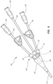
- FIGS. 2 and 3 show dual and triple-lumen catheter configurations, respectively, in contrast to the single-lumen configuration of FIG. 1 .
- the catheters 10 shown in FIGS. 2 and 3 each include sensor arrays 30 similar to that shown in FIG. 1 , including corresponding pressure sensors 32, ECG sensors 34, and PCBs 36.
- the electrical contacts 40 for electrical connection with electrical contacts 60 of the securement device 50 are also shown.
- each extension leg 18 of the catheters 10 in FIGS. 2 and 3 includes a corresponding one of the pressure sensors 32 such that pressure data may be sensed in each extension leg.
- more or fewer sensors can be employed for sensing physiological aspects of the patient and/or physical aspects of the catheter assembly including, for instance, lactic acid sensors, oxygen sensors, ultrasound componentry, GPS location sensors, temperature sensors, sizing sensors to measure intraluminal diameter, fluid velocity sensors, glucose meters, oxygen sensors, lactic acid sensors, cardiac output sensors, accelerometers, blood volumetric and cardiac output sensors, etc.
- FIG. 6 depicts the catheter 10 according to one embodiment, including three pressure sensors 30 in specified locations in the corresponding extension legs 18 and an ECG sensor 34 disposed in one extension leg, with each sensor operably connected to the PCB 36 disposed in the hub 16.
- FIG. 5 thus demonstrates that the number, type, and placement of the sensor(s) and PCB can vary from what has already been shown and described.
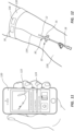
- FIG. 7 depicts details of the sensor-equipped catheter 10 according to one embodiment, wherein the hub 16 includes an ultrasound assembly 80 comprising upper and lower PCBs 82A and 82B configured to control ultrasound transducers 84A and 84B, respectively.
- the ultrasound transducers 84A and 84B can be used to ultrasonically evaluate the fluid passageway, or lumen 92, of the bifurcation hub 16 to determine the contents of the lumen, as shown in FIGS. 8A-8D .
- FIG. 8A shows that when air is present in the lumen 92, no ultrasound signal is present, as depicted in an ultrasound signal graph 90 of FIG. 8A .
- the ultrasound transducers 84A and 84B return a signal of a specified voltage consistent with the composition of fluid A, as seen by the graph 90 of FIG. 8B .
- the ultrasound transducer 84A and 84B return a signal of specified voltage consistent with the composition of fluid B, as seen in the graph 90 of FIG. 8C .
- the graph 90 of FIG. 8D shows that a varying voltage signal is detected by the ultrasound transducers 84A and 84B.
- the ultrasound transducers 84A and 84B coupled with the battery and PCB as discussed further above, can assist the user in determining the presence of particular substances in the lumen 92 of the hub 16, or the lumens of other catheter components, depending on placement of the ultrasound transducers. In another embodiment, only a single ultrasound transducer is employed.
- FIGS. 9A and 9B depict details of the sensor-equipped catheter 10 according to another embodiment, wherein the hub 16 includes a PCB 82 disposed therein and operably connected to a temperature sensor 100, such as a thermocouple in one embodiment, positioned so as to measure core body temperature via blood or other fluids present in the lumen 14 of the catheter.
- a temperature sensor 100 such as a thermocouple in one embodiment
- the temperature sensor 100 can be placed in proximity to the lumen 14 via a skiving or cavity 108 longitudinally defined in the catheter tube 12 and/or hub 16. Potting 106 can be used to fill the cavity 108 about the temperature sensor 100.
- the temperature sensor 100 includes a series 400 Model 401 thermistor available from Cole-Palmer Inc., Vernon Hills, IL.
- FIG. 10 shows that, in one embodiment, a variety of sensors can be included as part of the sensor array 30 within the hub 16 or other suitable location.
- the hub 16 includes disposed therein the pressure sensor 32, the PCB 36 (including a processor 36A and a wireless communication module 36B), upper and lower ultrasound transducers 84A and 84B, a temperature sensor 100, and an oxygen sensor 110.
- the various sensors are arranged as needed in proximity to the fluid passageway 26 of the hub 16 so as to sense the relevant parameters as detected in the fluid present in the fluid passageway. The particular arrangement of the sensors can vary from what is shown here.
- FIG. 11 shows that, in one embodiment a smartphone 100 can be the receipt location for wirelessly receiving data from one or more of the sensors of the sensor array, as discussed in the embodiments above.
- wireless modes by which the data can be transmitted include Bluetooth, Wi-Fi, radiofrequency, near-field communication (NFC), ANT, ZigBee, etc.
- NFC near-field communication
- ANT ZigBee
- Such data transmission can be relayed through a software-based application or other intermediary device. This enables a clinician to receive mobile updates and other sensor data 124 from the catheter 10 via a display 122 of the smartphone 120 (or by other mediums including sound, vibration, etc.) in order to be able to monitor the progress or condition of the patient.
- EPR patient electronic medical record
- patient monitoring apparatus other mobile devices including electronic tablets and laptop computers, an electronic storage location, a computer server, a nurse station, medical equipment such as a pump attached to the catheter, and a variety of other destinations. It is appreciated that devices, components, computers, etc. that are located at the receipt location can perform operations on the received data, including analysis, trending, alarm functions, etc.
- FIG. 12 depicts the catheter 10 according to another embodiment, wherein the catheter is shown inserted into an arm 128 of the patient such that a majority portion of the catheter tube 12 is disposed within the vasculature of the patient.
- the hub 16, including one or more sensors, is also shown operably connected to an auxiliary device, such as an armband 130, placed around the patient arm 128 via a connecting wire 134.
- the armband 130 is placed in proximity to the external portion of the catheter 10 in the present embodiment, though its location and particular shape, size, configuration, and body attachment scheme can vary in other embodiments.
- the armband 130 includes various components to work in concert with the sensor(s) of the catheter 10 via the connection wire 134, including the PCB 36 and a wireless communication module 136 (which in other embodiments is included with the PCB).
- Sensor data detected by the sensor(s) of the catheter 10 can be forwarded from the catheter 10 to the components of the armband 130 via the connecting wire 134, where the data can be processed ( e.g., by the PCB 36) and/or transmitted to a remote location ( e.g., by the wireless communication module 136).
- the operable connection between the catheter 10 and the armband 130 is a wireless connection as well.
- Placement of the PCB 36 and the wireless communication module 136 on the armband 130 frees up space on the catheter and may prevent the need for replacing relatively expensive components when the catheter 10 itself is periodically replaced with a new catheter.
- the armband 130 can be simply connected to the new catheter, and the PCB 36 and wireless communication module 136 can begin to function with the new catheter as they did with the previous catheter.
- various other components can also be included on the armband 130, including a battery for powering the sensor(s) included on the catheter, additional sensors including an ECG sensor, etc.
- the armband 130 is representative of other wearable and non-wearable auxiliary devices that can be operably connected to the sensor(s) of the catheter 10 in order to facilitate their operation.
- the components included on the armband/auxiliary device can be replaceable/reusable, in one embodiment.
- the PCB, battery, and/or wireless communication module can be included on the catheter securement device.
- the above-described components can be included on a platform that is removably attachable to the armband.
- the armband or similar component includes a disposable shield to isolate it from the patient and/or to provide isolation from contaminants.
- FIG. 13 shows a pressure graph 140 including a pressure curve 142 that depicts the level of pressure over time in the catheter tube lumen 14 as sensed by the pressure sensor 32, such as in the pressure sensor configuration of FIG.
- the pressure curve 142 includes various pressure peaks 144 that are caused by the user pulsing the syringe with moments of additional pressure. This is performed so as to clear any minor obstructions that may have formed within the catheter tube lumen 14 or in other areas of the catheter fluid path.
- an occlusion is present at the distal end 12B of the catheter tube and/or within the lumen 14 ( see occlusion 178 in FIG. 15 for example)
- the pressure curve 142 will be elevated ( i.e., shifted vertically upward along the pressure y-axis) or widened ( i.e., lengthened along the time x-axis).
- Detection of an elevated pressure within the catheter fluid path by the pressure sensor 32 can alert the user to a possible occlusion such that corrective measures can be taken.
- data storage in a memory location located on the catheter 10 with the PCB 36 or remotely located in a patient electronic medical record (or other remote storage location) can be employed to measure the catheter flushing pressure over time so as to detect pressure changes over time. This data comparison over time can be performed for any one of the sensors located on the catheter 10, as may be appreciated.
- the data sensed by the sensors and stored in a memory location can be used for a variety of other uses as well, including historical trends, etc...
- FIG. 14 depicts various details of a pressure-sensing syringe 150 according to one embodiment, including a housing 152 that defines a cavity 154 with a distal end fluid outlet 156.
- a plunger 158 is disposed within the cavity 154 and is attached to a spring 160, initially disposed in a compressed state and releasable by a release button 162 disposed on a proximal end of the syringe 150.
- a known quantity of 0.9% normal saline 164 or other suitable liquid is disposed in the cavity distal to the plunger 158 such that the saline exits the fluid outlet 156 when the spring 160 is actuated by the release button 162.
- the saline 164 ejected by the syringe 150 is injected into the extension leg 18 - then through the hub 16 and lumen 14 of the catheter tube - when the syringe is operably attached to the corresponding luer connector 20.
- a pressure sensor 166 is included at the fluid outlet 166 to measure the pressure of the known quantity of saline 164 as it exits the fluid outlet 156 and enters the catheter 10 to which the syringe 150 is connected.
- a processor unit 170 and a display/control unit 172 are included to measure and calculate (such as via the equations described further above) the pressure present as the saline 164 is ejected by the plunger 158 through the fluid outlet.
- Further calculations can be performed by the processor unit 170 to determine the hydraulic resistance of the injection, thus yielding the amount of occlusion present in the fluid path of the catheter 10, using the known volume of injected saline 164, the injection pressure as measured by the pressure sensor 166, and the amount of time needed for injection of all the saline to occur.
- the user can input the size of the catheter tube lumen 14 and the length thereof via the display/control unit 172.
- results describing the amount of any occlusion present in the catheter fluid path can be depicted on the display/control unit 172 or wirelessly transmitted to a receipt location via a wireless communication module included with the processor unit 170, for instance. Corrective measured can then be taken by the user, if needed.
- historical pressure/occlusion data can be stored by a memory location of the processor unit 170, for instance, for call-up and depiction by the display/control unit 172, in one embodiment.
- the plunger 158 of the syringe 150 is manually depressible by the user, thus obviating the need for the spring 160, or can be a pressurized gas source to push the plunger, etc.
- the location of the pressure sensor 166 can also vary from what is shown and described herein.
- the pressure sensor 32 can be used to determine when the catheter tub 12 has been malpositioned within the vasculature by sensing pressure differences between expected values for a proper placement and actual sensed values as detected by the pressure sensor. When this situation occurs, proper steps to correct the malposition can be taken.
- the pressure sensor 32 and the electrical (ECG) sensor 34 can work in concert to detect catheter malposition based on venous pressure readings and ECG signal analysis.
- FIG. 15 depicts various details of the catheter 10 that includes the ability to detect occlusions, such as a partial occlusion 178 shown at the distal end 12B of the catheter tube 12, according to one embodiment.
- the catheter 10 includes a pressure detection module 180 operably attached to the luer connector 20 of the catheter 10.
- a syringe 182 is attached to a proximal end of the pressure detection module 180 so as to provide an injection of saline or other suitable fluid through a flow lumen 184 of the pressure detection module 182 and into the extension leg 18 to flow through the catheter 10.
- the pressure detection module 180 includes a pressure indicator 188 in fluid communication with the flow lumen 184.
- the pressure indicator 188 is configured to extend an indicator piece outward when a predetermined pressure is encountered in the flow lumen 184 of the pressure detection module.
- the pressure detection module 180 is a separate component attachable to the catheter 10; in other embodiments the pressure detection module is integrally formed with the catheter.
- FIG. 16 depicts possible locations for sensors of the sensor array 30 in the catheter tube 12.
- various sensors 200 of the sensor array 30 are disposed proximate the distal end 12B of the catheter tube 12, together with the pressure sensor 32 disposed proximally to the other sensors.
- FIG. 16 further shows that a connection wire 192 extends along a central portion of the catheter tube, e.g ., within a septum separating the lumens 14 from one another, to power the sensors 200 of the sensor array 30.
- the connection wire 192 can be disposed in a dedicated lumen extending the length of the catheter tube. Note that placement of the sensor(s) a distance proximal to the catheter tube distal end 12B, such as the pressure sensor 32 here, enables the catheter tube 12 to be distally trimmable.
- FIG. 17 depicts another configuration for including a sensor 200 in the catheter tube 12, wherein the sensor 200 is disposed in the wall of the catheter tube 12 within a skive cut 198 longitudinally defined in the wall. Potting 204, such as a thermally conductive epoxy, polyurethane, or RTV potting, is included to cover the sensor 200.
- the sensor 200 includes a glucose sensor for sensing blood glucose levels and is not potted such that the glucose sensor has direct contact with the blood. These and other possible sensor locations are therefore contemplated.
- FIG. 18 depicts another configuration for including a sensor in the catheter tube 12, wherein the sensor 200 is disposed on an inner surface of one of the lumens 14 of the catheter tube 12 proximate the distal end 12B thereof. Potting 204 can be included to insulate and cover the sensor 200 as needed. In one embodiment, the potting 200 protects the sensor 200 from exposure to liquids while enabling heat to be transmitted therethrough.
- FIG. 18 further shows that wire-based electrodes 210 can be disposed in the wall of the catheter tube 12 proximate the distal end 12B of the catheter tube 12 so as to be exposed on an outer surface thereof.
- the sensors 210 can be formed as concentrically disposed sensors that can be employed to make volumetric measurements to determine the size of the vessel in which the catheter tube is disposed, thus assisting the user in determining a possible malposition of the catheter tube in an undesired vessel. These and other possible sensor configurations are therefore contemplated.
- FIG. 19 depicts various details of a flush sensor 222 for detecting when the desired periodic flushing of the catheter 10 with a fluid has occurred, also referred to herein as a flush state of the catheter tube 12.
- the flush sensor 222 is disposed within a cavity 220 of the luer connector of the catheter extension leg 18, though other locations can be employed for the sensor.
- the flush sensor 222 also referred to herein as a detection module, includes a lever 224 biased to an extended position by a spring 226, as shown.
- the flush sensor 222 is operably connected to a processor of a PCB (such as the PCB 36 shown in FIG. 10 ) or other suitable component (disposed within the luer connector 20, for instance) to govern its operation and process its sensed data.
- a PCB such as the PCB 36 shown in FIG. 10
- suitable component disposed within the luer connector 20, for instance
- the lever 224 of the flush sensor 222 is depressed, which causes a signal to be sent to the processor indicating that a flushing procedure is occurring.
- the time of flushing or other data relating to the flushing procedure can be noted, stored or used by the processor, or wirelessly transmitted to a receipt location in a manner similar to that discussed further above.
- the flush sensor 222 and the processor of the PCB 36 are referred to as a flush sensor assembly, though it is appreciated that the assembly can include additional components.
- an electrical sensor can be employed as the flush sensor, wherein the electrical sensor includes a circuit that is broken each time a component is inserted into the connector 20. Breaking of the circuit can reset a timer circuit to measure the next period until the flush sensor is again activated.
- the catheter 10 be flushed at least once every 12 hours.
- a timer circuit in the processor is re-set to begin counting time to measure the next time period until the flush sensor 222 is again depressed to indicate a new flushing procedure.
- FIG. 20 shows that a light array 230, such as a collection of a red LED light, yellow LED light, and green LED light, can be included on a surface of the luer connector 20 to visually indicate the flushing status of the catheter 10, in one embodiment: a green light indicates less than 10 hours have elapsed since the last flushing procedure was detected; a yellow light indicates more than 10 hours but less than 12 hours have elapsed since the last flushing procedure; a red light indicates that more than 12 hours have elapsed since the last flushing procedure.
- the processor governs the operation of the light array and it is understood that the lights can vary in number size, location, purpose, indicated elapsed time, etc. Further, it is appreciated that other types of sensors, including sensors that detect the presence of liquid within the luer connector cavity 220, can also be employed to detect flushing procedures.
- the light array 230 can be used as follows: the green light flashes after an acceptable flushing procedure has been performed; the red light blinks after a non-acceptable or incomplete flushing procedure has occurred; the yellow light blinks or is turned on to indicate a possible occlusion present in the catheter tube 12.
- the yellow light (or other light) can be lit to serve as a reminder to flush the catheter10.
- the luer connector 20 or other portion of the catheter 10 can include a push button (or other user-activated component) that can be depressed at the time of catheter flushing, thus re-setting the timer circuit.
- a counting circuit can also be included to count the number of times the connector 20 or other component is accessed.
- FIG. 21 shows that the light array 230 can be disposed in other locations on the catheter 10, including in this embodiment disposal on the hub 16. These and other possible locations, such as the catheter tube or extension legs, or the armband 130 of FIG. 12 for example, are therefore contemplated.
- the light array can be employed to alert the user to other sensed conditions, including elevated body temperature/fever, onset of sepsis ( see further below), catheter occlusion, low blood oxygen levels, etc.
- other indicia can be employed, in addition to lights, to alert the user with respect to the sensor data, including sound, vibration, etc. either on the catheter itself or at the remote receipt location to where the data is wirelessly transmitted.
- flush sensor 222 can be included in other areas as well, including a needleless connector that is configured to operably attach to the luer connector, for instance.
- the pressure sensor 32 can be used - alone or in concert with the flush sensor 222 described above - to detect and/or characterize flushing procedures.
- the flush sensor 222 can be used to detect a flushing procedure, while the pressure sensor 32 can sense the amount of pressure present during the flushing procedure, thus detecting possible occlusions.
- the pressure sensor 32 can be used to determine flushing frequency of the catheter 10, flushing technique, flushing time, number of times of catheter access, time expired since last catheter access, etc., by measuring pressure within the lumen 14 of the catheter as a function of time, using timer circuitry included on the PCB 36, for instance.
- Such sensor data can be stored by a memory location located on the PCB 36, for instance, or transmitted to another local or remote receipt location, as has been described. Processing to determine such monitoring can be performed by a processor included on the PCB 36 or remotely.
- sensor data from catheter sensors can be employed to detect patient conditions, such as sepsis.
- patient conditions such as sepsis.
- respiratory rate, heart rate, and body temperature can be sensed via the pressure sensor 32 and the core body temperature sensor 100 included with the catheter 10, such as in the configuration shown in FIG. 10 .
- These three parameters comprise three of four parameters that are typically employed to determine the onset of sepsis. As such, monitoring of these parameters via the catheter 10 as described herein can be used to prevent detect and ameliorate complications from sepsis, in one embodiment.
- FIG. 22 depicts a sensor-based catheter assembly according to another embodiment.
- the catheter 10 is shown with its catheter tube 12 disposed within the vasculature of the patient and the two luer connectors 20 operably connected to supply lines 240 configured to both provide fluid to and remove fluid from the lumens of the catheter.
- a pump unit 250 is included to enable fluid movement through the supply lines 240.
- a saline fluid drip assembly 252 is also included to provide fluid to the pump unit for movement through the supply lines, if needed or desired.
- a syringe such as the syringe 182, is included to provide an additional fluid inlet in a corresponding one of the supply lines 240.
- FIG. 23 depicts further details of the pump unit 250 of FIG. 22 , including a fluid inlet 256A and a fluid outlet 256B that are configured to operably connect with the corresponding supply lines 240 ( FIG. 22 ) to bring blood or other fluid from within the patient vasculature via the catheter 10 (through the fluid inlet 256A) to the pump unit 250 and to return the fluid to the patient vasculature (through the fluid outlet 256B) via the catheter.
- a pump 258 is included in the pump unit 250 to cause the movement of the fluid.
- various input ports 260 are included on the pump unit 250 in fluid communication with the fluid inlet 256A to enable additional fluids to be input, including heparin, saline, arterial input, etc.
- One or more sensors 200 are also included in the pump unit 250 and arranged so as to measure one or more physiological aspects of the patient blood. Examples of such sensors include a glucose meter, oxygen sensor, lactic acid sensor, cardiac output sensor, etc.
- the location of the sensors 200 can vary from what is shown here. Disposal of the sensors 200 in the pump unit 250 as opposed to the on the catheter 10 itself enables sensors of relatively greater size to be employed without unduly increasing the size of the catheter.
- the described embodiments are to be considered in all respects only as illustrative, not restrictive. The scope of the invention is, therefore, indicated by the appended claims rather than by the foregoing description.
Landscapes
- Health & Medical Sciences (AREA)
- Life Sciences & Earth Sciences (AREA)
- Engineering & Computer Science (AREA)
- Biomedical Technology (AREA)
- Public Health (AREA)
- General Health & Medical Sciences (AREA)
- Heart & Thoracic Surgery (AREA)
- Animal Behavior & Ethology (AREA)
- Veterinary Medicine (AREA)
- Biophysics (AREA)
- Medical Informatics (AREA)
- Physics & Mathematics (AREA)
- Pathology (AREA)
- Molecular Biology (AREA)
- Surgery (AREA)
- Cardiology (AREA)
- Physiology (AREA)
- Pulmonology (AREA)
- Hematology (AREA)
- Anesthesiology (AREA)
- Computer Networks & Wireless Communication (AREA)
- Nuclear Medicine, Radiotherapy & Molecular Imaging (AREA)
- Radiology & Medical Imaging (AREA)
- Primary Health Care (AREA)
- General Business, Economics & Management (AREA)
- Epidemiology (AREA)
- Business, Economics & Management (AREA)
- Vascular Medicine (AREA)
- Optics & Photonics (AREA)
- Immunology (AREA)
- Emergency Medicine (AREA)
- Measuring And Recording Apparatus For Diagnosis (AREA)
- Media Introduction/Drainage Providing Device (AREA)
- Measuring Pulse, Heart Rate, Blood Pressure Or Blood Flow (AREA)
- Measurement Of The Respiration, Hearing Ability, Form, And Blood Characteristics Of Living Organisms (AREA)
Claims (15)
- Ensemble comprenant un ensemble de cathéter (10) pour une insertion dans un corps d'un patient, l'ensemble de cathéter comprenant :un tube de cathéter allongé (12) définissant au moins une lumière (14) s'étendant entre une extrémité proximale et une extrémité distale ;un moyeu de bifurcation (16) fonctionnellement fixé au tube de cathéter ; etune patte d'extension (18) fonctionnellement fixée au moyeu de bifurcation, les moyeu de bifurcation et patte d'extension définissant au moins un passage de fluide en communication fluidique avec la au moins une lumière du tube de cathéter ; au moins un capteur inclus avec au moins un parmi le moyeu de bifurcation, la patte d'extension, et une extrémité proximale du tube de cathéter, le au moins un capteur étant configuré pour détecter au moins un parmi un aspect physiologique du patient et un aspect physique de l'ensemble de cathéter ;l'ensemble comprenant en outre :
un dispositif de maintien configuré pour être placé sur la peau du patient et se raccorder fonctionnellement avec et maintenir en place l'ensemble de cathéter, le dispositif de maintien comprenant un module de communication (136) configuré pour transmettre sans fil des données captées par le au moins un capteur à un emplacement de réception. - Ensemble de cathéter tel que défini dans la revendication 1, dans lequel le au moins un capteur est disposé dans le moyeu de bifurcation.
- Ensemble de cathéter tel que défini dans la revendication 1, dans lequel le au moins un capteur inclut un capteur de pression, un capteur d'oxygène, un capteur de température, et un transducteur à ultrasons, un capteur de glucose, et un capteur électrique configuré pour détecter des signaux ECG.
- Ensemble de cathéter tel que défini dans la revendication 1, dans lequel l'ensemble de cathéter comprend une pluralité de capteurs, au moins un des capteurs incluant un capteur électrique configuré pour détecter un signal ECG d'un coeur d'un patient.
- Ensemble de cathéter tel que défini dans la revendication 4, dans lequel le capteur électrique est disposé dans une paroi du tube de cathéter à proximité de l'extrémité distale du tube de cathéter.
- Ensemble de cathéter tel que défini dans la revendication 1, dans lequel le au moins un capteur est configuré pour détecter le moment auquel l'ensemble de cathéter est rincé avec un fluide.
- Ensemble de cathéter tel que défini dans la revendication 6, dans lequel le au moins un capteur inclut un capteur de rinçage qui est configuré pour être activé lorsqu'un composant est fonctionnellement raccordé à l'ensemble de cathéter.
- Ensemble de cathéter tel que défini dans la revendication 7, dans lequel le capteur de rinçage inclut un levier qui est configuré pour être déplacé lorsque le composant est fonctionnellement raccordé à l'ensemble de cathéter.
- Ensemble de cathéter tel que défini dans la revendication 8, dans lequel le capteur de rinçage est inclus dans au moins un parmi un raccord Luer et un raccord sans aiguille inclus avec l'ensemble de cathéter, et, facultativement, comprenant en outre un capteur de pression qui est configuré pour fonctionner avec le capteur de rinçage pour détecter le moment auquel l'ensemble de cathéter est rincé avec un fluide.
- Ensemble de cathéter tel que défini dans la revendication 1 :
comprenant en outre au moins une lumière (230) disposée sur l'ensemble de cathéter, la lumière étant configurée pour fonctionner conjointement avec le au moins un capteur pour alerter un utilisateur quant à un aspect du au moins un capteur. - Ensemble cathéter selon la revendication 1, comprenant en outre un capteur de pression et un capteur de température, le capteur de pression et le capteur de température étant configurés pour capter un rythme respiratoire, un rythme cardiaque, et une température corporelle du patient afin de déterminer si une condition de sepsis est présente.
- Ensemble cathéter selon la revendication 1, comprenant en outre une batterie (62) configurée pour alimenter au moins un parmi le au moins un capteur et une carte de circuit imprimé inclus avec l'ensemble de cathéter, dans lequel la batterie est incluse dans le dispositif de maintien.
- Ensemble cathéter selon la revendication 1, dans lequel le dispositif de maintien inclut des premier et second contacts électriques (60) qui sont configurés pour se raccorder fonctionnellement avec des contacts électriques correspondants de l'ensemble de cathéter.
- Ensemble de cathéter tel que défini dans la revendication 1, comprenant en outre :
un dispositif auxiliaire, le dispositif auxiliaire étant fonctionnellement fixé au au moins un capteur de l'ensemble de cathéter pour faciliter leur fonctionnement. - Ensemble de cathéter tel que défini dans la revendication 14 :dans lequel le dispositif auxiliaire est configuré pour être porté sur le corps ou les vêtements du patient ; ou
dans lequel le dispositif auxiliaire inclut au moins un composant amovible ou réutilisable ; oudans lequel le dispositif auxiliaire inclut une carte de circuit imprimé et une batterie, la carte de circuit imprimé et la batterie étant fonctionnellement raccordées au au moins un capteur de l'ensemble de cathéter par l'intermédiaire d'un fil de raccordement ; oudans lequel le dispositif auxiliaire inclut un module de communication sans fil ; ou dans lequel le dispositif auxiliaire inclut un brassard.
Applications Claiming Priority (2)
| Application Number | Priority Date | Filing Date | Title |
|---|---|---|---|
| US201562233184P | 2015-09-25 | 2015-09-25 | |
| PCT/US2016/053566 WO2017053882A1 (fr) | 2015-09-25 | 2016-09-23 | Ensemble de cathéter comprenant des capacités de surveillance |
Publications (4)
| Publication Number | Publication Date |
|---|---|
| EP3346913A1 EP3346913A1 (fr) | 2018-07-18 |
| EP3346913A4 EP3346913A4 (fr) | 2019-01-16 |
| EP3346913B1 true EP3346913B1 (fr) | 2025-04-23 |
| EP3346913C0 EP3346913C0 (fr) | 2025-04-23 |
Family
ID=58387433
Family Applications (1)
| Application Number | Title | Priority Date | Filing Date |
|---|---|---|---|
| EP16849804.6A Active EP3346913B1 (fr) | 2015-09-25 | 2016-09-23 | Ensemble de cathéter comprenant des capacités de surveillance |
Country Status (6)
| Country | Link |
|---|---|
| US (4) | US10433790B2 (fr) |
| EP (1) | EP3346913B1 (fr) |
| JP (2) | JP7091240B2 (fr) |
| CN (3) | CN113598720B (fr) |
| AU (3) | AU2016326714B2 (fr) |
| WO (1) | WO2017053882A1 (fr) |
Families Citing this family (39)
| Publication number | Priority date | Publication date | Assignee | Title |
|---|---|---|---|---|
| JP6491652B2 (ja) | 2013-10-16 | 2019-03-27 | シー・アール・バード・インコーポレーテッドC R Bard Incorporated | 一体化された指示を有するカテーテル挿入トレー |
| EP3346913B1 (fr) | 2015-09-25 | 2025-04-23 | C. R. Bard, Inc. | Ensemble de cathéter comprenant des capacités de surveillance |
| WO2018125845A1 (fr) | 2016-12-27 | 2018-07-05 | Vasonics, Llc | Dispositif de rétention de cathéter |
| MX2019011562A (es) | 2017-03-31 | 2019-11-18 | Bard Inc C R | Sistemas de bandeja de insercion de cateteres y metodos de los mismos. |
| US11660032B2 (en) | 2017-09-07 | 2023-05-30 | SWSA Medical Ventures, LLC | Catheter assemblies, oxygen-sensing assemblies, and related methods |
| US11395616B2 (en) | 2017-09-07 | 2022-07-26 | WSA Medical Ventures, LLC | Catheter assemblies, oxygen-sensing assemblies, and related methods |
| CA3097891A1 (fr) | 2018-04-24 | 2019-10-31 | C.R. Bard, Inc. | Emballages de catheterisation et procedes associes |
| JP2021525586A (ja) * | 2018-05-29 | 2021-09-27 | ベー・ブラウン・メルズンゲン・アクチエンゲゼルシャフトB.Braun Melsungen Aktiengesellschaft | センサを用いた末梢静脈カテーテルアセンブリ及び関連する方法 |
| US11612715B2 (en) | 2018-06-20 | 2023-03-28 | C. R. Bard, Inc. | Urinary catheter-insertion kits with integrated instructions for use and methods thereof |
| EP3817785A4 (fr) * | 2018-07-02 | 2022-07-20 | C. R. Bard, Inc. | Ensembles cathéters antimicrobiens et procédés associés |
| US12453531B2 (en) * | 2018-07-10 | 2025-10-28 | Koninklijke Philips N.V. | Electrical wire connection in ultrasound imaging devices, systems, and methods |
| US12419523B2 (en) | 2018-07-13 | 2025-09-23 | Semitec Corporation | Sensor device, catheter, and system provided with sensor device |
| US11096582B2 (en) * | 2018-11-20 | 2021-08-24 | Veris Health Inc. | Vascular access devices, systems, and methods for monitoring patient health |
| CN109621158B (zh) * | 2018-11-30 | 2021-06-15 | 3M创新有限公司 | 导管固定组件 |
| US11589873B2 (en) * | 2018-12-31 | 2023-02-28 | Biosense Webster (Israel) Ltd. | Occlusion detection by pressure measurement |
| US11839742B2 (en) * | 2019-01-18 | 2023-12-12 | Becton, Dickinson And Company | Intravenous device with integrated sensors |
| EP3921014B1 (fr) * | 2019-02-04 | 2024-06-12 | Becton, Dickinson and Company | Système, procédé et produit de surveillance d'événements |
| US20200305742A1 (en) * | 2019-03-27 | 2020-10-01 | Kamran Ghodsian | System and method for child-birth monitoring and assistance |
| US12083290B2 (en) * | 2019-04-08 | 2024-09-10 | Becton, Dickinson And Company | Catheter assembly clamp having an acoustic sensor |
| CN113727656A (zh) * | 2019-05-17 | 2021-11-30 | 波士顿科学国际有限公司 | 为径向超声端口和冲洗端口提供可调整机构的设备 |
| KR20220024485A (ko) * | 2019-06-11 | 2022-03-03 | 바드 액세스 시스템즈, 인크. | 펌프, 혈관 접근 장치, 및 고정 장치를 포함하는 정맥 시스템, 그리고 그 방법(intravenous system including pump, vascular access device and securement device and methods thereof) |
| US20220386961A1 (en) * | 2019-11-18 | 2022-12-08 | Veris Health Inc. | Vascular access devices, systems, and methods for monitoring patient health |
| EP4069348B1 (fr) * | 2020-01-03 | 2024-06-12 | Bard Access Systems, Inc. | Systèmes de cicatrisation |
| MX2022008297A (es) * | 2020-01-07 | 2022-08-08 | Bard Access Systems Inc | Sistemas y metodo de diagnostico que incluyen dispositivo vasculares de deteccion de temperatura. |
| CN111265222A (zh) * | 2020-03-24 | 2020-06-12 | 孙孟良 | 一种icu患者非计划性拔管预警系统 |
| US12042607B2 (en) | 2020-04-23 | 2024-07-23 | Covidien Lp | Catheter with valves |
| US11717642B2 (en) | 2020-04-24 | 2023-08-08 | Covidien Lp | Catheter including one or more sensors |
| US11744498B2 (en) | 2020-07-17 | 2023-09-05 | Covidien Lp | Catheter system |
| WO2022055956A1 (fr) * | 2020-09-09 | 2022-03-17 | Becton, Dickinson And Company | Dispositif et système de pansement et/ou de fixation de cathéter, procédé et produit de détection de l'état d'un site intraveineux |
| US20220126063A1 (en) * | 2020-10-27 | 2022-04-28 | Boston Scientific Scimed, Inc. | Medical device with printed battery |
| US11931066B2 (en) | 2021-02-25 | 2024-03-19 | Avent, Inc. | Directly connected smart invasive medical device assembly |
| WO2022263549A2 (fr) * | 2021-06-17 | 2022-12-22 | B. Braun Melsungen Ag | Système de cathéter intraveineux intelligent |
| CN113842517B (zh) * | 2021-10-11 | 2022-03-29 | 四川大学 | 用于液体灌注的智能调控方法 |
| JP7774723B2 (ja) * | 2021-10-14 | 2025-11-21 | バード・ペリフェラル・バスキュラー・インコーポレーテッド | 血管アクセスデバイス配置用の多機能アダプタ |
| EP4472924A1 (fr) | 2022-02-25 | 2024-12-11 | Bard Access Systems, Inc. | Méthodes de transfert de graphène vers des substrats et empilements et stratifiés lithographiques associés |
| CN115153747A (zh) * | 2022-07-19 | 2022-10-11 | 上海诺英医疗器械有限公司 | 数据监测系统 |
| US20240180491A1 (en) * | 2022-12-02 | 2024-06-06 | Bard Access Systems, Inc. | Cut-to-Length Sensing Catheters and Methods Thereof |
| CN120569240A (zh) * | 2023-01-03 | 2025-08-29 | 贝克顿·迪金森公司 | 用于医疗装置中消毒的认证、识别和检测的系统 |
| WO2025173016A1 (fr) * | 2024-02-13 | 2025-08-21 | Iffat Rahman | Dispositif d'aide à la canulation intraveineuse pour les professionnels de santé |
Family Cites Families (216)
| Publication number | Priority date | Publication date | Assignee | Title |
|---|---|---|---|---|
| US6241704B1 (en) | 1901-11-22 | 2001-06-05 | Sims Deltec, Inc. | Drug pump systems and methods |
| US4370983A (en) | 1971-01-20 | 1983-02-01 | Lichtenstein Eric Stefan | Computer-control medical care system |
| US3739943A (en) | 1971-02-04 | 1973-06-19 | Sherwood Medical Ind Inc | Infusion system |
| US3809871A (en) | 1972-12-01 | 1974-05-07 | Nasa | Programmable physiological infusion |
| US3985133A (en) | 1974-05-28 | 1976-10-12 | Imed Corporation | IV pump |
| US4078562A (en) | 1976-08-16 | 1978-03-14 | Diana W. Friedman | Infusion pump with feedback control |
| US4207871A (en) | 1978-06-07 | 1980-06-17 | Imed Corporation | System for controlling the flow of intravenous fluids to a patient |
| US4373527B1 (en) | 1979-04-27 | 1995-06-27 | Univ Johns Hopkins | Implantable programmable medication infusion system |
| US4533346A (en) | 1979-06-26 | 1985-08-06 | Pharmacontrol Corporation | System for automatic feedback-controlled administration of drugs |
| DE3018641C2 (de) | 1980-05-16 | 1986-05-28 | Hans 8228 Freilassing Rodler | Automatische Infusionspumpe |
| US4346705A (en) | 1980-10-09 | 1982-08-31 | Baxter Travenol Laboratories, Inc. | Metering apparatus having rate compensation circuit |
| FR2512665A1 (fr) | 1981-09-12 | 1983-03-18 | Wolf Gmbh Richard | Catheter pour la mesure de la pression intra-uretrale |
| US4474309A (en) | 1981-10-22 | 1984-10-02 | Oximetrix, Inc. | Stepping motor control procedure for achieving variable rate, quasi-continuous fluid infusion |
| US4613325A (en) | 1982-07-19 | 1986-09-23 | Abrams Lawrence M | Flow rate sensing device |
| CA1201999A (fr) | 1982-08-03 | 1986-03-18 | Peter G. Wheeldon | Methode et dispositif de regulation du debit d'un fluide |
| US4507974A (en) | 1983-04-21 | 1985-04-02 | The Board Of Trustees Of The Leland Stanford Jr. University | Method and apparatus for measuring flow |
| US4530696A (en) | 1983-06-13 | 1985-07-23 | Institute Of Critical Care Medicine | Monitor for intravenous injection system for detecting occlusion and/or infiltration |
| US4573968A (en) | 1983-08-16 | 1986-03-04 | Ivac Corporation | Infusion and blood chemistry monitoring system |
| US4497324A (en) | 1983-10-03 | 1985-02-05 | American Hospital Supply Corporation | Temperature monitoring catheter |
| US5100380A (en) | 1984-02-08 | 1992-03-31 | Abbott Laboratories | Remotely programmable infusion system |
| US4604093A (en) | 1984-06-12 | 1986-08-05 | I-Flow Corporation | Apparatus and method for administering multiple fluid infusions |
| US4756706A (en) | 1985-01-23 | 1988-07-12 | American Hospital Supply Corporation | Centrally managed modular infusion pump system |
| US4747828A (en) | 1986-12-09 | 1988-05-31 | Fisher Scientific Group | IV fluid line occlusion detector |
| US5024668A (en) | 1987-01-20 | 1991-06-18 | Rocky Mountain Research, Inc. | Retrograde perfusion system, components and method |
| US5195960A (en) | 1987-04-27 | 1993-03-23 | Site Microsurgical Systems, Inc. | Disposable vacuum/peristaltic pump cassette system |
| US4838856A (en) | 1987-07-02 | 1989-06-13 | Truckee Meadows Research & Development | Fluid infusion flow control system |
| US4796641A (en) | 1987-07-06 | 1989-01-10 | Data Sciences, Inc. | Device and method for chronic in-vivo measurement of internal body pressure |
| US4785823A (en) | 1987-07-21 | 1988-11-22 | Robert F. Shaw | Methods and apparatus for performing in vivo blood thermodilution procedures |
| US4809710A (en) | 1988-01-11 | 1989-03-07 | Williamson Jeffrey L | Multilumen manometer catheter |
| JP2683272B2 (ja) * | 1988-03-04 | 1997-11-26 | スペクトラメッド インコーポレーテッド | 血圧測定カテーテル用改良形フラッシュバルブ組立体 |
| US4979940A (en) | 1988-03-08 | 1990-12-25 | Baxter International Inc. | Infusion system, methodology, and algorithm for identifying patient-induced pressure artifacts |
| US4846191A (en) | 1988-05-27 | 1989-07-11 | Data Sciences, Inc. | Device for chronic measurement of internal body pressure |
| US5000190A (en) | 1988-06-22 | 1991-03-19 | The Cleveland Clinic Foundation | Continuous cardiac output by impedance measurements in the heart |
| US5108364A (en) | 1989-02-16 | 1992-04-28 | Sumitomo Bakelte Company Limited | Monitoring catheter for medical use |
| US5000664A (en) | 1989-06-07 | 1991-03-19 | Abbott Laboratories | Apparatus and method to test for valve leakage in a pump assembly |
| US5116312A (en) | 1989-11-03 | 1992-05-26 | The Uab Research Foundation | Method and apparatus for automatic autotransfusion |
| US4981467A (en) | 1990-02-27 | 1991-01-01 | Baxter International Inc. | Apparatus and method for the detection of air in fluid delivery systems |
| US5078683A (en) | 1990-05-04 | 1992-01-07 | Block Medical, Inc. | Programmable infusion system |
| US5171301A (en) | 1991-10-15 | 1992-12-15 | Imed Corporation | Multiple mini-pump infusion system |
| US5755683A (en) | 1995-06-07 | 1998-05-26 | Deka Products Limited Partnership | Stopcock valve |
| US5275169A (en) | 1992-01-15 | 1994-01-04 | Innovation Associates | Apparatus and method for determining physiologic characteristics of body lumens |
| US5195967A (en) | 1992-02-18 | 1993-03-23 | Nakao Naomi L | Anticlotting device and method for use with IV catheters |
| EP0655107B1 (fr) | 1992-06-09 | 2002-10-16 | Baxter International Inc. | Pompe a perfusion programmable a tubulure interchangeable |
| ATE198159T1 (de) | 1992-10-15 | 2001-01-15 | Gen Hospital Corp | Infusionspumpe mit elektronisch ladbarer medikamentenbibliothek |
| US5299571A (en) | 1993-01-22 | 1994-04-05 | Eli Lilly And Company | Apparatus and method for implantation of sensors |
| JPH0715051U (ja) | 1993-08-24 | 1995-03-14 | トノクラ医科工業株式会社 | カテ−テル |
| US5902238A (en) * | 1993-09-14 | 1999-05-11 | University Of Washington | Medical tube and apparatus for locating the same in the body of a patient |
| US5385563A (en) | 1993-09-14 | 1995-01-31 | The Kendall Company | Urodynamic catheter |
| US5431627A (en) | 1993-11-12 | 1995-07-11 | Abbott Laboratories | Cassette identification system for use with a multi-program drug infusion pump |
| US5569186A (en) | 1994-04-25 | 1996-10-29 | Minimed Inc. | Closed loop infusion pump system with removable glucose sensor |
| US6757630B2 (en) | 1994-08-19 | 2004-06-29 | Mediq/Prn Life Support Services, Inc. | Integrated systems for testing and certifying the physical, functional, and electrical performance of IV pumps |
| US6213972B1 (en) | 1994-09-13 | 2001-04-10 | Alaris Medical Systems, Inc. | Fluid flow resistance monitoring system |
| US5522399A (en) * | 1994-09-26 | 1996-06-04 | Wilk; Peter J. | Catheterization device and associated assembly |
| US5685844A (en) | 1995-01-06 | 1997-11-11 | Abbott Laboratories | Medicinal fluid pump having multiple stored protocols |
| EP0831946A4 (fr) | 1995-02-07 | 1999-09-22 | Gensia Inc | Systeme d'administration des medicaments a retrocontrole |
| US8082018B2 (en) | 1995-04-20 | 2011-12-20 | Acist Medical Systems, Inc. | System and method for multiple injection procedures on heart vessels |
| US5772635A (en) | 1995-05-15 | 1998-06-30 | Alaris Medical Systems, Inc. | Automated infusion system with dose rate calculator |
| US5676145A (en) | 1995-08-21 | 1997-10-14 | University Of Maryland At Baltimore | Cerebral hemodynamic monitoring system |
| DE29601310U1 (de) | 1996-01-26 | 1997-06-05 | B. Braun Melsungen Ag, 34212 Melsungen | Katheterbesteck mit EKG-Ableitungsmöglichkeit |
| US5840068A (en) | 1996-02-28 | 1998-11-24 | Cartledge; Richard G. | Rapid infusion system |
| US5782805A (en) | 1996-04-10 | 1998-07-21 | Meinzer; Randolph | Medical infusion pump |
| US5758643A (en) | 1996-07-29 | 1998-06-02 | Via Medical Corporation | Method and apparatus for monitoring blood chemistry |
| US6158965A (en) | 1996-07-30 | 2000-12-12 | Alaris Medical Systems, Inc. | Fluid flow resistance monitoring system |
| JP2001523984A (ja) * | 1996-09-23 | 2001-11-27 | ノヴォスト コーポレイション | 管腔内放射線治療システム |
| US20020141990A1 (en) * | 1996-11-01 | 2002-10-03 | Smithkline Beecham Corporation | Anti-RSV human monoclonal antibodies |
| US5984893A (en) | 1997-03-27 | 1999-11-16 | Ward; Roger T. | Blood infusion control system |
| US6033366A (en) | 1997-10-14 | 2000-03-07 | Data Sciences International, Inc. | Pressure measurement device |
| US6296615B1 (en) | 1999-03-05 | 2001-10-02 | Data Sciences International, Inc. | Catheter with physiological sensor |
| US5916153A (en) | 1997-10-27 | 1999-06-29 | Rhea, Jr.; W. Gardner | Multifunction catheter |
| US5935063A (en) | 1997-10-29 | 1999-08-10 | Irvine Biomedical, Inc. | Electrode catheter system and methods thereof |
| US5989222A (en) | 1998-06-12 | 1999-11-23 | Abbott Laboratories | Pressure (occlusion) sensor |
| US6554791B1 (en) | 1999-09-29 | 2003-04-29 | Smisson-Cartledge Biomedical, Llc | Rapid infusion system |
| US7645258B2 (en) | 1999-12-01 | 2010-01-12 | B. Braun Medical, Inc. | Patient medication IV delivery pump with wireless communication to a hospital information management system |
| CA2400895C (fr) | 2000-02-24 | 2011-09-13 | Venetec International, Inc. | Systeme polyvalent servant a fixer un catheter |
| US7090645B2 (en) | 2000-04-04 | 2006-08-15 | Nv Thermocore Medical Systems Sa | Biased vascular temperature measuring device |
| ATE374579T1 (de) | 2000-04-04 | 2007-10-15 | Thermocore Medical Systems N V | Thermographiebildgebung |
| US6599281B1 (en) | 2000-05-03 | 2003-07-29 | Aspect Medical Systems, Inc. | System and method for adaptive drug delivery |
| ATE396760T1 (de) | 2000-05-26 | 2008-06-15 | Terumo Corp | Steueranordnung für eine medizinische pumpe |
| WO2001093930A1 (fr) | 2000-06-02 | 2001-12-13 | The University Of Utah Research Foundation | Dispositifs a aiguilles actives avec fonctionnalite integree |
| US6712771B2 (en) | 2000-06-16 | 2004-03-30 | Accumed Systems, Inc. | Temperature sensing catheter |
| US20040034303A1 (en) | 2000-06-16 | 2004-02-19 | Korotko Joseph R. | Blood-flow-occluding, temperature-sensing catheters and methods of use |
| US6685668B1 (en) | 2000-07-31 | 2004-02-03 | Abbott Laboratories | Closed-loop IV fluid flow control |
| US9135393B1 (en) | 2000-08-02 | 2015-09-15 | Smiths Medical Asd, Inc. | Processing program data for medical pumps |
| AU2002239365A1 (en) | 2000-11-29 | 2002-06-11 | Gmp/Vascular, Inc. | Multi-site thermographic profiling catheter |
| US6968743B2 (en) * | 2001-01-22 | 2005-11-29 | Integrated Sensing Systems, Inc. | Implantable sensing device for physiologic parameter measurement |
| US6620151B2 (en) | 2001-03-01 | 2003-09-16 | Advanced Neuromodulation Systems, Inc. | Non-constant pressure infusion pump |
| US6516841B1 (en) * | 2001-07-27 | 2003-02-11 | Lester D. Oilund | Tree felling and shaping apparatus |
| US8974394B2 (en) | 2001-07-30 | 2015-03-10 | Henry Ford Health System | Device and method for detecting irregular placement of an extracorporeal vascular access needle |
| DE60212849T2 (de) | 2001-08-01 | 2006-11-09 | Thermocore Medical Systems Nv | Gerät mit vorspannung zur temperaturmessung einer blutgefässwand |
| PT1455878E (pt) | 2001-12-06 | 2006-07-31 | Cardinal Health 303 Inc | Sistema de perfusao de farmacos monitorizado por co2 |
| US6932114B2 (en) | 2002-02-22 | 2005-08-23 | Integrated Sensing Systems, Inc. | Fluid delivery system and method |
| US7500949B2 (en) * | 2002-03-01 | 2009-03-10 | Medtronic Minimed, Inc. | Multilumen catheter |
| US7108680B2 (en) | 2002-03-06 | 2006-09-19 | Codman & Shurtleff, Inc. | Closed-loop drug delivery system |
| US20030176810A1 (en) | 2002-03-15 | 2003-09-18 | Maahs Tracy D. | Thermography catheter |
| US7138088B2 (en) | 2002-04-10 | 2006-11-21 | Baxter International Inc. | Access disconnection system and methods |
| AU2003239375A1 (en) | 2002-05-07 | 2003-11-11 | Volcano Therapeutics, Inc. | Systems and methods for detecting vulnerable plaque |
| WO2003097137A2 (fr) | 2002-05-16 | 2003-11-27 | Scott Laboratories, Inc. | Mecanismes de penetration dans un contenant a medicaments, et procede associe |
| US6999809B2 (en) | 2002-07-16 | 2006-02-14 | Edwards Lifesciences Corporation | Central venous catheter having a soft tip and fiber optics |
| US20040051368A1 (en) | 2002-09-17 | 2004-03-18 | Jimmy Caputo | Systems and methods for programming pumps |
| US8162856B2 (en) | 2002-09-23 | 2012-04-24 | Volcano Corporation | Sensor catheter having reduced cross-talk wiring arrangements |
| US7654996B2 (en) * | 2002-11-04 | 2010-02-02 | Lawrence Allan Lynn | Catheter flushing fluid lock system and method |
| JP2006511271A (ja) * | 2002-12-18 | 2006-04-06 | ボストン・サイエンティフィック・サイメド・インコーポレイテッド | 管腔内治療のためのカテーテルを使用した検出 |
| US20060135940A1 (en) | 2003-01-06 | 2006-06-22 | The Trustees Of Columbia | Programmed pulsed infusion methods and devices |
| CA2519955C (fr) | 2003-03-28 | 2013-08-13 | Alaris Medical Systems, Inc. | Systeme de communication de donnees de perfusion |
| US8532730B2 (en) | 2006-10-04 | 2013-09-10 | Dexcom, Inc. | Analyte sensor |
| US8425417B2 (en) | 2003-12-05 | 2013-04-23 | Dexcom, Inc. | Integrated device for continuous in vivo analyte detection and simultaneous control of an infusion device |
| US8672875B2 (en) | 2003-12-31 | 2014-03-18 | Carefusion 303, Inc. | Medication safety enhancement for secondary infusion |
| DE102004010516A1 (de) | 2004-03-04 | 2005-09-22 | Bayer Technology Services Gmbh | Verbessertes Verfahren zur zeitlichen Dosierung von Arzneistoffen |
| US20050197585A1 (en) * | 2004-03-06 | 2005-09-08 | Transoma Medical, Inc. | Vascular blood pressure monitoring system with transdermal catheter and telemetry capability |
| US7927313B2 (en) | 2004-05-27 | 2011-04-19 | Baxter International Inc. | Medical device configuration based on recognition of identification information |
| US8961461B2 (en) | 2004-05-27 | 2015-02-24 | Baxter International Inc. | Multi-state alarm system for a medical pump |
| EP1750793B1 (fr) | 2004-05-28 | 2020-09-16 | Vyaire Medical Consumables LLC | Regulation de l'ecoulement, detection du gaz et extraction du gaz present dans un systeme d'administration de fluide intraveineux. |
| US20060009734A1 (en) | 2004-07-07 | 2006-01-12 | Martin James F | Dosage control for drug delivery system |
| WO2006015230A2 (fr) | 2004-07-28 | 2006-02-09 | Biomedical Research Associates, Llc | Catheter oesophagien ou endotracheal intelligent non intrusif, non invasif a mosaique de capteurs |
| US20060229531A1 (en) | 2005-02-01 | 2006-10-12 | Daniel Goldberger | Blood monitoring system |
| US7608042B2 (en) | 2004-09-29 | 2009-10-27 | Intellidx, Inc. | Blood monitoring system |
| AU2005307758B2 (en) | 2004-11-15 | 2011-08-25 | Biosense Webster Inc. | Catheter with multiple microfabricated temperature sensors |
| CA2587619C (fr) | 2004-11-15 | 2017-02-28 | Biosense Webster, Inc. | Catheter avec detection de temperature microsoudee |
| US9408964B2 (en) * | 2005-01-04 | 2016-08-09 | C. R. Bard, Inc. | Power injection catheters and method of injecting |
| CA2596701C (fr) | 2005-02-11 | 2015-11-24 | Cardinal Health 303, Inc. | Systeme d'identification et methode pour gerer une medication |
| US8936755B2 (en) | 2005-03-02 | 2015-01-20 | Optiscan Biomedical Corporation | Bodily fluid composition analyzer with disposable cassette |
| US7927270B2 (en) * | 2005-02-24 | 2011-04-19 | Ethicon Endo-Surgery, Inc. | External mechanical pressure sensor for gastric band pressure measurements |
| RU2007136289A (ru) | 2005-03-02 | 2009-04-10 | Нэшнл Инститьют Оф Эдванст Индастриал Сайенс Энд Текнолоджи (Jp) | Биодатчик, объединенный с иглой |
| US20090054754A1 (en) | 2007-08-21 | 2009-02-26 | Mcmahon Dave | Clinician-controlled semi-automated medication management |
| US8597193B2 (en) | 2005-05-06 | 2013-12-03 | Vasonova, Inc. | Apparatus and method for endovascular device guiding and positioning using physiological parameters |
| JP5000503B2 (ja) * | 2005-06-14 | 2012-08-15 | オリンパスメディカルシステムズ株式会社 | 内視鏡処置具 |
| US7819817B2 (en) | 2005-09-21 | 2010-10-26 | Siemens Aktiengesellschaft | Temperature probe for insertion into the esophagus |
| US20090221956A1 (en) | 2006-01-20 | 2009-09-03 | The Regents Of The University Of Colorado | Multi-parameter monitoring device for use with central and intravenous administration of medication |
| WO2007106232A2 (fr) | 2006-02-27 | 2007-09-20 | Fluidnet Corporation | Mesure des volumes en utilisant les principes des gaz |
| US8163237B2 (en) | 2006-05-08 | 2012-04-24 | Becton, Dickinson And Company | Vascular access device pathogenic status indication |
| US8092385B2 (en) | 2006-05-23 | 2012-01-10 | Intellidx, Inc. | Fluid access interface |
| US7505810B2 (en) | 2006-06-13 | 2009-03-17 | Rhythmia Medical, Inc. | Non-contact cardiac mapping, including preprocessing |
| US7515954B2 (en) | 2006-06-13 | 2009-04-07 | Rhythmia Medical, Inc. | Non-contact cardiac mapping, including moving catheter and multi-beat integration |
| US7729752B2 (en) | 2006-06-13 | 2010-06-01 | Rhythmia Medical, Inc. | Non-contact cardiac mapping, including resolution map |
| JP5281570B2 (ja) | 2006-06-13 | 2013-09-04 | リズミア メディカル インコーポレイテッド | カテーテルの移動と複数心拍の統合を含む非接触式心臓マッピング |
| WO2008032249A2 (fr) | 2006-09-11 | 2008-03-20 | Koninklijke Philips Electronics N.V. | cathéter et ensemble médical |
| US8025634B1 (en) | 2006-09-18 | 2011-09-27 | Baxter International Inc. | Method and system for controlled infusion of therapeutic substances |
| US20080146940A1 (en) | 2006-12-14 | 2008-06-19 | Ep Medsystems, Inc. | External and Internal Ultrasound Imaging System |
| WO2008090485A1 (fr) | 2007-01-25 | 2008-07-31 | Nxp B.V. | Module de détection de cathéter |
| US8152751B2 (en) | 2007-02-09 | 2012-04-10 | Baxter International Inc. | Acoustic access disconnection systems and methods |
| US9044537B2 (en) | 2007-03-30 | 2015-06-02 | Medtronic, Inc. | Devices and methods for detecting catheter complications |
| US20090006267A1 (en) | 2007-04-18 | 2009-01-01 | Investigo Corporation | Systems and methods for compliance screening and account management in the financial services industry |
| JP5025319B2 (ja) * | 2007-05-01 | 2012-09-12 | オリンパスメディカルシステムズ株式会社 | 回転自走式内視鏡システム |
| US8105282B2 (en) | 2007-07-13 | 2012-01-31 | Iradimed Corporation | System and method for communication with an infusion device |
| US8200308B2 (en) | 2007-07-18 | 2012-06-12 | Siemens Medical Solutions Usa, Inc. | Continuous measurement and mapping of physiological data |
| US8668712B2 (en) | 2007-08-31 | 2014-03-11 | BiO2 Medical, Inc. | Multi-lumen central access vena cava filter apparatus and method of using same |
| US8613753B2 (en) | 2007-08-31 | 2013-12-24 | BiO2 Medical, Inc. | Multi-lumen central access vena cava filter apparatus and method of using same |
| US7918805B2 (en) | 2007-09-27 | 2011-04-05 | Tyco Healthcare Group Lp | Phlebotomy needle with shape memory alloy flashback sensor |
| WO2009049252A1 (fr) | 2007-10-10 | 2009-04-16 | Optiscan Biomedical Corporation | Système d'analyse de composant de fluide et procédé pour contrôler et réguler le glucose |
| EP2062528B1 (fr) | 2007-11-23 | 2012-03-14 | Pulsion Medical Systems AG | Ensemble de capteur veineux central pour mesurer des données physiologiques pour la détermination du débit cardiaque et procédé de détermination du débit cardiaque |
| US9649048B2 (en) * | 2007-11-26 | 2017-05-16 | C. R. Bard, Inc. | Systems and methods for breaching a sterile field for intravascular placement of a catheter |
| US8849382B2 (en) | 2007-11-26 | 2014-09-30 | C. R. Bard, Inc. | Apparatus and display methods relating to intravascular placement of a catheter |
| US7880624B2 (en) | 2008-01-08 | 2011-02-01 | Baxter International Inc. | System and method for detecting occlusion using flow sensor output |
| US20110004198A1 (en) * | 2008-03-05 | 2011-01-06 | Robert Hoch | Pressure Sensing Catheter |
| US20100041973A1 (en) | 2008-07-23 | 2010-02-18 | Vu William Minh | Catheter radio frequency adapter for wireless communication |
| WO2012122267A1 (fr) | 2011-03-07 | 2012-09-13 | Theranova, Llc | Sonde de foley pour détection |
| US9901714B2 (en) * | 2008-08-22 | 2018-02-27 | C. R. Bard, Inc. | Catheter assembly including ECG sensor and magnetic assemblies |
| US8105269B2 (en) | 2008-10-24 | 2012-01-31 | Baxter International Inc. | In situ tubing measurements for infusion pumps |
| WO2010048644A1 (fr) | 2008-10-24 | 2010-04-29 | Innerspace, Inc. | Trajet d’écoulement commandé par capteurs permettant d'administrer des fluides aux patients |
| US20100114063A1 (en) * | 2008-11-04 | 2010-05-06 | Angiodynamics, Inc. | Catheter injection monitoring device |
| JP2012508073A (ja) | 2008-11-07 | 2012-04-05 | ベロメディックス,インク | 深部体温および腹腔内パラメータを監視する装置および方法 |
| WO2010053706A1 (fr) | 2008-11-10 | 2010-05-14 | Delphi Technologies, Inc. | Système d'identification d'alarme pour un ensemble de perfusion installé dans un ensemble pompe |
| US9687601B2 (en) | 2008-11-10 | 2017-06-27 | Curlin Medical Inc. | Tool for interfacing with an infusion pump |
| US9501619B2 (en) | 2008-11-13 | 2016-11-22 | Cerner Innovation, Inc. | Integrated medication and infusion monitoring system |
| US8348844B2 (en) | 2008-12-02 | 2013-01-08 | Kislaya Kunjan | Automated blood sampler and analyzer |
| WO2010104878A1 (fr) | 2009-03-09 | 2010-09-16 | Thermedx Llc | Système de gestion de fluides chirurgicaux |
| US9592029B2 (en) | 2009-06-18 | 2017-03-14 | Quanta Fluid Solutions Ltd. | Vascular access monitoring device |
| US20110000419A1 (en) * | 2009-07-02 | 2011-01-06 | John Mark Gauthier | Molepeller |
| US8388582B2 (en) | 2009-08-12 | 2013-03-05 | Medrad, Inc. | Systems and methods for operating interventional catheters using a common operating console and adaptive interface components |
| EP2485638B1 (fr) * | 2009-10-07 | 2016-11-30 | Endophys Holdings, LLC | Dispositif médical de détection de pression |
| JP2013509271A (ja) | 2009-10-30 | 2013-03-14 | デカ・プロダクツ・リミテッド・パートナーシップ | 血管アクセスデバイスの離脱を検知するための装置および方法 |
| US8287488B2 (en) | 2009-12-08 | 2012-10-16 | Roche Diagnostics Operations, Inc. | Holographic occlusion detection system for infusion pumps |
| US8998841B2 (en) | 2009-12-11 | 2015-04-07 | Medtronic, Inc. | Monitoring conditions of implantable medical fluid delivery device |
| US9132064B2 (en) * | 2009-12-23 | 2015-09-15 | Avent, Inc. | Enteral feeding catheter assembly incorporating an indicator |
| WO2011083571A1 (fr) * | 2010-01-06 | 2011-07-14 | 株式会社東芝 | Dispositif de recherche documentaire, procédé de recherche documentaire et programme de recherche documentaire |
| US20110184266A1 (en) | 2010-01-25 | 2011-07-28 | Levin Paul D | Blood glucose monitoring system |
| EP2528497A1 (fr) | 2010-01-29 | 2012-12-05 | C.R. Bard Inc. | Cathéter sacrificiel |
| US8894631B2 (en) | 2010-03-24 | 2014-11-25 | Baxter International Inc. | Multiple drug infusion system and method |
| US8267887B2 (en) | 2010-05-26 | 2012-09-18 | Miracor Medical Systems Gmbh | Treating heart tissue |
| US8858185B2 (en) | 2010-06-23 | 2014-10-14 | Hospira, Inc. | Fluid flow rate compensation system using an integrated conductivity sensor to monitor tubing changes |
| US20110319728A1 (en) * | 2010-06-29 | 2011-12-29 | Edwards Lifesciences Corporation | Blood parameter sensor and flow control system, method and computer program product |
| BR112013002431B1 (pt) * | 2010-08-20 | 2021-06-29 | C.R. Bard, Inc | Sistema para a reconfirmação da posição de um cateter no interior de um paciente |
| US8794830B2 (en) | 2010-10-13 | 2014-08-05 | Biosense Webster, Inc. | Catheter with digitized temperature measurement in control handle |
| ES2900584T3 (es) * | 2010-12-23 | 2022-03-17 | Bard Access Systems Inc | Sistema para guiar un instrumento rígido |
| US8142394B1 (en) * | 2010-12-23 | 2012-03-27 | Kimberly-Clark Worldwide, Inc. | Enteral feeding catheter device with an indicator |
| US20120172750A1 (en) * | 2010-12-31 | 2012-07-05 | Vanderbilt University | Access catheter system having a precisely postionable needle tip |
| EP2688602B1 (fr) * | 2011-03-23 | 2019-11-06 | NxStage Medical, Inc. | Systèmes de dialyse péritonéale, dispositif et méthodes |
| CN102813977B (zh) | 2011-06-06 | 2016-04-06 | 西诺医药有限责任公司 | 提供可定制编程许可的医用泵 |
| US10201385B2 (en) * | 2011-09-01 | 2019-02-12 | Biosense Webster (Israel) Ltd. | Catheter adapted for direct tissue contact |
| US9375531B2 (en) | 2011-10-27 | 2016-06-28 | Zyno Medical, Llc | Syringe pump with improved flow monitoring |
| WO2013061280A1 (fr) | 2011-10-28 | 2013-05-02 | Hemodynamix Medical Systems Inc. | Appareil de détection de la température et du débit d'un fluide et système destiné à des applications cardio-vasculaires et à d'autres applications médicales |
| US9717554B2 (en) * | 2012-03-26 | 2017-08-01 | Biosense Webster (Israel) Ltd. | Catheter with composite construction |
| US9814866B1 (en) * | 2012-05-31 | 2017-11-14 | Gaurav K Goswami | Flushable drainage device and method of use |
| US9597482B2 (en) * | 2012-06-18 | 2017-03-21 | Smart Iv Llc | Apparatus and method for monitoring catheter insertion |
| US9295842B2 (en) | 2012-07-05 | 2016-03-29 | Mc10, Inc. | Catheter or guidewire device including flow sensing and use thereof |
| US9468718B2 (en) | 2012-09-08 | 2016-10-18 | Hospira, Inc. | Means and method for detecting free flow in an infusion line |
| US9242037B2 (en) | 2012-12-13 | 2016-01-26 | Zyno Medical, Llc | Flow sensor for medical pump |
| US9327072B2 (en) | 2012-12-13 | 2016-05-03 | Zyno Medical, Llc | Multifunction capacitive sensor for medical pump |
| WO2014099602A1 (fr) | 2012-12-17 | 2014-06-26 | Board Of Regents, The University Of Texas System | Système d'administration intraveineuse de fluide/médicament qui emploie des amplitudes ou des fréquences de flux signatures pour faciliter la détection d'une infiltration intraveineuse |
| US20140207005A1 (en) | 2013-01-24 | 2014-07-24 | The Board Of Regents For Oklahoma State University | System and method for real-time three dimensional modeling of cardiovascular dynamics and the heart using electrocardiogram signals |
| US9668719B2 (en) * | 2013-02-19 | 2017-06-06 | St. Jude Medical Puerto Rico Llc | Vascular closure devices comprising force management features and related methods |
| EP2968750A4 (fr) | 2013-03-15 | 2016-12-07 | Bard Inc C R | Cathéter de détection de température |
| US20140276198A1 (en) | 2013-03-15 | 2014-09-18 | Cook Medical Technologies Llc | Pressure sensing catheter |
| US9586001B2 (en) | 2013-07-17 | 2017-03-07 | Carefusion 303, Inc. | Adaptive volume per motor revolution system and method |
| WO2015073243A1 (fr) | 2013-11-12 | 2015-05-21 | Smiths Medical Asd, Inc. | Systèmes et procédés de calcul de refoulement de pompe |
| JP6517832B2 (ja) * | 2013-11-18 | 2019-05-22 | コーニンクレッカ フィリップス エヌ ヴェKoninklijke Philips N.V. | 誘導血栓分散カテーテル |
| WO2015123012A1 (fr) | 2014-02-11 | 2015-08-20 | Smiths Medical Asd, Inc. | Algorithmes de démarrage de pompe, et systèmes et procédés associés |
| DE112015003315A5 (de) | 2014-04-02 | 2017-05-04 | David Große Wentrup | Infusionssystem, und Verfahren zur Integritätsüberwachung eines Infusionssystems |
| US9675416B2 (en) * | 2014-04-28 | 2017-06-13 | Biosense Webster (Israel) Ltd. | Prevention of steam pops during ablation |
| US10188809B2 (en) | 2015-04-03 | 2019-01-29 | Zyno Medical, Llc | Therapy-specific medical pump |
| EP3346913B1 (fr) | 2015-09-25 | 2025-04-23 | C. R. Bard, Inc. | Ensemble de cathéter comprenant des capacités de surveillance |
| US10130754B2 (en) | 2015-11-12 | 2018-11-20 | Zyno Medical, Llc | Modular medical pump system |
| US20180256038A1 (en) | 2017-03-08 | 2018-09-13 | Medtronic Vascular, Inc. | System, catheter, and method for calculating corrected fractional flow reserve |
| US10813589B2 (en) * | 2017-06-03 | 2020-10-27 | Sentinel Medical Technologies, LLC | Catheter for monitoring uterine contraction pressure |
| JP2021525586A (ja) | 2018-05-29 | 2021-09-27 | ベー・ブラウン・メルズンゲン・アクチエンゲゼルシャフトB.Braun Melsungen Aktiengesellschaft | センサを用いた末梢静脈カテーテルアセンブリ及び関連する方法 |
| MX2022008297A (es) | 2020-01-07 | 2022-08-08 | Bard Access Systems Inc | Sistemas y metodo de diagnostico que incluyen dispositivo vasculares de deteccion de temperatura. |
-
2016
- 2016-09-23 EP EP16849804.6A patent/EP3346913B1/fr active Active
- 2016-09-23 CN CN202111026810.0A patent/CN113598720B/zh active Active
- 2016-09-23 CN CN201680055380.6A patent/CN108024729B/zh active Active
- 2016-09-23 WO PCT/US2016/053566 patent/WO2017053882A1/fr not_active Ceased
- 2016-09-23 US US15/275,059 patent/US10433790B2/en active Active
- 2016-09-23 AU AU2016326714A patent/AU2016326714B2/en active Active
- 2016-09-23 CN CN202411068648.2A patent/CN120458498A/zh active Pending
- 2016-09-23 JP JP2018515255A patent/JP7091240B2/ja active Active
-
2019
- 2019-08-22 US US16/548,642 patent/US11129573B2/en active Active
-
2020
- 2020-06-04 AU AU2020203686A patent/AU2020203686B2/en active Active
-
2021
- 2021-09-27 US US17/486,573 patent/US11826171B2/en active Active
- 2021-09-30 AU AU2021240249A patent/AU2021240249B2/en active Active
-
2022
- 2022-06-15 JP JP2022096204A patent/JP7661280B2/ja active Active
-
2023
- 2023-09-27 US US18/373,718 patent/US12471848B2/en active Active
Also Published As
| Publication number | Publication date |
|---|---|
| US11826171B2 (en) | 2023-11-28 |
| JP2022130475A (ja) | 2022-09-06 |
| AU2021240249B2 (en) | 2023-03-23 |
| US12471848B2 (en) | 2025-11-18 |
| EP3346913A4 (fr) | 2019-01-16 |
| JP7091240B2 (ja) | 2022-06-27 |
| JP7661280B2 (ja) | 2025-04-14 |
| US20220008012A1 (en) | 2022-01-13 |
| US10433790B2 (en) | 2019-10-08 |
| WO2017053882A1 (fr) | 2017-03-30 |
| AU2020203686A1 (en) | 2020-06-25 |
| US20240016452A1 (en) | 2024-01-18 |
| EP3346913A1 (fr) | 2018-07-18 |
| CN113598720B (zh) | 2024-08-23 |
| AU2021240249A1 (en) | 2021-10-28 |
| CN108024729A (zh) | 2018-05-11 |
| JP2018531674A (ja) | 2018-11-01 |
| US11129573B2 (en) | 2021-09-28 |
| CN120458498A (zh) | 2025-08-12 |
| CN108024729B (zh) | 2021-09-21 |
| EP3346913C0 (fr) | 2025-04-23 |
| CN113598720A (zh) | 2021-11-05 |
| AU2016326714A1 (en) | 2018-04-19 |
| AU2020203686B2 (en) | 2021-08-05 |
| AU2016326714B2 (en) | 2020-03-12 |
| US20190374162A1 (en) | 2019-12-12 |
| US20170086746A1 (en) | 2017-03-30 |
Similar Documents
| Publication | Publication Date | Title |
|---|---|---|
| AU2021240249B2 (en) | Catheter assembly including monitoring capabilities | |
| AU2021205254B2 (en) | Diagnostic systems and methods including temperature-sensing vascular devices | |
| US12551118B2 (en) | Patient monitoring system with gatekeeper signal |
Legal Events
| Date | Code | Title | Description |
|---|---|---|---|
| STAA | Information on the status of an ep patent application or granted ep patent |
Free format text: STATUS: THE INTERNATIONAL PUBLICATION HAS BEEN MADE |
|
| PUAI | Public reference made under article 153(3) epc to a published international application that has entered the european phase |
Free format text: ORIGINAL CODE: 0009012 |
|
| STAA | Information on the status of an ep patent application or granted ep patent |
Free format text: STATUS: REQUEST FOR EXAMINATION WAS MADE |
|
| 17P | Request for examination filed |
Effective date: 20180410 |
|
| AK | Designated contracting states |
Kind code of ref document: A1 Designated state(s): AL AT BE BG CH CY CZ DE DK EE ES FI FR GB GR HR HU IE IS IT LI LT LU LV MC MK MT NL NO PL PT RO RS SE SI SK SM TR |
|
| AX | Request for extension of the european patent |
Extension state: BA ME |
|
| RIN1 | Information on inventor provided before grant (corrected) |
Inventor name: FRANCIS, SAMUEL A. Inventor name: MCFARLAND, TODD P. Inventor name: HAMATAKE, BRET Inventor name: OFEK, GIDON Inventor name: ALLEN, BLAKE |
|
| DAV | Request for validation of the european patent (deleted) | ||
| DAX | Request for extension of the european patent (deleted) | ||
| A4 | Supplementary search report drawn up and despatched |
Effective date: 20181219 |
|
| RIC1 | Information provided on ipc code assigned before grant |
Ipc: A61M 25/00 20060101ALI20181213BHEP Ipc: A61B 5/01 20060101AFI20181213BHEP Ipc: A61M 25/02 20060101ALI20181213BHEP Ipc: A61B 5/021 20060101ALI20181213BHEP Ipc: A61B 5/02 20060101ALI20181213BHEP Ipc: G06F 19/00 20180101ALI20181213BHEP Ipc: A61B 5/024 20060101ALI20181213BHEP Ipc: A61B 5/0215 20060101ALI20181213BHEP Ipc: A61B 5/08 20060101ALI20181213BHEP Ipc: G16H 40/67 20180101ALI20181213BHEP Ipc: A61M 39/28 20060101ALI20181213BHEP Ipc: A61B 5/042 20060101ALI20181213BHEP Ipc: A61B 5/145 20060101ALI20181213BHEP Ipc: A61B 8/12 20060101ALI20181213BHEP Ipc: A61B 5/0205 20060101ALI20181213BHEP Ipc: A61B 5/00 20060101ALI20181213BHEP |
|
| STAA | Information on the status of an ep patent application or granted ep patent |
Free format text: STATUS: EXAMINATION IS IN PROGRESS |
|
| 17Q | First examination report despatched |
Effective date: 20200608 |
|
| GRAP | Despatch of communication of intention to grant a patent |
Free format text: ORIGINAL CODE: EPIDOSNIGR1 |
|
| RIC1 | Information provided on ipc code assigned before grant |
Ipc: A61B 5/283 20210101ALI20241024BHEP Ipc: A61B 5/02 20060101ALI20241024BHEP Ipc: A61B 5/021 20060101ALI20241024BHEP Ipc: A61B 5/0215 20060101ALI20241024BHEP Ipc: A61B 5/00 20060101ALI20241024BHEP Ipc: A61B 8/12 20060101ALI20241024BHEP Ipc: A61B 5/0205 20060101ALI20241024BHEP Ipc: A61B 5/024 20060101ALI20241024BHEP Ipc: A61B 5/08 20060101ALI20241024BHEP Ipc: A61B 5/145 20060101ALI20241024BHEP Ipc: A61M 25/00 20060101ALI20241024BHEP Ipc: A61M 25/02 20060101ALI20241024BHEP Ipc: A61M 39/28 20060101ALI20241024BHEP Ipc: G16H 40/67 20180101ALI20241024BHEP Ipc: A61B 5/01 20060101AFI20241024BHEP |
|
| STAA | Information on the status of an ep patent application or granted ep patent |
Free format text: STATUS: GRANT OF PATENT IS INTENDED |
|
| INTG | Intention to grant announced |
Effective date: 20241128 |
|
| RAP3 | Party data changed (applicant data changed or rights of an application transferred) |
Owner name: C. R. BARD, INC. |
|
| GRAS | Grant fee paid |
Free format text: ORIGINAL CODE: EPIDOSNIGR3 |
|
| GRAA | (expected) grant |
Free format text: ORIGINAL CODE: 0009210 |
|
| STAA | Information on the status of an ep patent application or granted ep patent |
Free format text: STATUS: THE PATENT HAS BEEN GRANTED |
|
| AK | Designated contracting states |
Kind code of ref document: B1 Designated state(s): AL AT BE BG CH CY CZ DE DK EE ES FI FR GB GR HR HU IE IS IT LI LT LU LV MC MK MT NL NO PL PT RO RS SE SI SK SM TR |
|
| REG | Reference to a national code |
Ref country code: GB Ref legal event code: FG4D |
|
| REG | Reference to a national code |
Ref country code: CH Ref legal event code: EP |
|
| REG | Reference to a national code |
Ref country code: IE Ref legal event code: FG4D |
|
| U01 | Request for unitary effect filed |
Effective date: 20250423 |
|
| U07 | Unitary effect registered |
Designated state(s): AT BE BG DE DK EE FI FR IT LT LU LV MT NL PT RO SE SI Effective date: 20250429 |
|
| PG25 | Lapsed in a contracting state [announced via postgrant information from national office to epo] |
Ref country code: ES Free format text: LAPSE BECAUSE OF FAILURE TO SUBMIT A TRANSLATION OF THE DESCRIPTION OR TO PAY THE FEE WITHIN THE PRESCRIBED TIME-LIMIT Effective date: 20250423 |
|
| PG25 | Lapsed in a contracting state [announced via postgrant information from national office to epo] |
Ref country code: NO Free format text: LAPSE BECAUSE OF FAILURE TO SUBMIT A TRANSLATION OF THE DESCRIPTION OR TO PAY THE FEE WITHIN THE PRESCRIBED TIME-LIMIT Effective date: 20250723 Ref country code: GR Free format text: LAPSE BECAUSE OF FAILURE TO SUBMIT A TRANSLATION OF THE DESCRIPTION OR TO PAY THE FEE WITHIN THE PRESCRIBED TIME-LIMIT Effective date: 20250724 |
|
| PG25 | Lapsed in a contracting state [announced via postgrant information from national office to epo] |
Ref country code: PL Free format text: LAPSE BECAUSE OF FAILURE TO SUBMIT A TRANSLATION OF THE DESCRIPTION OR TO PAY THE FEE WITHIN THE PRESCRIBED TIME-LIMIT Effective date: 20250423 |
|
| PG25 | Lapsed in a contracting state [announced via postgrant information from national office to epo] |
Ref country code: HR Free format text: LAPSE BECAUSE OF FAILURE TO SUBMIT A TRANSLATION OF THE DESCRIPTION OR TO PAY THE FEE WITHIN THE PRESCRIBED TIME-LIMIT Effective date: 20250423 |
|
| PG25 | Lapsed in a contracting state [announced via postgrant information from national office to epo] |
Ref country code: RS Free format text: LAPSE BECAUSE OF FAILURE TO SUBMIT A TRANSLATION OF THE DESCRIPTION OR TO PAY THE FEE WITHIN THE PRESCRIBED TIME-LIMIT Effective date: 20250723 |
|
| PG25 | Lapsed in a contracting state [announced via postgrant information from national office to epo] |
Ref country code: IS Free format text: LAPSE BECAUSE OF FAILURE TO SUBMIT A TRANSLATION OF THE DESCRIPTION OR TO PAY THE FEE WITHIN THE PRESCRIBED TIME-LIMIT Effective date: 20250823 |
|
| PG25 | Lapsed in a contracting state [announced via postgrant information from national office to epo] |
Ref country code: SM Free format text: LAPSE BECAUSE OF FAILURE TO SUBMIT A TRANSLATION OF THE DESCRIPTION OR TO PAY THE FEE WITHIN THE PRESCRIBED TIME-LIMIT Effective date: 20250423 |
|
| PG25 | Lapsed in a contracting state [announced via postgrant information from national office to epo] |
Ref country code: CZ Free format text: LAPSE BECAUSE OF FAILURE TO SUBMIT A TRANSLATION OF THE DESCRIPTION OR TO PAY THE FEE WITHIN THE PRESCRIBED TIME-LIMIT Effective date: 20250423 |
|
| PG25 | Lapsed in a contracting state [announced via postgrant information from national office to epo] |
Ref country code: SK Free format text: LAPSE BECAUSE OF FAILURE TO SUBMIT A TRANSLATION OF THE DESCRIPTION OR TO PAY THE FEE WITHIN THE PRESCRIBED TIME-LIMIT Effective date: 20250423 |
|
| PLBE | No opposition filed within time limit |
Free format text: ORIGINAL CODE: 0009261 |
|
| STAA | Information on the status of an ep patent application or granted ep patent |
Free format text: STATUS: NO OPPOSITION FILED WITHIN TIME LIMIT |
|
| REG | Reference to a national code |
Ref country code: CH Ref legal event code: L10 Free format text: ST27 STATUS EVENT CODE: U-0-0-L10-L00 (AS PROVIDED BY THE NATIONAL OFFICE) Effective date: 20260304 |
|
| U21 | Renewal fee for the european patent with unitary effect paid with additional fee |
Year of fee payment: 10 Effective date: 20260127 |
|
| 26N | No opposition filed |
Effective date: 20260126 |
|
| PGFP | Annual fee paid to national office [announced via postgrant information from national office to epo] |
Ref country code: GB Payment date: 20260128 Year of fee payment: 10 |