EP3351442B1 - Steuerungsvorrichtung für eine regenerative bremse - Google Patents
Steuerungsvorrichtung für eine regenerative bremse Download PDFInfo
- Publication number
- EP3351442B1 EP3351442B1 EP16845945.1A EP16845945A EP3351442B1 EP 3351442 B1 EP3351442 B1 EP 3351442B1 EP 16845945 A EP16845945 A EP 16845945A EP 3351442 B1 EP3351442 B1 EP 3351442B1
- Authority
- EP
- European Patent Office
- Prior art keywords
- regeneration
- restriction
- regenerative
- vehicle
- regenerative braking
- Prior art date
- Legal status (The legal status is an assumption and is not a legal conclusion. Google has not performed a legal analysis and makes no representation as to the accuracy of the status listed.)
- Active
Links
Images


Classifications
-
- B—PERFORMING OPERATIONS; TRANSPORTING
- B60—VEHICLES IN GENERAL
- B60L—PROPULSION OF ELECTRICALLY-PROPELLED VEHICLES; SUPPLYING ELECTRIC POWER FOR AUXILIARY EQUIPMENT OF ELECTRICALLY-PROPELLED VEHICLES; ELECTRODYNAMIC BRAKE SYSTEMS FOR VEHICLES IN GENERAL; MAGNETIC SUSPENSION OR LEVITATION FOR VEHICLES; MONITORING OPERATING VARIABLES OF ELECTRICALLY-PROPELLED VEHICLES; ELECTRIC SAFETY DEVICES FOR ELECTRICALLY-PROPELLED VEHICLES
- B60L7/00—Electrodynamic brake systems for vehicles in general
- B60L7/10—Dynamic electric regenerative braking
- B60L7/18—Controlling the braking effect
-
- B—PERFORMING OPERATIONS; TRANSPORTING
- B60—VEHICLES IN GENERAL
- B60L—PROPULSION OF ELECTRICALLY-PROPELLED VEHICLES; SUPPLYING ELECTRIC POWER FOR AUXILIARY EQUIPMENT OF ELECTRICALLY-PROPELLED VEHICLES; ELECTRODYNAMIC BRAKE SYSTEMS FOR VEHICLES IN GENERAL; MAGNETIC SUSPENSION OR LEVITATION FOR VEHICLES; MONITORING OPERATING VARIABLES OF ELECTRICALLY-PROPELLED VEHICLES; ELECTRIC SAFETY DEVICES FOR ELECTRICALLY-PROPELLED VEHICLES
- B60L15/00—Methods, circuits, or devices for controlling the traction-motor speed of electrically-propelled vehicles
- B60L15/20—Methods, circuits, or devices for controlling the traction-motor speed of electrically-propelled vehicles for control of the vehicle or its driving motor to achieve a desired performance, e.g. speed, torque, programmed variation of speed
- B60L15/2009—Methods, circuits, or devices for controlling the traction-motor speed of electrically-propelled vehicles for control of the vehicle or its driving motor to achieve a desired performance, e.g. speed, torque, programmed variation of speed for braking
-
- B—PERFORMING OPERATIONS; TRANSPORTING
- B60—VEHICLES IN GENERAL
- B60L—PROPULSION OF ELECTRICALLY-PROPELLED VEHICLES; SUPPLYING ELECTRIC POWER FOR AUXILIARY EQUIPMENT OF ELECTRICALLY-PROPELLED VEHICLES; ELECTRODYNAMIC BRAKE SYSTEMS FOR VEHICLES IN GENERAL; MAGNETIC SUSPENSION OR LEVITATION FOR VEHICLES; MONITORING OPERATING VARIABLES OF ELECTRICALLY-PROPELLED VEHICLES; ELECTRIC SAFETY DEVICES FOR ELECTRICALLY-PROPELLED VEHICLES
- B60L7/00—Electrodynamic brake systems for vehicles in general
- B60L7/24—Electrodynamic brake systems for vehicles in general with additional mechanical or electromagnetic braking
-
- B—PERFORMING OPERATIONS; TRANSPORTING
- B60—VEHICLES IN GENERAL
- B60T—VEHICLE BRAKE CONTROL SYSTEMS OR PARTS THEREOF; BRAKE CONTROL SYSTEMS OR PARTS THEREOF, IN GENERAL; ARRANGEMENT OF BRAKING ELEMENTS ON VEHICLES IN GENERAL; PORTABLE DEVICES FOR PREVENTING UNWANTED MOVEMENT OF VEHICLES; VEHICLE MODIFICATIONS TO FACILITATE COOLING OF BRAKES
- B60T8/00—Arrangements for adjusting wheel-braking force to meet varying vehicular or ground-surface conditions, e.g. limiting or varying distribution of braking force
- B60T8/17—Using electrical or electronic regulation means to control braking
- B60T8/171—Detecting parameters used in the regulation; Measuring values used in the regulation
-
- B—PERFORMING OPERATIONS; TRANSPORTING
- B60—VEHICLES IN GENERAL
- B60T—VEHICLE BRAKE CONTROL SYSTEMS OR PARTS THEREOF; BRAKE CONTROL SYSTEMS OR PARTS THEREOF, IN GENERAL; ARRANGEMENT OF BRAKING ELEMENTS ON VEHICLES IN GENERAL; PORTABLE DEVICES FOR PREVENTING UNWANTED MOVEMENT OF VEHICLES; VEHICLE MODIFICATIONS TO FACILITATE COOLING OF BRAKES
- B60T8/00—Arrangements for adjusting wheel-braking force to meet varying vehicular or ground-surface conditions, e.g. limiting or varying distribution of braking force
- B60T8/17—Using electrical or electronic regulation means to control braking
- B60T8/172—Determining control parameters used in the regulation, e.g. by calculations involving measured or detected parameters
-
- B—PERFORMING OPERATIONS; TRANSPORTING
- B60—VEHICLES IN GENERAL
- B60L—PROPULSION OF ELECTRICALLY-PROPELLED VEHICLES; SUPPLYING ELECTRIC POWER FOR AUXILIARY EQUIPMENT OF ELECTRICALLY-PROPELLED VEHICLES; ELECTRODYNAMIC BRAKE SYSTEMS FOR VEHICLES IN GENERAL; MAGNETIC SUSPENSION OR LEVITATION FOR VEHICLES; MONITORING OPERATING VARIABLES OF ELECTRICALLY-PROPELLED VEHICLES; ELECTRIC SAFETY DEVICES FOR ELECTRICALLY-PROPELLED VEHICLES
- B60L2240/00—Control parameters of input or output; Target parameters
- B60L2240/10—Vehicle control parameters
- B60L2240/12—Speed
-
- B—PERFORMING OPERATIONS; TRANSPORTING
- B60—VEHICLES IN GENERAL
- B60L—PROPULSION OF ELECTRICALLY-PROPELLED VEHICLES; SUPPLYING ELECTRIC POWER FOR AUXILIARY EQUIPMENT OF ELECTRICALLY-PROPELLED VEHICLES; ELECTRODYNAMIC BRAKE SYSTEMS FOR VEHICLES IN GENERAL; MAGNETIC SUSPENSION OR LEVITATION FOR VEHICLES; MONITORING OPERATING VARIABLES OF ELECTRICALLY-PROPELLED VEHICLES; ELECTRIC SAFETY DEVICES FOR ELECTRICALLY-PROPELLED VEHICLES
- B60L2250/00—Driver interactions
- B60L2250/26—Driver interactions by pedal actuation
-
- B—PERFORMING OPERATIONS; TRANSPORTING
- B60—VEHICLES IN GENERAL
- B60T—VEHICLE BRAKE CONTROL SYSTEMS OR PARTS THEREOF; BRAKE CONTROL SYSTEMS OR PARTS THEREOF, IN GENERAL; ARRANGEMENT OF BRAKING ELEMENTS ON VEHICLES IN GENERAL; PORTABLE DEVICES FOR PREVENTING UNWANTED MOVEMENT OF VEHICLES; VEHICLE MODIFICATIONS TO FACILITATE COOLING OF BRAKES
- B60T2220/00—Monitoring, detecting driver behaviour; Signalling thereof; Counteracting thereof
- B60T2220/04—Pedal travel sensor, stroke sensor; Sensing brake request
-
- B—PERFORMING OPERATIONS; TRANSPORTING
- B60—VEHICLES IN GENERAL
- B60T—VEHICLE BRAKE CONTROL SYSTEMS OR PARTS THEREOF; BRAKE CONTROL SYSTEMS OR PARTS THEREOF, IN GENERAL; ARRANGEMENT OF BRAKING ELEMENTS ON VEHICLES IN GENERAL; PORTABLE DEVICES FOR PREVENTING UNWANTED MOVEMENT OF VEHICLES; VEHICLE MODIFICATIONS TO FACILITATE COOLING OF BRAKES
- B60T2270/00—Further aspects of brake control systems not otherwise provided for
- B60T2270/60—Regenerative braking
-
- Y—GENERAL TAGGING OF NEW TECHNOLOGICAL DEVELOPMENTS; GENERAL TAGGING OF CROSS-SECTIONAL TECHNOLOGIES SPANNING OVER SEVERAL SECTIONS OF THE IPC; TECHNICAL SUBJECTS COVERED BY FORMER USPC CROSS-REFERENCE ART COLLECTIONS [XRACs] AND DIGESTS
- Y02—TECHNOLOGIES OR APPLICATIONS FOR MITIGATION OR ADAPTATION AGAINST CLIMATE CHANGE
- Y02T—CLIMATE CHANGE MITIGATION TECHNOLOGIES RELATED TO TRANSPORTATION
- Y02T10/00—Road transport of goods or passengers
- Y02T10/60—Other road transportation technologies with climate change mitigation effect
- Y02T10/64—Electric machine technologies in electromobility
-
- Y—GENERAL TAGGING OF NEW TECHNOLOGICAL DEVELOPMENTS; GENERAL TAGGING OF CROSS-SECTIONAL TECHNOLOGIES SPANNING OVER SEVERAL SECTIONS OF THE IPC; TECHNICAL SUBJECTS COVERED BY FORMER USPC CROSS-REFERENCE ART COLLECTIONS [XRACs] AND DIGESTS
- Y02—TECHNOLOGIES OR APPLICATIONS FOR MITIGATION OR ADAPTATION AGAINST CLIMATE CHANGE
- Y02T—CLIMATE CHANGE MITIGATION TECHNOLOGIES RELATED TO TRANSPORTATION
- Y02T10/00—Road transport of goods or passengers
- Y02T10/60—Other road transportation technologies with climate change mitigation effect
- Y02T10/72—Electric energy management in electromobility
Definitions
- the present invention relates to a regenerative brake control device.
- Examples of a braking system for a hybrid car or an electric vehicle include a braking system including a friction braking force generator, which generates a friction braking force by pressing a brake pad, and a regenerative braking force generator, which generates a regenerative braking force with regenerative power of a motor (see, for example, Japanese Patent No. 3541646 ).
- Such a braking system includes a regenerative brake control device, which controls braking by calculating a required friction braking force and regenerative braking force from the total braking force required by a driver.
- Conceivable examples of a structure including such a regenerative brake control device include a structure that switches regenerative braking between a restricted state, in which regenerative braking is prohibited or suppressed, and a restriction removed state, in which the restriction on regenerative braking is removed, in accordance with the vehicle operation state, such as during the operation of an anti-lock braking system (ABS).
- ABS anti-lock braking system
- EP 2 823 985 A1 discloses a braking control device for carrying out regenerative braking control for drive wheels.
- the braking control device has a regenerative restriction part that restricts the regenerative braking amount when the wheel speed differential S between the driven wheel speed and the regenerative braking wheel speed has become greater than the restriction initiation threshold value.
- EP 2 810 811 A1 discloses an electric motor 4 coupled to a drive wheel, an electric motor controller 1 which controls powering/regeneration of the electric motor 4 and a steering switch 11 which sets the regeneration amount by a driver operation are provided.
- the electric motor controller 1 includes a regeneration instruction torque limitation unit that limits the regeneration amount to be decreased as the vehicle speed is reduced.
- the present invention has been made in view of the above problem, and aims to provide a regenerative coordination brake control device that less frequently switches regenerative braking between the restricted state, in which regenerative braking is prohibited or suppressed, and the restriction removed state, in which the restriction on regenerative braking is removed.
- a regenerative brake control device is defined in the appended claims.
- the present invention can provide a regenerative coordination brake control device that less frequently switches regenerative braking between a restricted state, in which regenerative braking is prohibited or suppressed, and a restriction removed state, in which the restriction on regenerative braking is removed.
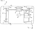
- a vehicle 100 including a regenerative coordination brake control device is described below as a first embodiment of the present invention.
- the vehicle 100 includes an engine 300, serving as a driving source, four tires 50, disposed in a lower portion of the vehicle 100 to support the vehicle 100, and axles 60, having their ends attached to the tires 50 to transmit motive power from the engine 300 to the tires 50.
- engine 300 serving as a driving source
- tires 50 disposed in a lower portion of the vehicle 100 to support the vehicle 100
- axles 60 having their ends attached to the tires 50 to transmit motive power from the engine 300 to the tires 50.
- the vehicle 100 includes hydraulic brakes 10, which serve as friction braking force generators that apply friction to the tires 50 or the axles 60 to cause a friction braking force, a motor 20, which converts electric power to motive power to assist the engine 300, and a battery 31, which supplies electric power to the motor 20.
- the vehicle 100 includes a regenerative brake 30, which serves as a regenerative braking force generator that regenerates motive power of rotation of the axles 60 and coverts it into electric power, and a transmission 40, which transmits the driving force generated by the engine 300 to the axles 60.
- a regenerative brake 30, which serves as a regenerative braking force generator that regenerates motive power of rotation of the axles 60 and coverts it into electric power
- a transmission 40 which transmits the driving force generated by the engine 300 to the axles 60.
- the vehicle 100 includes an ECU 90, which serves as a controller that controls the entirety of the vehicle 100, and a regenerative cooperation ECU 91, which serves as a regenerative coordination brake control device that is electrically connected to the ECU 90 to control the hydraulic brakes 10 and the regenerative brake 30 so that they work in cooperation.
- ECU 90 which serves as a controller that controls the entirety of the vehicle 100
- a regenerative cooperation ECU 91 which serves as a regenerative coordination brake control device that is electrically connected to the ECU 90 to control the hydraulic brakes 10 and the regenerative brake 30 so that they work in cooperation.
- the present embodiment describes the vehicle 100 having a structure in which a driving force is transmitted to the left and right rear tires 50 and the vehicle 100 moves in a Y direction.
- the vehicle 100 may be driven in any type including front-wheel drive, rear-wheel drive, and four-wheel drive.
- the vehicle 100 is a hybrid car including the motor 20 and the engine 300 as driving sources.
- the vehicle 100 may have a structure only including the motor 20, such as a so-called electric vehicle, as a driving source.
- the regenerative cooperation ECU 91 is described as a unit separate from the ECU 90, but may be part of the function of the ECU 90.
- the two axles 60 are arranged side by side in the Y direction, which is a front-rear direction of the vehicle 100.
- the axles 60 are drive shafts extending in an X direction, which is a vehicle-width direction of the vehicle 100, and rotate in an A direction with the operation of the engine 300.
- the tires 50 are pneumatic rubber tires.
- the tires 50 are filled with air of a predetermined pressure.
- the battery 31 serves as a storage battery that stores electric power regenerated by the regenerative brake 30 while allowing the electric power to be supplied to the motor 20.
- the battery 31 also serves as an electric power storage that stores electric power supplied from the outside of the vehicle 100.
- the ECU 90 is a controller that performs controlling on the basis of information acquired from each component of the vehicle 100, such as an amount by which a driver operates the brake pedal or an accelerator pedal.
- the regenerative cooperation ECU 91 includes a prohibition condition determiner 92, serving as a regeneration restriction condition determiner that outputs a regeneration restriction signal S1 when determining that restriction conditions for prohibiting or suppressing regenerative braking, as listed in Table 1 described below, are met.
- the regenerative cooperation ECU 91 includes an acceleration operation detector 93, which serves as an acceleration operation detector that outputs a regeneration restriction removal signal S2 when detecting an acceleration operation of the vehicle 100.
- the regenerative cooperation ECU 91 includes a regeneration prohibited state determiner 94, which serves as a regeneration restriction removal determiner that determines whether regenerative braking of the vehicle 100 that is under restriction is to be continuously restricted or released from the restriction using the prohibition condition determiner 92 and the acceleration operation detector 93, that is, on the basis of the regeneration restriction signal S1 and the regeneration restriction removal signal S2.
- a regeneration prohibited state determiner 94 which serves as a regeneration restriction removal determiner that determines whether regenerative braking of the vehicle 100 that is under restriction is to be continuously restricted or released from the restriction using the prohibition condition determiner 92 and the acceleration operation detector 93, that is, on the basis of the regeneration restriction signal S1 and the regeneration restriction removal signal S2.
- the regeneration restriction signal S1 and the regeneration restriction removal signal S2 are both digital signals representing True or False, that is, values of 1 or 0. That the prohibition condition determiner 92 outputs the regeneration restriction signal S1 represents that the regeneration restriction signal S1 is 1, that is, the regeneration restriction signal S1 is True. The same holds true for the regeneration restriction removal signal S2.
- the present embodiment describes a case where the regenerative braking is switched between a prohibited state and an enabled state.
- a so-called restricted state in which regenerative braking is prohibited or suppressed, and a restriction removed state in which the restriction is removed may be switched between each other.
- the acceleration operation detector 93 includes an accelerator position detector 931, which detects an accelerator position ⁇ , which is an amount by which the accelerator is operated by a driver of the vehicle 100, and a vehicle speed detector 932, which detects the vehicle speed V of the vehicle 100 output from the ECU 90.
- the acceleration operation detector 93 includes a torque calculator 933, which calculates a driver's requiring torque T from the accelerator position ⁇ .
- the acceleration operation detector 93 outputs the regeneration restriction removal signal S2 on condition that the accelerator position ⁇ , the vehicle speed V, and the driver's requiring torque T are respectively greater than or equal to predetermined values ⁇ 1 , V 1 , and T 1 .
- the accelerator position ⁇ detected by the accelerator position detector 931, the vehicle speed V detected by the vehicle speed detector 932, and the driver's requiring torque T calculated by the torque calculator 933 reach or exceed the predetermined values as a result of the driver accelerating the vehicle 100.
- the acceleration operation detector 93 outputs the regeneration restriction removal signal S2 when detecting an acceleration operation of the driver on the basis of information output from the ECU 90.
- information used to determine the existence of such an acceleration operation that is, whether the regeneration restriction removal signal S2 is to be output preferably includes at least the accelerator position ⁇ among the accelerator position ⁇ , the vehicle speed V, and the driver's requiring torque T.
- such an acceleration operation or the driver's operation on the accelerator pedal is input to the regenerative cooperation ECU 91 through the ECU 90.
- the acceleration operation may be directly input to the regenerative cooperation ECU 91.
- the regeneration prohibited state determiner 94 determines that regenerative braking is not the state requiring prohibition, on condition that the regeneration restriction signal S1 is not output and the regeneration restriction removal signal S2 is output.
- the regeneration prohibited state in which the regenerative brake 30 is prohibited from performing regenerative braking, preferably, frequent switching of operations of the regenerative brake 30 is to be avoided, and the regeneration prohibited state is to be removed when the regeneration prohibited conditions are not met.
- Fig. 5 as a comparative example, the following describes a structure that switches regenerative braking between the regeneration prohibited state and the regeneration prohibition removed state, on the basis of whether any of the regeneration prohibited conditions is met, that is, only on the basis of whether the regeneration restriction signal S1 is on or off.
- such a structure that determines whether regenerative braking is in the regeneration prohibited state or the regeneration prohibition removed state every time the brake pedal is operated may frequently switch regenerative braking between the regeneration prohibited state and the regeneration prohibition removed state when, for example, a driver intermittently depresses the brake pedal.
- the regeneration prohibited state determiner 94 switches regenerative braking between the regeneration prohibited state and the regeneration prohibition removed state in consideration of a driver's acceleration intention.
- the acceleration operation detector 93 outputs the regeneration restriction removal signal S2 when detecting an acceleration operation of the driver.
- the regeneration restriction removal signal S2 can be said as being a parameter representing the driver's acceleration intention to accelerate the vehicle.
- the regeneration prohibited state determiner 94 determines that regenerative braking is not in the state requiring prohibition, on condition that the regeneration restriction signal S1 is not output and the regeneration restriction removal signal S2 is output. Based on this determination, the regenerative cooperation ECU 91 cancels the regeneration prohibited state.
- a regenerative cooperation control of the vehicle 100 having the above structure in the normal running state is described with reference to Fig. 3 .
- the ECU 90 When the ECU 90 detects that the driver has operated the brake pedal of the vehicle 100 to decelerate the vehicle 100, the ECU 90 calculates the amount of deceleration required by the driver on the basis of the amount by which the brake pedal is depressed, and outputs the calculated amount to the regenerative cooperation ECU 91.
- the regenerative cooperation ECU 91 calculates a driver's requiring hydraulic pressure W1, which is an intended braking force converted into the hydraulic pressure of the hydraulic brakes 10, on the basis of the amount of deceleration received from the ECU 90.
- the regenerative cooperation ECU 91 calculates, from the operation state of the vehicle 100, such as the number of revolutions of the motor 20 or the charged state of the battery 31, the regenerative braking force caused when the regenerative brake 30 is operated, and outputs the regenerative cooperation required torque, which is a feasible predicted value, to the ECU 90 and the regenerative brake 30.
- the regenerative brake 30 outputs a regenerative braking force actually caused through the operation of the regenerative brake 30, that is, a regeneration performance torque, which is an actual regenerative cooperation torque, to the regenerative cooperation ECU 91.
- the regenerative cooperation ECU 91 converts the regeneration performance torque into a regeneration performance torque hydraulic pressure W2.
- the regeneration performance torque hydraulic pressure W2 is obtained by converting the regenerative braking force equivalent to the regeneration performance torque into a hydraulic pressure required to perform braking using the hydraulic brakes 10.
- the regenerative cooperation ECU 91 outputs a difference between the regeneration performance torque hydraulic pressure W2 and the driver's requiring hydraulic pressure W1 to the hydraulic brakes 10 as a S/C target hydraulic pressure W3, which is a friction braking force.
- the regenerative cooperation ECU 91 controls the regenerative brake 30 and the hydraulic brakes 10 so that the sum of the regenerative braking force generated by the regenerative brake 30 and the friction braking force generated by the hydraulic brakes 10 equals the target braking force.
- the regenerative cooperation ECU 91 that controls the regenerative braking force renders the regenerative braking force as zero under the conditions listed in Table 1. Specifically, when any of regenerative prohibited conditions listed in Table 1 as regenerative cooperation prohibited conditions is met, the regenerative cooperation ECU 91 stops the operation of the regenerative brake 30.
- the frequent switching of the operation of the regenerative brake 30 is to be avoided since the regenerative braking force responds more quickly than the friction braking force.
- the operation of the hydraulic brakes 10 may fail to catch up with frequent switching of the regenerative brake 30, which may degrade the driving performance due to a loss of braking or excessive braking.
- the regeneration prohibited state is to be continuously imposed when any of the regeneration prohibited conditions is met, that is, while the regeneration restriction signal S1 is output.
- the driver's acceleration intention is used to determine whether regenerative braking is to be switched between the regeneration prohibited state, in which regenerative braking is to be prohibited, and the regeneration prohibition removed state, in which regenerative braking is not prohibited.
- regenerative braking is less frequently switched between the regeneration prohibited state and the regeneration prohibition removed state to prevent degradation of the driving performance.
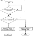
- Fig. 4 illustrates a flowchart representing switching between the regeneration prohibited state according to the present embodiment, in which regenerative braking is to be prohibited, and the regeneration prohibition removed state, in which regenerative braking is not be prohibited.
- This flowchart shows the flow from the regeneration prohibited state as the beginning, then switched to the regeneration prohibition removed state, and then to the normal running.
- step S101 is a prohibited condition determination step to switch regenerative braking to the regeneration prohibited state or to keep regenerative braking in the regeneration prohibited state, on condition that the regeneration restriction signal S1 is output.
- the regeneration prohibited state is kept until all the regeneration prohibited conditions are removed.
- Step S102 is a regeneration enabled condition determination step, which is an acceleration intention determination step for determining the existence of a driver's acceleration intention by detecting an acceleration operation with, for example, a driver's accelerator operation, that is, on condition that the acceleration operation detector 93 has output the regeneration restriction removal signal S2.
- step S103 is a regeneration prohibited state determination step for determining whether regenerative braking is in the state requiring prohibition.
- step S104 When it is determined in step S103 that regenerative braking is not in the state requiring prohibition, the regenerative cooperation ECU 91 switches regenerative braking from the regeneration prohibited state to the regeneration prohibition removed state (step S104).
- the vehicle 100 is controlled in accordance with the operation of the regenerative cooperation ECU 91 in the normal running state.
- the regenerative cooperation ECU 91 includes the prohibition condition determiner 92, which determines that any of the regeneration prohibited conditions is met and outputs the regeneration restriction signal S1, and the acceleration operation detector 93, which detects an acceleration operation of the vehicle 100 and outputs the regeneration restriction removal signal S2.
- the regenerative cooperation ECU 91 includes the regeneration prohibited state determiner 94, which determines whether regenerative braking is in the state requiring prohibition, using the prohibition condition determiner 92 and the acceleration operation detector 93.
- the regeneration prohibited state determiner 94 determines that regenerative braking is not in the state requiring prohibition, on condition that the regeneration restriction signal S1 is not output and the regeneration restriction removal signal S2 is output.
- This structure reduces the frequency of switching regenerative braking between the state requiring prohibition and the state not requiring prohibition.
- the regeneration prohibited state determiner 94 cancels prohibition of regenerative braking in the regeneration prohibited state when the regeneration restriction signal S1 is not output and the regeneration restriction removal signal S2 is output.
- a driver's acceleration intention is used to determine whether regenerative braking is to be switched between the regeneration prohibited state requiring prohibition and the regeneration prohibition removed state not requiring prohibition.
- regenerative braking is less frequently switched between the regeneration prohibited state and the regeneration prohibition removed state to suppress degradation of the driving performance.
- the acceleration operation detector 93 includes the accelerator position detector 931, which detects the accelerator position ⁇ operated by the driver of the vehicle 100.
- the acceleration operation detector 93 outputs the regeneration restriction removal signal S2 on condition that the accelerator position ⁇ is greater than or equal to the predetermined value ⁇ 1 .
- a driver's acceleration intention is used to determine whether regenerative braking is to be switched between the regeneration prohibited state requiring prohibition and the regeneration prohibition removed state not requiring prohibition.
- regenerative braking is less frequently switched between the regeneration prohibited state and the regeneration prohibition removed state to suppress degradation of the driving performance.
- the acceleration operation detector 93 includes the vehicle speed detector 932, which detects the vehicle speed V of the vehicle 100.
- the acceleration operation detector 93 outputs the regeneration restriction removal signal S2 on condition that the vehicle speed V is greater than or equal to the predetermined value V 1 .
- a driver's acceleration intention is used to determine whether regenerative braking is to be switched between the regeneration prohibited state requiring prohibition and the regeneration prohibition removed state not requiring prohibition.
- regenerative braking is less frequently switched between the regeneration prohibited state and the regeneration prohibition removed state to suppress degradation of the driving performance.
- the acceleration operation detector 93 includes the torque calculator 933, which calculates the driver's requiring torque T from the accelerator position ⁇ .
- the acceleration operation detector 93 outputs the regeneration restriction removal signal S2 on condition that the driver's requiring torque T is greater than or equal to the predetermined value T 1 .
- a driver's acceleration intention is used to determine whether regenerative braking is to be switched between the regeneration prohibited state requiring prohibition and the regeneration prohibition removed state not requiring prohibition.
- regenerative braking is less frequently switched between the regeneration prohibited state and the regeneration prohibition removed state to suppress degradation of the driving performance.
- the acceleration operation detector detects an acceleration operation using the accelerator position, the vehicle speed, and the driver's requiring torque.
- the structure is not limited to the above structure, and may be any structure that detects an acceleration operation using other indexes reflecting a driver's acceleration intention.
- the vehicle includes an internal combustion engine besides a motor.
- the vehicle may be an electric vehicle including only a motor as a motive power source.
- the vehicle includes another electric power source such as a battery.
Landscapes
- Engineering & Computer Science (AREA)
- Transportation (AREA)
- Mechanical Engineering (AREA)
- Power Engineering (AREA)
- Physics & Mathematics (AREA)
- Electromagnetism (AREA)
- Electric Propulsion And Braking For Vehicles (AREA)
- Regulating Braking Force (AREA)
Claims (5)
- Steuervorrichtung für eine regenerative Bremse, wobei die Steuervorrichtung dazu eingerichtet ist, einen Regenerativbremskraftgenerator (30) eines Fahrzeugs (100) zu steuern, aufweisend:eine Regenerationsbeschränkungsbedingungs-Feststelleinrichtung (92), die dazu eingerichtet ist, ein Regenerationsbeschränkungssignal (S1) auszugeben, wenn festgestellt wird, dass eine Regenerationsbeschränkungsbedingung zum Verbieten oder Unterdrücken des regenerativen Bremsens erfüllt ist;einen Beschleunigungsbetriebsdetektor (93), der dazu eingerichtet ist, ein Regenerationsbeschränkungs-Aufhebungssignal (S2) auszugeben, wenn ein Beschleunigungsbetrieb des Fahrzeugs (100) detektiert wird; undeine Regenerationsbeschränkungs-Aufhebungsfeststelleinrichtung (94), die dazu eingerichtet ist, unter Verwendung des Regenerationsbeschränkungssignals (S1) und des Regenerationsbeschränkungs-Aufhebungssignals (S2) festzustellen, ob eine Beschränkung des regenerativen Bremsens des Fahrzeugs (100), das sich in einem beschränkten Zustand befindet, kontinuierlich auferlegt oder aufgehoben werden soll, dadurch gekennzeichnet, dass, wenn der Beschleunigungsbetriebsdetektor (93) das Regenerationsbeschränkungs-Aufhebungssignal (S2) nicht ausgibt, die Regenerationsbeschränkungs-Aufhebungsfeststelleinrichtung (94) dazu eingerichtet ist, festzustellen, dass die Beschränkung des regenerativen Bremsens des Fahrzeugs (100) kontinuierlich auferlegt werden soll; wenn der Beschleunigungsbetriebsdetektor (93) das Regenerationsbeschränkungs-Aufhebungssignal (S2) ausgibt: wenn die Regenerationsbeschränkungsbedingungs-Feststelleinrichtung (92) das Regenerationsbeschränkungssignal (S1) ausgibt, die Regenerationsbeschränkungs-Aufhebungsfeststelleinrichtung (94) dazu eingerichtet ist, festzustellen, dass die Beschränkung des regenerativen Bremsens des Fahrzeugs (100) kontinuierlich auferlegt werden soll; wenn die Regenerationsbeschränkungsbedingungs-Feststelleinrichtung (92) das Regenerationsbeschränkungssignal (S1) nicht ausgibt, die Regenerationsbeschränkungs-Aufhebungsfeststelleinrichtung (94) dazu eingerichtet ist, festzustellen, dass die Beschränkung des regenerativen Bremsens des Fahrzeugs (100) aufgehoben werden soll;die Steuervorrichtung für eine regenerative Bremse dazu eingerichtet ist, den Regenerativbremskraftgenerator (30) des Fahrzeugs (100) basierend auf der Feststellung der Regenerationsbeschränkungs-Aufhebungsfeststelleinrichtung (94) zu steuern.
- Steuervorrichtung für eine regenerative Bremse nach Anspruch 1, wobei das regenerative Bremsen von der Beschränkung entlastet wird, wenn die Regenerationsbeschränkungs-Aufhebungsfeststelleinrichtung (94) feststellt, dass die Beschränkung des regenerativen Bremsens aufgehoben werden soll.
- Steuervorrichtung für eine regenerative Bremse nach Anspruch 1 oder 2, wobei der Beschleunigungsbetriebsdetektor (93) einen Fahrpedalpositionsdetektor (931) aufweist, der dazu eingerichtet ist, einen Betrag einer Fahrpedalbedienung zu detektieren, die durch einen Fahrer des Fahrzeugs (100) durchgeführt wird, und der Beschleunigungsbetriebsdetektor (93) dazu eingerichtet ist, das Regenerationsbeschränkungs-Aufhebungssignal (S2) unter der Bedingung, dass der Betrag der Fahrpedalbedienung größer als oder gleich einem vorbestimmtem Wert ist, auszugeben.
- Steuervorrichtung für eine regenerative Bremse nach Anspruch 3, die ferner aufweist:einen Fahrzeuggeschwindigkeitsdetektor (932), der dazu eingerichtet ist, eine Geschwindigkeit des Fahrzeugs (100) zu detektieren,wobei die Beschränkung des regenerativen Bremsens aufgehoben wird, wenn die Regenerationsbeschränkungs-Aufhebungsfeststelleinrichtung (94) feststellt, dass die Beschränkung des regenerativen Bremsens aufgehoben werden soll, und die Fahrzeuggeschwindigkeit größer als oder gleich einem vorbestimmtem Wert ist.
- Steuervorrichtung für eine regenerative Bremse nach Anspruch 3 oder 4, wobei der Beschleunigungsbetriebsdetektor (93) eine Drehmomentberechnungseinrichtung (933) aufweist, die dazu eingerichtet ist, ein vom Fahrer angefordertes Drehmoment aus dem Betrag der Fahrpedalbedienung zu berechnen, und der Beschleunigungsbetriebsdetektor (93) dazu eingerichtet ist, das Regenerationsbeschränkungs-Aufhebungssignal (S2) unter der Bedingung, dass das vom Fahrer angeforderte Drehmoment größer als oder gleich einem vorbestimmtem Wert ist, auszugeben.
Applications Claiming Priority (2)
| Application Number | Priority Date | Filing Date | Title |
|---|---|---|---|
| JP2015183172 | 2015-09-16 | ||
| PCT/JP2016/004153 WO2017047071A1 (ja) | 2015-09-16 | 2016-09-13 | 回生ブレーキ制御装置 |
Publications (3)
| Publication Number | Publication Date |
|---|---|
| EP3351442A1 EP3351442A1 (de) | 2018-07-25 |
| EP3351442A4 EP3351442A4 (de) | 2019-05-08 |
| EP3351442B1 true EP3351442B1 (de) | 2022-02-09 |
Family
ID=58288499
Family Applications (1)
| Application Number | Title | Priority Date | Filing Date |
|---|---|---|---|
| EP16845945.1A Active EP3351442B1 (de) | 2015-09-16 | 2016-09-13 | Steuerungsvorrichtung für eine regenerative bremse |
Country Status (5)
| Country | Link |
|---|---|
| US (1) | US10449863B2 (de) |
| EP (1) | EP3351442B1 (de) |
| JP (1) | JP6508346B2 (de) |
| CN (1) | CN108025710B (de) |
| WO (1) | WO2017047071A1 (de) |
Cited By (1)
| Publication number | Priority date | Publication date | Assignee | Title |
|---|---|---|---|---|
| EP4674706A1 (de) * | 2024-07-05 | 2026-01-07 | FERRARI S.p.A. | Steuerungsverfahren für regenerative bremsung mit antiblockierbremssystem eines strassenfahrzeugs mit unabhängigen elektromotoren und zugehöriges strassenfahrzeug |
Families Citing this family (5)
| Publication number | Priority date | Publication date | Assignee | Title |
|---|---|---|---|---|
| KR102406065B1 (ko) * | 2016-12-14 | 2022-06-08 | 현대자동차주식회사 | 마일드 하이브리드 차량의 에너지 회생 제어 방법 |
| US12377831B2 (en) | 2019-04-18 | 2025-08-05 | Continental Automotive Technologies GmbH | Method for operating a vehicle brake system, and brake system |
| JP7383929B2 (ja) * | 2019-08-13 | 2023-11-21 | 株式会社豊田自動織機 | 産業用車両 |
| KR20210072863A (ko) * | 2019-12-09 | 2021-06-18 | 현대자동차주식회사 | 하이브리드 상용차용 회생제동 제어 장치 및 방법 |
| US20240317230A1 (en) * | 2023-03-21 | 2024-09-26 | Scott C Harris | Smart Regenerative Braking for Electric Vehicles |
Family Cites Families (20)
| Publication number | Priority date | Publication date | Assignee | Title |
|---|---|---|---|---|
| JPH0879907A (ja) * | 1994-09-01 | 1996-03-22 | Mitsubishi Motors Corp | 電気自動車用回生ブレーキ制御装置 |
| JP3685920B2 (ja) * | 1997-09-14 | 2005-08-24 | 本田技研工業株式会社 | ハイブリッド車用電動機制御装置 |
| JP3541646B2 (ja) | 1997-10-13 | 2004-07-14 | トヨタ自動車株式会社 | 制動力制御装置 |
| CN2356887Y (zh) * | 1998-04-17 | 2000-01-05 | 傅电明 | 一种电动车联动制动装置 |
| JP2007001403A (ja) * | 2005-06-23 | 2007-01-11 | Toyota Motor Corp | ハイブリッド自動車及びその制御方法 |
| JP4321668B2 (ja) * | 2006-02-28 | 2009-08-26 | トヨタ自動車株式会社 | 車両駆動装置 |
| JP5458788B2 (ja) * | 2009-10-13 | 2014-04-02 | アイシン精機株式会社 | 動力伝達装置および動力伝達装置の制御装置 |
| JPWO2013084682A1 (ja) * | 2011-12-09 | 2015-04-27 | 本田技研工業株式会社 | 電動車両の制御装置及び制御方法 |
| JP5915208B2 (ja) | 2012-01-31 | 2016-05-11 | 日産自動車株式会社 | 電動車両の回生ブレーキ制御装置 |
| CN104159775B (zh) | 2012-03-07 | 2016-10-05 | 日产自动车株式会社 | 制动控制装置 |
| JP5790870B2 (ja) * | 2012-03-14 | 2015-10-07 | 日産自動車株式会社 | 制動制御装置及び制御方法 |
| JP5596756B2 (ja) * | 2012-08-29 | 2014-09-24 | トヨタ自動車株式会社 | 電動車両 |
| DE102013217579B4 (de) * | 2013-09-04 | 2025-09-11 | Robert Bosch Gmbh | Verfahren zum Betreiben eines elektromechanischen Bremskraftverstärkers eines Bremssystems, Verfahren zum Betreiben eines rekuperativen Bremssystems und Steuervorrichtung für zumindest einen elektromechanischen Bremskraftverstärker eines Bremssystems |
| US9352744B2 (en) * | 2014-01-17 | 2016-05-31 | Ford Global Technologies, Llc | Hybrid vehicle braking limit determination system and method |
| JP6219186B2 (ja) * | 2014-01-31 | 2017-10-25 | 日立オートモティブシステムズ株式会社 | ブレーキ制御装置 |
| JP6439322B2 (ja) * | 2014-08-27 | 2018-12-19 | 三菱自動車工業株式会社 | ハイブリッド車両の回生制御装置 |
| JP6649600B2 (ja) * | 2015-08-03 | 2020-02-19 | 三菱自動車工業株式会社 | 電動車両の回生制御装置 |
| JP6641846B2 (ja) * | 2015-09-30 | 2020-02-05 | 三菱自動車工業株式会社 | 回生ブレーキ制御装置 |
| US9994108B2 (en) * | 2016-08-29 | 2018-06-12 | Ford Global Technologies, Llc | Regenerative braking power distribution |
| KR102540917B1 (ko) * | 2016-12-15 | 2023-06-07 | 현대자동차주식회사 | 전기 차량용 모터 토크 제어 방법 |
-
2016
- 2016-09-13 JP JP2017540502A patent/JP6508346B2/ja active Active
- 2016-09-13 CN CN201680053651.4A patent/CN108025710B/zh active Active
- 2016-09-13 US US15/760,448 patent/US10449863B2/en active Active
- 2016-09-13 WO PCT/JP2016/004153 patent/WO2017047071A1/ja not_active Ceased
- 2016-09-13 EP EP16845945.1A patent/EP3351442B1/de active Active
Cited By (1)
| Publication number | Priority date | Publication date | Assignee | Title |
|---|---|---|---|---|
| EP4674706A1 (de) * | 2024-07-05 | 2026-01-07 | FERRARI S.p.A. | Steuerungsverfahren für regenerative bremsung mit antiblockierbremssystem eines strassenfahrzeugs mit unabhängigen elektromotoren und zugehöriges strassenfahrzeug |
Also Published As
| Publication number | Publication date |
|---|---|
| CN108025710B (zh) | 2020-08-04 |
| JPWO2017047071A1 (ja) | 2018-07-12 |
| EP3351442A4 (de) | 2019-05-08 |
| WO2017047071A1 (ja) | 2017-03-23 |
| US20180257491A1 (en) | 2018-09-13 |
| US10449863B2 (en) | 2019-10-22 |
| JP6508346B2 (ja) | 2019-05-08 |
| EP3351442A1 (de) | 2018-07-25 |
| CN108025710A (zh) | 2018-05-11 |
Similar Documents
| Publication | Publication Date | Title |
|---|---|---|
| EP3351442B1 (de) | Steuerungsvorrichtung für eine regenerative bremse | |
| US8886375B2 (en) | Control apparatus for electric vehicle | |
| CN111601731B (zh) | 电动车辆的控制装置、控制系统以及控制方法 | |
| US8634987B2 (en) | Control apparatus for electric vehicle | |
| US8892281B2 (en) | Torque control system for suppressing vibration in an electric vehicle | |
| KR100520565B1 (ko) | 사륜 구동 전기자동차의 회생 제동 제어방법 및 시스템 | |
| US9849786B2 (en) | Vehicle system and method for adjusting deceleration rate | |
| JP6898843B2 (ja) | 電動車両の制御装置、制御方法および制御システム | |
| US20100049414A1 (en) | Control apparatus for electric vehicle | |
| US9440540B2 (en) | Electric vehicle and control method | |
| KR20140053701A (ko) | E-4wd 하이브리드 전기자동차의 제어장치 및 방법 | |
| WO2011048660A1 (ja) | スタンバイ四輪駆動車両の駆動制御装置 | |
| US9545849B2 (en) | Vehicle system and method for adapting lift pedal regeneration | |
| US10889188B2 (en) | Drive control device for vehicle with independently driven wheels | |
| KR20160040629A (ko) | 차량 | |
| JP6788546B2 (ja) | 車両用制動システム | |
| JP2015110378A (ja) | 車両用制動装置 | |
| US9950697B2 (en) | Braking-driving force control system and braking-driving force control method | |
| US20240123834A1 (en) | Control device for vehicle | |
| JP2019187019A (ja) | 電動車両の制御装置 | |
| KR20170119534A (ko) | 마일드 하이브리드 차량용 크루즈 제어 방법 및 장치 | |
| KR20160040913A (ko) | 스마트 전기자동차 및 그 동작 방법 | |
| KR100579925B1 (ko) | 4륜 하이브리드 전기자동차의 슬립 제어장치 및 방법 | |
| JP2013158200A (ja) | パッシブトルクスプリット4輪駆動車 | |
| JP2018001775A (ja) | 車両のブレーキ装置 |
Legal Events
| Date | Code | Title | Description |
|---|---|---|---|
| STAA | Information on the status of an ep patent application or granted ep patent |
Free format text: STATUS: THE INTERNATIONAL PUBLICATION HAS BEEN MADE |
|
| PUAI | Public reference made under article 153(3) epc to a published international application that has entered the european phase |
Free format text: ORIGINAL CODE: 0009012 |
|
| STAA | Information on the status of an ep patent application or granted ep patent |
Free format text: STATUS: REQUEST FOR EXAMINATION WAS MADE |
|
| 17P | Request for examination filed |
Effective date: 20180329 |
|
| AK | Designated contracting states |
Kind code of ref document: A1 Designated state(s): AL AT BE BG CH CY CZ DE DK EE ES FI FR GB GR HR HU IE IS IT LI LT LU LV MC MK MT NL NO PL PT RO RS SE SI SK SM TR |
|
| AX | Request for extension of the european patent |
Extension state: BA ME |
|
| DAV | Request for validation of the european patent (deleted) | ||
| DAX | Request for extension of the european patent (deleted) | ||
| A4 | Supplementary search report drawn up and despatched |
Effective date: 20190404 |
|
| RIC1 | Information provided on ipc code assigned before grant |
Ipc: B60T 8/171 20060101ALI20190329BHEP Ipc: B60L 15/20 20060101ALI20190329BHEP Ipc: B60L 7/18 20060101ALI20190329BHEP Ipc: B60T 8/172 20060101ALI20190329BHEP Ipc: B60T 8/17 20060101AFI20190329BHEP Ipc: B60L 7/24 20060101ALI20190329BHEP |
|
| RAP1 | Party data changed (applicant data changed or rights of an application transferred) |
Owner name: MITSUBISHI JIDOSHA KOGYO KABUSHIKI KAISHA |
|
| STAA | Information on the status of an ep patent application or granted ep patent |
Free format text: STATUS: EXAMINATION IS IN PROGRESS |
|
| 17Q | First examination report despatched |
Effective date: 20201116 |
|
| GRAP | Despatch of communication of intention to grant a patent |
Free format text: ORIGINAL CODE: EPIDOSNIGR1 |
|
| STAA | Information on the status of an ep patent application or granted ep patent |
Free format text: STATUS: GRANT OF PATENT IS INTENDED |
|
| INTG | Intention to grant announced |
Effective date: 20210903 |
|
| GRAS | Grant fee paid |
Free format text: ORIGINAL CODE: EPIDOSNIGR3 |
|
| GRAA | (expected) grant |
Free format text: ORIGINAL CODE: 0009210 |
|
| STAA | Information on the status of an ep patent application or granted ep patent |
Free format text: STATUS: THE PATENT HAS BEEN GRANTED |
|
| AK | Designated contracting states |
Kind code of ref document: B1 Designated state(s): AL AT BE BG CH CY CZ DE DK EE ES FI FR GB GR HR HU IE IS IT LI LT LU LV MC MK MT NL NO PL PT RO RS SE SI SK SM TR |
|
| REG | Reference to a national code |
Ref country code: GB Ref legal event code: FG4D |
|
| REG | Reference to a national code |
Ref country code: CH Ref legal event code: EP Ref country code: AT Ref legal event code: REF Ref document number: 1467310 Country of ref document: AT Kind code of ref document: T Effective date: 20220215 |
|
| REG | Reference to a national code |
Ref country code: IE Ref legal event code: FG4D |
|
| REG | Reference to a national code |
Ref country code: DE Ref legal event code: R096 Ref document number: 602016069034 Country of ref document: DE |
|
| REG | Reference to a national code |
Ref country code: LT Ref legal event code: MG9D |
|
| REG | Reference to a national code |
Ref country code: NL Ref legal event code: MP Effective date: 20220209 |
|
| REG | Reference to a national code |
Ref country code: AT Ref legal event code: MK05 Ref document number: 1467310 Country of ref document: AT Kind code of ref document: T Effective date: 20220209 |
|
| PG25 | Lapsed in a contracting state [announced via postgrant information from national office to epo] |
Ref country code: SE Free format text: LAPSE BECAUSE OF FAILURE TO SUBMIT A TRANSLATION OF THE DESCRIPTION OR TO PAY THE FEE WITHIN THE PRESCRIBED TIME-LIMIT Effective date: 20220209 Ref country code: RS Free format text: LAPSE BECAUSE OF FAILURE TO SUBMIT A TRANSLATION OF THE DESCRIPTION OR TO PAY THE FEE WITHIN THE PRESCRIBED TIME-LIMIT Effective date: 20220209 Ref country code: PT Free format text: LAPSE BECAUSE OF FAILURE TO SUBMIT A TRANSLATION OF THE DESCRIPTION OR TO PAY THE FEE WITHIN THE PRESCRIBED TIME-LIMIT Effective date: 20220609 Ref country code: NO Free format text: LAPSE BECAUSE OF FAILURE TO SUBMIT A TRANSLATION OF THE DESCRIPTION OR TO PAY THE FEE WITHIN THE PRESCRIBED TIME-LIMIT Effective date: 20220509 Ref country code: NL Free format text: LAPSE BECAUSE OF FAILURE TO SUBMIT A TRANSLATION OF THE DESCRIPTION OR TO PAY THE FEE WITHIN THE PRESCRIBED TIME-LIMIT Effective date: 20220209 Ref country code: LT Free format text: LAPSE BECAUSE OF FAILURE TO SUBMIT A TRANSLATION OF THE DESCRIPTION OR TO PAY THE FEE WITHIN THE PRESCRIBED TIME-LIMIT Effective date: 20220209 Ref country code: HR Free format text: LAPSE BECAUSE OF FAILURE TO SUBMIT A TRANSLATION OF THE DESCRIPTION OR TO PAY THE FEE WITHIN THE PRESCRIBED TIME-LIMIT Effective date: 20220209 Ref country code: ES Free format text: LAPSE BECAUSE OF FAILURE TO SUBMIT A TRANSLATION OF THE DESCRIPTION OR TO PAY THE FEE WITHIN THE PRESCRIBED TIME-LIMIT Effective date: 20220209 Ref country code: BG Free format text: LAPSE BECAUSE OF FAILURE TO SUBMIT A TRANSLATION OF THE DESCRIPTION OR TO PAY THE FEE WITHIN THE PRESCRIBED TIME-LIMIT Effective date: 20220509 |
|
| PG25 | Lapsed in a contracting state [announced via postgrant information from national office to epo] |
Ref country code: PL Free format text: LAPSE BECAUSE OF FAILURE TO SUBMIT A TRANSLATION OF THE DESCRIPTION OR TO PAY THE FEE WITHIN THE PRESCRIBED TIME-LIMIT Effective date: 20220209 Ref country code: LV Free format text: LAPSE BECAUSE OF FAILURE TO SUBMIT A TRANSLATION OF THE DESCRIPTION OR TO PAY THE FEE WITHIN THE PRESCRIBED TIME-LIMIT Effective date: 20220209 Ref country code: GR Free format text: LAPSE BECAUSE OF FAILURE TO SUBMIT A TRANSLATION OF THE DESCRIPTION OR TO PAY THE FEE WITHIN THE PRESCRIBED TIME-LIMIT Effective date: 20220510 Ref country code: FI Free format text: LAPSE BECAUSE OF FAILURE TO SUBMIT A TRANSLATION OF THE DESCRIPTION OR TO PAY THE FEE WITHIN THE PRESCRIBED TIME-LIMIT Effective date: 20220209 Ref country code: AT Free format text: LAPSE BECAUSE OF FAILURE TO SUBMIT A TRANSLATION OF THE DESCRIPTION OR TO PAY THE FEE WITHIN THE PRESCRIBED TIME-LIMIT Effective date: 20220209 |
|
| PG25 | Lapsed in a contracting state [announced via postgrant information from national office to epo] |
Ref country code: IS Free format text: LAPSE BECAUSE OF FAILURE TO SUBMIT A TRANSLATION OF THE DESCRIPTION OR TO PAY THE FEE WITHIN THE PRESCRIBED TIME-LIMIT Effective date: 20220609 |
|
| PG25 | Lapsed in a contracting state [announced via postgrant information from national office to epo] |
Ref country code: SM Free format text: LAPSE BECAUSE OF FAILURE TO SUBMIT A TRANSLATION OF THE DESCRIPTION OR TO PAY THE FEE WITHIN THE PRESCRIBED TIME-LIMIT Effective date: 20220209 Ref country code: SK Free format text: LAPSE BECAUSE OF FAILURE TO SUBMIT A TRANSLATION OF THE DESCRIPTION OR TO PAY THE FEE WITHIN THE PRESCRIBED TIME-LIMIT Effective date: 20220209 Ref country code: RO Free format text: LAPSE BECAUSE OF FAILURE TO SUBMIT A TRANSLATION OF THE DESCRIPTION OR TO PAY THE FEE WITHIN THE PRESCRIBED TIME-LIMIT Effective date: 20220209 Ref country code: EE Free format text: LAPSE BECAUSE OF FAILURE TO SUBMIT A TRANSLATION OF THE DESCRIPTION OR TO PAY THE FEE WITHIN THE PRESCRIBED TIME-LIMIT Effective date: 20220209 Ref country code: DK Free format text: LAPSE BECAUSE OF FAILURE TO SUBMIT A TRANSLATION OF THE DESCRIPTION OR TO PAY THE FEE WITHIN THE PRESCRIBED TIME-LIMIT Effective date: 20220209 Ref country code: CZ Free format text: LAPSE BECAUSE OF FAILURE TO SUBMIT A TRANSLATION OF THE DESCRIPTION OR TO PAY THE FEE WITHIN THE PRESCRIBED TIME-LIMIT Effective date: 20220209 |
|
| REG | Reference to a national code |
Ref country code: DE Ref legal event code: R097 Ref document number: 602016069034 Country of ref document: DE |
|
| PG25 | Lapsed in a contracting state [announced via postgrant information from national office to epo] |
Ref country code: AL Free format text: LAPSE BECAUSE OF FAILURE TO SUBMIT A TRANSLATION OF THE DESCRIPTION OR TO PAY THE FEE WITHIN THE PRESCRIBED TIME-LIMIT Effective date: 20220209 |
|
| PLBE | No opposition filed within time limit |
Free format text: ORIGINAL CODE: 0009261 |
|
| STAA | Information on the status of an ep patent application or granted ep patent |
Free format text: STATUS: NO OPPOSITION FILED WITHIN TIME LIMIT |
|
| 26N | No opposition filed |
Effective date: 20221110 |
|
| PG25 | Lapsed in a contracting state [announced via postgrant information from national office to epo] |
Ref country code: SI Free format text: LAPSE BECAUSE OF FAILURE TO SUBMIT A TRANSLATION OF THE DESCRIPTION OR TO PAY THE FEE WITHIN THE PRESCRIBED TIME-LIMIT Effective date: 20220209 |
|
| PG25 | Lapsed in a contracting state [announced via postgrant information from national office to epo] |
Ref country code: MC Free format text: LAPSE BECAUSE OF FAILURE TO SUBMIT A TRANSLATION OF THE DESCRIPTION OR TO PAY THE FEE WITHIN THE PRESCRIBED TIME-LIMIT Effective date: 20220209 |
|
| REG | Reference to a national code |
Ref country code: CH Ref legal event code: PL |
|
| GBPC | Gb: european patent ceased through non-payment of renewal fee |
Effective date: 20220913 |
|
| REG | Reference to a national code |
Ref country code: BE Ref legal event code: MM Effective date: 20220930 |
|
| PG25 | Lapsed in a contracting state [announced via postgrant information from national office to epo] |
Ref country code: LU Free format text: LAPSE BECAUSE OF NON-PAYMENT OF DUE FEES Effective date: 20220913 |
|
| PG25 | Lapsed in a contracting state [announced via postgrant information from national office to epo] |
Ref country code: LI Free format text: LAPSE BECAUSE OF NON-PAYMENT OF DUE FEES Effective date: 20220930 Ref country code: IT Free format text: LAPSE BECAUSE OF FAILURE TO SUBMIT A TRANSLATION OF THE DESCRIPTION OR TO PAY THE FEE WITHIN THE PRESCRIBED TIME-LIMIT Effective date: 20220209 Ref country code: IE Free format text: LAPSE BECAUSE OF NON-PAYMENT OF DUE FEES Effective date: 20220913 Ref country code: CH Free format text: LAPSE BECAUSE OF NON-PAYMENT OF DUE FEES Effective date: 20220930 |
|
| PG25 | Lapsed in a contracting state [announced via postgrant information from national office to epo] |
Ref country code: BE Free format text: LAPSE BECAUSE OF NON-PAYMENT OF DUE FEES Effective date: 20220930 |
|
| PG25 | Lapsed in a contracting state [announced via postgrant information from national office to epo] |
Ref country code: GB Free format text: LAPSE BECAUSE OF NON-PAYMENT OF DUE FEES Effective date: 20220913 |
|
| PG25 | Lapsed in a contracting state [announced via postgrant information from national office to epo] |
Ref country code: HU Free format text: LAPSE BECAUSE OF FAILURE TO SUBMIT A TRANSLATION OF THE DESCRIPTION OR TO PAY THE FEE WITHIN THE PRESCRIBED TIME-LIMIT; INVALID AB INITIO Effective date: 20160913 |
|
| PG25 | Lapsed in a contracting state [announced via postgrant information from national office to epo] |
Ref country code: CY Free format text: LAPSE BECAUSE OF FAILURE TO SUBMIT A TRANSLATION OF THE DESCRIPTION OR TO PAY THE FEE WITHIN THE PRESCRIBED TIME-LIMIT Effective date: 20220209 |
|
| PG25 | Lapsed in a contracting state [announced via postgrant information from national office to epo] |
Ref country code: MK Free format text: LAPSE BECAUSE OF FAILURE TO SUBMIT A TRANSLATION OF THE DESCRIPTION OR TO PAY THE FEE WITHIN THE PRESCRIBED TIME-LIMIT Effective date: 20220209 |
|
| PG25 | Lapsed in a contracting state [announced via postgrant information from national office to epo] |
Ref country code: TR Free format text: LAPSE BECAUSE OF FAILURE TO SUBMIT A TRANSLATION OF THE DESCRIPTION OR TO PAY THE FEE WITHIN THE PRESCRIBED TIME-LIMIT Effective date: 20220209 |
|
| PG25 | Lapsed in a contracting state [announced via postgrant information from national office to epo] |
Ref country code: MT Free format text: LAPSE BECAUSE OF FAILURE TO SUBMIT A TRANSLATION OF THE DESCRIPTION OR TO PAY THE FEE WITHIN THE PRESCRIBED TIME-LIMIT Effective date: 20220209 |
|
| PGFP | Annual fee paid to national office [announced via postgrant information from national office to epo] |
Ref country code: DE Payment date: 20250730 Year of fee payment: 10 |
|
| PGFP | Annual fee paid to national office [announced via postgrant information from national office to epo] |
Ref country code: FR Payment date: 20250808 Year of fee payment: 10 |