EP3353505B1 - Ultraschalldurchflussmesser selbstabstimmung für reziproken betrieb des zählers - Google Patents
Ultraschalldurchflussmesser selbstabstimmung für reziproken betrieb des zählers Download PDFInfo
- Publication number
- EP3353505B1 EP3353505B1 EP16849714.7A EP16849714A EP3353505B1 EP 3353505 B1 EP3353505 B1 EP 3353505B1 EP 16849714 A EP16849714 A EP 16849714A EP 3353505 B1 EP3353505 B1 EP 3353505B1
- Authority
- EP
- European Patent Office
- Prior art keywords
- value
- component
- determining
- signal
- data point
- Prior art date
- Legal status (The legal status is an assumption and is not a legal conclusion. Google has not performed a legal analysis and makes no representation as to the accuracy of the status listed.)
- Active
Links
Images


Classifications
-
- G—PHYSICS
- G01—MEASURING; TESTING
- G01F—MEASURING VOLUME, VOLUME FLOW, MASS FLOW OR LIQUID LEVEL; METERING BY VOLUME
- G01F1/00—Measuring the volume flow or mass flow of fluid or fluent solid material wherein the fluid passes through a meter in a continuous flow
- G01F1/66—Measuring the volume flow or mass flow of fluid or fluent solid material wherein the fluid passes through a meter in a continuous flow by measuring frequency, phase shift or propagation time of electromagnetic or other waves, e.g. using ultrasonic flowmeters
- G01F1/667—Arrangements of transducers for ultrasonic flowmeters; Circuits for operating ultrasonic flowmeters
-
- G—PHYSICS
- G01—MEASURING; TESTING
- G01F—MEASURING VOLUME, VOLUME FLOW, MASS FLOW OR LIQUID LEVEL; METERING BY VOLUME
- G01F25/00—Testing or calibration of apparatus for measuring volume, volume flow or liquid level or for metering by volume
- G01F25/10—Testing or calibration of apparatus for measuring volume, volume flow or liquid level or for metering by volume of flowmeters
Definitions
- This relates generally to ultrasonic flow meters, and more particularly to automatically detecting an imbalance between a pair of transducers and tuning the transducer circuits to restore balance.
- Ultrasound technology is utilized for measuring fluid/gas velocity through a pipe of known dimensions, with ultrasound transducers placed within the pipes to determine the fluid/gas velocity and the fluid/gas volume flow, which is measured by multiplying fluid/gas velocity by the interior area of the pipe. Cumulative fluid volume may be measured by integrating fluid flow over time.
- two transducers are spaced apart within a pipe such that a first signal is sent in the upstream direction and a second signal is sent in the downstream direction.
- the time-of-flight (TOF) for both signals is measured, with the difference between the two measurements indicating the amount of flow within the pipe. Reciprocal operation in the two directions is critical as the measurements must attain a high degree of accuracy, such as to detect small leaks.
- a tuned flow meter can detect a difference in TOF in the range of picoseconds.
- Providing the necessary reciprocal operation means attaining zero differential TOF at zero flow despite mismatches in transducer pairs. Achieving this goal requires perfect matching of electrical impedances between the transmitting circuit and the receiving circuit.
- a common way to attain matching is by designing the ultrasonic hardware to be voltage transmit, i.e., with close to zero impedance on the driver side, and current receive, i.e., with close to zero impedance on the receiver side. Attaining zero impedance places stringent requirements on both the driver and the receiver circuits to behave as ideal circuits.
- the standards further require that flow meters be designed for a life span of 15-20 years. Over time, changes can occur, either within the pipe or to the transducer itself (such as sedimentation, corrosion, aging), causing drifting of the acoustical impedance. When this occurs, the flow meter may need to be either retuned or replaced, both of which require attention from a technician.
- JP 2007 155574 discloses an ultrasonic flowmeter.
- the invention comprises a method of auto-tuning a first circuit associated with an upstream transducer UPT and a second circuit associated with a downstream transducer DNT for reciprocal operation in an ultrasonic flowmeter according to claim 1.
- the invention further comprises an integrated circuit chip for auto-tuning a first circuit operably connected with an upstream transducer UPT and a second circuit operably connected with a downstream transducer DNT for reciprocal operation in an ultrasonic flowmeter according to claim 7.
- a lack of reciprocity in the upstream/downstream signals results in a frequency offset of the received wave.
- Digital signal processing techniques are disclosed to estimate how closely upstream and downstream waveforms match by estimating the difference in resonating frequency and/or amplitude between the upstream signal and the downstream signal. Instead of attempting a point-for-point match in the signals, the difference between the maximum amplitude of the upstream signal and the downstream signal is useful to detect a mismatch and estimate its magnitude. Similarly, the difference between the center frequency of a fast Fourier transform (FFT) of the upstream signal and the downstream signal can additionally be used to detect a mismatch and estimate its magnitude.
- FFT fast Fourier transform
- one of the following two techniques can be utilized: adaptively tune the impedance of the transmitter or the receiver so that the same frequency is received in the two directions; or provide compensation in digital processing of the signals with no tuning of the impedances.
- Tuning of the impedance can be automatically performed by adjusting two components of the impedance - resistance and capacitance - using variable resistors and capacitors in the circuitry. Tuning the impedance can be done on the fly, with no need to stop the flow in order to measure the zero flow offset.
- Advantages of the disclosed device and method include at least the following: (a) digital techniques are employed, providing the capability of adaptive tuning in response to changes in transducer characteristics over time and temperature changes; (b) because digital techniques are employed, auto-tuning techniques can be used instead of requiring manual tuning, thereby saving calibration time and reducing the solution's overall cost; and (c) when changes are made to a system, such as adding additional circuitry in front of the existing electronics, the impedance of the transducer circuit can change.
- the disclosed digital techniques can adjust the transducer circuit impedance to correct for such changes.
- FIG. 1 shows an example of a system 100 in which the disclosed embodiments can be practiced; system 100 includes two ultrasonic transducers, UT1 and UT2, placed within a pipe for fluid/gas velocity measurement.
- system 100 includes two ultrasonic transducers, UT1 and UT2, placed within a pipe for fluid/gas velocity measurement.
- Many alternative configurations are possible for the arrangement of the transducers, and FIG. 1 is just an example for the purpose of illustrating the basic ideas for ultrasound measurement of fluid velocity.
- UT1 and UT2 are mounted inside pipe 102, and a gas or fluid is flowing through the pipe in the indicated direction with velocity V.
- the distance between ultrasonic transducers UT1 and UT2 is shown as L and the angle between the dashed line connecting the transducers and the wall of the pipe is ⁇ .
- Propagation time t12 is the time for an ultrasonic signal to travel from UT1 to UT2 within the medium, whether gas or fluid.
- propagation time t21 is the TOF for an ultrasonic signal to travel from UT2 to UT1 within the medium. If C is the velocity of the ultrasonic signal in the medium and V is the velocity of the medium in pipe 102, these propagation times are given by equations (1) and (2):
- the angle ⁇ and the distance L are known, and the objective is to measure the fluid velocity V. If the velocity C of the ultrasonic signal in the fluid is known, then only the difference between propagation times t12 and t21 is needed. However, the velocity C is a function of temperature, and a temperature sensor may or may not be included based on the target cost of the measurement system. Measuring two different propagation times (t12 and t21) cancels the variability of C. Combining equations (1) and (2) yields equation (3) for the fluid velocity V: Therefore, the measurement of two ultrasonic propagation times (t12 and t21) is necessary to determine fluid velocity without knowing the velocity of an ultrasonic signal in the fluid.
- FIG. 2 shows a circuit diagram of an ultrasonic measurement system that can be used to practice an embodiment of the disclosure.
- System 200 includes ultrasonic transducers UT1 and UT2, circuit 201 for controlling the transducers and interpreting the results, and communication module 224, which is operable to transmit flow information to a base station (not specifically shown).
- Circuit 201 can be embodied as a computer chip capable of interfacing with ultrasonic transducers UT1, UT2 and with communication module 224.
- signal r12 is the ultrasonic signal sent by transducer UT1 and received from transducer UT2.
- signal r21 is the ultrasonic signal sent by transducer UT2 and received from transducer UT1.
- Circuit 201 includes multiplex circuits 202 (MUX2) and 220 (MUX1) which are controlled by signals on control bus 226.
- MUX1 is coupled to receive an excitation signal from drive circuit 222 in response to micro control unit (MCU) 210.
- MCU 210 is coupled to memory circuit 216 and to display circuit 218.
- MCU 210 is also coupled to crystal oscillator circuit 212, which controls measurement times, and to crystal oscillator circuit 214, which controls excitation and sampling frequencies.
- a logical 0 from control bus 226 When a logical 0 from control bus 226 is applied to MUX1, the excitation signal from drive circuit 222 is applied to UT1.
- UT1 responsively transmits an ultrasonic signal to UT2.
- UT2 produces received signal r21, which is applied to MUX2.
- the logical 0 applied to MUX1 is also applied to MUX2 so that r21 is applied to programmable gain amplifier (PGA) 204.
- PGA 204 amplifies r21 and applies it to filter 206.
- the filtered signal is then applied to signal processing unit 208 to calculate alignment points for r21.
- a logical 1 from control bus 226 is applied to MUX1
- the excitation signal from drive circuit 222 is applied to UT2.
- UT2 responsively transmits an ultrasonic signal to UT1.
- UT1 produces received signal r12, which is applied to MUX2.
- the logical 1 applied to MUX1 is also applied to MUX2 so that r12 is applied to programmable gain amplifier (PGA) 204.
- PGA 204 amplifies r12 and applies it to filter 206.
- the filtered signal is then applied to signal processing unit 208 to determine respective alignment points.
- the MCU calculates the differential time of flight and fluid flow from the alignment points.
- the result is applied to communication module 224 and transmitted to a base station.
- the MCU also applies the result to display 218.
- FIG. 3 is a diagram of received upstream and downstream ultrasonic signals when the driver circuit for one transducer and the receiver circuit for the other transducer have different impedance values.
- the two signals are generated by respective excitation pulses and have been adjusted for transmit time difference.
- the upstream signal is shown as a solid line, while the downstream signal is shown as a dotted line. While the differences can be subtle, both the amplitude of the signals and their frequencies are unmatched.
- FIG. 4 is a similar diagram of received upstream and downstream ultrasonic signals when the driver and receiver impedances are matched; the signals are also adjusted for transmit time difference. The signals are more closely matched in this latter figure, both in amplitude and in frequency, and appear to overlie each other. A method of detecting and using these properties will now be discussed with respect to the remaining figures.
- FIG. 5A depicts the envelope of the received waveforms for a number of downstream signal transmissions between two transducers, with the x axis showing sampling points during the received signal and the y axis showing the measured amplitude of the signal.
- the impedance value in the receiving transducer circuit was held at 200 Ohms, while impedances having the values shown in the inset box were used in the transmitting transducer circuits, with the results measured in a flow laboratory.
- the results illustrate the differences in the waveform envelope when the impedance of the transmitting transducer circuit is mismatched with the impedance of the receiving transducer circuit. In the outermost envelope, when the mismatch is the greatest, the envelope contains greater fluctuations, becoming smoother as the mismatch is less.
- the waveforms grow closer together and at the scale shown, some signals partially overlie each other.
- mismatched transducers can be detected and a correction routine can be implemented.
- FIG. 5B contains some of the same information shown in FIG. 5A , although this latter figure concentrates on the maximum amplitude of the waveform, rather than the entire waveform.
- FIG. 5B is a graph depicting the difference in maximum amplitude between an upstream signal and a downstream signal as a resistor value in one transducer circuit is varied. As before, the receiving transducer circuit was held at 200 Ohms resistance. The x axis of the graph shows the resistance of the transmitting transducer circuit, while the y axis charts the absolute value of the difference between the maximum amplitude of the downstream signal and the maximum amplitude of the upstream signal, i.e.,
- FIGS. 6 and 7 show a small portion of the waveforms of the upstream signal and the downstream signal near the maximum amplitude.
- the receiving transducer circuit has a 200 ohm fixed resistor.
- the transmitting transducer circuit has a 100 ohm resistor, with the two transducer circuits thus mismatched by 100 ohms. The two signals were sent at zero flow. The mismatch is clearly shown by the difference in maximum amplitude of the upstream and downstream signals.
- the transmitting transducer circuit has a 200 ohm resistor, giving it a match to the receiving transducer circuit. As this figure shows, when the two transducer circuits are matched, their maximum amplitudes also match in a point-for-point fashion.
- FIGS. 8 and 9 demonstrate the second technique for measuring the difference between the two signals, i.e., comparing the frequency.
- an FFT is applied to a sine wave to graph the sine wave into the frequency domain, the sine wave is transformed to a single line at the appropriate frequency.
- growing and decaying signals such as the transmitted signals used in ultrasonic flow detection, will be represented in the frequency domain by more of a bell curve, such as the curves in FIGS. 8 and 9 .
- the x axis is the frequency and the y axis is the amplitude.
- FIG. 8 is a plot of the FFT of both the upstream signal and the downstream signal for the mismatched transducer circuits of FIG. 6 .
- the offset of the center frequencies of the two signals which is an indicator of their mismatch, is clearly visible in this figure.
- the signals shown in FIG. 9 correspond to the matched transducers of FIG. 7 .
- the center frequencies in the FFTs of the upstream signal and the downstream signal are closely matched in this graph. For example, the FFTs match point for point.
- FIGS. 10A and 10B show two-port equivalent representations of a flow meter operable to transmit and receive in both an upstream and a downstream direction; these figures also point out the impedance values that must match in each direction.
- a signal is being transmitted upstream from transducer T1 to transducer T2, with T1 the signal generator and T2 the termination point.
- transmitter driver impedance ZS 503 is matched to receiver load impedance ZL 505.
- a signal is being transmitted downstream from T2 to T1, with T2 the signal generator and T1 the termination point.
- transmitter driver impedance ZS 509 is matched to receiver load impedance ZL 507. After a determination is made that a correction is necessary, the correction can be applied to either the driver side circuitry or to the receiver side circuitry. Accordingly, one side can remain fixed, while the other side is varied, as explained more fully below, to determine matching settings.
- a method for automatically tuning the driver/receiver impedances of the transducer pair was tested.
- the appropriate impedance e.g., the driver impedance - transmit side
- both the resistive and the capacitive contributions to the corresponding impedance e.g., the load impedance - receive side
- the respective ranges are selected as being on both sides of the ideal values.
- the resistive component was varied from a value of 195-205 Ohms in steps of 1 Ohm; the capacitive component was varied from a value of 80 pF to 120 pF in steps of 2 pF.
- the resistance was first held constant while the range of capacitance values were tested, then the resistance was changed by one step and the process repeated until all values had been tested.
- both an upstream and a downstream signal were sent, data was captured, and a number of calculations were made on the signals. A portion of the results are illustrated in the table of FIG. 11A , specifically the portion closest to the final match.
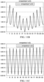
- the first calculation we shall discuss is the average of the absolute difference between the periods of the upstream and downstream signals as they grow and decay, i.e. average(abs(per1-per2)).
- the period of a signal is the inverse of the frequency, so that this calculation provides a value that indicates the difference in the center frequencies of the two signals.
- FIG. 11B provides a graph of this calculation, with the data points shown on the x axis and the magnitude of the difference on the y axis.
- the difference first starts low, rises until the value reaches a peak and starts to decline.
- the various resistance/capacitance values are moved through, the dips in the magnitude drop lower until the value reaches a global minimum near the midpoint of this figure and starts to rise again.
- the global minimum indicates the setting that provides the best match.
- the second calculation averages the absolute difference in each zero crossing for the two signals, i.e., average(abs(zc1-zc2)). This is another method of measuring the difference in the phase of the two signals and thus how closely they match.
- a graph of this second calculation is shown in FIG. 11C .
- Both the first and second calculations can be used when the computing power is not available to calculate the FFT of the signals.
- the second calculation can also clearly indicate the best matching values.
- the third calculation shown is the difference in the maximum amplitude of the two signals, i.e., max(Y1-Y2); the associated graph is shown in FIG. 11D .
- both the calculation of FIG. 11B and the calculation of FIG. 11D can be used, even when stopping the flow is not feasible or desirable.
- This last graph also exhibits a regularity that can be advantageous.
- each parabolic section represents one value of the resistance as the various capacitances are moved through.
- a shortcut can be used to avoid running through the entire range of resistance and capacitance to determine the best values.
- the local minimum in the difference in amplitude calculation i.e., max(Y1-Y2)
- max(Y1-Y2) the local minimum in the difference in amplitude calculation
- FIGS. 12A-B a method of automatically tuning the driver/receiver circuitry of an upstream transducer and a downstream transducer to each other for reciprocal operation in an ultrasonic flowmeter is shown in FIGS. 12A-B .
- Flowchart 1200A illustrates the first part of this method, i.e., determining whether a pair of transducers matches each other.
- the method begins with exchanging (1205) signals between an upstream transducer and a downstream transducer. This exchange of signals is part of the normal operation of the ultrasonic flow meter.
- This operation includes sending a signal from the upstream transducer, which is received at the downstream transducer, and also includes sending a signal from the downstream transducer, which is received at the upstream transducer.
- the maximum amplitude of the upstream signal can be compared (1210) to the maximum amplitude of the downstream signal.
- the center frequency of an FFT of the upstream signal can also be compared (1215) to the center frequency of an FFT of the downstream signal.
- the two comparisons are shown as alternate paths that can be followed to emphasize that the method can be practiced using only one of these comparisons or can use a combination of the two paths. Likewise, these comparisons can be made in any order.
- the two comparisons are examined to determine (1220) whether the two signals match. If the two signals match, no correction is necessary and the method continues to monitor the exchanged signals and to watch for any changes. If the two signals do not match, the mismatch is corrected (1225).
- this correction can be made by adjusting the results of the flow meter's measurements using the detected offset and available temperature information. In at least one embodiment, however, the impedance of the circuit associated with one of the transducers will be adjusted to correct the mismatch, as shown in the following figure.
- the method of flow chart 1200B begins by setting (1230) a first component of the impedance to the first value in a first range of values and setting (1235) a second component of the impedance to the first value in a second range of values.
- the two components of impedance that are adjusted according to an embodiment of the disclosure are resistance and capacitance. Either of these components can be used as the first component while the other component becomes the second.
- the ranges over which each component will be varied can be determined in a conventional manner according to known parameters for these components.
- the value of a data point corresponding to the current values of the first and second components is determined by exchanging (1240) signals between the upstream and downstream transducers and determining (1245) the absolute value of the difference in maximum amplitude of the upstream signal and the downstream signal. In at least one embodiment, the difference in center frequencies of an FFT on each signal is also determined (1247). The method determines (1250) whether a local minimum of the data points has been found. If not, the value of the second component is incremented (1255) to the next value in the range and the value of the corresponding data point is determined. Finding the local minimum requires finding two or more data points.
- the second component is set (1260) to the value corresponding to the local minimum.
- the method continues by incrementing (1265) the first component of impedance to a next value in the first range of values.
- the method exchanges (1270) signals between the upstream and downstream transducers and determines (1275) the absolute value of the difference in maximum amplitude of the upstream signal and the downstream signal.
- the difference in center frequencies of an FFT on each signal is also determined (1277).
- a determination will be made (1280) whether a global minimum in the value of the data points has been located. As before, finding the global minimum requires finding two or more data points. As long as the value of the data points is decreasing, a determination cannot be made about whether the global minimum has been reached. However, after the value of the data points starts increasing, the global minimum can be determined to be the data point having the lowest value.
- the first component is set (1285) to the value corresponding to the global minimum. This completes the method, as the two transducer circuits are now tuned to each other. The normal operation of the flow meter can continue at this point. Comparison of the signals can continue to operate, and further corrections can be applied as necessary.
Landscapes
- Physics & Mathematics (AREA)
- Fluid Mechanics (AREA)
- General Physics & Mathematics (AREA)
- Electromagnetism (AREA)
- Measuring Volume Flow (AREA)
Claims (13)
- Verfahren zum automatischen Abstimmen einer ersten Schaltung, die mit einem Upstream-Wandler UPT (T1) assoziiert ist, und einer zweiten Schaltung, die mit einem Downstream-Wandler DNT (T2) assoziiert ist, für reziproken Betrieb in einem Ultraschalldurchflussmesser, wobei das Verfahren Folgendes umfasst:
Austauschen von Signalen zwischen dem Upstream-Wandler und dem Downstream-Wandler; dadurch gekennzeichnet, dass das Verfahren ferner Folgendes umfasst:Vergleichen jeweiliger maximaler Amplituden eines Upstream-Signals und eines Downstream-Signals; undals Reaktion darauf, dass bestimmt wird, dass die jeweiligen maximalen Amplituden nicht übereinstimmen, Korrigieren der Fehlanpassung;wobei das Korrigieren der Fehlanpassung Anpassen eines Impedanzwerts in der ersten Schaltung und/oder der zweiten Schaltung umfasst. - Verfahren nach Anspruch 1, wobei der Vergleichsschritt ferner Vergleichen jeweiliger Mittenfrequenzen einer schnellen Fourier-Transformation FFT des Upstream-Signals und des Downstream-Signals und als Reaktion darauf, dass bestimmt wird, dass die jeweiligen Mittenfrequenzen nicht übereinstimmen, Korrigieren der Fehlanpassung umfasst.
- Verfahren nach Anspruch 1, wobei das Anpassen des Impedanzwerts Folgendes umfasst: Einstellen einer ersten Komponente der Impedanz auf einen ersten Wert eines ersten Wertebereichs und einer zweiten Komponente der Impedanz auf einen ersten Wert eines zweiten Wertebereichs;Bestimmen eines Werts eines jeweiligen Datenpunkts durch Austauschen von Signalen zwischen dem UPT und dem DNT und Bestimmen des Absolutwerts einer Differenz der maximalen Amplitude des Upstream-Signals und des Downstream-Signals;Inkrementieren der zweiten Komponente auf einen nächsten Wert in dem zweiten Bereich und Bestimmen des Werts des jeweiligen Datenpunkts, wobei das Inkrementieren der zweiten Komponente und das Bestimmen des jeweiligen Datenpunkts fortgesetzt wird, bis ein lokales Minimum in den Datenpunkten bestimmt wird;Einstellen der zweiten Komponente auf einen Wert, der dem lokalen Minimum entspricht;Inkrementieren der ersten Komponente auf einen nächsten Wert in dem ersten Bereich und Bestimmen des Werts des jeweiligen Datenpunkts, wobei das Inkrementieren der ersten Komponente und das Bestimmen des jeweiligen Datenpunkts fortgesetzt wird, bis ein globales Minimum in den Datenpunkten bestimmt wird; undEinstellen der ersten Komponente auf einen Wert, der dem globalen Minimum entspricht.
- Verfahren nach Anspruch 3, wobei das lokale Minimum bestimmt wird, wenn die zweite Komponente auf alle Werte in dem zweiten Bereich eingestellt wurde oder der Wert des jeweiligen Datenpunkts nicht mehr kleiner als ein vorheriger Wert wird, und das globale Minimum bestimmt wird, wenn die erste Komponente auf alle Werte in dem ersten Bereich eingestellt wurde oder der Wert des jeweiligen Datenpunkts nicht mehr kleiner als ein vorheriger Wert wird.
- Verfahren nach Anspruch 4, wobei die erste Komponente ein Widerstand ist und die zweite Komponente eine Kapazität ist.
- Verfahren nach Anspruch 3, wobei das Bestimmen des Werts des jeweiligen Datenpunkts ferner Bestimmen eines Absolutwerts einer Differenz der Mittenfrequenz der FFT des Upstream-Signals und der FFT des Downstream-Signals umfasst.
- Integrierte-Schaltung-Chip (201) zum automatischen Abstimmen einer ersten Schaltung (503), die mit einem Upstream-Wandler UPT (T1) wirkverbunden ist, und einer zweiten Schaltung (509), die mit einem Downstream-Wandler DNT (T2) wirkverbunden ist, für reziproken Betrieb in einem Ultraschalldurchflussmesser, wobei der Integrierte-Schaltung-Chip Folgendes umfasst:einen Mikrocontroller (210), der mit dem UPT und dem DNT wirkverbunden ist, um eine Steuerung des UPT und des DNT bereitzustellen, und ferner dahingehend verbunden ist, ein jeweiliges Signal von sowohl dem UPT als auch dem DNT zu empfangen; undeinen Speicher (216), der mit dem Mikrocontroller wirkverbunden ist, wobei der Speicher Anweisungen enthält, die bei Ausführung durch den Mikrocontroller Folgendes durchführen: Austauschen von Signalen zwischen dem Upstream-Wandler und dem Downstream-Wandler; dadurch gekennzeichnet, dass der Mikrocontroller ferner Folgendes durchführt: Vergleichen jeweiliger maximaler Amplituden eines Upstream-Signals und eines Downstream-Signals; und als Reaktion darauf, dass bestimmt wird, dass die jeweiligen maximalen Amplituden nicht übereinstimmen, Korrigieren der Fehlanpassung;wobei das Korrigieren der Fehlanpassung Anpassen eines Impedanzwerts in der ersten Schaltung und/oder der zweiten Schaltung umfasst.
- Integrierte-Schaltung-Chip nach Anspruch 7, wobei der Speicher ferner Anweisungen enthält, die bei Ausführung durch den Mikrocontroller Folgendes durchführen: Vergleichen jeweiliger Mittenfrequenzen einer schnellen Fourier-Transformation FFT des Upstream-Signals und des Downstream-Signals und als Reaktion darauf, dass bestimmt wird, dass die jeweiligen Mittenfrequenzen nicht übereinstimmen, Korrigieren der Fehlanpassung.
- Integrierte-Schaltung-Chip nach Anspruch 7 oder 8, wobei das Korrigieren der Fehlanpassung Kompensieren der Impedanzfehlanpassung während der digitalen Verarbeitung der Signale umfasst.
- Integrierte-Schaltung-Chip nach Anspruch 7, wobei das Anpassen des Impedanzwerts Folgendes umfasst:Einstellen einer ersten Komponente der Impedanz auf einen ersten Wert eines ersten Wertebereichs und einer zweiten Komponente der Impedanz auf einen ersten Wert eines zweiten Wertebereichs;Bestimmen eines Werts eines jeweiligen Datenpunkts durch Austauschen von Signalen zwischen dem UPT und dem DNT und Bestimmen des Absolutwerts einer Differenz der maximalen Amplitude des Upstream-Signals und des Downstream-Signals;Inkrementieren der zweiten Komponente auf einen nächsten Wert in dem zweiten Bereich und Bestimmen des Werts des jeweiligen Datenpunkts, wobei das Inkrementieren der zweiten Komponente und das Bestimmen des Werts des jeweiligen Datenpunkts fortgesetzt wird, bis ein lokales Minimum in den Datenpunkten bestimmt wird; Einstellen der zweiten Komponente auf einen Wert, der dem lokalen Minimum entspricht;Inkrementieren der ersten Komponente auf einen nächsten Wert in dem ersten Bereich und Bestimmen des Werts des jeweiligen Datenpunkts, wobei das Inkrementieren der ersten Komponente und das Bestimmen des Werts des jeweiligen Datenpunkts fortgesetzt wird, bis ein globales Minimum in den Datenpunkten bestimmt wird; undEinstellen der ersten Komponente auf einen Wert, der dem globalen Minimum entspricht.
- Integrierte-Schaltung-Chip nach Anspruch 10, wobei das lokale Minimum bestimmt wird, wenn die zweite Komponente auf alle Werte in dem zweiten Bereich eingestellt wurde oder der jeweilige Datenpunkt nicht mehr kleiner wird, und das globale Minimum bestimmt wird, wenn die erste Komponente auf alle Werte in dem ersten Bereich eingestellt wurde oder der jeweilige Datenpunkt nicht mehr kleiner wird.
- Integrierte-Schaltung-Chip nach Anspruch 11, wobei die erste Komponente ein Widerstand ist und die zweite Komponente eine Kapazität ist.
- Integrierte-Schaltung-Chip nach Anspruch 11, wobei das Bestimmen des Werts des jeweiligen Datenpunkts ferner Bestimmen eines Absolutwerts einer Differenz der Mittenfrequenz der FFT des Upstream-Signals und der FFT des Downstream-Signals umfasst.
Applications Claiming Priority (2)
| Application Number | Priority Date | Filing Date | Title |
|---|---|---|---|
| US14/862,832 US10006791B2 (en) | 2015-09-23 | 2015-09-23 | Ultrasonic flow meter auto-tuning for reciprocal operation of the meter |
| PCT/US2016/053363 WO2017053743A1 (en) | 2015-09-23 | 2016-09-23 | Ultrasonic flow meter auto-tuning for reciprocal operation of the meter |
Publications (3)
| Publication Number | Publication Date |
|---|---|
| EP3353505A1 EP3353505A1 (de) | 2018-08-01 |
| EP3353505A4 EP3353505A4 (de) | 2018-10-24 |
| EP3353505B1 true EP3353505B1 (de) | 2025-03-12 |
Family
ID=58277041
Family Applications (1)
| Application Number | Title | Priority Date | Filing Date |
|---|---|---|---|
| EP16849714.7A Active EP3353505B1 (de) | 2015-09-23 | 2016-09-23 | Ultraschalldurchflussmesser selbstabstimmung für reziproken betrieb des zählers |
Country Status (5)
| Country | Link |
|---|---|
| US (2) | US10006791B2 (de) |
| EP (1) | EP3353505B1 (de) |
| JP (1) | JP6709846B2 (de) |
| CN (2) | CN107923778B (de) |
| WO (1) | WO2017053743A1 (de) |
Families Citing this family (11)
| Publication number | Priority date | Publication date | Assignee | Title |
|---|---|---|---|---|
| US10006791B2 (en) * | 2015-09-23 | 2018-06-26 | Texas Instruments Incorporated | Ultrasonic flow meter auto-tuning for reciprocal operation of the meter |
| CN106595785B (zh) * | 2017-01-23 | 2019-01-01 | 青岛海威茨仪表有限公司 | 一种对射式小口径超声波流量计 |
| US10960370B2 (en) | 2017-06-07 | 2021-03-30 | Omni International, Inc. | Ultrasonic homogenization device with closed-loop amplitude control |
| US12449290B2 (en) * | 2018-12-26 | 2025-10-21 | Texas Instruments Incorporated | Dynamic temperature calibration of ultrasonic transducers |
| CN111366204B (zh) * | 2020-02-28 | 2022-03-08 | 龙芯中科(金华)技术有限公司 | 流量测量电路和方法 |
| EP3882579B1 (de) * | 2020-03-20 | 2023-09-20 | Sciosense B.V. | Ultraschalldurchflussmesser und verfahren zur ultraschalldurchflussmessung |
| CN114795397B (zh) * | 2021-01-28 | 2025-03-25 | 上海逸思医疗科技股份有限公司 | 超声换能器的电流校准方法、装置和超声波手术系统 |
| CN116257105B (zh) * | 2021-12-10 | 2025-07-25 | 圣邦微电子(北京)股份有限公司 | 一种降低振荡的带隙基准源修调电路 |
| CN114184245B (zh) * | 2022-02-16 | 2022-04-26 | 青岛积成电子股份有限公司 | 用于燃气计量的超声波换能器自动配对方法 |
| CN114184246A (zh) * | 2022-02-16 | 2022-03-15 | 青岛积成电子股份有限公司 | 一种用于燃气计量的超声波换能器分档方法 |
| CN116256015B (zh) * | 2023-03-17 | 2025-07-18 | 中煤科工集团重庆研究院有限公司 | 一种超声波巷道、管道流速流量测量实时自校准方法 |
Family Cites Families (40)
| Publication number | Priority date | Publication date | Assignee | Title |
|---|---|---|---|---|
| US4221128A (en) * | 1978-09-29 | 1980-09-09 | Neil Brown Instruments Systems, Inc. | Acoustic current meter |
| US4425715A (en) | 1979-06-25 | 1984-01-17 | Hydril Company | Thread gaging apparatus and method |
| DE3025788C2 (de) | 1980-07-08 | 1985-07-04 | Danfoss A/S, Nordborg | Ultraschall-Meßgerät |
| GB2237639B (en) * | 1989-10-31 | 1994-07-06 | British Gas Plc | Measurement system |
| DE59100815D1 (de) | 1991-02-08 | 1994-02-17 | Flowtec Ag | Betriebsschaltung für Ultraschall-Volumendurchflussmessgeräte. |
| US5115672A (en) * | 1991-02-11 | 1992-05-26 | Westinghouse Electric Corp. | System and method for valve monitoring using pipe-mounted ultrasonic transducers |
| US5777892A (en) * | 1992-03-30 | 1998-07-07 | Isco, Inc. | Doppler shift velocity measuring system with correction factors |
| US5337611A (en) * | 1992-12-02 | 1994-08-16 | Electric Power Research Institute | Method of simulating ultrasonic inspection of flaws |
| WO1994017371A1 (en) | 1993-01-30 | 1994-08-04 | G.Kromschröder Aktiengesellschaft | Fluid flow meter |
| US5512843A (en) * | 1993-11-15 | 1996-04-30 | Martin Marietta Energy Systems, Inc. | Monitoring method and apparatus using high-frequency carrier |
| US6005827A (en) * | 1995-03-02 | 1999-12-21 | Acuson Corporation | Ultrasonic harmonic imaging system and method |
| US6104670A (en) * | 1995-03-02 | 2000-08-15 | Acuson Corporation | Ultrasonic harmonic imaging system and method |
| US5964706A (en) * | 1998-03-18 | 1999-10-12 | General Electric Company | Method and apparatus for pulsed doppler imaging using coded excitation on transmit and pulse compression on receive |
| AUPP318098A0 (en) * | 1998-04-24 | 1998-05-21 | Commonwealth Scientific And Industrial Research Organisation | A liquid flow meter |
| DE10084306B4 (de) * | 1999-03-01 | 2006-02-02 | H & B System Co., Ltd. | Ultraschallerfassungsgerät und ein dieses verwendendes Ultraschallerfassungsverfahren |
| TW482892B (en) * | 1999-05-11 | 2002-04-11 | Matsushita Electric Industrial Co Ltd | Flow rate measuring device |
| DK199901477A (da) * | 1999-10-14 | 2001-04-15 | Danfoss As | Sende- og modtagekredsløb for ultralydsflowmåler |
| US7088765B1 (en) * | 2000-03-15 | 2006-08-08 | Ndsu Research Foundation | Vector calibration system |
| US6925891B2 (en) | 2002-04-30 | 2005-08-09 | Matsushita Electric Industrial Co., Ltd. | Ultrasonic flowmeter and method of measuring flow volume |
| JP3669580B2 (ja) * | 2002-05-24 | 2005-07-06 | 学校法人慶應義塾 | 超音波流速分布及び流量計 |
| EP1646864B1 (de) * | 2003-07-18 | 2018-11-07 | Rosemount Inc. | Prozessdiagnostik |
| WO2005043771A1 (en) * | 2003-10-23 | 2005-05-12 | American Technology Corporation | Method of adusting linear parameters of a parametric ultrasonic signal to reduce non-linearities in decoupled audio output waves and system including same |
| US7117104B2 (en) * | 2004-06-28 | 2006-10-03 | Celerity, Inc. | Ultrasonic liquid flow controller |
| WO2006004986A1 (en) | 2004-06-29 | 2006-01-12 | Pharmix Corporation | Estimating the accuracy of molecular property models and predictions |
| HUP0500553A2 (en) * | 2005-06-02 | 2007-02-28 | N Sandor K | Method and arrangement for dynamic determination of instability (zero point drift) of coriolis and impedance type mass flowmeters |
| JP4610465B2 (ja) | 2005-07-29 | 2011-01-12 | 富士機工株式会社 | ステアリングシャフト |
| DE102005038599A1 (de) * | 2005-08-16 | 2007-02-22 | Robert Bosch Gmbh | Ultraschallmesseinheit mit integrierter Feuchteermittlung |
| JP2007155574A (ja) * | 2005-12-07 | 2007-06-21 | Ricoh Elemex Corp | 超音波流量計 |
| US7532992B2 (en) * | 2006-01-20 | 2009-05-12 | Teledyne Isco, Inc. | Measuring apparatuses and methods of using them |
| US7966882B2 (en) * | 2008-04-23 | 2011-06-28 | Battelle Memorial Institute | Self-calibrating method for measuring the density and velocity of sound from two reflections of ultrasound at a solid-liquid interface |
| EP2383550A1 (de) * | 2010-04-28 | 2011-11-02 | Miitors ApS | Ultraschall-Durchflussmesser |
| CN104169692A (zh) * | 2011-12-02 | 2014-11-26 | 卡姆鲁普股份有限公司 | 具有数字化欠采样流量测量的超声波流量计 |
| US9513372B2 (en) * | 2013-01-22 | 2016-12-06 | Schlumberger Technology Corporation | Automatic processing of ultrasonic data |
| WO2015031180A1 (en) * | 2013-08-27 | 2015-03-05 | Infosense, Inc. | Method and apparatus for valve position state estimation |
| NO20131375A1 (no) | 2013-10-16 | 2015-04-17 | Roxar Flow Measurement As | Scale monitoring |
| CN103948402B (zh) * | 2014-05-13 | 2016-04-13 | 中国科学院深圳先进技术研究院 | 肿瘤超声成像特征提取方法和系统 |
| CN104848973A (zh) * | 2015-04-12 | 2015-08-19 | 北京工业大学 | 基于超声导波陷频的钢索拉力测量方法 |
| US10309813B2 (en) * | 2015-05-15 | 2019-06-04 | Reliance Worldwide Corporation | Method and system for fluid flow rate measurement |
| US10006791B2 (en) * | 2015-09-23 | 2018-06-26 | Texas Instruments Incorporated | Ultrasonic flow meter auto-tuning for reciprocal operation of the meter |
| JP6678022B2 (ja) * | 2015-12-11 | 2020-04-08 | 古野電気株式会社 | 探知装置、水中探知装置、及びレーダ装置 |
-
2015
- 2015-09-23 US US14/862,832 patent/US10006791B2/en active Active
-
2016
- 2016-09-23 EP EP16849714.7A patent/EP3353505B1/de active Active
- 2016-09-23 CN CN201680047988.4A patent/CN107923778B/zh active Active
- 2016-09-23 WO PCT/US2016/053363 patent/WO2017053743A1/en not_active Ceased
- 2016-09-23 CN CN202011129887.6A patent/CN112504368B/zh active Active
- 2016-09-23 JP JP2018515626A patent/JP6709846B2/ja active Active
-
2018
- 2018-05-23 US US15/987,129 patent/US10495502B2/en active Active
Also Published As
| Publication number | Publication date |
|---|---|
| EP3353505A1 (de) | 2018-08-01 |
| JP6709846B2 (ja) | 2020-06-17 |
| JP2018528434A (ja) | 2018-09-27 |
| US20170082471A1 (en) | 2017-03-23 |
| US20180266860A1 (en) | 2018-09-20 |
| CN107923778B (zh) | 2020-11-10 |
| US10495502B2 (en) | 2019-12-03 |
| CN112504368B (zh) | 2024-07-05 |
| WO2017053743A1 (en) | 2017-03-30 |
| US10006791B2 (en) | 2018-06-26 |
| EP3353505A4 (de) | 2018-10-24 |
| CN107923778A (zh) | 2018-04-17 |
| CN112504368A (zh) | 2021-03-16 |
Similar Documents
| Publication | Publication Date | Title |
|---|---|---|
| EP3353505B1 (de) | Ultraschalldurchflussmesser selbstabstimmung für reziproken betrieb des zählers | |
| US10775212B2 (en) | Ultrasonic flow meter | |
| EP3042155B1 (de) | Ultraschalldurchflussmesser | |
| US20090066440A1 (en) | Method for automatic impedance matching for a radiofrequency circuit and transmission or reception system with automatic matching | |
| CN105841762B (zh) | 超声波水表的流量计量方法和系统 | |
| EP2000784A1 (de) | Ultraschalldurchflussmesser mit Temperaturkompensation | |
| EP3576429A1 (de) | Ultraschallvorrichtung | |
| CN105490760B (zh) | 用于至少提供射频信号参数的变频传感器和系统 | |
| US6829948B2 (en) | Flow meter | |
| US20210003436A1 (en) | Time-of-flight generating circuit and chip, flow meter and method of the same | |
| CN109581062A (zh) | 用于示波器校准仪探头的高精度阻抗测量系统 | |
| US20050075076A1 (en) | Method and apparatus for measuring impedance of electrical component under high interference conditions | |
| US7834641B1 (en) | Phase-gain calibration of impedance/admittance meter | |
| JP4141961B2 (ja) | システム校正されたベクトル・ネットワークアナライザの実効指向性および/または実効ソースポート整合性の測定方法、校正標準セットの作成方法 | |
| Staroszczyk | Problems in real-time wide band identification of power systems | |
| JP2003279396A (ja) | 超音波流量計 | |
| CN106053945B (zh) | 一种短时s函数史密斯圆图分析装置及方法 | |
| US20190089306A1 (en) | Flow detection with quadrature demodulation | |
| JP6330049B2 (ja) | ネットワーク・アナライザの較正のためにシステム誤差及びパワー値を求める方法、較正ユニット及びシステム | |
| Barrera-Figueroa et al. | On experimental determination of the free-field correction of laboratory standard microphones at normal incidence | |
| JP2001188074A (ja) | インピーダンス測定方法及び装置 | |
| GB2506912A (en) | Inductive Probe Testing Apparatus | |
| Olsen | Heat conduction correction in reciprocity calibration of laboratory standard microphones | |
| Keprt et al. | Primary calibration of acoustic emission sensors | |
| CN121741301A (zh) | 一种基于iq解调计算阻抗的测量及校准方法 |
Legal Events
| Date | Code | Title | Description |
|---|---|---|---|
| STAA | Information on the status of an ep patent application or granted ep patent |
Free format text: STATUS: THE INTERNATIONAL PUBLICATION HAS BEEN MADE |
|
| PUAI | Public reference made under article 153(3) epc to a published international application that has entered the european phase |
Free format text: ORIGINAL CODE: 0009012 |
|
| STAA | Information on the status of an ep patent application or granted ep patent |
Free format text: STATUS: REQUEST FOR EXAMINATION WAS MADE |
|
| 17P | Request for examination filed |
Effective date: 20180423 |
|
| AK | Designated contracting states |
Kind code of ref document: A1 Designated state(s): AL AT BE BG CH CY CZ DE DK EE ES FI FR GB GR HR HU IE IS IT LI LT LU LV MC MK MT NL NO PL PT RO RS SE SI SK SM TR |
|
| AX | Request for extension of the european patent |
Extension state: BA ME |
|
| RIC1 | Information provided on ipc code assigned before grant |
Ipc: G01F 1/66 20060101AFI20180913BHEP Ipc: G01F 25/00 20060101ALI20180913BHEP |
|
| A4 | Supplementary search report drawn up and despatched |
Effective date: 20180920 |
|
| DAV | Request for validation of the european patent (deleted) | ||
| DAX | Request for extension of the european patent (deleted) | ||
| STAA | Information on the status of an ep patent application or granted ep patent |
Free format text: STATUS: EXAMINATION IS IN PROGRESS |
|
| 17Q | First examination report despatched |
Effective date: 20211013 |
|
| REG | Reference to a national code |
Ref country code: DE Ref legal event code: R079 Free format text: PREVIOUS MAIN CLASS: G01F0001660000 Ipc: G01F0001667000 Ref document number: 602016091549 Country of ref document: DE |
|
| GRAP | Despatch of communication of intention to grant a patent |
Free format text: ORIGINAL CODE: EPIDOSNIGR1 |
|
| STAA | Information on the status of an ep patent application or granted ep patent |
Free format text: STATUS: GRANT OF PATENT IS INTENDED |
|
| RIC1 | Information provided on ipc code assigned before grant |
Ipc: G01F 25/10 20220101ALI20241011BHEP Ipc: G01F 1/667 20220101AFI20241011BHEP |
|
| INTG | Intention to grant announced |
Effective date: 20241023 |
|
| GRAS | Grant fee paid |
Free format text: ORIGINAL CODE: EPIDOSNIGR3 |
|
| GRAL | Information related to payment of fee for publishing/printing deleted |
Free format text: ORIGINAL CODE: EPIDOSDIGR3 |
|
| GRAS | Grant fee paid |
Free format text: ORIGINAL CODE: EPIDOSNIGR3 |
|
| GRAA | (expected) grant |
Free format text: ORIGINAL CODE: 0009210 |
|
| STAA | Information on the status of an ep patent application or granted ep patent |
Free format text: STATUS: THE PATENT HAS BEEN GRANTED |
|
| P01 | Opt-out of the competence of the unified patent court (upc) registered |
Free format text: CASE NUMBER: APP_2102/2025 Effective date: 20250113 |
|
| AK | Designated contracting states |
Kind code of ref document: B1 Designated state(s): AL AT BE BG CH CY CZ DE DK EE ES FI FR GB GR HR HU IE IS IT LI LT LU LV MC MK MT NL NO PL PT RO RS SE SI SK SM TR |
|
| REG | Reference to a national code |
Ref country code: GB Ref legal event code: FG4D |
|
| REG | Reference to a national code |
Ref country code: CH Ref legal event code: EP |
|
| REG | Reference to a national code |
Ref country code: DE Ref legal event code: R096 Ref document number: 602016091549 Country of ref document: DE |
|
| REG | Reference to a national code |
Ref country code: IE Ref legal event code: FG4D |
|
| PG25 | Lapsed in a contracting state [announced via postgrant information from national office to epo] |
Ref country code: RS Free format text: LAPSE BECAUSE OF FAILURE TO SUBMIT A TRANSLATION OF THE DESCRIPTION OR TO PAY THE FEE WITHIN THE PRESCRIBED TIME-LIMIT Effective date: 20250612 |
|
| PG25 | Lapsed in a contracting state [announced via postgrant information from national office to epo] |
Ref country code: FI Free format text: LAPSE BECAUSE OF FAILURE TO SUBMIT A TRANSLATION OF THE DESCRIPTION OR TO PAY THE FEE WITHIN THE PRESCRIBED TIME-LIMIT Effective date: 20250312 |
|
| PG25 | Lapsed in a contracting state [announced via postgrant information from national office to epo] |
Ref country code: ES Free format text: LAPSE BECAUSE OF FAILURE TO SUBMIT A TRANSLATION OF THE DESCRIPTION OR TO PAY THE FEE WITHIN THE PRESCRIBED TIME-LIMIT Effective date: 20250312 |
|
| REG | Reference to a national code |
Ref country code: LT Ref legal event code: MG9D |
|
| PG25 | Lapsed in a contracting state [announced via postgrant information from national office to epo] |
Ref country code: NO Free format text: LAPSE BECAUSE OF FAILURE TO SUBMIT A TRANSLATION OF THE DESCRIPTION OR TO PAY THE FEE WITHIN THE PRESCRIBED TIME-LIMIT Effective date: 20250612 |
|
| PG25 | Lapsed in a contracting state [announced via postgrant information from national office to epo] |
Ref country code: HR Free format text: LAPSE BECAUSE OF FAILURE TO SUBMIT A TRANSLATION OF THE DESCRIPTION OR TO PAY THE FEE WITHIN THE PRESCRIBED TIME-LIMIT Effective date: 20250312 |
|
| REG | Reference to a national code |
Ref country code: NL Ref legal event code: MP Effective date: 20250312 |
|
| PG25 | Lapsed in a contracting state [announced via postgrant information from national office to epo] |
Ref country code: LV Free format text: LAPSE BECAUSE OF FAILURE TO SUBMIT A TRANSLATION OF THE DESCRIPTION OR TO PAY THE FEE WITHIN THE PRESCRIBED TIME-LIMIT Effective date: 20250312 |
|
| PG25 | Lapsed in a contracting state [announced via postgrant information from national office to epo] |
Ref country code: GR Free format text: LAPSE BECAUSE OF FAILURE TO SUBMIT A TRANSLATION OF THE DESCRIPTION OR TO PAY THE FEE WITHIN THE PRESCRIBED TIME-LIMIT Effective date: 20250613 Ref country code: BG Free format text: LAPSE BECAUSE OF FAILURE TO SUBMIT A TRANSLATION OF THE DESCRIPTION OR TO PAY THE FEE WITHIN THE PRESCRIBED TIME-LIMIT Effective date: 20250312 |
|
| REG | Reference to a national code |
Ref country code: AT Ref legal event code: MK05 Ref document number: 1775333 Country of ref document: AT Kind code of ref document: T Effective date: 20250312 |
|
| PG25 | Lapsed in a contracting state [announced via postgrant information from national office to epo] |
Ref country code: NL Free format text: LAPSE BECAUSE OF FAILURE TO SUBMIT A TRANSLATION OF THE DESCRIPTION OR TO PAY THE FEE WITHIN THE PRESCRIBED TIME-LIMIT Effective date: 20250312 |
|
| PG25 | Lapsed in a contracting state [announced via postgrant information from national office to epo] |
Ref country code: SE Free format text: LAPSE BECAUSE OF FAILURE TO SUBMIT A TRANSLATION OF THE DESCRIPTION OR TO PAY THE FEE WITHIN THE PRESCRIBED TIME-LIMIT Effective date: 20250312 |
|
| PG25 | Lapsed in a contracting state [announced via postgrant information from national office to epo] |
Ref country code: SM Free format text: LAPSE BECAUSE OF FAILURE TO SUBMIT A TRANSLATION OF THE DESCRIPTION OR TO PAY THE FEE WITHIN THE PRESCRIBED TIME-LIMIT Effective date: 20250312 |
|
| PG25 | Lapsed in a contracting state [announced via postgrant information from national office to epo] |
Ref country code: PT Free format text: LAPSE BECAUSE OF FAILURE TO SUBMIT A TRANSLATION OF THE DESCRIPTION OR TO PAY THE FEE WITHIN THE PRESCRIBED TIME-LIMIT Effective date: 20250714 |
|
| PGFP | Annual fee paid to national office [announced via postgrant information from national office to epo] |
Ref country code: DE Payment date: 20250820 Year of fee payment: 10 |
|
| PG25 | Lapsed in a contracting state [announced via postgrant information from national office to epo] |
Ref country code: PL Free format text: LAPSE BECAUSE OF FAILURE TO SUBMIT A TRANSLATION OF THE DESCRIPTION OR TO PAY THE FEE WITHIN THE PRESCRIBED TIME-LIMIT Effective date: 20250312 Ref country code: IT Free format text: LAPSE BECAUSE OF FAILURE TO SUBMIT A TRANSLATION OF THE DESCRIPTION OR TO PAY THE FEE WITHIN THE PRESCRIBED TIME-LIMIT Effective date: 20250312 |
|
| PGFP | Annual fee paid to national office [announced via postgrant information from national office to epo] |
Ref country code: GB Payment date: 20250822 Year of fee payment: 10 |
|
| PG25 | Lapsed in a contracting state [announced via postgrant information from national office to epo] |
Ref country code: AT Free format text: LAPSE BECAUSE OF FAILURE TO SUBMIT A TRANSLATION OF THE DESCRIPTION OR TO PAY THE FEE WITHIN THE PRESCRIBED TIME-LIMIT Effective date: 20250312 |
|
| PGFP | Annual fee paid to national office [announced via postgrant information from national office to epo] |
Ref country code: FR Payment date: 20250820 Year of fee payment: 10 |
|
| PG25 | Lapsed in a contracting state [announced via postgrant information from national office to epo] |
Ref country code: EE Free format text: LAPSE BECAUSE OF FAILURE TO SUBMIT A TRANSLATION OF THE DESCRIPTION OR TO PAY THE FEE WITHIN THE PRESCRIBED TIME-LIMIT Effective date: 20250312 Ref country code: CZ Free format text: LAPSE BECAUSE OF FAILURE TO SUBMIT A TRANSLATION OF THE DESCRIPTION OR TO PAY THE FEE WITHIN THE PRESCRIBED TIME-LIMIT Effective date: 20250312 |
|
| PG25 | Lapsed in a contracting state [announced via postgrant information from national office to epo] |
Ref country code: RO Free format text: LAPSE BECAUSE OF FAILURE TO SUBMIT A TRANSLATION OF THE DESCRIPTION OR TO PAY THE FEE WITHIN THE PRESCRIBED TIME-LIMIT Effective date: 20250312 |
|
| PG25 | Lapsed in a contracting state [announced via postgrant information from national office to epo] |
Ref country code: SK Free format text: LAPSE BECAUSE OF FAILURE TO SUBMIT A TRANSLATION OF THE DESCRIPTION OR TO PAY THE FEE WITHIN THE PRESCRIBED TIME-LIMIT Effective date: 20250312 |
|
| PG25 | Lapsed in a contracting state [announced via postgrant information from national office to epo] |
Ref country code: IS Free format text: LAPSE BECAUSE OF FAILURE TO SUBMIT A TRANSLATION OF THE DESCRIPTION OR TO PAY THE FEE WITHIN THE PRESCRIBED TIME-LIMIT Effective date: 20250712 |
|
| REG | Reference to a national code |
Ref country code: DE Ref legal event code: R097 Ref document number: 602016091549 Country of ref document: DE |
|
| PG25 | Lapsed in a contracting state [announced via postgrant information from national office to epo] |
Ref country code: DK Free format text: LAPSE BECAUSE OF FAILURE TO SUBMIT A TRANSLATION OF THE DESCRIPTION OR TO PAY THE FEE WITHIN THE PRESCRIBED TIME-LIMIT Effective date: 20250312 |
|
| PLBE | No opposition filed within time limit |
Free format text: ORIGINAL CODE: 0009261 |
|
| STAA | Information on the status of an ep patent application or granted ep patent |
Free format text: STATUS: NO OPPOSITION FILED WITHIN TIME LIMIT |
|
| REG | Reference to a national code |
Ref country code: CH Ref legal event code: L10 Free format text: ST27 STATUS EVENT CODE: U-0-0-L10-L00 (AS PROVIDED BY THE NATIONAL OFFICE) Effective date: 20260121 |
|
| 26N | No opposition filed |
Effective date: 20251215 |