EP3355998B1 - Trampolin - Google Patents
Trampolin Download PDFInfo
- Publication number
- EP3355998B1 EP3355998B1 EP16774950.6A EP16774950A EP3355998B1 EP 3355998 B1 EP3355998 B1 EP 3355998B1 EP 16774950 A EP16774950 A EP 16774950A EP 3355998 B1 EP3355998 B1 EP 3355998B1
- Authority
- EP
- European Patent Office
- Prior art keywords
- guide
- frame
- inner piece
- trampoline according
- trampoline
- Prior art date
- Legal status (The legal status is an assumption and is not a legal conclusion. Google has not performed a legal analysis and makes no representation as to the accuracy of the status listed.)
- Active
Links
Images


Classifications
-
- A—HUMAN NECESSITIES
- A63—SPORTS; GAMES; AMUSEMENTS
- A63B—APPARATUS FOR PHYSICAL TRAINING, GYMNASTICS, SWIMMING, CLIMBING, OR FENCING; BALL GAMES; TRAINING EQUIPMENT
- A63B5/00—Apparatus for jumping
- A63B5/11—Trampolines
-
- A—HUMAN NECESSITIES
- A63—SPORTS; GAMES; AMUSEMENTS
- A63B—APPARATUS FOR PHYSICAL TRAINING, GYMNASTICS, SWIMMING, CLIMBING, OR FENCING; BALL GAMES; TRAINING EQUIPMENT
- A63B21/00—Exercising apparatus for developing or strengthening the muscles or joints of the body by working against a counterforce, with or without measuring devices
- A63B21/40—Interfaces with the user related to strength training; Details thereof
- A63B21/4027—Specific exercise interfaces
- A63B21/4033—Handles, pedals, bars or platforms
- A63B21/4035—Handles, pedals, bars or platforms for operation by hand
-
- F—MECHANICAL ENGINEERING; LIGHTING; HEATING; WEAPONS; BLASTING
- F16—ENGINEERING ELEMENTS AND UNITS; GENERAL MEASURES FOR PRODUCING AND MAINTAINING EFFECTIVE FUNCTIONING OF MACHINES OR INSTALLATIONS; THERMAL INSULATION IN GENERAL
- F16B—DEVICES FOR FASTENING OR SECURING CONSTRUCTIONAL ELEMENTS OR MACHINE PARTS TOGETHER, e.g. NAILS, BOLTS, CIRCLIPS, CLAMPS, CLIPS OR WEDGES; JOINTS OR JOINTING
- F16B2/00—Friction-grip releasable fastenings
- F16B2/02—Clamps, i.e. with gripping action effected by positive means other than the inherent resistance to deformation of the material of the fastening
- F16B2/06—Clamps, i.e. with gripping action effected by positive means other than the inherent resistance to deformation of the material of the fastening external, i.e. with contracting action
- F16B2/065—Clamps, i.e. with gripping action effected by positive means other than the inherent resistance to deformation of the material of the fastening external, i.e. with contracting action using screw-thread elements
-
- F—MECHANICAL ENGINEERING; LIGHTING; HEATING; WEAPONS; BLASTING
- F16—ENGINEERING ELEMENTS AND UNITS; GENERAL MEASURES FOR PRODUCING AND MAINTAINING EFFECTIVE FUNCTIONING OF MACHINES OR INSTALLATIONS; THERMAL INSULATION IN GENERAL
- F16B—DEVICES FOR FASTENING OR SECURING CONSTRUCTIONAL ELEMENTS OR MACHINE PARTS TOGETHER, e.g. NAILS, BOLTS, CIRCLIPS, CLAMPS, CLIPS OR WEDGES; JOINTS OR JOINTING
- F16B2/00—Friction-grip releasable fastenings
- F16B2/02—Clamps, i.e. with gripping action effected by positive means other than the inherent resistance to deformation of the material of the fastening
- F16B2/06—Clamps, i.e. with gripping action effected by positive means other than the inherent resistance to deformation of the material of the fastening external, i.e. with contracting action
- F16B2/12—Clamps, i.e. with gripping action effected by positive means other than the inherent resistance to deformation of the material of the fastening external, i.e. with contracting action using sliding jaws
-
- F—MECHANICAL ENGINEERING; LIGHTING; HEATING; WEAPONS; BLASTING
- F16—ENGINEERING ELEMENTS AND UNITS; GENERAL MEASURES FOR PRODUCING AND MAINTAINING EFFECTIVE FUNCTIONING OF MACHINES OR INSTALLATIONS; THERMAL INSULATION IN GENERAL
- F16B—DEVICES FOR FASTENING OR SECURING CONSTRUCTIONAL ELEMENTS OR MACHINE PARTS TOGETHER, e.g. NAILS, BOLTS, CIRCLIPS, CLAMPS, CLIPS OR WEDGES; JOINTS OR JOINTING
- F16B2/00—Friction-grip releasable fastenings
- F16B2/02—Clamps, i.e. with gripping action effected by positive means other than the inherent resistance to deformation of the material of the fastening
- F16B2/18—Clamps, i.e. with gripping action effected by positive means other than the inherent resistance to deformation of the material of the fastening using cams, levers, eccentrics, or toggles
- F16B2/185—Clamps, i.e. with gripping action effected by positive means other than the inherent resistance to deformation of the material of the fastening using cams, levers, eccentrics, or toggles using levers
-
- F—MECHANICAL ENGINEERING; LIGHTING; HEATING; WEAPONS; BLASTING
- F16—ENGINEERING ELEMENTS AND UNITS; GENERAL MEASURES FOR PRODUCING AND MAINTAINING EFFECTIVE FUNCTIONING OF MACHINES OR INSTALLATIONS; THERMAL INSULATION IN GENERAL
- F16B—DEVICES FOR FASTENING OR SECURING CONSTRUCTIONAL ELEMENTS OR MACHINE PARTS TOGETHER, e.g. NAILS, BOLTS, CIRCLIPS, CLAMPS, CLIPS OR WEDGES; JOINTS OR JOINTING
- F16B7/00—Connections of rods or tubes, e.g. of non-circular section, mutually, including resilient connections
- F16B7/04—Clamping or clipping connections
- F16B7/044—Clamping or clipping connections for rods or tubes being in angled relationship
- F16B7/0446—Clamping or clipping connections for rods or tubes being in angled relationship for tubes using the innerside thereof
- F16B7/0453—Clamping or clipping connections for rods or tubes being in angled relationship for tubes using the innerside thereof the tubes being drawn towards each other
-
- F—MECHANICAL ENGINEERING; LIGHTING; HEATING; WEAPONS; BLASTING
- F16—ENGINEERING ELEMENTS AND UNITS; GENERAL MEASURES FOR PRODUCING AND MAINTAINING EFFECTIVE FUNCTIONING OF MACHINES OR INSTALLATIONS; THERMAL INSULATION IN GENERAL
- F16B—DEVICES FOR FASTENING OR SECURING CONSTRUCTIONAL ELEMENTS OR MACHINE PARTS TOGETHER, e.g. NAILS, BOLTS, CIRCLIPS, CLAMPS, CLIPS OR WEDGES; JOINTS OR JOINTING
- F16B7/00—Connections of rods or tubes, e.g. of non-circular section, mutually, including resilient connections
- F16B7/10—Telescoping systems
- F16B7/14—Telescoping systems locking in intermediate non-discrete positions
- F16B7/1454—Telescoping systems locking in intermediate non-discrete positions with a clamp locking the telescoping members by swinging a handle provided with a locking cam
-
- F—MECHANICAL ENGINEERING; LIGHTING; HEATING; WEAPONS; BLASTING
- F16—ENGINEERING ELEMENTS AND UNITS; GENERAL MEASURES FOR PRODUCING AND MAINTAINING EFFECTIVE FUNCTIONING OF MACHINES OR INSTALLATIONS; THERMAL INSULATION IN GENERAL
- F16B—DEVICES FOR FASTENING OR SECURING CONSTRUCTIONAL ELEMENTS OR MACHINE PARTS TOGETHER, e.g. NAILS, BOLTS, CIRCLIPS, CLAMPS, CLIPS OR WEDGES; JOINTS OR JOINTING
- F16B7/00—Connections of rods or tubes, e.g. of non-circular section, mutually, including resilient connections
- F16B7/10—Telescoping systems
- F16B7/14—Telescoping systems locking in intermediate non-discrete positions
- F16B7/1472—Telescoping systems locking in intermediate non-discrete positions with a clamping screw perpendicular to the axis of the telescoping members
-
- A—HUMAN NECESSITIES
- A63—SPORTS; GAMES; AMUSEMENTS
- A63B—APPARATUS FOR PHYSICAL TRAINING, GYMNASTICS, SWIMMING, CLIMBING, OR FENCING; BALL GAMES; TRAINING EQUIPMENT
- A63B21/00—Exercising apparatus for developing or strengthening the muscles or joints of the body by working against a counterforce, with or without measuring devices
- A63B21/02—Exercising apparatus for developing or strengthening the muscles or joints of the body by working against a counterforce, with or without measuring devices using resilient force-resisters
- A63B21/023—Wound springs
-
- A—HUMAN NECESSITIES
- A63—SPORTS; GAMES; AMUSEMENTS
- A63B—APPARATUS FOR PHYSICAL TRAINING, GYMNASTICS, SWIMMING, CLIMBING, OR FENCING; BALL GAMES; TRAINING EQUIPMENT
- A63B21/00—Exercising apparatus for developing or strengthening the muscles or joints of the body by working against a counterforce, with or without measuring devices
- A63B21/02—Exercising apparatus for developing or strengthening the muscles or joints of the body by working against a counterforce, with or without measuring devices using resilient force-resisters
- A63B21/055—Exercising apparatus for developing or strengthening the muscles or joints of the body by working against a counterforce, with or without measuring devices using resilient force-resisters extension element type
- A63B21/0552—Elastic ropes or bands
-
- A—HUMAN NECESSITIES
- A63—SPORTS; GAMES; AMUSEMENTS
- A63B—APPARATUS FOR PHYSICAL TRAINING, GYMNASTICS, SWIMMING, CLIMBING, OR FENCING; BALL GAMES; TRAINING EQUIPMENT
- A63B2225/00—Miscellaneous features of sport apparatus, devices or equipment
- A63B2225/09—Adjustable dimensions
- A63B2225/093—Height
-
- A—HUMAN NECESSITIES
- A63—SPORTS; GAMES; AMUSEMENTS
- A63B—APPARATUS FOR PHYSICAL TRAINING, GYMNASTICS, SWIMMING, CLIMBING, OR FENCING; BALL GAMES; TRAINING EQUIPMENT
- A63B2225/00—Miscellaneous features of sport apparatus, devices or equipment
- A63B2225/68—Miscellaneous features of sport apparatus, devices or equipment with article holders
- A63B2225/685—Miscellaneous features of sport apparatus, devices or equipment with article holders for electronic devices, e.g. phone, PDA, GPS device, notebook
Definitions
- the invention relates to a trampoline with the features of patent claim 1.
- the invention is particularly aimed at so-called mini-trampolines, which are also called fitness trampolines. These are smaller trampolines with a maximum diameter of 2 to 3 meters that are used in physiotherapy and fitness.
- the jumping mat is attached to the frame via spiral springs.
- the jumping bed has, for example, a bracket or an eyelet as a receiving device, which is attached to the jumping bed by means of a loop and into which a spiral spring engages.
- the spiral spring is hooked into the frame on the other side.
- a trampoline with a spring suspension provides significant acceleration forces.
- One or more elastic rope rings or (open) ropes are used with the bungee cord suspension, which connect the jumping mat to the frame.
- the receiving device can be designed as a hook element into which a suspension is hung in each case.
- a loop through which a rope is pulled that connects the jumping mat to the frame can also be considered.
- the greater elasticity of such a rubber cable suspension ensures that the body brakes "softer" and in this respect not only protects the joints, but also lengthens the muscular stress and relief phases when jumping, which has advantageous training effects.
- the invention is directed both to trampolines with spring suspensions and to trampolines in which the suspension is designed as an elastic rope or elastic rope ring.
- the invention can be used with any type of trampoline, regardless of the type of suspension of the jumping mat and the geometry of the frame.
- trampolines have a frame from which legs extend.
- the legs ensure that the frame is at a certain distance from the ground when the trampoline is set up. This ensures that the jumping mat can move towards the ground when jumping.
- the frame consists of a tube that is bent to create the frame.
- the handrail is used for a secure hold on the trampoline, with the handrail generally having handles extending laterally from the handrail at its free end, which the user can hold on to during the exercises.
- a trampoline is known in which the support rod is attached to one leg of the trampoline via an intermediate piece.
- the handrail is secured by two side braces that connect the lower end of the handrail to the adjacent legs of the trampoline.
- the known construction is stable. However, it requires a high cost of materials. In addition, the assembly is complex.
- a trampoline is known with a handrail for holding a safety net.
- the support rod is held by a guide in a height-adjustable manner on one leg of the trampoline, with the guide clasping and fixing both the respective leg and the support rod.
- a rack with a frame is known to which musical instruments such as a cymbal can be attached with a rod.
- the rod is received in a guide that is attached to the frame.
- a trampoline is known from practice, on the frame of which a clamping device is welded.
- the support rod is accommodated in the clamping device so that it can be moved longitudinally and can be locked in place.
- the well-known trampoline is simple and composable. In practice, however, it has been found that the service life leaves something to be desired.
- the invention is based on the object of creating a trampoline with a rod whose structure is compact on the one hand and which can also withstand higher loads on the other hand.
- the invention allows the rod to be fixed in the guide, which also withstands higher loads during intensive use of the trampoline.
- the inner piece provides the clamping force.
- the rod is clamped between the guide and the inner piece.
- the guide has two tasks. First, she picks up the bar and fixes it. Second, it advantageously forms a receptacle for the core.
- a rod can be used which has a free end.
- the free end carries, for example, a handle or a holder for devices. Then you will only provide a guide for the rod.
- a rod bent into a U-shape can be used. It has two free ends, one end of each of which can be inserted into a guide. Then you will preferably provide two guides for the rod.
- a frame with only one guide is described for reasons of clarity.
- the guide advantageously has at least one first opening through which the rod is inserted.
- the opening is expediently adapted to the outer contour of the rod, but is designed to be larger than the outer contour of the rod, so that the rod can be easily inserted into the guide and its height can be adjusted.
- Two openings are preferably provided in the guide. This leads to a more stable guidance of the rod.
- the two openings (when the trampoline is erected) are formed in the guide at the top and bottom. They swear expediently.
- the guide is designed as a piece of pipe.
- the guide preferably has an encircling peripheral wall.
- the piece of pipe is a particularly stable and at the same time easy to manufacture embodiment of the guide.
- the cross section of the piece of pipe can be round or angular, in particular circular or square. Oval or rectangular cross-sectional areas also come into consideration.
- the circular cross-section is considered to be particularly advantageous, on the one hand for manufacturing reasons and on the other hand for safety reasons, since the round shape involves a lower risk of injury in the present application.
- the first opening is preferably formed in the peripheral wall. If the piece of pipe is arranged perpendicularly to the axial extension of the legs, ie horizontally in the case of a standing trampoline, the opening is arranged at the top, and as mentioned it is advantageous if a further opening is formed on the underside of the piece of pipe.
- the rod then goes through the top and bottom openings of the guide/pipe section. The top and bottom openings are preferably aligned.
- the inner piece is movably arranged in the guide.
- the outer contour of the inner piece is preferably adapted to the inner contour of the guide.
- the inner piece has a cylindrical outer surface.
- the outer surface has a slightly smaller diameter than the inner diameter of the guide, so that the inner part can move well in the guide, which makes it easier to fix the rod in the guide.
- the inner piece has an opening through which the rod passes.
- the opening can be drilled. In the case of a piece of cylinder, it goes straight through the piece of cylinder.
- the inner piece can be oriented in the guide so that the openings of the guide and the opening of the inner piece are aligned.
- the openings of the inner piece and the guide do not necessarily have to be of the same size. However, they are at least as large as the outer diameter of the rod.
- the guide has a third opening through which the inner piece can be inserted into the guide.
- the insertion opening will be provided on the front side.
- a preferred embodiment is characterized in that the direction of insertion is perpendicular to the two openings in the peripheral surface of the guide. It is also considered preferable if the insertion opening is arranged radially on the inside. The inner piece is advantageously inserted into the guide from the inside to the outside.
- the diameter of the opening preferably corresponds to the inner diameter of the guide.
- the inner piece can therefore simply be pushed into the guide. There, the inner piece is advantageously accommodated in a displaceable manner.
- An actuating device is advantageously provided for moving the inner piece.
- the inner piece is preferably actuated by an actuating device.
- the invention thus creates a clamping device for the rod that consists of just three basic components and provides significantly better and more stable clamping than conventional solutions.
- the clamping device is made up of a guide, inner piece and actuating device.
- a particularly advantageous embodiment of the invention is characterized in that the actuating device is supported on the frame or preferably on the guide.
- Such a construction provides a compact overall construction which is at the same time capable of applying large clamping forces to the rod.
- the guide has an end wall on which the actuating device is supported.
- the actuating device and the inner piece be in threaded engagement.
- the inner piece is moved in the guide by turning the actuating device.
- the rod is advantageously fixed between the guide and the inner piece, as is fundamentally considered to be advantageous.
- the thread engagement can be realized in that the actuating device has a threaded pin which engages in a thread of the inner piece.
- the actuating device is, for example, a hand screw, which has a handle made of plastic, for example, and the said threaded pin.
- the thread is preferably formed on the end face in the inner piece.
- the inner piece has a threaded pin which engages in a thread of the actuating device.
- the actuating device can have a handle (for example made of plastic), with a nut being accommodated in the handle.
- the actuating device has handles that Bringing about the movement of the inner piece are rotated.
- the actuating device is designed as a clamping lever, the pivoting of which causes the inner piece to move in the direction of the lever.
- the clamping lever can have a thread or a threaded pin which interacts with the inner piece. A presetting is made via the thread.
- the clamping lever is pivoted. The mechanism of clamping levers is known as such. Tensioning takes place via an eccentric of the tensioning lever.
- the trampoline according to the invention can be used in private households, but also in particular in fitness studios. In fitness studios, the trampolines according to the invention are often used in groups. This means that the trampolines must be stowed away after use.
- the actuating device has a lever with which the actuating device can be rotated, the lever being mounted in the actuating device in a longitudinally displaceable manner.
- the lever makes it easier to stack the trampolines because it can be moved. When stacking, the lever will be placed in such a position that it is not an obstacle to the adjacent (put on) trampoline.
- the lever can be made of metal. Another advantage of the lever is that the tightening torque is relatively large, resulting in a large clamping force.
- the guide can be connected to the frame in various ways.
- the guide can be screwed or glued to the frame or a leg.
- the frames are often made of metal, in particular made of steel or stainless steel.
- the guide is welded to the frame. Such an attachment is particularly well able to absorb the periodic loads occurring when using the trampoline.
- the rod can have several functions.
- the bar can be designed as a holding bar and have at least one gripping device that the user can hold on to while jumping or swinging.
- the handle device comprises, for example, two handles extending laterally from the rod.
- the rod possibly additionally to have a receptacle for an electronic device. This can be a tablet PC or, for example, a device that measures and/or monitors the user's bodily functions.
- the frame forms a recess in which the guide is accommodated.
- the cut-out may be a partial cut-out where the frame is not fully opened (meaning severed) but merely a depression formed in the frame.
- the recess forms a larger contact surface, which results in a significant increase in strength.
- the weakening of the frame initially accepted by the recess is thus compensated by attaching the guide with the considerable advantage of a stable attachment of the guide and thus a durable and stable overall construction, which also withstands the high leverage forces during training on the trampoline.
- the peripheral frame is perforated and the guide is inserted into the resulting recess.
- the guide is suitably welded in.
- the frame is therefore advantageously on both sides of the guide. This allows a large contact area to be achieved. This keeps the lead excellent. At the same time, the frame remains stable.
- the use of the guide in the frame has the further advantage of a compact design. This makes the trampoline easy to stack.
- the guide is designed as a piece of pipe.
- This can be a square or a round (cylindrical) piece of pipe.
- the production of a piece of pipe is cheap.
- a round shape reduces the risk of injury.
- An advantageous embodiment of the invention is characterized in that the piece of pipe is arranged perpendicular to the direction of extension of the legs.
- the piece of pipe opens radially inwards in relation to the surrounding frame.
- This embodiment is very compact.
- the inner piece can be inserted radially from the inside into the pipe piece. Its direction of movement is preferably radial.
- a piece of pipe also promotes stackability.
- the invention allows It is that the piece of pipe protrudes a maximum of 2 cm above the frame at the top and bottom, as is fundamentally considered to be advantageous in the context of the invention.
- the guide preferably has an end wall.
- the actuating device is advantageously supported on the end wall.
- the thickness of the end wall will be chosen so that it can absorb the clamping forces that the actuating device exerts on it.
- the actuating device preferably reaches through the end wall.
- the actuating device is expediently rotatably mounted in the end wall.
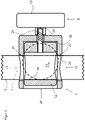
- FIG 1 shows an embodiment of a trampoline according to the invention.
- the trampoline has a frame 1 which is supported by a plurality of legs 2 on the ground.
- the frame holds a jumping sheet 3 which is held on the frame by a large number of spring elements 4 .
- the spring elements 4 can be rubber cable sections that are either open or closed. Both variants are known from the prior art.
- the bungee cord sections can be hooked into receiving elements, for example hook elements, fastened to the jumping mat.
- metal springs are used, which are also known from the prior art.
- a rod 5 is attached to the trampoline.
- the rod 5 is designed as a holding rod and has a handle 6 .
- the rod can also have a holder for an electronic device such as a tablet PC or the like.
- the rod can also take on other tasks.
- a rubber-elastic band can be attached to the bar to support exercises on the trampoline to be attached.
- the support rod 5 is held in a guide 7 which is attached to the frame 1, for example screwed or welded.
- the guide can also be attached to one of the legs 2.
- the support rod 5 is height-adjustable and by means of a (in figure 1 only indicated) actuating device 8 in the guide 7 can be fixed.
- figure 2 shows the guide 7 from figure 1 closer in detail.
- the guide 7 is welded to the frame 1, as can be seen by the weld 9.
- the frame 1 is separated where the guide 7 is inserted and forms a recess A.
- the recess is in figure 6 shown.
- the actuating device 8 has a handle 10 which can be made of plastic.
- the handle sits on an axis of rotation 11, which has a thread, as in connection with Figures 3 and 4 will be described in more detail.
- FIG 3 shows a section through the guide 7 in a schematic representation.
- the guide 7 is welded to the frame 1.
- the frame 1 preferably includes the guide on both sides.
- the frame is in figure 3 indicated with a dashed line.
- the support rod 5 is slidably received in the direction of its longitudinal axis.
- the support bar 5 is in the guide 7 can be fixed.
- an inner piece 12 is movably accommodated in the guide 7 .
- the inner piece 12 is preferably guided in the guide 7 in a displaceable manner.
- the core 12 is substantially cylindrical.
- the guide 7 has two openings 13 which are preferably aligned.
- the inner piece 12 also has an opening 14 .
- the rod 5 can be pushed through the openings 13,14.
- the openings 13, 14 are appropriately aligned and are preferably designed to be larger than the cross section of the rod 5, so that the rod can be inserted through the openings.
- the support rod can have a round cross-section. Alternatively, it has an angular, in particular square, cross section.
- the openings are adapted to the cross-sectional shape of the support rod.
- the inner piece 12 is coupled to the actuating device 8 .
- the inner piece 7 has an internal thread 15 which engages with a threaded pin 16 of the actuating device 8 .
- the threaded stem 16 is rotated by means of the handle 10. Due to the threaded engagement between the inner piece 12 and the actuating device 8, a rotation of the handle 10 leads to a movement of the inner piece 12 in the guide 7.
- the actuating device 8 is supported on the guide 7 here.
- the guide 7 preferably has an end wall 17 on which the actuating device 8 is supported.
- the inner piece 12 is shown in an open position.
- the support rod 15 is movable in the guide. That is, the openings 13 and 14 are aligned so that they leave enough play for the support rod 5 to be moved.
- the cross section of the opening 14 of the inner piece 12 is larger than the cross section of the openings 13 of the guide.
- figure 4 shows the support rod 5 in a fixed state.
- the retaining rod 5 is clamped by turning the handle 10 of the actuator 8 so that the thread 16 pulls the inner piece 12 towards the handle 10, as indicated by the arrow P1.
- the construction can in principle also be such that by actuating the actuating device 8 the inner piece 12 is moved in the other direction, ie counter to the arrow P1, and the holding rod 5 is thus fixed.
- the actuating device 8 must then be supported on the inside 18 of the guide in order to apply the force to the inner piece 12.
- a locking ring can be provided for this purpose, for example.
- the opening 14 also moves in the direction of the arrow P1 until the inside 19 of the inner piece 12 comes to rest against the retaining rod 5.
- the retaining rod 5 is pressed against the inside 20 of the opening 13 of the guide 7 and thereby fixed.
- the holding rod 5 is clamped with a large holding surface provided by the inside 19 .
- the Guide two contact surfaces 21, 22 is available.
- one contact surface 21 is arranged at the top and one contact surface 22 is arranged at the bottom.
- one contact surface 22 can be arranged above the frame and the other contact surface 22 can be arranged below the frame.
- Such an embodiment of the invention creates an advantageous alignment of the support rod 5 with respect to the frame 1.
- figure 5 shows an alternative embodiment to the Figures 3 and 4 .
- the embodiment after figure 5 shows the support rod in a fixed state.
- the embodiment differs from the Figures 3 and 4 in that the actuating device 8 does not have a threaded pin but a nut 23 .
- the inner piece 12 has a threaded pin 24 .
- the inner piece 7 and the actuating device 8 are in threaded engagement.
- the figures 6 and 7 show the interaction of the inner piece 12 and the guide 7.
- the actuating device and the holding rod are omitted from the illustration.
- the inner piece 12 and the guide 7 are in a position in which the openings 13 (of the guide) and 14 (of the inner piece) are aligned. In this position, the support bar can be used.
- the resulting from the superimposition of the openings 13, 14 cut opening must be at least as large as the cross section of Holding rod, so that the holding rod can be pushed through the guide 7 and the inner piece 12.
- figure 7 shows a position of the inner piece 12 in a slightly pulled out of the guide 7 position. It is clear here that it is advantageous if the guide has an opening 25 located radially on the inside. The opening 25 is preferably located opposite the end wall 17 . Through this opening 25, the inner piece 12 can be inserted into the guide 7 for assembly and pulled out for disassembly. So assembly is very easy. At the same time, the combination of the inner piece 12 and the guide 7 creates a stable clamping of the holding rod via the inner sides 19 and 20, as explained above.
- the guide 7 is advantageously designed as a piece of pipe. Such a piece of pipe is easy to produce and stable.
- the pipe piece can have an end wall 17 on one side, through which the actuating device or a threaded pin extending from the inner piece 12 (see figure 5 ) passes through.
- FIG 8 shows an alternative embodiment of the actuating device 8 .
- the actuating device has a clamping lever 26 .
- the clamping lever and the inner piece are preferably in threaded engagement with one another (analogous to the Figures 3 to 5 ). Rough adjustment is possible via the thread.
- the final clamping force is applied via the clamping lever, which is advantageously supported on an intermediate piece 27 or directly on the guide 7. The intermediate piece 27 rests against the guide 7 .
- the frame shape is shown in the figures only around. It can also be polygonal, in particular hexagonal or octagonal.
- indefinite location information such as “above”, “below” or “to the side” is related to a stationary trampoline.
- Location information or direction information such as radially inside or radially outside is also used.
- the frame which can be either round or square (in plan view). If it is round, the round frame forms a center of curvature. The information relates to this point.
- a guide that extends radially lies on a line that extends radially outward from the center of curvature.
- straight frame sections are regularly provided between the corners. The guide will be placed in the middle of the frame sections.
- each frame section intersects at the center of the frame so that, for example, a length of tubing extending radially toward the angular frame lies on a line going radially outward from the center. In the middle of the frame section, this line intersects the frame perpendicularly.
Landscapes
- Engineering & Computer Science (AREA)
- General Engineering & Computer Science (AREA)
- Mechanical Engineering (AREA)
- Health & Medical Sciences (AREA)
- General Health & Medical Sciences (AREA)
- Physical Education & Sports Medicine (AREA)
- Life Sciences & Earth Sciences (AREA)
- Biophysics (AREA)
- Orthopedic Medicine & Surgery (AREA)
- Mutual Connection Of Rods And Tubes (AREA)
- Clamps And Clips (AREA)
- Prostheses (AREA)
Description
- Die Erfindung betrifft ein Trampolin mit den Merkmalen des Patentanspruchs 1. Die Erfindung ist insbesondere gerichtet auf so genannte Mini-Trampoline, die auch Fitness-Trampoline genannt werden. Hierbei handelt es sich um kleinere Trampoline mit einem maximalen Durchmesser von 2 bis 3 Metern, die in der Physiotherapie und im Fitnessbereich Einsatz finden.
- Bei den so genannten Mini- oder Fitness-Trampolinen unterscheidet man zwischen Trampolinen mit einer Federaufhängung und einer Gummiseilaufhängung. Bei der Federaufhängung ist das Sprungtuch über Spiralfedern an dem Rahmen befestigt. Hierzu weist das Sprungtuch als Aufnahmeeinrichtung beispielsweise einen Bügel bzw. eine Öse auf, die mittels einer Schlaufe an dem Sprungtuch befestigt ist und in die jeweils eine Spiralfeder eingreift. Auf ihrer anderen Seite wird die Spiralfeder in den Rahmen eingehängt. Ein Trampolin mit einer Federaufhängung stellt erhebliche Beschleunigungskräfte zur Verfügung.
- Bei der Gummiseilaufhängung kommen ein oder mehrere elastische Seilringe oder (offene) Seile zum Einsatz, die das Sprungtuch mit dem Rahmen verbinden. Hier kann die Aufnahmeeinrichtung als Hakenelement ausgebildet sein, in das jeweils eine Aufhängung eingehängt ist. Alternativ kommt auch eine Schlaufe in Betracht, durch die hindurch ein Seil gezogen ist, das das Sprungtuch mit dem Rahmen verbindet. Die größere Elastizität einer derartigen Gummiseilaufhängung sorgt für ein "weicheres" Abbremsen des Körpers und schont insoweit nicht nur die Gelenke, sondern verlängert auch die muskulären Belastungs- und Entlastungsphasen beim Springen, was vorteilhafte Trainingseffekte mit sich bringt.
- Die Erfindung ist sowohl auf Trampoline mit Federaufhängungen als auch auf Trampoline gerichtet, bei denen die Aufhängung als elastisches Seil oder elastischer Seilring ausgebildet ist. Grundsätzlich kann die Erfindung bei jeglicher Art von Trampolinen Einsatz finden, unabhängig von der Art der Aufhängung des Sprungtuchs und der Geometrie des Rahmens.
- Den bekannten Trampolinen ist gemein, dass sie über einen Rahmen verfügen, von dem Beine abgehen. Die Beine sorgen dafür, dass sich der Rahmen in einem bestimmten Abstand zum Boden befindet, wenn das Trampolin aufgestellt ist. Hierdurch wird gewährleistet, dass sich das Sprungtuch beim Springen in Richtung auf den Boden bewegen kann.
- Aus der Praxis sind sowohl runde als auch polygonale Rahmenformen bekannt. Der Rahmen besteht aus einem Rohr, das zur Herstellung des Rahmens gebogen wird.
- In jüngerer Zeit ist ein Fitnesstrend zu beobachten, bei dem spezielle Bewegungsprogramme auf das Trampolin abgestimmt werden. Für einen sicheren Halt auf dem Trampolin kommt die Haltestange zum Einsatz, wobei die Haltestange in aller Regel an ihrem freien Ende seitlich von der Haltestange abgehende Griffe aufweist, an denen sich der Benutzer während der Übungen festhalten kann.
- Aus der
DE 20 2014 007 636 U1 ist ein Trampolin bekannt, bei dem die Haltestange über ein Zwischenstück an einem Bein des Trampolins befestigt ist. Zusätzlich ist die Haltestange durch zwei seitliche Streben gesichert, die das untere Ende der Haltestange mit den benachbarten Beinen des Trampolins verbinden. Die bekannte Konstruktion ist stabil. Sie bedingt jedoch einen hohen Materialaufwand. Außerdem ist der Zusammenbau aufwendig. - Aus der
US 2007/0012902 A1 ist ein Trampolin mit einer Haltestange bekannt, die zum Halten eines Sicherheitsnetzes dient. Die Haltestange ist durch eine Führung höhenverstellbar an jeweils einem Bein des Trampolins gehalten, wobei die Führung sowohl das jeweilige Bein als auch die Haltestange umklammert und fixiert. - Aus der
US 8,657,129 B2 ist ein Rack mit einem Gestell bekannt, an dem Musikinstrumente wie zum Beispiel ein Becken mit einer Stange befestigt werden kann. Die Stange ist in einer Führung aufgenommen, die an dem Gestell befestigt ist. - Aus der Praxis ist ein Trampolin bekannt, an dessen Rahmen eine Klemmvorrichtung angeschweißt ist. Die Haltestange ist in der Klemmvorrichtung längsverschieblich aufgenommen und arretierbar. Das bekannte Trampolin ist einfach aufgebaut und zusammensetzbar. In der Praxis wurde allerdings gefunden, dass die Lebensdauer zu wünschen übrig lässt.
- Der Erfindung liegt die Aufgabe zugrunde, ein Trampolin mit Stange zu schaffen, dessen Aufbau einerseits kompakt ist und das andererseits auch höheren Belastungen standhält.
- Diese Aufgabe wird erfindungsgemäß gelöst durch ein Trampolin mit den Merkmalen des Patentanspruchs 1.
- Die Erfindung gestattet eine Fixierung der Stange in der Führung, die auch höheren Belastungen während einer intensiven Benutzung des Trampolins standhält. Dabei stellt das Innenstück die Klemmkraft zur Verfügung. Vorzugsweise wird die Stange zwischen der Führung und dem Innenstück verklemmt.
- Der Führung kommen im Rahmen der Erfindung zwei Aufgaben zu. Erstens nimmt sie die Stange auf und fixiert sie. Zweitens bildet sie vorteilhaft eine Aufnahme für das Innenstück.
- Im Rahmen der Erfindung kann eine Stange zum Einsatz kommen, die ein freies Ende aufweist. Das freie Ende trägt beispielsweise eine Griffeinrichtung oder eine Halterung für Geräte. Dann wird man für die Stange lediglich eine Führung vorsehen. Alternativ kann eine Stange zum Einsatz kommen, die U-förmig gebogen ist. Sie weist zwei freie Enden auf, von denen jeweils ein Ende in eine Führung gesteckt werden kann. Dann wird man vorzugsweise zwei Führungen für die Stange vorsehen. In der folgenden Beschreibung wird aus Übersichtsgründen ein Gestell mit lediglich einer Führung beschrieben.
- Vorteilhafterweise weist die Führung mindestens eine erste Öffnung auf, durch die hindurch die Stange gesteckt ist. Die Öffnung ist zweckmäßig an die Außenkontur der Stange angepasst, jedoch größer ausgebildet als die Außenkontur des Stange, damit die Stange problemlos in die Führung eingesteckt und in ihrer Höhe verstellt werden kann. Bevorzugt sind zwei Öffnungen in der Führung vorgesehen. Dies führt zu einer stabileren Führung der Stange. Die beiden Öffnungen sind (bei aufgestelltem Trampolin) oben und unten in der Führung ausgebildet. Sie fluchten zweckmäßig.
- In Weiterbildung der Erfindung wird vorgeschlagen, dass die Führung als Rohrstück ausgebildet ist. Vorzugsweise weist die Führung eine umlaufende Umfangswandung auf. Das Rohrstück ist eine besonders stabile und gleichzeitig einfach herzustellende Ausführungsform der Führung. Der Querschnitt des Rohrstücks kann rund oder eckig, insbesondere kreisrund oder quadratisch ausgebildet sein. Auch kommen ovale oder rechteckige Querschnittsflächen in Betracht. Im Rahmen der Erfindung wird der kreisrunde Querschnitt als besonders vorteilhaft angesehen, und zwar zum einen aus herstellungstechnischen Gründen und zum anderen aus sicherheitstechnischen Gründen, da die runde Form bei der vorliegenden Anwendung ein geringeres Verletzungsrisiko birgt.
- Die erste Öffnung ist vorzugsweise in der Umfangswandung ausgebildet. Sofern das Rohrstück senkrecht zu der axialen Erstreckung der Beine, also bei einem stehenden Trampolin horizontal angeordnet ist, ist die Öffnung oben angeordnet, wobei es wie gesagt vorteilhaft ist, wenn eine weitere Öffnung auf der Unterseite des Rohrstücks ausgebildet ist. Die Stange geht dann durch die obere und die untere Öffnung der Führung/des Rohrstücks. Die obere und die untere Öffnung fluchten vorzugsweise.
- Es wurde bereits vorstehend ausgeführt, dass das Innenstück in der Führung beweglich angeordnet ist. Vorzugsweise ist die Außenkontur des Innenstücks an die Innenkontur der Führung angepasst. Bei einem Rohrstück mit einer zylindrischen Innenfläche ist es also vorteilhaft, wenn das Innenstück eine zylindrische Außenfläche aufweist. Die Außenfläche hat einen geringfügig kleineren Durchmesser als der Innendurchmesser der Führung, damit das Innenstück in der Führung gut beweglich ist, was eine Fixierung der Stange in der Führung vereinfacht.
- Als vorteilhaft wird es angesehen, wenn das Innenstück eine Öffnung aufweist, durch die die Stange hindurchgeht. Die Öffnung kann gebohrt sein. Sie geht im Falle eines Zylinderstücks quer durch das Zylinderstück.
- Vorzugsweise kann das Innenstück in der Führung so ausgerichtet werden, dass die Öffnungen der Führung und die Öffnung des Innenstücks fluchten. Die Öffnungen des Innenstücks und der Führung müssen nicht zwangsweise gleich groß sein. Allerdings sind sie mindestens so groß wie der Außendurchmesser der Stange.
- In diesem Zusammenhang sei angemerkt, dass vorstehend von der Ausführungsform eines zylindrischen Innenstücks gesprochen worden ist. Die Öffnung für die Stange durchbricht die Zylinderform. Gleichwohl handelt es sich im Sinne der Erfindung um eine Zylinderform (mit einer Öffnung).
- Neben einer hohen Anforderung an die Stabilität des Trampolins wird auch gefordert, dass aus Benutzersicht der Zusammenbau, die Befestigung der Stange an dem Trampolin und ggf. die Wartung einfach möglich ist. In diesem Zusammenhang wird vorgeschlagen, dass die Führung eine dritte Öffnung aufweist, durch die hindurch das Innenstück in die Führung einsteckbar ist. Bei einem Rohrstück wird man die Einstecköffnung an der Stirnseite vorsehen. Ein bevorzugtes Ausführungsbeispiel ist dadurch gekennzeichnet, dass die Einsteckrichtung senkrecht zu den beiden Öffnungen in der Umfangsfläche der Führung verläuft. Als bevorzugt wird es ebenfalls angesehen, wenn die Einstecköffnung radial innen angeordnet ist. Das Innenstück wird vorteilhaft von innen nach außen in die Führung eingesteckt.
- Vorzugsweise entspricht der Durchmesser der Öffnung dem Innendurchmesser der Führung. Das Innenstück kann also einfach in die Führung eingeschoben werden. Dort ist das Innenstück vorteilhaft verschieblich aufgenommen.
- Zum Bewegen des Innenstücks ist vorteilhaft eine Betätigungseinrichtung vorgesehen. Vorzugsweise wird das Innenstück von einer Betätigungseinrichtung betätigt. Die Erfindung schafft damit eine Klemmeinrichtung für die Stange, die lediglich aus drei Grundkomponenten besteht und gegenüber herkömmlichen Lösungen eine deutlich bessere und stabilere Klemmung zur Verfügung stellt. Die Klemmeinrichtung wird gebildet aus Führung, Innenstück und Betätigungseinrichtung.
- Eine besonders vorteilhafte Ausführungsform der Erfindung ist dadurch gekennzeichnet, dass sich die Betätigungseinrichtung an dem Rahmen oder vorzugsweise an der Führung abstützt. Eine derartige Konstruktion schafft eine kompakte Gesamtkonstruktion, die gleichzeitig in der Lage ist, große Klemmkräfte auf die Stange aufzubringen. Vorzugsweise weist die Führung eine Stirnwand auf, an der sich die Betätigungseinrichtung abstützt.
- Zur Aufbringung der Klemmkräfte wird vorgeschlagen, dass die Betätigungseinrichtung und das Innenstück in Gewindeeingriff stehen. Durch ein Drehen der Betätigungseinrichtung wird das Innenstück in der Führung bewegt. Dabei wird die Stange vorteilhaft zwischen der Führung und dem Innenstück fixiert, wie es grundsätzlich als vorteilhaft angesehen wird.
- Beim Drehen der Betätigungseinrichtung sind generell zwei Bewegungsmodelle denkbar. Entweder das Innenstück bewegt sich von der Betätigungseinrichtung weg, wenn die Betätigungseinrichtung gedreht wird, oder sie bewegt sich zur Betätigungseinrichtung hin.
- Der Gewindeeingriff kann dadurch realisiert werden, dass die Betätigungseinrichtung einen Gewindezapfen aufweist, der in ein Gewinde des Innenstücks eingreift. Bei der Betätigungseinrichtung handelt es sich beispielsweise um eine Handschraube, die einen Handgriff beispielsweise aus Kunststoff und den besagten Gewindezapfen aufweist. Das Gewinde ist vorzugsweise stirnseitig in dem Innenstück ausgebildet.
- Alternativ weist das Innenstück einen Gewindezapfen auf, der in ein Gewinde der Betätigungseinrichtung eingreift. Die Betätigungseinrichtung kann auch hier einen Handgriff (beispielsweise auf Kunststoff) aufweisen, wobei in dem Handgriff eine Mutter aufgenommen ist.
- Bei den beiden vorstehend beschriebenen Ausführungsformen weist die Betätigungseinrichtung Handgriffe auf, die zum Herbeiführen der Bewegung des Innenstücks gedreht werden. Alternativ ist die Betätigungseinrichtung als Spannhebel ausgebildet, dessen Schwenken ein Bewegen des Innenstücks in Richtung auf den Hebel bewirkt. Der Spannhebel kann analog zu dem Handgriff ein Gewinde oder einen Gewindezapfen aufweisen, das bzw. der mit dem Innenstück zusammenwirkt. Über das Gewinde wird eine Voreinstellung vorgenommen. Zum Aufbringen der finalen Klemmkraft wird der Spannhebel geschwenkt. Die Mechanik von Spannhebeln ist als solche bekannt. Die Spannung erfolgt über einen Exzenter des Spannhebels.
- Das erfindungsgemäße Trampolin kann in Privathaushalten, aber insbesondere auch in Fitnessstudios zum Einsatz kommen. In Fitnessstudios werden die erfindungsgemäßen Trampoline häufig in Gruppen eingesetzt. Dies bedeutet, dass die Trampoline nach ihrer Benutzung verstaut werden müssen. In diesem Zusammenhang wird vorgeschlagen, dass die Betätigungseinrichtung einen Hebel aufweist, mit dem die Betätigungseinrichtung drehbar ist, wobei der Hebel in der Betätigungseinrichtung längsverschieblich gelagert ist. Der Hebel erleichtert durch seine Verschiebbarkeit die Stapelbarkeit der Trampoline. Beim Stapeln wird man den Hebel in eine solche Stellung bringen, in der er für das benachbarte (aufgesetzte) Trampolin kein Hindernis ist. Der Hebel kann aus Metall hergestellt sein. Ein weiterer Vorteil des Hebels besteht darin, dass das Anzugsmoment relativ groß ist, was zu einer großen Klemmkraft führt.
- Die Führung kann auf verschiedenen Weise mit dem Gestell verbunden sein. Beispielsweise kann die Führung mit dem Rahmen oder einem Bein verschraubt oder verklebt sein. Häufig sind die Gestelle aus Metall, insbesondere aus Stahl oder Edelstahl hergestellt. In diesem Zusammenhang wird vorgeschlagen, dass die Führung mit dem Gestell verschweißt ist. Eine derartige Befestigung ist besonders gut in der Lage, die bei der Benutzung des Trampolins auftretenden periodischen Belastungen aufzunehmen.
- An dieser Stelle sei darauf hingewiesen, dass der Stange mehrere Funktionen zukommen können. Wie bereits eingangs angedeutet, kann die Stange als Haltestange ausgebildet sein und mindestens eine Griffeinrichtung aufweisen, an der sich der Benutzer während des Springens oder Schwingens festhalten kann. Die Griffeinrichtung umfasst beispielsweise zwei seitlich von der Stange abgehende Griffe. Alternativ oder zusätzlich ist es möglich, dass die Stange (ggf. zusätzlich) eine Aufnahme für ein elektronisches Gerät aufweist. Hierbei kann es sich um ein Tablet-PC oder beispielsweise ein Gerät handeln, das die Körperfunktionen des Benutzers misst und/oder überwacht.
- Bei der Verwendung der Stange als Haltestange wirken auf die Haltestange während der Benutzung erhebliche Kräfte. Damit ist die Führung einer besonderen Belastung ausgesetzt, insbesondere vor dem Hintergrund, dass auf die Führung aufgrund der Längserstreckung der Haltestange erhebliche Hebelkräfte wirken. Erfindungsgemäß wird vorgeschlagen, dass der Rahmen eine Aussparung bildet, in der die Führung aufgenommen ist. Bei der Aussparung kann es sich um eine teilweise Aussparung handeln, bei der der Rahmen nicht vollständig geöffnet (im Sinne von durchgetrennt) ist, sondern lediglich eine Vertiefung in dem Rahmen ausgebildet ist. Gegenüber herkömmlichen Lösungen, bei denen die Stange oder ihre Aufnahme lediglich seitlich an den Rahmen angeschweißt ist, bildet die Aussparung eine größere Kontaktfläche, was eine wesentliche Steigerung der Festigkeit zur Folge hat. Die durch die Aussparung zunächst in Kauf genommene Schwächung des Rahmens wird also durch das Anbringen der Führung kompensiert mit dem erheblichen Vorteil einer stabilen Befestigung der Führung und damit einer langlebigen und stabilen Gesamtkonstruktion, die auch den hohen Hebelkräften beim Training auf dem Trampolin standhält.
- Als besonders vorteilhaft wird es angesehen, wenn der umlaufende Rahmen durchbrochen ist und die Führung in die sich ergebende Aussparung eingesetzt ist. Bei Metallrahmen ist die Führung zweckmäßig eingeschweißt. Der Rahmen liegt also vorteilhaft beidseitig an der Führung an. Hierdurch kann eine große Kontaktfläche erreicht werden. Dadurch wird die Führung exzellent gehalten. Gleichzeitig bleibt der Rahmen stabil. Der Einsatz der Führung in den Rahmen weist den weiteren Vorteil einer kompakten Bauweise auf. Hierdurch ist das Trampolin gut stapelbar.
- Bereits vorstehend wurde erwähnt, dass es vorteilhaft ist, wenn die Führung als Rohrstück ausgebildet ist. Hierbei kann es sich um ein eckige oder ein rundes (zylindrisches) Rohrstück handeln. Die Herstellung eines Rohrstücks ist günstig. Eine runde Form reduziert das Verletzungsrisiko.
- Eine vorteilhafte Ausführungsform der Erfindung ist dadurch gekennzeichnet, dass das Rohrstück senkrecht zu der Erstreckungsrichtung der Beine angeordnet ist. Insbesondere wird vorgeschlagen, dass sich das Rohrstück radial nach innen in Bezug auf den umlaufenden Rahmen öffnet. Diese Ausführungsform baut sehr kompakt. Das Innenstück kann radial von innen in das Rohrstück eingesteckt werden. Seine Bewegungsrichtung ist vorzugsweise radial. Ein Rohrstück begünstigt ferner die Stapelbarkeit. Die Erfindung gestattet es, dass das Rohrstück nach oben und unten maximal 2 cm über den Rahmen übersteht, wie es grundsätzlich im Rahmen der Erfindung als vorteilhaft angesehen wird.
- Vorzugsweise weist die Führung eine Stirnwand auf. An der Stirnwand stützt sich vorteilhaft die Betätigungseinrichtung ab. Die Stärke der Stirnwand wird man so wählen, dass sie die Klemmkräfte, die die Betätigungseinrichtung auf sie ausübt, aufnehmen kann. Vorzugsweise greift die Betätigungseinrichtung durch die Stirnwand hindurch. Die Betätigungseinrichtung ist zweckmäßig drehbar in der Stirnwand gelagert.
- Im Folgenden wird die Erfindung anhand eines bevorzugten Ausführungsbeispiels im Zusammenhang mit der anhängenden Zeichnung näher erläutert. Die Zeichnung zeigt in:
- Figur 1:
- in schematischer Darstellung eine perspektivische Ansicht eines erfindungsgemäßen Trampolins mit Haltestange;
- Figur 2:
- in schematischer Darstellung die Befestigung der Haltestange an dem Trampolinrahmen;
- Figur 3:
- in schematischer Darstellung eine Schnittansicht durch die Führung, in der die Haltestange lösbar aufgenommen ist;
- Figur 4:
- in schematischer Darstellung die Schnittansicht nach
Figur 3 , wobei die Haltestange in der Führung fixiert ist; - Figur 5:
- in schematischer Darstellung ein alternatives Ausführungsbeispiel zu den
Figuren 3 und4 ; - Figur 6:
- in schematischer Darstellung das Zusammenwirken zwischen dem Innenstück und der Führung, wobei das Innenstück in der Führung aufgenommen ist;
- Figur 7:
- in schematischer Darstellung die Führung und das Innenstück nach
Figur 7 , wobei das Innenstück leicht aus der Führung herausgezogen ist; und - Figur 8:
- in schematischer Darstellung eine alternative Ausführungsform der Betätigungseinrichtung.
-
Figur 1 zeigt ein Ausführungsbeispiel eines erfindungsgemäßen Trampolins. Das Trampolin weist einen Rahmen 1 auf, der sich mit einer Mehrzahl von Beinen 2 am Boden abstützt. Der Rahmen hält ein Sprungtuch 3, das über eine Vielzahl von Federelementen 4 an dem Rahmen gehalten ist. Bei den Federelementen 4 kann es sich um Gummiseilabschnitte handeln, die entweder offen oder geschlossen ausgebildet sind. Beide Varianten sind aus dem Stand der Technik bekannt. Die Gummiseilabschnitte können in an dem Sprungtuch befestigte Aufnahmeelemente, zum Beispiel Hakenelemente, eingehängt sein. Alternativ kommen Metallfedern zum Einsatz, welche ebenfalls aus dem Stand der Technik bekannt sind. - An dem Trampolin ist eine Stange 5 befestigt. Die Stange 5 ist bei dem dargestellten Ausführungsbeispiel als Haltestange ausgebildet und weist einen Griff 6 auf. Alternativ oder zusätzlich kann die Stange auch eine Halterung für ein elektronisches Gerät wie zum Beispiel ein Tablet-PC oder dergleichen aufweisen. Die Stange kann auch andere Aufgaben übernehmen. Beispielsweise kann an der Stange ein gummielastisches Band zur Unterstützung bei Übungen auf dem Trampolin befestigt werden. Der Einfachheit halber wird im Folgenden ausschließlich Bezug genommen auf eine Haltestange.
- Die Haltestange 5 ist in einer Führung 7 gehalten, die am Rahmen 1 befestigt, beispielsweise geschraubt oder geschweißt ist. Die Führung kann auch an einem der Beine 2 befestigt sein. Die Haltestange 5 ist höhenverstellbar und mittels einer (in
Figur 1 lediglich angedeuteten) Betätigungseinrichtung 8 in der Führung 7 fixierbar. -
Figur 2 zeigt die Führung 7 ausFigur 1 genauer im Detail. Die Führung 7 ist an dem Rahmen 1 festgeschweißt, wie dies durch die Schweißnaht 9 ersichtlich ist. Hierzu ist der Rahmen 1 dort, wo die Führung 7 eingesetzt wird, aufgetrennt und bildet eine Aussparung A. Dies verleiht der Gesamtkonstruktion eine hohe Stabilität bei gleichzeitig elegantem und schlankem Design. Die Aussparung ist aus Übersichtsgründen inFigur 6 dargestellt. - Die Betätigungseinrichtung 8 weist einen Handgriff 10 auf, der aus Kunststoff ausgebildet sein kann. Der Handgriff sitzt auf einer Drehachse 11, die in ein Gewinde aufweist, wie es im Zusammenhang mit den
Figuren 3 und4 noch näher beschrieben wird. - Es wird auf
Figur 3 Bezug genommen, die in schematischer Darstellung einen Schnitt durch die Führung 7 zeigt. Die Führung 7 ist mit dem Rahmen 1 verschweißt. Der Rahmen 1 umfasst die Führung vorzugsweise beidseitig. Der Rahmen ist inFigur 3 mit einer Strichlinie angedeutet. - In der Führung 7 ist die Haltestange 5 in Richtung ihrer Längsachse verschiebbar aufgenommen. Die Haltestange 5 ist in der Führung 7 fixierbar. Hierzu ist in der Führung 7 ein Innenstück 12 bewegbar aufgenommen. Das Innenstück 12 ist vorzugsweise in der Führung 7 verschiebbar geführt. Vorzugsweise ist das Innenstück 12 im Wesentlichen zylindrisch.
- Die Führung 7 weist zwei Öffnungen 13 auf, die vorzugsweise fluchten. Das Innenstück 12 weist ebenfalls eine Öffnung 14 auf. Die Stange 5 ist durch die Öffnungen 13, 14 hindurchsteckbar. Die Öffnungen 13, 14 fluchten hierzu zweckmäßig und sind vorzugsweise größer ausgebildet als der Querschnitt der Stange 5, damit die Stange durch die Öffnungen hindurchgesteckt werden kann.
- An dieser Stelle sei darauf hingewiesen, dass in
Figur 3 lediglich ein Teil der Haltestange dargestellt ist. Die Haltestange kann einen runden Querschnitt aufweisen. Alternativ weist sie einen eckigen, insbesondere quadratischen Querschnitt auf. Die Öffnungen sind an die Querschnittsform der Haltestange angepasst. - Das Innenstück 12 ist mit der Betätigungseinrichtung 8 gekoppelt. Hierzu weist das Innenstück 7 ein Innengewinde 15 auf, das mit einem Gewindezapfen 16 der Betätigungseinrichtung 8 in Eingriff steht. Der Gewindezapfen 16 wird mittels des Handgriffs 10 gedreht. Aufgrund des Gewindeeingriffs zwischen dem Innenstück 12 und der Betätigungseinrichtung 8 führt eine Drehung des Handgriffs 10 zu einer Bewegung des Innenstücks 12 in der Führung 7. Hierbei stützt sich die Betätigungseinrichtung 8 an der Führung 7 ab. Vorzugsweise weist die Führung 7 eine Stirnwand 17 auf, an der sich die Betätigungseinrichtung 8 abstützt.
- In
Figur 3 ist das Innenstück 12 in einer Öffnungsstellung gezeigt. In dieser ist die Haltestange 15 in der Führung bewegbar. Das heißt, die Öffnungen 13 und 14 sind so ausgerichtet, dass sie der Haltestange 5 genug Spiel lassen, um bewegt zu werden. Vorzugsweise ist Querschnitt der Öffnung 14 des Innenstücks 12 größer als der Querschnitt der Öffnungen 13 der Führung. -
Figur 4 zeigt die Haltestange 5 in einem fixierten Zustand. Die Haltestange 5 wird dadurch eingeklemmt, dass der Handgriff 10 der Betätigungseinrichtung 8 so gedreht wird, dass das Gewinde 16 das Innenstück 12 in Richtung auf den Handgriff 10 heranzieht, wie dies durch den Pfeil P1 angedeutet ist. Es sei angemerkt, dass die Konstruktion grundsätzlich auch so beschaffen sein kann, dass durch Betätigen der Betätigungseinrichtung 8 das Innenstück 12 in die andere Richtung, also entgegen des Pfeils Pl, bewegt wird und damit die Haltestange 5 fixiert. Dann muss sich die Betätigungseinrichtung 8 auf der Innenseite 18 der Führung abstützen, um die Kraft auf das Innenstück 12 aufzubringen. Hierzu kann beispielsweise ein Sperrring vorgesehen sein. - Beim Bewegen des Innenstücks 12 in Richtung des Pfeils P1 wandert die Öffnung 14 ebenfalls in Richtung des Pfeils Pl, bis die Innenseite 19 des Innenstücks 12 zur Anlage an die Haltestange 5 gelangt. Die Haltestange 5 wird gegen die Innenseite 20 der Öffnung 13 der Führung 7 gepresst und dadurch fixiert. Als vorteilhaft bei diesem Ausführungsbeispiel wird es angesehen, dass die Haltestange 5 mit einer großen Haltefläche, die von der Innenseite 19 zur Verfügung gestellt wird, verklemmt wird. Dies schafft eine stabile und dauerhafte Fixierung der Haltestange in der Führung 7. Als vorteilhaft wird es ferner angesehen, dass die Führung zwei Anlageflächen 21, 22 zur Verfügung stellt. Vorzugsweise ist die eine Anlagefläche 21 oben und eine Anlagefläche 22 unten angeordnet. Insbesondere kann die eine Anlagefläche 22 oberhalb des Rahmens und die andere Anlagefläche 22 unterhalb des Rahmens angeordnet sein. Eine derartige Ausführung der Erfindung schafft eine vorteilhafte Ausrichtung der Haltestange 5 gegenüber dem Rahmen 1.
-
Figur 5 zeigt ein alternatives Ausführungsbeispiel zu denFiguren 3 und4 . Aus Übersichtsgründen werden dieselben oder ähnliche Bauteile mit denselben Bezugsziffern gekennzeichnet, auch wenn sie baulich geringfügig voneinander abweichen sollten. Das Ausführungsbeispiel nachFigur 5 zeigt die Haltestange in einem fixierten Zustand. Das Ausführungsbeispiel unterscheidet sich von denFiguren 3 und4 dadurch, dass die Betätigungseinrichtung 8 keinen Gewindezapfen aufweist, sondern eine Mutter 23. Das Innenstück 12 weist einen Gewindezapfen 24 auf. Das Innenstück 7 und die Betätigungseinrichtung 8 stehen in Gewindeeingriff. Durch Drehen des Handgriffs wird - wie bei dem Ausführungsbeispiel gemäß derFiguren 3 und4 - das Innenstück 12 in Richtung des Pfeils P1 gezogen. - Die
Figuren 6 und7 zeigen das Zusammenwirken des Innenstücks 12 und der Führung 7. Aus Übersichtsgründen sind die Betätigungseinrichtung und die Haltestange in der Darstellung weggelassen. InFigur 6 befinden sich das Innenstück 12 und die Führung 7 in einer Stellung, in der die Öffnungen 13 (der Führung) und 14 (des Innenstücks) fluchten. In dieser Stellung kann die Haltestange eingesetzt werden. Die sich aus der Überlagerung der Öffnungen 13, 14 ergebende Schnittöffnung muss mindestens so groß sein wie der Querschnitt der Haltestange, damit die Haltestange durch die Führung 7 und das Innenstück 12 hindurchsteckbar ist. -
Figur 7 zeigt eine Stellung des Innenstücks 12 in einer leicht aus der Führung 7 herausgezogenen Stellung. Hier wird deutlich, dass es vorteilhaft ist, wenn die Führung eine radial innen liegende Öffnung 25 aufweist. Vorzugsweise liegt die Öffnung 25 der Stirnwand 17 gegenüber. Durch diese Öffnung 25 kann das Innenstück 12 für die Montage in die Führung 7 eingesteckt und zur Demontage herausgezogen werden. Die Montage ist also sehr einfach. Gleichzeitig schafft die Kombination aus Innenstück 12 und Führung 7 über die Innenseiten 19 und 20 eine stabile Verklemmung der Haltestange, wie vorstehend ausgeführt. - Die Führung 7 ist vorteilhafterweise als Rohrstück ausgebildet. Ein derartiges Rohrstück ist einfach herstellbar und stabil. Insbesondere kann das Rohrstück einseitig eine Stirnwand 17 aufweisen, durch die die Betätigungseinrichtung oder ein von dem Innenstück 12 abgehender Gewindezapfen (siehe
Figur 5 ) hindurchgeht. -
Figur 8 zeigt eine alternative Ausführungsform der Betätigungseinrichtung 8. Die Betätigungseinrichtung weist einen Spannhebel 26 auf. Auch hier stehen der Spannhebel und das Innenstück vorzugsweise in Gewindeeingriff miteinander (analog denFiguren 3 bis 5 ). Über das Gewinde ist eine Grobeinstellung möglich. Die finale Klemmkraft wird über den Spannhebel aufgebracht, der sich vorteilhafterweise auf einem Zwischenstück 27 oder unmittelbar an der Führung 7 abstützt. Das Zwischenstück 27 liegt an der Führung 7 an. - Die Rahmenform ist in den Figuren ausschließlich rund dargestellt. Sie kann auch polygonal, insbesondere sechs- oder achteckig sein.
- Im Rahmen der Beschreibung werden sämtliche unbestimmte Ortsangaben wie zum Beispiel "über", "unter" oder "seitlich" auf ein stehendes Trampolin bezogen. Es werden ferner Ortsangaben oder Richtungsangaben wie radial innen oder radial außen verwendet. Diese sind bezogen auf den Rahmen, der entweder (in seiner Draufsicht) rund oder eckig ausgebildet sein kann. Sofern er rund ausgebildet ist, bildet der runde Rahmen einen Krümmungsmittelpunkt. Die Angaben sind auf diesen Punkt bezogen. Eine Führung, die sich radial erstreckt, liegt also auf einer Linie, die sich radial von dem Krümmungsmittelpunkt nach außen erstreckt. Bei eckigen Rahmenformen sind regelmäßig zwischen den Ecken gerade Rahmenabschnitte vorgesehen. Die Führung wird man in der Mitte der Rahmenabschnitte anordnen. Die von der Mitte eines jeden Rahmenabschnitts abgehenden Senkrechten schneiden sich im Zentrum des Rahmens, so dass zum Beispiel ein Rohrstück, das sich radial zu dem eckigen Rahmen erstreckt, auf einer Linie liegt, die von dem Zentrum radial nach außen geht. In der Mitte des Rahmenabschnitts schneidet diese Linie den Rahmen senkrecht.
-
- 1
- Rahmen
- 2
- Beine
- 3
- Sprungtuch
- 4
- Federelemente
- 5
- Haltestange
- 6
- Griff
- 7
- Führung
- 8
- Betätigungseinrichtung
- 9
- Schweißnaht
- 10
- Handgriff
- 11
- Drehachse
- 12
- Innenstück
- 13
- Öffnung (der Führung)
- 14
- Öffnung (des Innenstücks)
- 15
- Gewinde
- 16
- Gewindezapfen
- 17
- Stirnfläche
- 18
- Innenseite
- 19
- Innenseite
- 20
- Innenseite (der Öffnung)
- 21
- Anlagefläche
- 22
- Anlagefläche
- 23
- Mutter
- 24
- Gewindezapfen
- 25
- Öffnung
- 26
- Spannhebel
- 27
- Zwischenring
- P1
- Pfeil
- A
- Aussparung
Claims (15)
- Trampolin, mit- einem Gestell, das einen umlaufenden Rahmen (1) und eine Mehrzahl von Beinen (2) aufweist, wobei der Rahmen aus einem Rohr besteht, das zur Herstellung des Rahmens gebogen ist,- einem Sprungtuch (3), das elastisch an dem Rahmen (1) aufgehängt ist,- mindestens einer Führung (7), die an dem Gestell befestigt ist,- einer Stange (5), die höhenverstellbar in der Führung (7) aufgenommen ist, und- einem Innenstück (12), das in der Führung (7) beweglich aufgenommen ist, dadurch gekennzeichnet, dass durch eine Relativbewegung zwischen dem Innenstück (12) und der Führung (7) die Stange (5) fixiert wird, und- dass der Rahmen (1) eine Aussparung (A) bildet, in der die Führung (7) aufgenommen ist.
- Trampolin nach Anspruch 1, dadurch gekennzeichnet, dass die Führung (7) mindestens eine erste Öffnung (13) aufweist, durch die hindurch die Stange (5) gesteckt ist.
- Trampolin nach Anspruch 1 oder 2, dadurch gekennzeichnet, dass die Führung (7) eine umlaufende Umfangswandung aufweist, und dass die erste Öffnung (13) in der Umfangswandung ausgebildet ist.
- Trampolin nach einem der Ansprüche 1 bis 3, dadurch gekennzeichnet, dass das Innenstück (12) eine Öffnung (14) aufweist, durch die die Stange (5) hindurchgeht.
- Trampolin nach einem der Ansprüche 1 bis 4, dadurch gekennzeichnet, dass die Führung eine Öffnung (25) aufweist, durch die hindurch das Innenstück (12) in die Führung (7) einsteckbar ist.
- Trampolin nach Anspruch 5, dadurch gekennzeichnet, dass die Öffnung (25) radial nach innen gerichtet ist.
- Trampolin nach einem der Ansprüche 1 bis 6, dadurch gekennzeichnet, dass das Innenstück (12) mit einer Betätigungseinrichtung (8) gekoppelt ist, die sich an dem Rahmen (1) oder vorzugsweise an der Führung (7) oder an einem der Führung anliegenden Zwischenstück (26) abstützt.
- Trampolin nach Anspruch 7, dadurch gekennzeichnet, dass die Betätigungseinrichtung (8) und das Innenstück (12) in Gewindeeingriff stehen.
- Trampolin nach Anspruch 7 oder 8, dadurch gekennzeichnet, dass die Betätigungseinrichtung (8) einen Gewindezapfen (16) aufweist, der in ein Innengewinde (15) des Innenstücks (12) eingreift.
- Trampolin nach Anspruch 7 oder 8, dadurch gekennzeichnet, dass das Innenstück (12) einen Gewindezapfen (24) aufweist, der in ein Innengewinde (23) der Betätigungseinrichtung (8) eingreift.
- Trampolin nach einem der Ansprüche 6 bis 9, dadurch gekennzeichnet, dass die Betätigungseinrichtung (8) als Spannhebel (25) ausgebildet ist, dessen Schwenken ein Bewegen des Innenstücks (12) in Richtung auf den Spannhebel bewirkt.
- Trampolin nach einem der Ansprüche 1 bis 11, dadurch gekennzeichnet, dass die Führung (7) mit dem Rahmen (1) verschweißt ist.
- Trampolin nach einem der Ansprüche 1 bis 12, dadurch gekennzeichnet, dass die Führung (7) als Rohrstück ausgebildet ist.
- Trampolin nach Anspruch 13, dadurch gekennzeichnet, dass das Rohrstück (7) senkrecht zu der axialen Erstreckungsrichtung der Beine (2) angeordnet ist und sich vorzugsweise radial nach innen öffnet.
- Trampolin nach einem der Ansprüche 1 bis 14, dadurch gekennzeichnet, dass die Führung (7) eine Stirnwand (17) aufweist.
Applications Claiming Priority (4)
| Application Number | Priority Date | Filing Date | Title |
|---|---|---|---|
| DE102015116819 | 2015-10-04 | ||
| DE102015116820 | 2015-10-04 | ||
| DE102016103072.4A DE102016103072B4 (de) | 2015-10-04 | 2016-02-22 | Trampolin |
| PCT/EP2016/073434 WO2017032907A1 (de) | 2015-10-04 | 2016-09-30 | Trampolin |
Publications (2)
| Publication Number | Publication Date |
|---|---|
| EP3355998A1 EP3355998A1 (de) | 2018-08-08 |
| EP3355998B1 true EP3355998B1 (de) | 2022-04-27 |
Family
ID=57395020
Family Applications (1)
| Application Number | Title | Priority Date | Filing Date |
|---|---|---|---|
| EP16774950.6A Active EP3355998B1 (de) | 2015-10-04 | 2016-09-30 | Trampolin |
Country Status (5)
| Country | Link |
|---|---|
| US (1) | US10940353B2 (de) |
| EP (1) | EP3355998B1 (de) |
| CN (1) | CN108136244A (de) |
| DE (3) | DE202016100930U1 (de) |
| SG (1) | SG11201802087YA (de) |
Families Citing this family (23)
| Publication number | Priority date | Publication date | Assignee | Title |
|---|---|---|---|---|
| USD884103S1 (en) * | 2018-08-13 | 2020-05-12 | Markus Hammer | Trampolines |
| CN108771819B (zh) * | 2018-07-13 | 2020-07-21 | 东莞市建嘉实业有限公司 | 便装式蹦床 |
| FR3088011B1 (fr) * | 2018-11-07 | 2021-12-03 | Yaagoubi Abdelhamid El | Article de sport muni d’un matelas pour la pratique d’exercice physique, ayant un element de guidage d’un accessoire de prehension. |
| IT201800010092A1 (it) * | 2018-11-08 | 2019-02-08 | Davide Marchesi | Sistema di bloccaggio manuale per gambe telescopiche |
| DE102019109961A1 (de) * | 2019-04-15 | 2020-10-15 | Bellicon Ag | Stangenhalterung |
| CN110353926A (zh) * | 2019-07-08 | 2019-10-22 | 徐州雅来基桑拿设备有限公司 | 一种可折叠桑拿浴床 |
| USD966439S1 (en) | 2019-10-28 | 2022-10-11 | Pure Global Brands, Inc. | Mini trampoline |
| USD966438S1 (en) | 2019-10-28 | 2022-10-11 | Pure Global Brands, Inc. | Mini trampoline |
| USD966440S1 (en) | 2019-10-28 | 2022-10-11 | Pure Global Brands, Inc. | Mini trampoline |
| CN110947151A (zh) * | 2019-12-20 | 2020-04-03 | 东莞市建嘉实业有限公司 | 一种稳固盆形蹦床 |
| US11504563B2 (en) | 2020-02-06 | 2022-11-22 | Pure Global Brands, Inc. | Mini-trampoline |
| USD966450S1 (en) * | 2020-06-10 | 2022-10-11 | Pure Global Brands, Inc. | Trampoline |
| USD966451S1 (en) | 2020-06-10 | 2022-10-11 | Pure Global Brands, Inc. | Trampoline |
| USD933154S1 (en) * | 2020-07-28 | 2021-10-12 | Haiqiong Chen | Trampoline |
| USD920458S1 (en) * | 2020-09-30 | 2021-05-25 | Guangzhou YuanPiao YunDong YongPin YouXian GongSi | Trampoline |
| USD941414S1 (en) * | 2021-01-13 | 2022-01-18 | Guangzhou YuanPiao YunDong YongPin YouXian GongSi | Trampoline |
| USD993293S1 (en) | 2021-04-27 | 2023-07-25 | Bellicon Ag | Holding device with sleeve |
| DE102022105672A1 (de) | 2022-03-10 | 2023-09-14 | KROMA INTERNATIONAL GmbH | Vorrichtung zum Verbinden einer Haltestange mit einem Ring eines Trampolins |
| US11724145B1 (en) * | 2022-05-16 | 2023-08-15 | Milton Stamper | Combination trampoline and pole device, a retrofit trampoline and pole device for use with a water structure, and an entertainment system |
| DE102022117523A1 (de) | 2022-07-13 | 2024-01-18 | Bellicon Ag | Stangenhalterung für Trampoline |
| USD1050310S1 (en) * | 2022-07-13 | 2024-11-05 | Bellicon Ag | Handle |
| CN219896911U (zh) * | 2023-03-27 | 2023-10-27 | 浙江嘉立德运动科技有限公司 | 一种便于组装的蹦床结构 |
| EP4613340A3 (de) * | 2024-03-08 | 2025-10-15 | Kopf GmbH & Co. KG | Steh-board |
Citations (4)
| Publication number | Priority date | Publication date | Assignee | Title |
|---|---|---|---|---|
| US6261207B1 (en) * | 1997-06-20 | 2001-07-17 | Jumpsport, Inc. | Trampoline or the like with enclosure |
| US20070012902A1 (en) * | 2005-07-14 | 2007-01-18 | Zhiping Mo | Safety Fence and Protection Pole Connection Apparatus for Trampoline |
| US8657129B2 (en) * | 2010-12-07 | 2014-02-25 | Avedis Zildjian Co. | Drum rack |
| DE202014007636U1 (de) * | 2014-09-18 | 2014-10-24 | Ds Produkte Gmbh | Trampolin mit demontierbarem Haltegriff |
Family Cites Families (18)
| Publication number | Priority date | Publication date | Assignee | Title |
|---|---|---|---|---|
| US2854293A (en) | 1953-10-26 | 1958-09-30 | Henry J Riblet | Combined scaffold bracket and lock |
| US3195938A (en) | 1962-04-09 | 1965-07-20 | Louis L Rifken | Coupling means for building frameworks, racks, scaffolds, and the like |
| US4657218A (en) * | 1986-01-21 | 1987-04-14 | J. I. Case Company | Adjustable chair pedestal |
| US4836530A (en) * | 1988-05-16 | 1989-06-06 | Stanley Jr Bedford F | Trampoline-like aerobic exercise apparatus and method |
| US5374225A (en) * | 1992-09-16 | 1994-12-20 | Wilkinson; William T. | Resilient platform exercise device |
| US5607377A (en) * | 1994-05-09 | 1997-03-04 | Wilkinson; William T. | Rebounder and punching bag-boxing fitness device |
| DE69428902T2 (de) | 1994-12-16 | 2002-06-27 | William T. Wilkinson | Elastische Übungsbühne |
| CN2421045Y (zh) | 2000-04-18 | 2001-02-28 | 陈清泉 | 改进的把手杆固定装置 |
| US8652011B2 (en) | 2006-07-10 | 2014-02-18 | Ca06, Llc | Frame structure for a safety enclosure for a recreational structure |
| CN2934696Y (zh) | 2006-07-26 | 2007-08-15 | 杭州泛亚休闲用品有限公司 | 安全管连接结构 |
| AU2007293238B2 (en) | 2006-09-08 | 2012-11-01 | Plum Products Holdings Pty Ltd | Coupler |
| CN201099330Y (zh) | 2007-07-11 | 2008-08-13 | 深圳信隆实业股份有限公司 | 快拆装置及其扳柄 |
| US20100240496A1 (en) * | 2009-03-18 | 2010-09-23 | Samuel Chen | Trampoline frame |
| DE202011106375U1 (de) | 2011-09-27 | 2012-05-02 | Monz Gmbh & Co. Kg | Rahmenkonstruktion eines Trampolins |
| US20140241789A1 (en) * | 2013-02-28 | 2014-08-28 | E Dan Industrial Co., Ltd | Locking device for an extendible tube assembly |
| CN103639785A (zh) | 2013-12-06 | 2014-03-19 | 蔡利锋 | 简易式快速压板 |
| CN204344594U (zh) | 2014-11-04 | 2015-05-20 | 王声贤 | 一种螺丝组件 |
| CN204543368U (zh) | 2015-03-06 | 2015-08-12 | 曾广安 | 蹦床及其安装工具 |
-
2016
- 2016-02-22 DE DE202016100930.8U patent/DE202016100930U1/de not_active Expired - Lifetime
- 2016-02-22 DE DE202016100929.4U patent/DE202016100929U1/de not_active Expired - Lifetime
- 2016-02-22 DE DE102016103072.4A patent/DE102016103072B4/de active Active
- 2016-09-30 SG SG11201802087YA patent/SG11201802087YA/en unknown
- 2016-09-30 CN CN201680058058.9A patent/CN108136244A/zh active Pending
- 2016-09-30 US US15/765,870 patent/US10940353B2/en active Active
- 2016-09-30 EP EP16774950.6A patent/EP3355998B1/de active Active
Patent Citations (4)
| Publication number | Priority date | Publication date | Assignee | Title |
|---|---|---|---|---|
| US6261207B1 (en) * | 1997-06-20 | 2001-07-17 | Jumpsport, Inc. | Trampoline or the like with enclosure |
| US20070012902A1 (en) * | 2005-07-14 | 2007-01-18 | Zhiping Mo | Safety Fence and Protection Pole Connection Apparatus for Trampoline |
| US8657129B2 (en) * | 2010-12-07 | 2014-02-25 | Avedis Zildjian Co. | Drum rack |
| DE202014007636U1 (de) * | 2014-09-18 | 2014-10-24 | Ds Produkte Gmbh | Trampolin mit demontierbarem Haltegriff |
Also Published As
| Publication number | Publication date |
|---|---|
| DE202016100929U1 (de) | 2016-11-07 |
| US20180280750A1 (en) | 2018-10-04 |
| DE202016100930U1 (de) | 2016-11-07 |
| US10940353B2 (en) | 2021-03-09 |
| CN108136244A (zh) | 2018-06-08 |
| DE102016103072A1 (de) | 2017-04-06 |
| DE102016103072B4 (de) | 2018-05-30 |
| SG11201802087YA (en) | 2018-04-27 |
| EP3355998A1 (de) | 2018-08-08 |
Similar Documents
| Publication | Publication Date | Title |
|---|---|---|
| EP3355998B1 (de) | Trampolin | |
| EP0868128B1 (de) | Stockgriff | |
| EP3725379B1 (de) | Stangenhalterung | |
| EP1871490A1 (de) | Seilspannvorrichtung für seilnetzwerke | |
| WO2011083093A1 (de) | Trampolin | |
| WO2016041532A1 (de) | Trampolin mit demontierbarem haltegriff | |
| DE202012103405U1 (de) | Anschlagpunkt | |
| DE102020127318A1 (de) | Neuartiges Fitnessgerät und zugehörige Gewichtsverstellungsvorrichtung | |
| EP3838669A1 (de) | Sperrbalken zur anordnung in einem laderaum eines fahrzeugs | |
| DE202008006772U1 (de) | Faltbarer Gehstock mit Stoßdämpfungsstruktur | |
| WO2017032907A1 (de) | Trampolin | |
| DE202015105222U1 (de) | Trampolin | |
| DE19857456C2 (de) | Gehhilfe | |
| DE9110489U1 (de) | Turngerät, insbesondere in Gestalt eines Barrens, mit mindestens einer als Teleskopsäule ausgebildeten Säule und in Zuordnung zu dieser mit einer Klemmvorrichtung zum lösbaren Festlegen der beiden einander gegenüber verschiebbaren Säulen | |
| EP4554691A1 (de) | Stangenhalterung für trampoline | |
| DE202015105221U1 (de) | Trampolin | |
| DE20317442U1 (de) | Teleskopierbares Bauelement für Möbel | |
| DE202016105360U1 (de) | Trampolin | |
| WO2025040592A1 (de) | Trampolingestell | |
| WO2025040594A1 (de) | Trampolingestell | |
| WO2024133508A1 (de) | Trampolin | |
| EP4613340A2 (de) | Steh-board | |
| WO2005087581A2 (de) | Steigbügelvorrichtung | |
| DE19625175C2 (de) | Hubgestell für eine an einem Sitz angeordnete Kopfstütze | |
| DE8318655U1 (de) | Springstab |
Legal Events
| Date | Code | Title | Description |
|---|---|---|---|
| STAA | Information on the status of an ep patent application or granted ep patent |
Free format text: STATUS: THE INTERNATIONAL PUBLICATION HAS BEEN MADE |
|
| PUAI | Public reference made under article 153(3) epc to a published international application that has entered the european phase |
Free format text: ORIGINAL CODE: 0009012 |
|
| STAA | Information on the status of an ep patent application or granted ep patent |
Free format text: STATUS: REQUEST FOR EXAMINATION WAS MADE |
|
| 17P | Request for examination filed |
Effective date: 20180413 |
|
| AK | Designated contracting states |
Kind code of ref document: A1 Designated state(s): AL AT BE BG CH CY CZ DE DK EE ES FI FR GB GR HR HU IE IS IT LI LT LU LV MC MK MT NL NO PL PT RO RS SE SI SK SM TR |
|
| AX | Request for extension of the european patent |
Extension state: BA ME |
|
| DAV | Request for validation of the european patent (deleted) | ||
| DAX | Request for extension of the european patent (deleted) | ||
| STAA | Information on the status of an ep patent application or granted ep patent |
Free format text: STATUS: EXAMINATION IS IN PROGRESS |
|
| 17Q | First examination report despatched |
Effective date: 20191213 |
|
| RAP3 | Party data changed (applicant data changed or rights of an application transferred) |
Owner name: BELLICON AG |
|
| REG | Reference to a national code |
Ref country code: DE Ref legal event code: R079 Ref document number: 502016014822 Country of ref document: DE Free format text: PREVIOUS MAIN CLASS: A63B0005110000 Ipc: A63B0021020000 |
|
| RIC1 | Information provided on ipc code assigned before grant |
Ipc: A63B 5/11 20060101ALI20211103BHEP Ipc: F16B 7/04 20060101ALI20211103BHEP Ipc: F16B 7/14 20060101ALI20211103BHEP Ipc: F16B 2/18 20060101ALI20211103BHEP Ipc: F16B 2/12 20060101ALI20211103BHEP Ipc: F16B 2/06 20060101ALI20211103BHEP Ipc: A63B 21/055 20060101ALI20211103BHEP Ipc: A63B 21/02 20060101AFI20211103BHEP |
|
| GRAP | Despatch of communication of intention to grant a patent |
Free format text: ORIGINAL CODE: EPIDOSNIGR1 |
|
| STAA | Information on the status of an ep patent application or granted ep patent |
Free format text: STATUS: GRANT OF PATENT IS INTENDED |
|
| INTG | Intention to grant announced |
Effective date: 20211213 |
|
| GRAS | Grant fee paid |
Free format text: ORIGINAL CODE: EPIDOSNIGR3 |
|
| GRAA | (expected) grant |
Free format text: ORIGINAL CODE: 0009210 |
|
| STAA | Information on the status of an ep patent application or granted ep patent |
Free format text: STATUS: THE PATENT HAS BEEN GRANTED |
|
| AK | Designated contracting states |
Kind code of ref document: B1 Designated state(s): AL AT BE BG CH CY CZ DE DK EE ES FI FR GB GR HR HU IE IS IT LI LT LU LV MC MK MT NL NO PL PT RO RS SE SI SK SM TR |
|
| REG | Reference to a national code |
Ref country code: GB Ref legal event code: FG4D Free format text: NOT ENGLISH |
|
| REG | Reference to a national code |
Ref country code: CH Ref legal event code: EP |
|
| REG | Reference to a national code |
Ref country code: DE Ref legal event code: R096 Ref document number: 502016014822 Country of ref document: DE |
|
| REG | Reference to a national code |
Ref country code: AT Ref legal event code: REF Ref document number: 1486464 Country of ref document: AT Kind code of ref document: T Effective date: 20220515 |
|
| REG | Reference to a national code |
Ref country code: IE Ref legal event code: FG4D Free format text: LANGUAGE OF EP DOCUMENT: GERMAN |
|
| REG | Reference to a national code |
Ref country code: LT Ref legal event code: MG9D |
|
| REG | Reference to a national code |
Ref country code: NL Ref legal event code: MP Effective date: 20220427 |
|
| PG25 | Lapsed in a contracting state [announced via postgrant information from national office to epo] |
Ref country code: NL Free format text: LAPSE BECAUSE OF FAILURE TO SUBMIT A TRANSLATION OF THE DESCRIPTION OR TO PAY THE FEE WITHIN THE PRESCRIBED TIME-LIMIT Effective date: 20220427 |
|
| PG25 | Lapsed in a contracting state [announced via postgrant information from national office to epo] |
Ref country code: SE Free format text: LAPSE BECAUSE OF FAILURE TO SUBMIT A TRANSLATION OF THE DESCRIPTION OR TO PAY THE FEE WITHIN THE PRESCRIBED TIME-LIMIT Effective date: 20220427 Ref country code: PT Free format text: LAPSE BECAUSE OF FAILURE TO SUBMIT A TRANSLATION OF THE DESCRIPTION OR TO PAY THE FEE WITHIN THE PRESCRIBED TIME-LIMIT Effective date: 20220829 Ref country code: NO Free format text: LAPSE BECAUSE OF FAILURE TO SUBMIT A TRANSLATION OF THE DESCRIPTION OR TO PAY THE FEE WITHIN THE PRESCRIBED TIME-LIMIT Effective date: 20220727 Ref country code: LT Free format text: LAPSE BECAUSE OF FAILURE TO SUBMIT A TRANSLATION OF THE DESCRIPTION OR TO PAY THE FEE WITHIN THE PRESCRIBED TIME-LIMIT Effective date: 20220427 Ref country code: HR Free format text: LAPSE BECAUSE OF FAILURE TO SUBMIT A TRANSLATION OF THE DESCRIPTION OR TO PAY THE FEE WITHIN THE PRESCRIBED TIME-LIMIT Effective date: 20220427 Ref country code: GR Free format text: LAPSE BECAUSE OF FAILURE TO SUBMIT A TRANSLATION OF THE DESCRIPTION OR TO PAY THE FEE WITHIN THE PRESCRIBED TIME-LIMIT Effective date: 20220728 Ref country code: FI Free format text: LAPSE BECAUSE OF FAILURE TO SUBMIT A TRANSLATION OF THE DESCRIPTION OR TO PAY THE FEE WITHIN THE PRESCRIBED TIME-LIMIT Effective date: 20220427 Ref country code: ES Free format text: LAPSE BECAUSE OF FAILURE TO SUBMIT A TRANSLATION OF THE DESCRIPTION OR TO PAY THE FEE WITHIN THE PRESCRIBED TIME-LIMIT Effective date: 20220427 Ref country code: BG Free format text: LAPSE BECAUSE OF FAILURE TO SUBMIT A TRANSLATION OF THE DESCRIPTION OR TO PAY THE FEE WITHIN THE PRESCRIBED TIME-LIMIT Effective date: 20220727 |
|
| PG25 | Lapsed in a contracting state [announced via postgrant information from national office to epo] |
Ref country code: RS Free format text: LAPSE BECAUSE OF FAILURE TO SUBMIT A TRANSLATION OF THE DESCRIPTION OR TO PAY THE FEE WITHIN THE PRESCRIBED TIME-LIMIT Effective date: 20220427 Ref country code: PL Free format text: LAPSE BECAUSE OF FAILURE TO SUBMIT A TRANSLATION OF THE DESCRIPTION OR TO PAY THE FEE WITHIN THE PRESCRIBED TIME-LIMIT Effective date: 20220427 Ref country code: LV Free format text: LAPSE BECAUSE OF FAILURE TO SUBMIT A TRANSLATION OF THE DESCRIPTION OR TO PAY THE FEE WITHIN THE PRESCRIBED TIME-LIMIT Effective date: 20220427 Ref country code: IS Free format text: LAPSE BECAUSE OF FAILURE TO SUBMIT A TRANSLATION OF THE DESCRIPTION OR TO PAY THE FEE WITHIN THE PRESCRIBED TIME-LIMIT Effective date: 20220827 |
|
| REG | Reference to a national code |
Ref country code: DE Ref legal event code: R097 Ref document number: 502016014822 Country of ref document: DE |
|
| PG25 | Lapsed in a contracting state [announced via postgrant information from national office to epo] |
Ref country code: SM Free format text: LAPSE BECAUSE OF FAILURE TO SUBMIT A TRANSLATION OF THE DESCRIPTION OR TO PAY THE FEE WITHIN THE PRESCRIBED TIME-LIMIT Effective date: 20220427 Ref country code: SK Free format text: LAPSE BECAUSE OF FAILURE TO SUBMIT A TRANSLATION OF THE DESCRIPTION OR TO PAY THE FEE WITHIN THE PRESCRIBED TIME-LIMIT Effective date: 20220427 Ref country code: RO Free format text: LAPSE BECAUSE OF FAILURE TO SUBMIT A TRANSLATION OF THE DESCRIPTION OR TO PAY THE FEE WITHIN THE PRESCRIBED TIME-LIMIT Effective date: 20220427 Ref country code: EE Free format text: LAPSE BECAUSE OF FAILURE TO SUBMIT A TRANSLATION OF THE DESCRIPTION OR TO PAY THE FEE WITHIN THE PRESCRIBED TIME-LIMIT Effective date: 20220427 Ref country code: DK Free format text: LAPSE BECAUSE OF FAILURE TO SUBMIT A TRANSLATION OF THE DESCRIPTION OR TO PAY THE FEE WITHIN THE PRESCRIBED TIME-LIMIT Effective date: 20220427 Ref country code: CZ Free format text: LAPSE BECAUSE OF FAILURE TO SUBMIT A TRANSLATION OF THE DESCRIPTION OR TO PAY THE FEE WITHIN THE PRESCRIBED TIME-LIMIT Effective date: 20220427 |
|
| PLBE | No opposition filed within time limit |
Free format text: ORIGINAL CODE: 0009261 |
|
| STAA | Information on the status of an ep patent application or granted ep patent |
Free format text: STATUS: NO OPPOSITION FILED WITHIN TIME LIMIT |
|
| PG25 | Lapsed in a contracting state [announced via postgrant information from national office to epo] |
Ref country code: AL Free format text: LAPSE BECAUSE OF FAILURE TO SUBMIT A TRANSLATION OF THE DESCRIPTION OR TO PAY THE FEE WITHIN THE PRESCRIBED TIME-LIMIT Effective date: 20220427 |
|
| 26N | No opposition filed |
Effective date: 20230130 |
|
| PG25 | Lapsed in a contracting state [announced via postgrant information from national office to epo] |
Ref country code: MC Free format text: LAPSE BECAUSE OF FAILURE TO SUBMIT A TRANSLATION OF THE DESCRIPTION OR TO PAY THE FEE WITHIN THE PRESCRIBED TIME-LIMIT Effective date: 20220427 |
|
| REG | Reference to a national code |
Ref country code: BE Ref legal event code: MM Effective date: 20220930 |
|
| PG25 | Lapsed in a contracting state [announced via postgrant information from national office to epo] |
Ref country code: SI Free format text: LAPSE BECAUSE OF FAILURE TO SUBMIT A TRANSLATION OF THE DESCRIPTION OR TO PAY THE FEE WITHIN THE PRESCRIBED TIME-LIMIT Effective date: 20220427 |
|
| PG25 | Lapsed in a contracting state [announced via postgrant information from national office to epo] |
Ref country code: LU Free format text: LAPSE BECAUSE OF NON-PAYMENT OF DUE FEES Effective date: 20220930 |
|
| P01 | Opt-out of the competence of the unified patent court (upc) registered |
Effective date: 20230601 |
|
| PG25 | Lapsed in a contracting state [announced via postgrant information from national office to epo] |
Ref country code: IE Free format text: LAPSE BECAUSE OF NON-PAYMENT OF DUE FEES Effective date: 20220930 Ref country code: FR Free format text: LAPSE BECAUSE OF NON-PAYMENT OF DUE FEES Effective date: 20220930 |
|
| PG25 | Lapsed in a contracting state [announced via postgrant information from national office to epo] |
Ref country code: BE Free format text: LAPSE BECAUSE OF NON-PAYMENT OF DUE FEES Effective date: 20220930 |
|
| REG | Reference to a national code |
Ref country code: AT Ref legal event code: MM01 Ref document number: 1486464 Country of ref document: AT Kind code of ref document: T Effective date: 20220930 |
|
| PG25 | Lapsed in a contracting state [announced via postgrant information from national office to epo] |
Ref country code: IT Free format text: LAPSE BECAUSE OF FAILURE TO SUBMIT A TRANSLATION OF THE DESCRIPTION OR TO PAY THE FEE WITHIN THE PRESCRIBED TIME-LIMIT Effective date: 20220427 Ref country code: AT Free format text: LAPSE BECAUSE OF NON-PAYMENT OF DUE FEES Effective date: 20220930 |
|
| PG25 | Lapsed in a contracting state [announced via postgrant information from national office to epo] |
Ref country code: HU Free format text: LAPSE BECAUSE OF FAILURE TO SUBMIT A TRANSLATION OF THE DESCRIPTION OR TO PAY THE FEE WITHIN THE PRESCRIBED TIME-LIMIT; INVALID AB INITIO Effective date: 20160930 |
|
| PG25 | Lapsed in a contracting state [announced via postgrant information from national office to epo] |
Ref country code: CY Free format text: LAPSE BECAUSE OF FAILURE TO SUBMIT A TRANSLATION OF THE DESCRIPTION OR TO PAY THE FEE WITHIN THE PRESCRIBED TIME-LIMIT Effective date: 20220427 |
|
| PG25 | Lapsed in a contracting state [announced via postgrant information from national office to epo] |
Ref country code: MK Free format text: LAPSE BECAUSE OF FAILURE TO SUBMIT A TRANSLATION OF THE DESCRIPTION OR TO PAY THE FEE WITHIN THE PRESCRIBED TIME-LIMIT Effective date: 20220427 |
|
| PG25 | Lapsed in a contracting state [announced via postgrant information from national office to epo] |
Ref country code: MT Free format text: LAPSE BECAUSE OF FAILURE TO SUBMIT A TRANSLATION OF THE DESCRIPTION OR TO PAY THE FEE WITHIN THE PRESCRIBED TIME-LIMIT Effective date: 20220427 |
|
| PG25 | Lapsed in a contracting state [announced via postgrant information from national office to epo] |
Ref country code: BG Free format text: LAPSE BECAUSE OF FAILURE TO SUBMIT A TRANSLATION OF THE DESCRIPTION OR TO PAY THE FEE WITHIN THE PRESCRIBED TIME-LIMIT Effective date: 20220427 |
|
| PG25 | Lapsed in a contracting state [announced via postgrant information from national office to epo] |
Ref country code: BG Free format text: LAPSE BECAUSE OF FAILURE TO SUBMIT A TRANSLATION OF THE DESCRIPTION OR TO PAY THE FEE WITHIN THE PRESCRIBED TIME-LIMIT Effective date: 20220427 |
|
| REG | Reference to a national code |
Ref country code: CH Ref legal event code: U11 Free format text: ST27 STATUS EVENT CODE: U-0-0-U10-U11 (AS PROVIDED BY THE NATIONAL OFFICE) Effective date: 20251001 |
|
| PGFP | Annual fee paid to national office [announced via postgrant information from national office to epo] |
Ref country code: DE Payment date: 20250930 Year of fee payment: 10 |
|
| PGFP | Annual fee paid to national office [announced via postgrant information from national office to epo] |
Ref country code: GB Payment date: 20250919 Year of fee payment: 10 |
|
| PG25 | Lapsed in a contracting state [announced via postgrant information from national office to epo] |
Ref country code: TR Free format text: LAPSE BECAUSE OF FAILURE TO SUBMIT A TRANSLATION OF THE DESCRIPTION OR TO PAY THE FEE WITHIN THE PRESCRIBED TIME-LIMIT Effective date: 20220427 |
|
| PGFP | Annual fee paid to national office [announced via postgrant information from national office to epo] |
Ref country code: CH Payment date: 20251001 Year of fee payment: 10 |