EP3359810B1 - Procédé de surveillance d'une éolienne - Google Patents
Procédé de surveillance d'une éolienne Download PDFInfo
- Publication number
- EP3359810B1 EP3359810B1 EP16778035.2A EP16778035A EP3359810B1 EP 3359810 B1 EP3359810 B1 EP 3359810B1 EP 16778035 A EP16778035 A EP 16778035A EP 3359810 B1 EP3359810 B1 EP 3359810B1
- Authority
- EP
- European Patent Office
- Prior art keywords
- recorded
- wind
- nacelle
- noise
- wind energy
- Prior art date
- Legal status (The legal status is an assumption and is not a legal conclusion. Google has not performed a legal analysis and makes no representation as to the accuracy of the status listed.)
- Active
Links
Images


Classifications
-
- F—MECHANICAL ENGINEERING; LIGHTING; HEATING; WEAPONS; BLASTING
- F03—MACHINES OR ENGINES FOR LIQUIDS; WIND, SPRING, OR WEIGHT MOTORS; PRODUCING MECHANICAL POWER OR A REACTIVE PROPULSIVE THRUST, NOT OTHERWISE PROVIDED FOR
- F03D—WIND MOTORS
- F03D17/00—Monitoring or testing of wind motors, e.g. diagnostics
-
- F—MECHANICAL ENGINEERING; LIGHTING; HEATING; WEAPONS; BLASTING
- F03—MACHINES OR ENGINES FOR LIQUIDS; WIND, SPRING, OR WEIGHT MOTORS; PRODUCING MECHANICAL POWER OR A REACTIVE PROPULSIVE THRUST, NOT OTHERWISE PROVIDED FOR
- F03D—WIND MOTORS
- F03D7/00—Controlling wind motors
- F03D7/02—Controlling wind motors the wind motors having rotation axis substantially parallel to the air flow entering the rotor
- F03D7/0204—Controlling wind motors the wind motors having rotation axis substantially parallel to the air flow entering the rotor for orientation in relation to wind direction
-
- F—MECHANICAL ENGINEERING; LIGHTING; HEATING; WEAPONS; BLASTING
- F03—MACHINES OR ENGINES FOR LIQUIDS; WIND, SPRING, OR WEIGHT MOTORS; PRODUCING MECHANICAL POWER OR A REACTIVE PROPULSIVE THRUST, NOT OTHERWISE PROVIDED FOR
- F03D—WIND MOTORS
- F03D7/00—Controlling wind motors
- F03D7/02—Controlling wind motors the wind motors having rotation axis substantially parallel to the air flow entering the rotor
- F03D7/022—Adjusting aerodynamic properties of the blades
- F03D7/0224—Adjusting blade pitch
-
- F—MECHANICAL ENGINEERING; LIGHTING; HEATING; WEAPONS; BLASTING
- F03—MACHINES OR ENGINES FOR LIQUIDS; WIND, SPRING, OR WEIGHT MOTORS; PRODUCING MECHANICAL POWER OR A REACTIVE PROPULSIVE THRUST, NOT OTHERWISE PROVIDED FOR
- F03D—WIND MOTORS
- F03D7/00—Controlling wind motors
- F03D7/02—Controlling wind motors the wind motors having rotation axis substantially parallel to the air flow entering the rotor
- F03D7/0276—Controlling wind motors the wind motors having rotation axis substantially parallel to the air flow entering the rotor controlling rotor speed, e.g. variable speed
-
- F—MECHANICAL ENGINEERING; LIGHTING; HEATING; WEAPONS; BLASTING
- F03—MACHINES OR ENGINES FOR LIQUIDS; WIND, SPRING, OR WEIGHT MOTORS; PRODUCING MECHANICAL POWER OR A REACTIVE PROPULSIVE THRUST, NOT OTHERWISE PROVIDED FOR
- F03D—WIND MOTORS
- F03D7/00—Controlling wind motors
- F03D7/02—Controlling wind motors the wind motors having rotation axis substantially parallel to the air flow entering the rotor
- F03D7/028—Controlling wind motors the wind motors having rotation axis substantially parallel to the air flow entering the rotor controlling wind motor output power
-
- F—MECHANICAL ENGINEERING; LIGHTING; HEATING; WEAPONS; BLASTING
- F03—MACHINES OR ENGINES FOR LIQUIDS; WIND, SPRING, OR WEIGHT MOTORS; PRODUCING MECHANICAL POWER OR A REACTIVE PROPULSIVE THRUST, NOT OTHERWISE PROVIDED FOR
- F03D—WIND MOTORS
- F03D80/00—Details, components or accessories not provided for in groups F03D1/00 - F03D17/00
- F03D80/40—Ice detection; De-icing means
-
- F—MECHANICAL ENGINEERING; LIGHTING; HEATING; WEAPONS; BLASTING
- F05—INDEXING SCHEMES RELATING TO ENGINES OR PUMPS IN VARIOUS SUBCLASSES OF CLASSES F01-F04
- F05B—INDEXING SCHEME RELATING TO WIND, SPRING, WEIGHT, INERTIA OR LIKE MOTORS, TO MACHINES OR ENGINES FOR LIQUIDS COVERED BY SUBCLASSES F03B, F03D AND F03G
- F05B2260/00—Function
- F05B2260/80—Diagnostics
-
- F—MECHANICAL ENGINEERING; LIGHTING; HEATING; WEAPONS; BLASTING
- F05—INDEXING SCHEMES RELATING TO ENGINES OR PUMPS IN VARIOUS SUBCLASSES OF CLASSES F01-F04
- F05B—INDEXING SCHEME RELATING TO WIND, SPRING, WEIGHT, INERTIA OR LIKE MOTORS, TO MACHINES OR ENGINES FOR LIQUIDS COVERED BY SUBCLASSES F03B, F03D AND F03G
- F05B2260/00—Function
- F05B2260/96—Preventing, counteracting or reducing vibration or noise
-
- F—MECHANICAL ENGINEERING; LIGHTING; HEATING; WEAPONS; BLASTING
- F05—INDEXING SCHEMES RELATING TO ENGINES OR PUMPS IN VARIOUS SUBCLASSES OF CLASSES F01-F04
- F05B—INDEXING SCHEME RELATING TO WIND, SPRING, WEIGHT, INERTIA OR LIKE MOTORS, TO MACHINES OR ENGINES FOR LIQUIDS COVERED BY SUBCLASSES F03B, F03D AND F03G
- F05B2270/00—Control
- F05B2270/30—Control parameters, e.g. input parameters
- F05B2270/333—Noise or sound levels
-
- F—MECHANICAL ENGINEERING; LIGHTING; HEATING; WEAPONS; BLASTING
- F05—INDEXING SCHEMES RELATING TO ENGINES OR PUMPS IN VARIOUS SUBCLASSES OF CLASSES F01-F04
- F05B—INDEXING SCHEME RELATING TO WIND, SPRING, WEIGHT, INERTIA OR LIKE MOTORS, TO MACHINES OR ENGINES FOR LIQUIDS COVERED BY SUBCLASSES F03B, F03D AND F03G
- F05B2270/00—Control
- F05B2270/80—Devices generating input signals, e.g. transducers, sensors, cameras or strain gauges
- F05B2270/81—Microphones
-
- Y—GENERAL TAGGING OF NEW TECHNOLOGICAL DEVELOPMENTS; GENERAL TAGGING OF CROSS-SECTIONAL TECHNOLOGIES SPANNING OVER SEVERAL SECTIONS OF THE IPC; TECHNICAL SUBJECTS COVERED BY FORMER USPC CROSS-REFERENCE ART COLLECTIONS [XRACs] AND DIGESTS
- Y02—TECHNOLOGIES OR APPLICATIONS FOR MITIGATION OR ADAPTATION AGAINST CLIMATE CHANGE
- Y02E—REDUCTION OF GREENHOUSE GAS [GHG] EMISSIONS, RELATED TO ENERGY GENERATION, TRANSMISSION OR DISTRIBUTION
- Y02E10/00—Energy generation through renewable energy sources
- Y02E10/70—Wind energy
- Y02E10/72—Wind turbines with rotation axis in wind direction
Definitions
- the present invention relates to a method for monitoring a wind energy installation and a method for controlling a wind energy installation. And the invention relates to a wind turbine.
- Wind turbines that generate electrical power from wind and feed it into an electrical supply network are generally known.
- An example of such a wind energy installation is shown schematically in FIG Fig. 1 shown.
- Modern wind power plants usually use a large number of monitoring devices for this purpose, which are arranged in particular at the critical points of the wind power plant in order to monitor the state of individual operating resources.
- US2014193257 discloses an acoustic noise monitoring system in wind turbines in which background noise is measured during standstill conditions.
- EP2565444 relates to a method and system for monitoring icing conditions on wind turbine blades based on vibration and noise measurements.
- the object of the present invention is therefore to address at least one of the aforementioned problems.
- the known prior art is to be improved and a method is to be proposed that enables simple monitoring of the operating state of the wind turbine and / or an inexpensive and redundant method is to be proposed that can be easily retrofitted to existing wind turbines.
- At least one alternative solution to previously known solutions is to be proposed.
- German Patent and Trademark Office researched the following prior art in the priority application for the present application: DE 10 2008 026 842 B3 , US 2009/0169378 A1 , US 2009/0039650 A1 and US 2013/0268154 A1 .
- a method for monitoring a wind energy installation with a nacelle is therefore proposed, according to which a noise is recorded by means of an acoustic sensor arranged outside and on the nacelle, which is then evaluated to identify an operating state of the wind energy installation.
- the acoustic sensor which can also be referred to as a microphone, is arranged outside and on the nacelle in such a way that it at least partially detects the operating noises of the wind energy installation.
- operating noises are essentially understood to be the noises that are caused by the individual operating means of the wind energy installation. This includes, for example, the hum of the generator or a noise that occurs when the rotor blades stall.
- the acoustic sensor first records all the noises in order to then further evaluate certain noises.
- the noise sensor outside the nacelle allows particularly those states to be recorded that are otherwise less easy to record. These include icing or soiling of the rotor blades, an unfavorable flow of wind and possible damage to the rotor blade, for example due to lightning strikes. Likewise, erosion on the rotor blade can be recognized or at least for this purpose a difference can be recognized in the recorded noise compared to a state without erosion. With the aid of the acoustic sensor, at least one rotor blade condition monitoring can accordingly be carried out and the proposed method is also prepared to detect properties of the prevailing wind.
- the recorded noise is then evaluated in such a way that conclusions can be drawn about the operating state of the wind energy installation and / or about weather conditions. It is advantageous here to filter the recorded noise in a first step in order to eliminate any interfering noises that arise, for example, from other wind turbines or the environment.
- the noise can then be evaluated by means of an extended sound analysis or spectral analysis, in particular compared with known noises or spectra of known noises.
- the method according to the invention is at least prepared to detect stall effects and shear effects, to measure the sound power level of the wind turbine, to monitor the condition of the rotor blades and to optimize the pitch control based on aerodynamic release noises.
- states or changes in state can in part be recognized or identified via the type and / or the volume and location of the recorded signal. In some cases, e.g. for the detection of a shear effect, directional sensitivity can also be helpful for identification.
- the acoustic sensor is preferably arranged on the nacelle of the wind energy installation, in particular on the highest point of the nacelle.
- Several sensors can also be used, or several microphones can be used as a sensor.
- the use of an array of microphones is also possible and is proposed as a preferred embodiment.
- the acoustic sensor By arranging the acoustic sensor on the nacelle, that is to say above the widest point of the nacelle, the sensor has a particularly favorable position in order to acoustically detect the entire wind energy installation.
- This position is particularly suitable for simultaneously recording different operating states of individual operating equipment, such as the nacelle and the rotor blades.
- individual operating equipment such as the nacelle and the rotor blades.
- the sensor is also advantageous to arrange the sensor at the highest point of the nacelle so that the distance to other equipment of the wind turbine is as great as possible, in particular to minimize the influence of the flow breaks in the other equipment so that a higher measurement accuracy for Detecting the stall of the rotor blades is achieved.
- a stall is essentially understood here to mean the separation of the flow, in particular the laminar flow, from the surface of the operating means against which the wind flows, in particular the rotor blade, wherein the stall can also be referred to as stall or stall effect.
- the present method thus comprises at least one rotor blade condition monitoring with the aid of which a wind energy installation can also be controlled.
- a sound power level of the wind energy installation is preferably recorded or evaluated in order to identify the operating state.
- the sound power level is to be understood here as the sound immission as it is picked up by the at least one noise sensor. It is caused by the wind turbine, which is actively causing it, for example by the rotor blades, the generator, the azimuth adjustment or other components.
- the sound power level of the wind energy installation is made up of the totality of all operating noises that can be detected on the nacelle and are caused by the wind energy installation.
- the acoustic sensor is therefore prepared to acoustically detect at least these operating means.
- the acoustic sensor is designed, for example, as a highly sensitive microphone.
- the sound is preferably recorded in a directionally sensitive manner.
- the senor can have several recording sectors, with individual sectors being able to be switched on and / or off.
- the recorded noise can be broken down into several sub-noises in such a way that each sub-noise can be assigned a direction.
- the direction of the noises can be determined in a simple manner and / or the recording and / or evaluation can be filtered in a first filter stage.
- any noise superimpositions and / or errors resulting therefrom can be minimized in a targeted manner in order to improve the quality of the recording and / or evaluation. Due to the direction-dependent recording, it may also be possible to better localize a noise.
- the senor also has a directional characteristic which is prepared to essentially only detect the operating noises of the wind energy installation. In other words, certain directions from which interfering noises come cannot be recorded.
- the microphone thus has, for example, an omnidirectional or cardioid characteristic.
- the noise is preferably recorded in at least one frequency band in which noises occur which can be assigned to ice formation on the rotor blade.
- the formation of ice on the rotor blade leads to a turbulent flow around it, which generates a characteristic noise which lies in a frequency band that can be detected by the sensor.
- flow breaks can also occur, which can also lead to a noise that is characteristic of them.
- certain stall breaks in the wind energy installation can thereby be detected, which indicate certain weather conditions, such as ice formation, for example.
- the method is thus prepared to indirectly detect the weather or the prevailing weather conditions.
- the noise is preferably recorded and / or evaluated when the wind energy installation is at a standstill.
- the sensor or the monitoring device having a sensor is thus used to detect a noise even when the wind energy installation is at a standstill.
- a redundant measuring system can also be achieved if another sensor is available for the variable to be measured. For example, it is known to check a wind speed detected by an anemometer on the basis of operating parameters such as output power or blade position. But this only works when the system is in operation. However, because the method proposed here can also be used at a standstill, a completely redundant wind measurement system can be achieved.
- noises from wind can arise on the rotor blades, on the nacelle, on the nacelle superstructures or on the tower and can contain characteristic tones that can provide information about wind speed and wind direction, for example.
- the recorded noise is preferably evaluated externally in order to identify the operating state, in particular by a monitoring point.
- the evaluation of the recorded noise is preferably carried out in a control room or monitoring point which, for example, connects to the microphone when required. If the control room is switched to the microphone, the sound is sent to the control room. This can be done, for example, by means of a transmitter and / or via the Internet.
- the plant operator can monitor the wind power plant regardless of its operating status. If he then determines that the wind energy installation has been damaged, he can prepare the maintenance personnel accordingly for the repair work.
- the recorded noise is preferably evaluated in order to identify the operating state by means of a spectral analysis, in particular by means of a fast Fourier transformation or a narrowband analysis.
- the evaluation of the noise is carried out using analytical methods with which the noise is broken down into individual frequency bands.
- the breakdown into the frequency bands is preferably carried out in such a way that they have the corresponding and known frequency bands of the equipment. Accordingly, the frequency bands generated by the analytical method can be compared in a simple and expedient manner with frequency bands that are already known. Such known frequency bands can be measured in advance and stored accordingly. Each system status can therefore have its own, individual "fingerprint".
- a passage of the rotor blades on the tower can occur with a frequency of 3 * 0.2 Hz, if three Rotor blades are present. Any lower or higher frequencies that deviate from this exemplary 3 * 0.2 Hz could indicate that the wind energy installation is not at the optimal operating point and the installation must be regulated accordingly.
- a fast Fourier transformation, narrowband analysis or incoherent demodulation for example using envelope curves, can be selected as the analysis method, the resolution of the method being selected so that a distinction can be made between the various frequency bands of the equipment.
- amplitude modulation methods that are familiar to the person skilled in the art can also be used for this purpose.
- a method for controlling the operation of at least one wind energy installation is proposed, according to which a noise of a wind energy installation is recorded by means of an acoustic sensor arranged outside and on a nacelle of a wind energy installation, and the recorded noise is evaluated to identify an operating state of the wind energy installation including the acoustic sensor and the operation of a wind energy installation is controlled as a function of the operating state of the wind energy installation including the acoustic sensor.
- a wind energy installation in particular the wind energy installation comprising the acoustic sensor, is accordingly controlled as a function of a recorded noise, it being possible for further input variables to be taken into account. For example, if the noise level is too high, in particular if there is a special noise level or special amplitude curve, the pitch regulation is controlled in such a way that the noise level of the wind energy installation is reduced.
- the wind energy installation can also be switched off if the noise level is unfavorable or too high, which indicates a serious malfunction which can lead to further damage to the wind energy installation.
- the recorded noise here includes at least one noise of an operating means of a wind energy installation.
- the acoustic sensor is prepared to detect specific noises for wind turbines, in particular frequency bands of the operating means, such as a pitch drive.
- special characteristics can also be recorded which, for example, have certain amplitudes and / or a certain amplitude distribution for certain frequencies.
- the proposed method for controlling the wind power plant can be designed as a redundant method for controlling a wind power plant, since it uses the monitoring method described in accordance with at least one embodiment as a redundant method.
- the system control can also be optimized, in particular by including the results of this monitoring as additional measured values for redundancy, for checking or as a supplement in order to create a larger measurement database.
- it is proposed to optimize the yield of wind turbines in this way.
- the wind energy installation be throttled or shut down by means of the present method when a faulty operating state is detected.
- a second wind energy installation is controlled by means of this method.
- the Damaged wind energy installation throttled and at least one second wind energy installation started up with the power corresponding to the throttling.
- a pitch angle of a rotor blade or the azimuth angle of a wind turbine is controlled as a function of the recorded noise, for example to optimize the yield.
- the wind energy installation is therefore oriented in the wind, for example as a function of the detected flow stall on the rotor blade.
- the method can also be used to regulate the sound power level of the wind turbine in such a way that the maximum possible sound power level is driven while adhering to guaranteed values, in particular immission regulations, in order to maximize the yield of the wind turbine.
- the acoustic sensor arranged on the nacelle preferably provides the recorded noise in response to an external request, in particular to a unit made the request.
- the acoustic sensor is therefore prepared to pass the recorded noise on to an external unit, for example via internet transmission.
- External units are to be understood in particular as control rooms or monitoring points which are used to control wind energy installations and / or wind parks.
- a technical back office can switch to the microphone online or listen to sound recordings and thus get a direct impression of the noise emissions without driving to the system.
- control room or the technical back office can also access the acoustic sensor when the wind turbine is at a standstill or in a blackout, in order to check the operating state of the wind turbine.
- the acoustic sensor is preferably designed to be self-sufficient and / or the wind power installation is controlled externally as a function of the recorded noise.
- the acoustic sensor has at least its own power supply and a data interface in order to transmit the recorded noise to a control room, in particular to stream it.
- the sensor is therefore part of a monitoring device that forms a closed module that can easily be retrofitted on a wind turbine.
- the acoustic sensor is therefore not directly connected to the control of the wind energy installation.
- the data is first sent to a control room or control room and evaluated there.
- the control room can then start up the wind energy installation having the sensor as a function of the recorded noise; in particular, the control room can control the wind energy installation having the sensor as a function of the recorded noise.
- the proposed method enables both redundant measurement and superimposed regulation of the wind energy installation.
- the operator of the wind energy installation can thus intervene in the operation of the wind energy installation by means of an autarkic measurement.
- This is particularly desirable if the wind energy installation has internal control errors, for example due to a defective anemoscope which shows a wrong wind direction. In such cases, the wind turbine is in fact tilted in the wind, which results in a considerable reduction in yield.
- a method for monitoring in accordance with at least one embodiment described above is preferably used to control the wind energy installation.
- the method for controlling the wind energy installation thus comprises at least one of the steps described above for monitoring a wind energy installation.
- a monitoring device for monitoring a wind turbine with a nacelle comprising an acoustic sensor arranged outside and on the nacelle for recording a noise, and an evaluation device for evaluating the recorded noise to detect an operating state of the wind turbine.
- the sensor is weather-resistant, in particular that it can be exposed to wind, rain and other forms of precipitation.
- the monitoring device is accordingly prepared for installation on a wind energy installation and has at least one acoustic sensor which can detect an operating noise spectrum of a wind energy installation.
- the acoustic sensor can detect this noise spectrum sensitively, for example in a directionally sensitive manner.
- the monitoring device also comprises a transmitter and / or receiver in order to transmit the recorded noise to a control room and / or to make the recorded noise available for later, external access by means of a memory. Furthermore, the monitoring device has a power supply that is independent of the wind energy installation and is prepared to be attached to the nacelle of a wind energy installation.
- the monitoring device is preferably prepared to carry out one of the above methods.
- one or more method steps of a method according to at least one embodiment described above is implemented in a process control unit of the monitoring device.
- the monitoring device preferably has a data interface for exchanging data, in particular for transmitting data recorded by the acoustic sensor and / or for transmitting data received by the evaluation device evaluated data.
- the exchange of data is proposed in particular between the process control unit of the monitoring device and external devices, especially control rooms.
- a wind energy installation with a nacelle and at least one acoustic sensor arranged on the outside of the nacelle is also proposed for recording noises, the wind energy installation using a monitoring device according to at least one embodiment described above and / or executing a method according to at least one embodiment described above.
- a wind park comprising at least two wind energy installations is also proposed, at least one wind energy installation having a monitoring device as described above and / or being prepared to carry out at least one of the above-described procedural documents.
- the wind energy installations of the wind farm be networked in order to exchange the recorded noises and / or the evaluated noises, in particular in order to control the wind energy installations as a function of a recorded noise.
- the noise can be used to determine whether there is ice formation because the ice changes the noise spectrum.
- the rotor blades in particular emit a different noise when they have ice, the noises differing as to whether, how and how fast the blades are moving and, if applicable, which blade angle is set. Even at a standstill, a noise is generated as soon as some wind blows that is changed by the formation of ice. There may also be noises of falling ice. Different noises can also be generated over the area of the leaf and from this an attempt can be made to infer the position of the ice.
- a noise spectrum can be assigned to a clean, ice-free and undamaged rotor blade. If this noise spectrum is recorded as usual, i.e. as previously recorded, everything should be fine with the rotor blade in question. If there are differences, namely if something is missing, there must have been a change on the sheet, which can possibly also be assigned more precisely, both by location and by type. If nothing is missing in the usual noise spectrum, but something has been added, that could be mean that the leaf is unchanged and the additional has a different cause.
- Fig. 1 shows a wind energy installation 100 with a tower 102 and a nacelle.
- a rotor 106 with three rotor blades 108 and a spinner 110 is arranged on the nacelle 104.
- the rotor 106 is set in rotation by the wind during operation and thereby drives a generator in the nacelle 104.
- An acoustic sensor 114 is arranged outside and on the nacelle; alternatively, for example, two acoustic sensors 114 can also be provided.
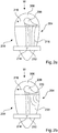
- Fig. 2a shows a wind energy installation 200 according to Fig. 1 in a plan view, the rotor 206 rotatably fastened to the nacelle 204 having only one of the three rotor blades 208 in a 12 o'clock position for the purpose of illustration.
- an instrument carrier 212 is fastened above and on the gondola 204, which has an acoustic sensor 214, in particular a monitoring device 214 according to the invention.
- the rotor blade 208 is arranged together with the rotor 206 so as to be rotatable relative to the rest of the nacelle 204. Due to the wind W, the rotor blade 208 rotates in the direction of rotation 216 indicated by the arrow. In this case, the rotor blade 208 causes a flow separation 218 which, viewed from the wind direction W, lies behind the rotor blade 208. It should be noted that the illustration is schematic and, in particular, only shows the flow separation schematically.
- the laminar flow separation 218, shown here only in a simplified manner, can be measured in the form of a noise and is detected by the acoustic sensor 214, which is designed as a microphone.
- the stall 220 can vary depending on the angle of attack and the position of the rotor blade 208 in relation to the wind W.
- the separation of the laminar flow takes place at another point on the rotor blade surface or the laminar flow changes over to a turbulent flow on the rotor blade.
- Such and further changes in the stall which are caused in particular by the pitch angle, can be detected and evaluated according to the invention by the acoustic sensor.
- FIG. 2b that essentially Fig. 2a corresponds, shows the same illustration of a wind energy installation 200 according to FIG Fig. 1 , wherein the rotor blade 208 has an icing 230, which can also be referred to as ice formation 230.
- the ice formation 230 causes a changed flow stall 238, which is also only shown in a simplified manner.
- This changed flow separation 238 can also be measured in the form of a noise and is recorded by the microphone 214.
- the noise recorded in this way differs recognizably from the noise of an ice-free rotor blade, so that the formation of ice 230 on the rotor blade 208 is recognized by a simple comparison.
- FIG. 2a shows only one example for the detection of an operating state of an operating means of a wind energy installation.
- the acoustic sensor and the proposed methods are also suitable for detecting further operating states of other operating resources, such as the generator and the nacelle. The detection of further operating states can therefore take place at the same time using the same recorded noise.
- Fig. 3 illustrates in an overview 300 a method for monitoring a wind energy installation according to a preferred embodiment, the wind energy installation having an acoustic sensor outside and on, in particular on, the nacelle for monitoring an operating state of the wind energy installation.
- the acoustic sensor is switched on in response to a signal, an internal signal from the wind energy installation 301 or an external signal from the control room 302 being used as the signal.
- the acoustic sensor that is to say the microphone, begins to record the noise 306 that surrounds the nacelle of the wind energy installation.
- the recording 306 is then transferred 307 to a filter in order to eliminate interfering signals in the recording.
- the filtering 308 takes place either internally, namely in particular in the monitoring device having the sensor.
- the monitoring device comprises at least one sensor and can furthermore also comprise a filter and an evaluation unit.
- the filtering can be done externally in a control room.
- the recorded noise is then transmitted to the control room using a stream, for example via W-LAN.
- the noise is evaluated.
- a spectral analysis is carried out in which the recorded and filtered noise is broken down into individual frequency bands. These frequency bands can then be aligned with known frequency bands. In the event of a discrepancy between these frequency bands, an interference signal 311 would then be output, which is processed further.
- the fault signal 311 can be implemented, for example, by a warning signal in the control room, the staff in the control room then being able to initiate further steps in order to remedy the fault.
- Fig. 4 illustrates in an overview 400 a method for controlling a wind turbine according to a preferred embodiment, wherein the wind turbine for controlling has an acoustic sensor on the nacelle and comprises a previously described method for monitoring a wind turbine, and wherein the Wind turbine is controlled externally depending on the recorded noise.
- a control room that is to say an external monitoring point, switches to a monitoring device located on the wind power plant at 401, the monitoring device comprising an acoustic sensor which is arranged on the nacelle of the wind power plant.
- the acoustic sensor which is designed as a microphone, picks up the noise surrounding the gondola and sends it to the control room.
- the recording 404 is thus transmitted 405 to the control room.
- noise is filtered 406 and then evaluated 408, for example by a spectral analysis.
- the evaluation 408 determines whether there is a malfunction in an operating means of the wind energy installation 409. If there is no malfunction, the control room can either switch off 420 from the sensor or continue to transmit the noise 421 with the help of a database, the most favorable control variable for controlling the wind turbine is calculated. The corresponding operating means is then controlled by means of this control variable 411.
- control room detects an incorrect flow stall on the wind turbine and then controls the azimuth angle of the nacelle accordingly.
- the wind energy installation is at a standstill and the control room switches to the microphone before the installation is started up.
- the control room detects icing on the rotor blades and decides in a comparison 410 either to deice the blades by means of a heater or not to start up the system yet.
- Fig. 5 shows a schematic evaluation, in particular a spectral analysis, of a recorded noise 500.
- a noise 502 surrounding the nacelle of the wind energy installation is first recorded by means of a microphone arranged on the nacelle of the wind energy installation.
- the noise recorded in this way is then filtered into a substantially interference-free noise 504. This can be done, for example, by high-pass and / or low-pass filters.
- the filtered noise is then broken down into specific frequency bands 510 and 520 by means of a spectral analysis.
- the division into two frequency bands is only intended to simplify the principle; the evaluation is not limited to such a division into two bands.
- the determined frequency bands 510 and 520 are aligned with the known frequency bands 512 and 522.
- the frequency band 510 corresponds, for example, to the frequency band 510 of the recorded noise of the rotor blades and the frequency band 520 to the frequency band 520 of the recorded noise of the azimuth adjustment. These are compared with the frequency bands 512 and 522 known for the rotor blades and the azimuth adjustment.
- the known frequency bands can, for example, be determined ex works by simulation or on-site measurements. However, iterative determination of the known frequency bands 512 and 522 while the wind energy installation is in operation is also possible.
- Fig. 5 an example is shown, and there the recorded frequency band 520 of the azimuth adjustment has a deviation from the known frequency band 522 of the azimuth adjustment. This deviation is now transferred to evaluation logic 530, which triggers a preferred control signal 531. For example, the angle of incidence of the rotor blades is changed in order to correct the detected deviation.
Landscapes
- Engineering & Computer Science (AREA)
- Life Sciences & Earth Sciences (AREA)
- Sustainable Development (AREA)
- Sustainable Energy (AREA)
- Chemical & Material Sciences (AREA)
- Combustion & Propulsion (AREA)
- Mechanical Engineering (AREA)
- General Engineering & Computer Science (AREA)
- Physics & Mathematics (AREA)
- Fluid Mechanics (AREA)
- Wind Motors (AREA)
Claims (15)
- Procédé pour surveiller une éolienne avec une nacelle, comprenant les étapes :- d'enregistrement d'un bruit au moyen d'au moins un capteur acoustique disposé à l'extérieur et au niveau de la nacelle,- d'évaluation du bruit enregistré pour identifier un état de pale de rotor de l'éolienne, dans lequel- l'enregistrement et l'évaluation du bruit sont effectués lorsque l'éolienne est à l'arrêt.
- Procédé selon la revendication 1, caractérisé en ce que le capteur acoustique est disposé sur la nacelle.
- Procédé selon l'une quelconque des revendications 1 ou 2, caractérisé en ce que, pour identifier l'état de fonctionnement, un niveau d'émissions sonores de l'éolienne est enregistré.
- Procédé selon l'une quelconque des revendications précédentes, caractérisé en ce que l'enregistrement du bruit est effectué avec une sensibilité à la direction.
- Procédé selon l'une quelconque des revendications précédentes, caractérisé en ce que l'enregistrement du bruit est effectué dans au moins une bande de fréquences, dans laquelle apparaissent des bruits, qui sont à associer à une formation de gel au niveau de la pale de rotor.
- Procédé selon l'une quelconque des revendications précédentes, caractérisé en ce que l'évaluation du bruit enregistré pour identifier l'état de fonctionnement est effectuée de manière externe, en particulier par un poste de surveillance.
- Procédé selon l'une quelconque des revendications précédentes, caractérisé en ce que l'évaluation du bruit enregistré pour identifier l'état de fonctionnement est effectuée au moyen d'une analyse spectrale.
- Dispositif de surveillance pour surveiller une éolienne avec une nacelle, comprenant- un capteur acoustique disposé à l'extérieur ou au niveau de la nacelle, pour enregistrer un bruit, et- un système d'évaluation pour évaluer le bruit enregistré à l'arrêt pour identifier un état de fonctionnement de l'éolienne, dans lequel- le système d'évaluation est mis au point pour exécuter un procédé selon l'une quelconque des revendications 1 à 7.
- Dispositif de surveillance selon la revendication 8, caractérisé en ce que
le capteur acoustique présente plusieurs microphones. - Dispositif de surveillance selon la revendication 9, caractérisé en ce que le capteur acoustique présente un réseau de microphones.
- Dispositif de surveillance selon l'une quelconque des revendications 8 à 10, caractérisé en ce qu'une interface de données est prévue pour l'échange de données.
- Dispositif de surveillance selon la revendication 11, caractérisé en ce que l'interface de données est prévue pour transmettre des données enregistrées par le capteur acoustique et/ou pour transmettre des données évaluées par le système d'évaluation.
- Éolienne avec une nacelle et au moins un capteur acoustique disposé à l'extérieur au niveau de la nacelle, pour enregistrer des bruits, caractérisée en ce que- un dispositif de surveillance selon l'une quelconque des revendications 8 à 12 est utilisé, et/ou- qu'un procédé selon l'une quelconque des revendications 1 à 7 est exécuté.
- Parc éolien comprenant au moins deux éoliennes, dans lequel au moins une éolienne selon la revendication 13 est utilisée et/ou un procédé selon l'une quelconque des revendications 1 à 7 est mis en œuvre.
- Parc éolien avec au moins deux éoliennes, dans lequel les éoliennes sont interconnectées entre elles et sont préparées pour échanger des données par l'intermédiaire d'au moins un dispositif de surveillance selon l'une quelconque des revendications 8 à 12.
Applications Claiming Priority (2)
| Application Number | Priority Date | Filing Date | Title |
|---|---|---|---|
| DE102015117032.9A DE102015117032A1 (de) | 2015-10-07 | 2015-10-07 | Verfahren zum Überwachen einer Windenergieanlage |
| PCT/EP2016/074004 WO2017060430A1 (fr) | 2015-10-07 | 2016-10-07 | Procédé de surveillance d'une éolienne |
Publications (2)
| Publication Number | Publication Date |
|---|---|
| EP3359810A1 EP3359810A1 (fr) | 2018-08-15 |
| EP3359810B1 true EP3359810B1 (fr) | 2021-11-10 |
Family
ID=57104035
Family Applications (1)
| Application Number | Title | Priority Date | Filing Date |
|---|---|---|---|
| EP16778035.2A Active EP3359810B1 (fr) | 2015-10-07 | 2016-10-07 | Procédé de surveillance d'une éolienne |
Country Status (8)
| Country | Link |
|---|---|
| US (1) | US20190032641A1 (fr) |
| EP (1) | EP3359810B1 (fr) |
| JP (1) | JP2018529883A (fr) |
| CN (1) | CN108138750A (fr) |
| BR (1) | BR112018006564A2 (fr) |
| CA (1) | CA2999829C (fr) |
| DE (1) | DE102015117032A1 (fr) |
| WO (1) | WO2017060430A1 (fr) |
Families Citing this family (13)
| Publication number | Priority date | Publication date | Assignee | Title |
|---|---|---|---|---|
| CN109209783A (zh) * | 2018-09-18 | 2019-01-15 | 远景能源(江苏)有限公司 | 一种基于噪声检测叶片的雷击损伤的方法及装置 |
| EP3667062A1 (fr) | 2018-12-13 | 2020-06-17 | Siemens Gamesa Renewable Energy A/S | Dispositif de contrôle de l'humidité dans des éoliennes |
| EP3667081A1 (fr) * | 2018-12-13 | 2020-06-17 | Siemens Gamesa Renewable Energy A/S | Régulation de flux de pale d'éolienne |
| EP3832132B1 (fr) * | 2019-12-06 | 2023-06-07 | Wobben Properties GmbH | Dispositif de maintenance mobile, dispositif de montage mobile et procédé |
| CN111306008B (zh) | 2019-12-31 | 2022-03-11 | 远景智能国际私人投资有限公司 | 风机叶片的检测方法、装置、设备及存储介质 |
| EP3875752A1 (fr) * | 2020-03-05 | 2021-09-08 | Siemens Gamesa Renewable Energy A/S | Procédé et dispositif pour commander une éolienne pour réduire le bruit |
| DE102020114222A1 (de) * | 2020-05-27 | 2021-12-02 | Vacon Oy | Antrieb für eine elektrische Anwendung und Verfahren zur Aufrechterhaltung und Feinabstimmung des Antriebs |
| EP4179198A4 (fr) | 2020-07-13 | 2024-03-20 | Windesco, Inc. | Procédés et systèmes de commande avancée du lacet d'une éolienne |
| ES3058674T3 (en) * | 2021-12-07 | 2026-03-12 | General Electric Renovables Espana Sl | A method for operating a wind turbine and a wind turbine |
| ES2943569B2 (es) * | 2021-12-14 | 2024-01-15 | Altran Innovacion S L | Sistema y procedimiento de detección de irregularidades en las palas de un aerogenerador |
| EP4317680A1 (fr) * | 2022-08-05 | 2024-02-07 | Christoph Lucks | Procédé de détection d'un déséquilibre d'une éolienne et de génération du courant au moyen de l'éolienne |
| DE102023212390A1 (de) | 2023-12-08 | 2025-06-12 | Robert Bosch Gesellschaft mit beschränkter Haftung | Verfahren zur akustischen Überwachung eines Rotorblatts einer Windenergieanlage und akustisch überwachte Windenergieanlage |
| DE102023212392A1 (de) | 2023-12-08 | 2025-06-12 | Robert Bosch Gesellschaft mit beschränkter Haftung | Verfahren und Vorrichtung zur akustischen Überwachung eines Windparks und akustisch überwachter Windpark |
Family Cites Families (17)
| Publication number | Priority date | Publication date | Assignee | Title |
|---|---|---|---|---|
| JPH07279815A (ja) * | 1994-04-06 | 1995-10-27 | Koyo Seiko Co Ltd | 風力発電装置 |
| DE20021970U1 (de) | 2000-12-30 | 2001-04-05 | Igus Ingenieurgemeinschaft Umweltschutz Meß-und Verfahrenstechnik GmbH, 01099 Dresden | Einrichtung zur Überwachung des Zustandes von Rotorblättern an Windkraftanlagen |
| DE10115267C2 (de) * | 2001-03-28 | 2003-06-18 | Aloys Wobben | Verfahren zur Überwachung einer Windenergieanlage |
| US7086834B2 (en) * | 2004-06-10 | 2006-08-08 | General Electric Company | Methods and apparatus for rotor blade ice detection |
| US7487673B2 (en) * | 2006-12-13 | 2009-02-10 | General Electric Company | Ice detection based on anemometry |
| US8021110B2 (en) * | 2007-01-05 | 2011-09-20 | General Electric Company | Tonal emission control for wind turbines |
| US7895018B2 (en) * | 2007-08-10 | 2011-02-22 | General Electric Company | Event monitoring via combination of signals |
| US8277185B2 (en) * | 2007-12-28 | 2012-10-02 | General Electric Company | Wind turbine, wind turbine controller and method for controlling a wind turbine |
| US8215905B2 (en) * | 2007-12-31 | 2012-07-10 | General Electric Corporation | Methods and apparatus for error reduction in rotor loading measurements |
| DE102008026842B3 (de) * | 2008-06-05 | 2010-02-18 | Repower Systems Ag | Verfahren und Anordnung zum Überwachen des Betriebs einer Windenergieanlage |
| US7896613B2 (en) * | 2009-06-03 | 2011-03-01 | General Electric Company | System and method for wind turbine noise control and damage detection |
| US20100119370A1 (en) * | 2009-11-17 | 2010-05-13 | Modi Vivendi As | Intelligent and optimized wind turbine system for harsh environmental conditions |
| WO2011117246A2 (fr) * | 2010-03-23 | 2011-09-29 | Vestas Wind Systems A/S | Méthode de dégivrage des pales d'une turbine éolienne et turbine éolienne avec système de dégivrage |
| CN103797244B (zh) * | 2011-08-16 | 2017-09-12 | 维斯塔斯风力系统集团公司 | 用于风力涡轮机的声噪声监测系统 |
| EP2594912A1 (fr) * | 2011-11-21 | 2013-05-22 | Eurocopter Deutschland GmbH | Système de détection pour la détection de dommages sur des composants rotatifs d'avion et procédé de fonctionnement d'un tel système de détection |
| US8757003B1 (en) * | 2011-12-15 | 2014-06-24 | Shaw Shahriar Makaremi | Multi-frequency-band blade condition monitoring system |
| US9528493B2 (en) * | 2013-05-28 | 2016-12-27 | Siemens Aktiengesellschaft | Apparatus to detect aerodynamic conditions of blades of wind turbines |
-
2015
- 2015-10-07 DE DE102015117032.9A patent/DE102015117032A1/de not_active Withdrawn
-
2016
- 2016-10-07 CA CA2999829A patent/CA2999829C/fr not_active Expired - Fee Related
- 2016-10-07 CN CN201680058911.7A patent/CN108138750A/zh active Pending
- 2016-10-07 JP JP2018517768A patent/JP2018529883A/ja active Pending
- 2016-10-07 US US15/765,677 patent/US20190032641A1/en not_active Abandoned
- 2016-10-07 EP EP16778035.2A patent/EP3359810B1/fr active Active
- 2016-10-07 BR BR112018006564-1A patent/BR112018006564A2/pt not_active Application Discontinuation
- 2016-10-07 WO PCT/EP2016/074004 patent/WO2017060430A1/fr not_active Ceased
Non-Patent Citations (1)
| Title |
|---|
| None * |
Also Published As
| Publication number | Publication date |
|---|---|
| CA2999829C (fr) | 2020-12-29 |
| DE102015117032A1 (de) | 2017-04-13 |
| WO2017060430A1 (fr) | 2017-04-13 |
| EP3359810A1 (fr) | 2018-08-15 |
| JP2018529883A (ja) | 2018-10-11 |
| CA2999829A1 (fr) | 2017-04-13 |
| CN108138750A (zh) | 2018-06-08 |
| US20190032641A1 (en) | 2019-01-31 |
| BR112018006564A2 (pt) | 2018-10-16 |
Similar Documents
| Publication | Publication Date | Title |
|---|---|---|
| EP3359810B1 (fr) | Procédé de surveillance d'une éolienne | |
| DE102011116961B4 (de) | Verfahren zur Bestimmung einer mechanischen Beschädigung eines Rotorblatts einer Windenergieanlage | |
| EP2565444B1 (fr) | Procédé et dispositif de surveillance d'état de pales de rotor | |
| EP2021890B1 (fr) | Procede de surveillance des contraintes de pales de rotor d'eoliennes | |
| DE102008026842B3 (de) | Verfahren und Anordnung zum Überwachen des Betriebs einer Windenergieanlage | |
| EP1792077B1 (fr) | Procede et dispositif pour surveiller l'etat d'ailettes de rotors dans des installations eoliennes | |
| WO2002053910A1 (fr) | Procede et dispositif servant a surveiller l'etat de pales de rotor d'installations eoliennes | |
| DE10065314B4 (de) | Verfahren und Einrichtung zur Überwachung des Zustandes von Rotorblättern an Windkraftanlagen | |
| DE102006054667B4 (de) | Kollisionswarnsystem für eine Windenergieanlage | |
| DE102009030886A1 (de) | Windenergieanlage mit einer Vielzahl von Windenergievorrichtungen und Verfahren zur Steuerung der Windenergieanlage | |
| EP2404059A2 (fr) | Procédé de surveillance d'éoliennes | |
| DE102008048956A1 (de) | Verfahren zum Überwachen eines Getriebes einer Windenergieanlage | |
| DE102015200163A1 (de) | Störungsgrad-Bestimmungssystem und Verfahren für einen Windturbinengenerator | |
| DE202013007142U1 (de) | Vorrichtung zur Zustandsüberwachung von Windenergieanlagen | |
| EP3715626B1 (fr) | Procédé de détermination d'une courbe de performance d'une éolienne et éolienne correspondante | |
| WO2016091933A1 (fr) | Procédé et dispositif pour surveiller une éolienne | |
| WO2017215797A1 (fr) | Procédé de surveillance d'un réglage de pales de rotor | |
| EP2674616B1 (fr) | Dispositif de commande d'installation éolienne et système de commande d'un parc éolien | |
| DE202008006322U1 (de) | Windkraftanlage | |
| EP4182557A1 (fr) | Dispositif d'identification d'une accumulation de glace sur des pales de rotor d'une éolienne et procédé d'entraînement d'un tel dispositif | |
| DE102009059668A1 (de) | Windenergieanlage und Verfahren zum Steuern einer solchen | |
| DE102023212390A1 (de) | Verfahren zur akustischen Überwachung eines Rotorblatts einer Windenergieanlage und akustisch überwachte Windenergieanlage | |
| DE102015211517A1 (de) | Mobiles Gerät zur Durchführung von Instandhaltungsmaßnahmen an einer Windenergieanlage | |
| DE102022214018A1 (de) | Anordnung und Verfahren zur Überwachung eines elektrisch angetriebenen Systems und System, insbesondere Windenergieanlage, mit einer solchen Anordnung | |
| EP1985849B1 (fr) | Procédé de fonctionnement d'une éolienne et éolienne |
Legal Events
| Date | Code | Title | Description |
|---|---|---|---|
| STAA | Information on the status of an ep patent application or granted ep patent |
Free format text: STATUS: THE INTERNATIONAL PUBLICATION HAS BEEN MADE |
|
| PUAI | Public reference made under article 153(3) epc to a published international application that has entered the european phase |
Free format text: ORIGINAL CODE: 0009012 |
|
| STAA | Information on the status of an ep patent application or granted ep patent |
Free format text: STATUS: REQUEST FOR EXAMINATION WAS MADE |
|
| 17P | Request for examination filed |
Effective date: 20180507 |
|
| AK | Designated contracting states |
Kind code of ref document: A1 Designated state(s): AL AT BE BG CH CY CZ DE DK EE ES FI FR GB GR HR HU IE IS IT LI LT LU LV MC MK MT NL NO PL PT RO RS SE SI SK SM TR |
|
| AX | Request for extension of the european patent |
Extension state: BA ME |
|
| DAV | Request for validation of the european patent (deleted) | ||
| DAX | Request for extension of the european patent (deleted) | ||
| REG | Reference to a national code |
Ref country code: DE Ref legal event code: R079 Ref document number: 502016014142 Country of ref document: DE Free format text: PREVIOUS MAIN CLASS: F03D0007040000 Ipc: F03D0017000000 |
|
| GRAP | Despatch of communication of intention to grant a patent |
Free format text: ORIGINAL CODE: EPIDOSNIGR1 |
|
| STAA | Information on the status of an ep patent application or granted ep patent |
Free format text: STATUS: GRANT OF PATENT IS INTENDED |
|
| RIC1 | Information provided on ipc code assigned before grant |
Ipc: F03D 80/40 20160101ALI20200214BHEP Ipc: F03D 17/00 20160101AFI20200214BHEP |
|
| INTG | Intention to grant announced |
Effective date: 20200310 |
|
| GRAJ | Information related to disapproval of communication of intention to grant by the applicant or resumption of examination proceedings by the epo deleted |
Free format text: ORIGINAL CODE: EPIDOSDIGR1 |
|
| STAA | Information on the status of an ep patent application or granted ep patent |
Free format text: STATUS: REQUEST FOR EXAMINATION WAS MADE |
|
| STAA | Information on the status of an ep patent application or granted ep patent |
Free format text: STATUS: EXAMINATION IS IN PROGRESS |
|
| INTC | Intention to grant announced (deleted) | ||
| 17Q | First examination report despatched |
Effective date: 20200703 |
|
| GRAS | Grant fee paid |
Free format text: ORIGINAL CODE: EPIDOSNIGR3 |
|
| STAA | Information on the status of an ep patent application or granted ep patent |
Free format text: STATUS: GRANT OF PATENT IS INTENDED |
|
| GRAP | Despatch of communication of intention to grant a patent |
Free format text: ORIGINAL CODE: EPIDOSNIGR1 |
|
| GRAJ | Information related to disapproval of communication of intention to grant by the applicant or resumption of examination proceedings by the epo deleted |
Free format text: ORIGINAL CODE: EPIDOSDIGR1 |
|
| GRAL | Information related to payment of fee for publishing/printing deleted |
Free format text: ORIGINAL CODE: EPIDOSDIGR3 |
|
| STAA | Information on the status of an ep patent application or granted ep patent |
Free format text: STATUS: EXAMINATION IS IN PROGRESS |
|
| INTG | Intention to grant announced |
Effective date: 20210304 |
|
| GRAP | Despatch of communication of intention to grant a patent |
Free format text: ORIGINAL CODE: EPIDOSNIGR1 |
|
| STAA | Information on the status of an ep patent application or granted ep patent |
Free format text: STATUS: GRANT OF PATENT IS INTENDED |
|
| INTC | Intention to grant announced (deleted) | ||
| INTG | Intention to grant announced |
Effective date: 20210419 |
|
| GRAA | (expected) grant |
Free format text: ORIGINAL CODE: 0009210 |
|
| STAA | Information on the status of an ep patent application or granted ep patent |
Free format text: STATUS: THE PATENT HAS BEEN GRANTED |
|
| AK | Designated contracting states |
Kind code of ref document: B1 Designated state(s): AL AT BE BG CH CY CZ DE DK EE ES FI FR GB GR HR HU IE IS IT LI LT LU LV MC MK MT NL NO PL PT RO RS SE SI SK SM TR |
|
| REG | Reference to a national code |
Ref country code: GB Ref legal event code: FG4D Free format text: NOT ENGLISH |
|
| REG | Reference to a national code |
Ref country code: AT Ref legal event code: REF Ref document number: 1446327 Country of ref document: AT Kind code of ref document: T Effective date: 20211115 Ref country code: CH Ref legal event code: EP |
|
| REG | Reference to a national code |
Ref country code: DE Ref legal event code: R096 Ref document number: 502016014142 Country of ref document: DE |
|
| REG | Reference to a national code |
Ref country code: DK Ref legal event code: T3 Effective date: 20211126 |
|
| REG | Reference to a national code |
Ref country code: IE Ref legal event code: FG4D Free format text: LANGUAGE OF EP DOCUMENT: GERMAN |
|
| REG | Reference to a national code |
Ref country code: NL Ref legal event code: FP |
|
| REG | Reference to a national code |
Ref country code: LT Ref legal event code: MG9D |
|
| PG25 | Lapsed in a contracting state [announced via postgrant information from national office to epo] |
Ref country code: RS Free format text: LAPSE BECAUSE OF FAILURE TO SUBMIT A TRANSLATION OF THE DESCRIPTION OR TO PAY THE FEE WITHIN THE PRESCRIBED TIME-LIMIT Effective date: 20211110 Ref country code: LT Free format text: LAPSE BECAUSE OF FAILURE TO SUBMIT A TRANSLATION OF THE DESCRIPTION OR TO PAY THE FEE WITHIN THE PRESCRIBED TIME-LIMIT Effective date: 20211110 Ref country code: FI Free format text: LAPSE BECAUSE OF FAILURE TO SUBMIT A TRANSLATION OF THE DESCRIPTION OR TO PAY THE FEE WITHIN THE PRESCRIBED TIME-LIMIT Effective date: 20211110 Ref country code: BG Free format text: LAPSE BECAUSE OF FAILURE TO SUBMIT A TRANSLATION OF THE DESCRIPTION OR TO PAY THE FEE WITHIN THE PRESCRIBED TIME-LIMIT Effective date: 20220210 |
|
| PG25 | Lapsed in a contracting state [announced via postgrant information from national office to epo] |
Ref country code: IS Free format text: LAPSE BECAUSE OF FAILURE TO SUBMIT A TRANSLATION OF THE DESCRIPTION OR TO PAY THE FEE WITHIN THE PRESCRIBED TIME-LIMIT Effective date: 20220310 Ref country code: SE Free format text: LAPSE BECAUSE OF FAILURE TO SUBMIT A TRANSLATION OF THE DESCRIPTION OR TO PAY THE FEE WITHIN THE PRESCRIBED TIME-LIMIT Effective date: 20211110 Ref country code: PT Free format text: LAPSE BECAUSE OF FAILURE TO SUBMIT A TRANSLATION OF THE DESCRIPTION OR TO PAY THE FEE WITHIN THE PRESCRIBED TIME-LIMIT Effective date: 20220310 Ref country code: PL Free format text: LAPSE BECAUSE OF FAILURE TO SUBMIT A TRANSLATION OF THE DESCRIPTION OR TO PAY THE FEE WITHIN THE PRESCRIBED TIME-LIMIT Effective date: 20211110 Ref country code: NO Free format text: LAPSE BECAUSE OF FAILURE TO SUBMIT A TRANSLATION OF THE DESCRIPTION OR TO PAY THE FEE WITHIN THE PRESCRIBED TIME-LIMIT Effective date: 20220210 Ref country code: LV Free format text: LAPSE BECAUSE OF FAILURE TO SUBMIT A TRANSLATION OF THE DESCRIPTION OR TO PAY THE FEE WITHIN THE PRESCRIBED TIME-LIMIT Effective date: 20211110 Ref country code: HR Free format text: LAPSE BECAUSE OF FAILURE TO SUBMIT A TRANSLATION OF THE DESCRIPTION OR TO PAY THE FEE WITHIN THE PRESCRIBED TIME-LIMIT Effective date: 20211110 Ref country code: GR Free format text: LAPSE BECAUSE OF FAILURE TO SUBMIT A TRANSLATION OF THE DESCRIPTION OR TO PAY THE FEE WITHIN THE PRESCRIBED TIME-LIMIT Effective date: 20220211 Ref country code: ES Free format text: LAPSE BECAUSE OF FAILURE TO SUBMIT A TRANSLATION OF THE DESCRIPTION OR TO PAY THE FEE WITHIN THE PRESCRIBED TIME-LIMIT Effective date: 20211110 |
|
| PG25 | Lapsed in a contracting state [announced via postgrant information from national office to epo] |
Ref country code: SM Free format text: LAPSE BECAUSE OF FAILURE TO SUBMIT A TRANSLATION OF THE DESCRIPTION OR TO PAY THE FEE WITHIN THE PRESCRIBED TIME-LIMIT Effective date: 20211110 Ref country code: SK Free format text: LAPSE BECAUSE OF FAILURE TO SUBMIT A TRANSLATION OF THE DESCRIPTION OR TO PAY THE FEE WITHIN THE PRESCRIBED TIME-LIMIT Effective date: 20211110 Ref country code: RO Free format text: LAPSE BECAUSE OF FAILURE TO SUBMIT A TRANSLATION OF THE DESCRIPTION OR TO PAY THE FEE WITHIN THE PRESCRIBED TIME-LIMIT Effective date: 20211110 Ref country code: EE Free format text: LAPSE BECAUSE OF FAILURE TO SUBMIT A TRANSLATION OF THE DESCRIPTION OR TO PAY THE FEE WITHIN THE PRESCRIBED TIME-LIMIT Effective date: 20211110 Ref country code: CZ Free format text: LAPSE BECAUSE OF FAILURE TO SUBMIT A TRANSLATION OF THE DESCRIPTION OR TO PAY THE FEE WITHIN THE PRESCRIBED TIME-LIMIT Effective date: 20211110 |
|
| REG | Reference to a national code |
Ref country code: DE Ref legal event code: R097 Ref document number: 502016014142 Country of ref document: DE |
|
| PLBE | No opposition filed within time limit |
Free format text: ORIGINAL CODE: 0009261 |
|
| STAA | Information on the status of an ep patent application or granted ep patent |
Free format text: STATUS: NO OPPOSITION FILED WITHIN TIME LIMIT |
|
| 26N | No opposition filed |
Effective date: 20220811 |
|
| PG25 | Lapsed in a contracting state [announced via postgrant information from national office to epo] |
Ref country code: AL Free format text: LAPSE BECAUSE OF FAILURE TO SUBMIT A TRANSLATION OF THE DESCRIPTION OR TO PAY THE FEE WITHIN THE PRESCRIBED TIME-LIMIT Effective date: 20211110 |
|
| PG25 | Lapsed in a contracting state [announced via postgrant information from national office to epo] |
Ref country code: SI Free format text: LAPSE BECAUSE OF FAILURE TO SUBMIT A TRANSLATION OF THE DESCRIPTION OR TO PAY THE FEE WITHIN THE PRESCRIBED TIME-LIMIT Effective date: 20211110 |
|
| PG25 | Lapsed in a contracting state [announced via postgrant information from national office to epo] |
Ref country code: MC Free format text: LAPSE BECAUSE OF FAILURE TO SUBMIT A TRANSLATION OF THE DESCRIPTION OR TO PAY THE FEE WITHIN THE PRESCRIBED TIME-LIMIT Effective date: 20211110 Ref country code: IT Free format text: LAPSE BECAUSE OF FAILURE TO SUBMIT A TRANSLATION OF THE DESCRIPTION OR TO PAY THE FEE WITHIN THE PRESCRIBED TIME-LIMIT Effective date: 20211110 |
|
| REG | Reference to a national code |
Ref country code: CH Ref legal event code: PL |
|
| REG | Reference to a national code |
Ref country code: BE Ref legal event code: MM Effective date: 20221031 |
|
| PG25 | Lapsed in a contracting state [announced via postgrant information from national office to epo] |
Ref country code: LU Free format text: LAPSE BECAUSE OF NON-PAYMENT OF DUE FEES Effective date: 20221007 |
|
| PG25 | Lapsed in a contracting state [announced via postgrant information from national office to epo] |
Ref country code: LI Free format text: LAPSE BECAUSE OF NON-PAYMENT OF DUE FEES Effective date: 20221031 Ref country code: CH Free format text: LAPSE BECAUSE OF NON-PAYMENT OF DUE FEES Effective date: 20221031 |
|
| PG25 | Lapsed in a contracting state [announced via postgrant information from national office to epo] |
Ref country code: BE Free format text: LAPSE BECAUSE OF NON-PAYMENT OF DUE FEES Effective date: 20221031 |
|
| PG25 | Lapsed in a contracting state [announced via postgrant information from national office to epo] |
Ref country code: IE Free format text: LAPSE BECAUSE OF NON-PAYMENT OF DUE FEES Effective date: 20221007 |
|
| REG | Reference to a national code |
Ref country code: AT Ref legal event code: MM01 Ref document number: 1446327 Country of ref document: AT Kind code of ref document: T Effective date: 20221007 |
|
| PG25 | Lapsed in a contracting state [announced via postgrant information from national office to epo] |
Ref country code: AT Free format text: LAPSE BECAUSE OF NON-PAYMENT OF DUE FEES Effective date: 20221007 |
|
| PG25 | Lapsed in a contracting state [announced via postgrant information from national office to epo] |
Ref country code: HU Free format text: LAPSE BECAUSE OF FAILURE TO SUBMIT A TRANSLATION OF THE DESCRIPTION OR TO PAY THE FEE WITHIN THE PRESCRIBED TIME-LIMIT; INVALID AB INITIO Effective date: 20161007 |
|
| PG25 | Lapsed in a contracting state [announced via postgrant information from national office to epo] |
Ref country code: CY Free format text: LAPSE BECAUSE OF FAILURE TO SUBMIT A TRANSLATION OF THE DESCRIPTION OR TO PAY THE FEE WITHIN THE PRESCRIBED TIME-LIMIT Effective date: 20211110 |
|
| PG25 | Lapsed in a contracting state [announced via postgrant information from national office to epo] |
Ref country code: MK Free format text: LAPSE BECAUSE OF FAILURE TO SUBMIT A TRANSLATION OF THE DESCRIPTION OR TO PAY THE FEE WITHIN THE PRESCRIBED TIME-LIMIT Effective date: 20211110 |
|
| PG25 | Lapsed in a contracting state [announced via postgrant information from national office to epo] |
Ref country code: TR Free format text: LAPSE BECAUSE OF FAILURE TO SUBMIT A TRANSLATION OF THE DESCRIPTION OR TO PAY THE FEE WITHIN THE PRESCRIBED TIME-LIMIT Effective date: 20211110 |
|
| PG25 | Lapsed in a contracting state [announced via postgrant information from national office to epo] |
Ref country code: MT Free format text: LAPSE BECAUSE OF FAILURE TO SUBMIT A TRANSLATION OF THE DESCRIPTION OR TO PAY THE FEE WITHIN THE PRESCRIBED TIME-LIMIT Effective date: 20211110 |
|
| PGFP | Annual fee paid to national office [announced via postgrant information from national office to epo] |
Ref country code: NL Payment date: 20241023 Year of fee payment: 9 |
|
| PGFP | Annual fee paid to national office [announced via postgrant information from national office to epo] |
Ref country code: DE Payment date: 20241107 Year of fee payment: 9 |
|
| PGFP | Annual fee paid to national office [announced via postgrant information from national office to epo] |
Ref country code: DK Payment date: 20241023 Year of fee payment: 9 |
|
| PGFP | Annual fee paid to national office [announced via postgrant information from national office to epo] |
Ref country code: GB Payment date: 20241024 Year of fee payment: 9 |
|
| PGFP | Annual fee paid to national office [announced via postgrant information from national office to epo] |
Ref country code: FR Payment date: 20241024 Year of fee payment: 9 |