EP3359874B1 - Anordnung zur lichtabgabe - Google Patents
Anordnung zur lichtabgabe Download PDFInfo
- Publication number
- EP3359874B1 EP3359874B1 EP16778064.2A EP16778064A EP3359874B1 EP 3359874 B1 EP3359874 B1 EP 3359874B1 EP 16778064 A EP16778064 A EP 16778064A EP 3359874 B1 EP3359874 B1 EP 3359874B1
- Authority
- EP
- European Patent Office
- Prior art keywords
- light
- lenses
- arrangement
- guide plate
- light guide
- Prior art date
- Legal status (The legal status is an assumption and is not a legal conclusion. Google has not performed a legal analysis and makes no representation as to the accuracy of the status listed.)
- Active
Links
Images

Classifications
-
- G—PHYSICS
- G02—OPTICS
- G02B—OPTICAL ELEMENTS, SYSTEMS OR APPARATUS
- G02B6/00—Light guides; Structural details of arrangements comprising light guides and other optical elements, e.g. couplings
- G02B6/0001—Light guides; Structural details of arrangements comprising light guides and other optical elements, e.g. couplings specially adapted for lighting devices or systems
- G02B6/0011—Light guides; Structural details of arrangements comprising light guides and other optical elements, e.g. couplings specially adapted for lighting devices or systems the light guides being planar or of plate-like form
- G02B6/0033—Means for improving the coupling-out of light from the light guide
- G02B6/005—Means for improving the coupling-out of light from the light guide provided by one optical element, or plurality thereof, placed on the light output side of the light guide
- G02B6/0053—Prismatic sheet or layer; Brightness enhancement element, sheet or layer
-
- G—PHYSICS
- G02—OPTICS
- G02B—OPTICAL ELEMENTS, SYSTEMS OR APPARATUS
- G02B6/00—Light guides; Structural details of arrangements comprising light guides and other optical elements, e.g. couplings
- G02B6/0001—Light guides; Structural details of arrangements comprising light guides and other optical elements, e.g. couplings specially adapted for lighting devices or systems
- G02B6/0011—Light guides; Structural details of arrangements comprising light guides and other optical elements, e.g. couplings specially adapted for lighting devices or systems the light guides being planar or of plate-like form
-
- F—MECHANICAL ENGINEERING; LIGHTING; HEATING; WEAPONS; BLASTING
- F21—LIGHTING
- F21V—FUNCTIONAL FEATURES OR DETAILS OF LIGHTING DEVICES OR SYSTEMS THEREOF; STRUCTURAL COMBINATIONS OF LIGHTING DEVICES WITH OTHER ARTICLES, NOT OTHERWISE PROVIDED FOR
- F21V13/00—Producing particular characteristics or distribution of the light emitted by means of a combination of elements specified in two or more of main groups F21V1/00 - F21V11/00
-
- F—MECHANICAL ENGINEERING; LIGHTING; HEATING; WEAPONS; BLASTING
- F21—LIGHTING
- F21V—FUNCTIONAL FEATURES OR DETAILS OF LIGHTING DEVICES OR SYSTEMS THEREOF; STRUCTURAL COMBINATIONS OF LIGHTING DEVICES WITH OTHER ARTICLES, NOT OTHERWISE PROVIDED FOR
- F21V5/00—Refractors for light sources
- F21V5/04—Refractors for light sources of lens shape
-
- G—PHYSICS
- G02—OPTICS
- G02B—OPTICAL ELEMENTS, SYSTEMS OR APPARATUS
- G02B6/00—Light guides; Structural details of arrangements comprising light guides and other optical elements, e.g. couplings
- G02B6/0001—Light guides; Structural details of arrangements comprising light guides and other optical elements, e.g. couplings specially adapted for lighting devices or systems
- G02B6/0011—Light guides; Structural details of arrangements comprising light guides and other optical elements, e.g. couplings specially adapted for lighting devices or systems the light guides being planar or of plate-like form
- G02B6/0033—Means for improving the coupling-out of light from the light guide
- G02B6/005—Means for improving the coupling-out of light from the light guide provided by one optical element, or plurality thereof, placed on the light output side of the light guide
- G02B6/0055—Reflecting element, sheet or layer
-
- G—PHYSICS
- G02—OPTICS
- G02B—OPTICAL ELEMENTS, SYSTEMS OR APPARATUS
- G02B6/00—Light guides; Structural details of arrangements comprising light guides and other optical elements, e.g. couplings
- G02B6/0001—Light guides; Structural details of arrangements comprising light guides and other optical elements, e.g. couplings specially adapted for lighting devices or systems
- G02B6/0096—Light guides; Structural details of arrangements comprising light guides and other optical elements, e.g. couplings specially adapted for lighting devices or systems the lights guides being of the hollow type
Definitions
- the present invention relates to an arrangement for emitting light which has a flat arrangement of lenses and light sources in the form of LEDs, the light of which is emitted via the lenses.
- lens-like optical elements for influencing the light output of a lamp is already well known from the prior art. Since the distribution of the emitted light can be influenced very well by appropriate shaping of the lenses, such optical elements offer the possibility of adapting the light emission in a targeted manner in the desired manner. This advantage is particularly important when using LEDs as light sources, since LEDs initially emit light in a very wide angular range and, accordingly, a targeted concentration and alignment of the emitted light is essential, for example to meet the requirements of efficient lighting of a workplace or the like can.
- an embodiment has proven to be preferred in which a multiplicity of lenses is used and an LED is individually assigned to each lens.
- the lens then specifically influences the light of the LED assigned to it. Since in this case the lens is positioned in a defined manner with respect to the LED, it can be ensured that the light is actually emitted within a desired angular range with the desired light distribution.
- Both the lenses and the LEDs are then usually arranged like a matrix, the lenses often being combined to form a one-piece optical element.
- other embodiments also belong to the current state of the art.
- JP 2004 227835 A discloses a lighting device in which an optical film (highly transparent optical plate) is applied to a transparent light guide plate.
- the film (plate) has on the one side facing the light guide plate a plurality of microprisms with a square conical profile, on the other side a plurality of microlenses which are arranged with or without gaps.
- the light is coupled into the light guide plate from the side, i.e. at the front.
- the optical plate has light decoupling structures (microprisms) which are arranged exclusively on the edge of the lens.
- U.S. 5,396,350 A discloses a backlighting device for a flat screen display, consisting of a light generating device and a transparent reflection device, in turn consisting of a first adhesion promoter layer, a substrate, a second adhesion promoter layer and an asymmetrical reflection means when light is coupled in or out on one side.
- the thickness of a substrate layer located in between is optimized in such a way that the divergence of the light reflected divergently on the microprisms is compensated for by the microlenses of a suitable focal length.
- US 2015/146132 A1 describes a planar light source device with which planar light with directivity (e.g. for backlighting) can be obtained.
- planar light with directivity e.g. for backlighting
- one of them discloses a plate-shaped cavity housing into which light from a plurality of light sources is coupled laterally, mixed and evenly distributed.
- Light which reaches one of the openings in the upper plate and generally leaves the housing in a divergent manner is collimated by lenses arranged directly above the openings, whereby it is then emitted essentially parallel to the optical axis of the lens.
- EP 2 184 628 A2 describes a lamp, e.g. B. to illuminate escape routes or workplaces with particular risk, in the form of a combination of light source (optical plate) and pictogram (diffuser).
- the luminaire therefore consists of a flat, translucent light guide plate, which has a light distribution structure on at least one side surface, formed from a plurality of microstructures (microlenses), which causes uniform illumination of the diffuser.
- the light from the light guide plate is almost undirected
- the diffuser is supplied and is also scattered outwards for illumination by means of microstructures (in this case advantageously in the form of prisms).
- the diffuser is used in particular to shape, control and distribute the light in a certain angular range.
- DE 10 2012 215 640 A1 describes a light guide unit for a lighting system, with a light guide plate and a glare control unit, light sources being arranged laterally to the light guide plate so that light is coupled into the light guide plate from the side.
- the light guide plate has structures for coupling out light from the light guide plate, the glare control unit being designed with collimating elements which are each assigned to a structure of the light guide plate.
- the structures of the light guide plate are arranged in a bulge of the respectively assigned collimating element, the dimensions of the collimating element always being larger than the structure.
- LEDs can still be recognized as individual light sources, which is generally not desired.
- LEDs are essentially point-like light sources that can lead to very high luminous intensities locally.
- the overall light output can be restricted to a desired range, but in spite of everything, in this case very high local luminous intensities arise for the light output, which should also be avoided.
- the present invention is therefore based on the object of avoiding the disadvantages described above in an arrangement for emitting light in which several lenses and LEDs are used.
- the solution according to the invention is based on the idea of deviating from the concept of the individual assignment of a single LED to a lens and instead using light distribution means to first distribute or mix the light emitted by several LEDs and then to couple it into the respective light entry areas of the lenses.
- the light distribution means serve to implement virtual light sources that are individually assigned to the lenses and whose light is then influenced in the desired manner by the lenses. This not only means that the occurrence of local high luminous intensities is avoided, but also opens up - as explained in more detail below - the possibility of varying the appearance of the individual virtual light sources.
- the arrangement according to the invention for light emission has a flat arrangement of lenses, which in turn each have a light entry area and a light exit area. Furthermore, the arrangement contains light sources in the form of LEDs, the light of which is emitted via the lenses, as well as light distribution means facing the light entry areas of the lenses, which distribute the light emitted by the LEDs and couple it into the light entry areas of the lenses.
- the arrangement according to the invention is characterized in that the light guide plate has light outcoupling structures on its surface in the area of the light entry areas of the lenses, which deflect incident light beams in such a way that they can leave the light guide plate and enter the lens body, the light outcoupling structures essentially having the dimensions in terms of their dimensions correspond to the light entry areas of the lenses.
- the light decoupling structures are designed as roughening or scattering structures.
- the LEDs can be arranged on one or more circuit boards, which are then arranged in the edge region of the light guide plate.
- the light from the LEDs is then distributed in a corresponding manner by multiple reflections within the light guide plate.
- One advantage of this approach is that the light from the LEDs, before it is emitted via the lenses, is first mixed within the light guide plate and accordingly slight deviations in the spectral composition of the light emitted by the LEDs can be compensated for. Overall, a more homogeneous light output with regard to color or color temperature is thereby achieved.
- the LEDs are usually significantly smaller than the correspondingly assigned light entry area of the lens, it is possible to match the dimensions of a virtual light source exactly to the dimensions of the light entry area of the associated lens. This not only avoids the occurrence of undesirable local high luminous intensities, but the surface structure of the light decoupling structures can be influenced in a targeted manner in order to further influence the light emission characteristics of the arrangement according to the invention. It would be conceivable, for example, to specifically implement light decoupling structures by means of groove-like or grid-like microstructures that, on the one hand, enable light to be decoupled from the light guide plate, but on the other hand, cause the light emitted by the lenses to have a certain structuring.
- a grid is preferably also provided, the size and positioning of which essentially correspond to the light entry areas of the lenses. This additional measure can then prevent light from being emitted which was not influenced in the desired manner by the lenses.
- This grating is also preferably designed to be reflective towards the light guide plate in order to additionally intensify the effect of mixing the light.
- the lenses themselves can be designed in different ways, depending on the way in which light output is sought.
- the use of truncated pyramidal or truncated cone lenses, which are then ideally arranged in a matrix-like manner, has proven to be particularly advantageous.
- the lenses are preferably combined in one piece to form an optical element, which then forms the light-emitting element of the arrangement.
- Figure 1 shows first of all a preferred application example for the arrangement according to the invention for emitting light. Shown is a lamp generally provided with the reference number 100, which represents a further development of a lamp sold by the applicant under the designation "Mildes Licht".
- the luminaire 100 is designed as a ceiling-mounted luminaire, although it would of course also be easily possible to implement the luminaire 100 in a comparable manner as a ceiling-mounted luminaire or also as a pendant luminaire.
- the concept according to the invention can also be used with other lights in which - as described below - additional light output does not occur on both sides of the central area.
- a first portion A of Light emitted in a central central area of the lamp 100 with a relatively high intensity is provided, in which the light is thus emitted downward within a predetermined angular range in order to illuminate a workplace, a sales area or the like in a concentrated manner, for example.
- the so-called central “light engine” 50 of the luminaire 100 which is described in greater detail below and contains the arrangement according to the invention for areal light output, is responsible for this directed light output.
- a second light component B is emitted in each case via areas arranged on both sides of this light engine 50.
- so-called light chambers 60 are formed on both sides of the light engine 50 - as seen from the area to be illuminated - the undersides of which are each closed off by flat, light-permeable light exit elements 61.
- the second light output B takes place via these light exit elements 61 with a significantly lower intensity compared to the primary light output A, so that these two lateral areas are only slightly brightened.
- the purpose of this additional second light output B is that an observer can also see from a shallower viewing angle whether the lamp 100 is activated or whether light is being output.
- the configuration of the light engine 50 is to be explained in more detail, since, as already mentioned, it contains the arrangement according to the invention for emitting light.
- this light engine 50 can in particular be closer to the enlarged sectional view of FIG Figure 2 can be removed.
- the overall emitted light is to be influenced primarily by a matrix-like arrangement of truncated pyramidal lenses 20, which are integrally connected to one another at their light exit area 22 in the illustrated embodiment and thereby form an optical element 10.
- This preferably made of a clear plastic material such as PMMA or Optical element 10 formed by a PC is arranged here within a profile-like support part 40 which is part of a lamp support part 45 or is connected to it.
- the lower opening 41 of the carrier part 40 is closed by a transparent cover plate 42 which, however, primarily has a protective function and is not intended to further or at least not significantly influence the light influencing carried out by the lenses 20.
- the individual lenses 20 are configured in the manner of a truncated pyramid, but could also be configured in the same way as a truncated cone or have more complex structures. In particular, however, they are designed in such a way that light which enters the lens body via the upper sides 21, which each form light entry areas of the lenses 20, is influenced by refraction and / or internal total reflection on the side surfaces of the lenses 20 such that it is Bottom is delivered within a desired angular range.
- Such optical elements 10 with lenses 20 arranged in a matrix-like manner were already known from the prior art, as already mentioned, but provision was made here to assign an individual LED as a light source to each lens 20. In the present case, it is now provided according to the invention to cancel this individual assignment and instead to generate virtual light sources with the aid of light distribution means, which then emit light into the associated lenses 20.
- these virtual light sources are according to FIG Figure 2 generated in that a light guide plate 30 is used, on the underside 31 of which, that is, the flat side facing the light entry areas 21 of the lenses 20, light is selectively coupled out in such a way that light enters the lenses 20.
- LEDs 15 are then used as light sources of the arrangement, which are arranged on elongated boards 16 which are positioned on both longitudinal sides of the light guide plate 30 in such a way that the LEDs 15 radiate light into the light guide plate 30 directly via the long sides of the latter.
- the light is then distributed within the light guide plate 30 and thus also mixed, this effect being supported in particular by additionally providing a reflector 17 on the rear side 32 opposite the light exit side 31 of the light guide plate 30.
- decoupling structures 33 are formed on the surface of the light guide plate 30, which deflect incident light beams in such a way that they can leave the light guide plate 30 and enter the lens body 20.
- These coupling-out structures 33 are designed as roughening or scattering structures.
- the light output is actually primarily predetermined by the structure of the coupling-out structure 33, since the lenses 20 mainly serve to restrict the light bundle realized with the help of the virtual light source to a specific area or to direct it to a specific area. If, on the other hand, a classic roughening or statistical scatter structure is used, an essentially homogeneous beam is achieved, which is then restricted to a specific angular range by the pyramid-like lens body 20.
- the solution according to the invention therefore allows the shape of the coupling-out structures 33 to additionally influence the light output of the entire arrangement, if this is desired.
- This not only leads to an improved appearance but also has the consequence that, despite the lower maximum luminance due to the larger area of the virtual light sources, a high amount of light can be emitted with the help of the desired arrangement and accordingly the arrangement also for illuminating workplaces or other areas , in which high brightness is desired or required, can be used.
- a grid or grid 25 is used, which rests on the underside 31 of the light guide plate 30 and is designed such that the grid openings in terms of their dimensions and dimensions Light entry areas 21 of the lenses 20 correspond.
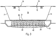
- FIG. 3 One possibility, not according to the invention, for realizing the virtual light sources is shown in Figure 3 shown.
- boards 16 with LEDs 15 are positioned at a distance from the optical element 10 with the lenses 20, the space between the LED boards 16 and the lens optics 10 now being bridged by a cavity 70 which forms a so-called mixing chamber.
- Light emitted by the LEDs 15, which in the case shown are oriented towards the lenses 20, but could also be arranged laterally in the mixing chamber 70, should therefore be reflected as often as possible in this mixing chamber 70 before it passes through the light entry areas 21 in the lens 20 enters and then is discharged to the bottom.
- the mixing chamber 70 is enclosed as completely as possible by reflective, in particular diffusely reflective, walls.
- the side walls 71 of the mixing chamber 70 are inclined, so that the mixing chamber 70 has a trapezoidal shape, in particular in cross section.
- the end faces and rear walls of the mixing chamber 70 are also preferably made of a diffusely reflective material or have a diffusely reflective coating, in which case the surfaces of the boards 16 themselves can also be designed to scatter light. All of these measures are intended to result in the light emitted by the LEDs 15 initially just as in the case of the light guide plate 30 according to FIG Figure 2 is mixed due to multiple reflections before it then enters the lenses 20 via the light entry surfaces 21.
- the occurrence of punctiform high luminous intensities is avoided.
- the light output is not only improved overall as a result, but any differences in the spectral composition of the light output by the LEDs can also be compensated for.
Landscapes
- Physics & Mathematics (AREA)
- General Physics & Mathematics (AREA)
- Optics & Photonics (AREA)
- Engineering & Computer Science (AREA)
- General Engineering & Computer Science (AREA)
- Planar Illumination Modules (AREA)
Description
- Die vorliegende Erfindung betrifft eine Anordnung zur Lichtabgabe, welche eine flächige Anordnung von Linsen aufweist sowie Lichtquellen in Form von LEDs, deren Licht über die Linsen abgegeben wird.
- Der Einsatz von linsenartigen optischen Elementen zur Beeinflussung der Lichtabgabe einer Leuchte ist aus dem Stand der Technik bereits hinlänglich bekannt. Da durch entsprechende Formgebung der Linsen sehr gut Einfluss auf die Verteilung des abgegebenen Lichts genommen werden kann, bieten derartige optische Elemente die Möglichkeit, die Lichtabgabe gezielt in gewünschter Weise anzupassen. Dieser Vorteil kommt insbesondere bei der Verwendung von LEDs als Lichtquellen zum Tragen, da LEDs zunächst Licht in einen sehr breiten Winkelbereich abgeben und dementsprechend eine gezielte Bündelung und Ausrichtung des abgegebenen Lichts unerlässlich ist, um beispielsweise die Anforderungen einer effizienten Beleuchtung eines Arbeitsplatzes oder dergleichen erfüllen zu können.
- Es hat sich dabei in der Vergangenheit eine Ausführungsform als bevorzugt herausgestellt, bei der eine Vielzahl von Linsen zum Einsatz kommt und jeder Linse eine LED individuell zugeordnet ist. Die Linse beeinflusst dann gezielt das Licht der ihr zugeordneten LED. Da in diesem Fall die Linse in definierter Weise bezüglich der LED positioniert wird, kann sichergestellt werden, dass das Licht tatsächlich innerhalb eines gewünschten Winkelbereichs mit der gewünschten Lichtverteilung abgegeben wird. Sowohl die Linsen als auch die LEDs sind dann in der Regel matrixartig angeordnet, wobei die Linsen oftmals zu einem einstückigen optischen Element zusammengefasst sind. Aber auch andere Ausführungsformen gehören zum derzeitigen Stand der Technik.
- So beschreibt
DE 10 2014 200 369 A1 eine sogenannte Flächenleuchtvorrichtung, bei der (LED-)Licht seitlich in einen flächigen Lichtleiter eingekoppelt und über diesen verteilt wird. Die Lichtabgabe in eine Abstrahlrichtung senkrecht zur Lichtleiterplatte erfolgt dann mit Hilfe sogenannter Mikrolinsen, die z. B. Bestandteil einer weiteren Platte sind. Die Lichteintrittsbereiche dieser Linsen sind dabei der Lichtleiterplatte zur Lichtverteilung zugewandt, wobei ein transparenter Haftvermittler vorgesehen ist, welcher einen Eintritt des auszukoppelnden Lichtes von der Lichtleiterplatter in die Linsen ermöglicht. -
JP 2004 227835 A -
US 5 396 350 A offenbart eine Hintergrundbeleuchtungseinrichtung für eine Flachbildschirmanzeige, bestehend aus einer Lichterzeugungseinrichtung sowie einer transparenten Reflexionseinrichtung, wiederum bestehend aus einer ersten Haftvermittlerschicht, einem Substrat, einer zweiten Haftvermittlerschicht und einem asymmetrischen Reflexionsmittel bei einseitiger Lichteinkopplung bzw.
einem symmetrischen Reflexionsmittel bei beidseitiger bzw. vierseitiger Lichteinkopplung in Form von asymmetrischen oder symmetrischen Mikroprismen optional in Kombination mit einer Anordnung von Mikrolinsen. Die Dicke einer dazwischen befindlichen Substratschicht ist so optimiert, dass die Divergenz des an den Mikroprismen divergent reflektierten Lichtes durch die Mikrolinsen geeigneter Brennweite kompensiert wird. -
US 2015/146132 A1 beschreibt eine planare Lichtquellenvorrichtung, mit der flächiges Licht mit Richtwirkung (z. B. zur Hintergrundbeleuchtung) erhalten werden kann. Unter den insgesamt 10 beschriebenen Ausführungsformen offenbart ein eine davon ein plattenförmiges Hohlraumgehäuse, in welches Licht mehrerer Lichtquellen seitlich eingekoppelt, gemischt und gleichverteilt wird. Licht welches eine der in der oberen Platte befindlichen Öffnungen erreicht und das Gehäuse in der Regel divergent verläßt, wird durch unmittelbar über den Öffnungen angeordnete Linsen kollimiert, wodurch es dann im Wesentlichen parallel zur optischen Achse der Linse emittiert wird. -
EP 2 184 628 A2 beschreibt eine Leuchte, z. B. zur Ausleuchtung von Fluchtwegen oder Arbeitsplätzen mit besonderer Gefährdung, in Form einer Kombination aus Lichtquelle (optische Platte) und Piktogramm (Streuscheibe). Die Leuchte besteht also aus einer flachen durchscheinenden Lichtleitplatte, welche auf zumindest einer seitlichen Oberfläche eine Lichtverteilstruktur aufweist, gebildet aus einer Vielzahl von Mikrostrukturen (Mikrolinsen), welche eine gleichmäßige Ausleuchtung der Streuscheibe bewirkt. Das Licht der Lichtleiterplatte wird nahezu ungerichtet der Streuscheibe zugeführt und ebenfalls mittels Mikrostrukturen (in diesem Falle vorteilhafterweise in Form von Prismen) zur Beleuchtung nach außen gestreut. Die Streuscheibe dient insbesondere der Formgebung, der Kontrolle und Verteilung des Lichtes in einem bestimmten Winkelbereich. -
DE 10 2012 215 640 A1 beschreibt eine Lichtleitereinheit für ein Beleuchtungssystem, mit einer Lichtleiterplatte und einer Entblendungseinheit, wobei Lichtquellen seitlich zur Lichtleiterplatte angeordnet sind, sodass seitlich Licht in die Lichtleiterplatte eingekoppelt wird. Die Lichtleiterplatte weist Strukturen zum Auskoppeln von Licht aus der Lichtleiterplatte auf, wobei die Entblendungseinheit mit kollimierende Elemente ausgebildet ist, welche jeweils einer Struktur der Lichtleiterplatte zugeordnet sind. Die Strukturen der Lichtleiterplatte sind hierbei in einer Ausbuchtung des jeweils zugeordneten kollimierenden Elements angeordnet, wobei das kollimierende Element in seinen Abmessungen stets größer ist als die Struktur. - Die oben beschriebenen Ausführungsformen haben sich wie bereits erwähnt vielfach bewährt, es hat sich allerdings gezeigt, dass dennoch gewisse Nachteile hinsichtlich der Lichtabgabe auftreten können. So führt eine individuelle Zuordnung der LEDs zu den Linsen dazu, dass nach wie vor die LEDs als einzelne Lichtquellen erkennbar sind, was in der Regel nicht gewünscht wird. Weiterhin stellen LEDs im Wesentlichen punktförmige Lichtquellen dar, die zu lokal sehr hohen Leuchtstärken führen können. Mit Hilfe der Linsen kann zwar insgesamt die Lichtabgabe auf einen gewünschten Bereich eingeschränkt werden, trotz allem können in diesem Fall dann sehr hohe lokale Leuchtstärken für die Lichtabgabe entstehen, die ebenfalls vermieden werden sollen.
- Der vorliegenden Erfindung liegt deshalb die Aufgabenstellung zugrunde, bei einer Anordnung zur Lichtabgabe, bei der mehrere Linsen sowie LEDs zum Einsatz kommen, die oben beschriebenen Nachteile zu vermeiden.
- Die Aufgabe wird durch eine Anordnung zur Lichtabgabe, welche die Merkmale des Anspruchs 1 aufweist, gelöst. Vorteilhafte Weiterbildungen der Erfindungen sind Gegenstand der abhängigen Ansprüche.
- Die erfindungsgemäße Lösung beruht auf dem Gedanken, von dem Konzept der individuellen Zuordnung einer einzelnen LED zu einer Linse abzuweichen und stattdessen mit Hilfe von Lichtverteilungsmitteln das von mehreren LEDs emittierte Licht zunächst zu verteilen bzw. zu vermischen und anschließend in die jeweiligen Lichteintrittsbereiche der Linsen einzukoppeln. Die Lichtverteilungsmittel dienen in diesem Fall also dazu, den Linsen jeweils individuell zugeordnete virtuelle Lichtquellen zu realisieren, deren Licht dann in gewünschter Weise durch die Linsen beeinflusst wird. Dies führt nicht nur dazu, dass das Auftreten lokaler hoher Leuchtstärken vermieden wird, sondern eröffnet - wie nachfolgend noch näher erläutert - auch die Möglichkeit, das Erscheinungsbild der einzelnen virtuellen Lichtquellen zu variieren.
- Gemäß der vorliegenden Erfindung ist hierbei vorgesehen, dass die erfindungsgemäße Anordnung zur Lichtabgabe eine flächige Anordnung von Linsen aufweist, welche wiederum jeweils einen Lichteintrittsbereich sowie einen Lichtaustrittsbereich aufweisen. Weiterhin enthält die Anordnung Lichtquellen in Form von LEDs, deren Licht über die Linsen abgegeben wird, sowie den Lichteintrittsbereichen der Linsen zugewandte Lichtverteilungsmittel, welche das von den LEDs emittierte Licht verteilen und in die Lichteintrittsbereiche der Linsen einkoppeln.
- Die erfindungsgemäße Anordnung ist dadurch gekennzeichnet, dass die Lichtleiterplatte im Bereich der Lichteintrittsbereiche der Linsen an ihrer Oberfläche Lichtauskoppelstrukturen aufweist, welche auftreffende Lichtstrahlen derart umlenken, dass diese die Lichtleiterplatte verlassen können und in die Linsenkörper eintreten, wobei die Lichtauskoppelstrukturen hinsichtlich ihrer Abmessungen im Wesentlichen den Abmessungen der Lichteintrittsbereiche der Linsen entsprechen. Zudem sind die Lichtauskoppelstrukturen als Aufrauhungen oder Streustrukturen ausgeführt.
- In bekannter Weise können hierbei die LEDs auf einer oder mehreren Platinen angeordnet sein, die dann im Randbereich der Lichtleiterplatte angeordnet sind. Durch Mehrfachreflexionen innerhalb der Lichtleiterplatte wird dann das Licht der LEDs in entsprechender Weise verteilt. Ein Vorteil dieser Vorgehensweise besteht dabei auch darin, dass das Licht der LEDs, bevor es über die Linsen abgegeben wird, zunächst innerhalb der Lichtleiterplatte vermischt wird und dementsprechend geringfügige Abweichungen in der spektralen Zusammensetzung des von den LEDs abgegebenen Lichts ausgeglichen werden können. Insgesamt wird hierdurch also eine homogenere Lichtabgabe hinsichtlich der Farbe bzw. Farbtemperatur erzielt.
- Da in der Regel die LEDs deutlich kleiner sind als der entsprechend zugeordnete Lichteintrittsbereich der Linse besteht also die Möglichkeit, die Abmessung einer virtuellen Lichtquelle exakt an die Abmessung des Lichteintrittsbereichs der zugehörigen Linse anzupassen. Hierdurch wird nicht nur das Auftreten der unerwünschten lokalen hohen Leuchtstärken vermieden sondern die Oberflächenstruktur der Lichtauskoppelstrukturen kann in gezielter Weise beeinflusst werden, um die Lichtabstrahlcharakteristik der erfindungsgemäßen Anordnung weiter zu beeinflussen. Denkbar wäre beispielsweise, Lichtauskoppelstrukturen gezielt durch rillen- oder rasterartige Mikrostrukturen zu realisieren, die einerseits die Lichtauskopplung aus der Lichtleiterplatte ermöglichen, andererseits jedoch bewirken, dass das durch die Linsen abgegebene Licht eine gewisse Strukturierung aufweist.
- Vorzugsweise ist ferner ein Gitter vorgesehen, dessen Öffnungen hinsichtlich ihrer Größe und Positionierung im Wesentlichen den Lichteintrittsbereichen der Linsen entsprechen. Durch diese zusätzliche Maßnahme kann dann verhindert werden, dass Licht abgegeben wird, welches nicht in der gewünschten Weise durch die Linsen beeinflusst wurde. Auch dieses Gitter ist vorzugsweise zur Lichtleiterplatte hin reflektierend ausgebildet, um den Effekt der Lichtdurchmischung zusätzlich zu verstärken.
- Die Linsen selbst können in unterschiedlicher Weise ausgebildet sein, je nachdem in welcher Weise eine Lichtabgabe angestrebt wird. Als vorteilhaft hat sich hierbei insbesondere der Einsatz pyramidenstumpfartiger oder kegelstumpfartiger Linsen herausgestellt, die dann idealerweise matrixartig angeordnet sind. Vorzugsweise sind hierbei die Linsen einstückig zu einem optischen Element zusammengefasst, welches dann das Lichtabgabeelement der Anordnung bildet.
- Letztendlich besteht also mit Hilfe der erfindungsgemäßen Lösung die Möglichkeit, die Lichtabgabe einer Anordnung der eingangs beschriebenen Weise nochmals weiter positiv zu beeinflussen.
- Nachfolgend soll die Erfindung anhand der beiliegenden Zeichnungen näher erläutert werden. Es zeigen:
- Figur 1
- die Schnittdarstellung einer Leuchte, bei der die erfindungsgemäße Anordnung zur flächigen Lichtabgabe zum Einsatz kommt;
- Figur 2
- eine vergrößerte Darstellung des zentralen Bereichs der Leuchte gemäß
Figur 1 , der für die Lichtabgabe verantwortlich ist und eine erfindungsgemäße Anordnung zur flächigen Lichtabgabe aufweist; und - Figur 3
- ein nicht erfindungsgemässes Beispiel des zentralen Bereichs der Leuchte, bei dem die Lichtverteilungsmittel zum Bilden der virtuellen Lichtquellen mit Hilfe einer Lichtkammer realisiert werden.
-
Figur 1 zeigt zunächst ein bevorzugtes Anwendungsbeispiel für die erfindungsgemäße Anordnung zur Lichtabgabe. Dargestellt ist eine allgemein mit dem Bezugszeichen 100 versehene Leuchte, welche eine Weiterentwicklung einer von der Anmelderin unter der Bezeichnung "Mildes Licht" vertriebenen Leuchte darstellt. Im vorliegenden Fall ist die Leuchte 100 als Deckenanbauleuchte ausgeführt, wobei es allerdings selbstverständlich auch ohne weiteres möglich wäre, die Leuchte 100 in vergleichbarer Weise als Deckeneinbauleuchte oder auch als Pendelleuchte zu realisieren. Auch kann das erfindungsgemäße Konzept durchaus bei anderen Leuchten zum Einsatz kommen, bei denen nicht - wie nachfolgend beschrieben - zu beiden Seiten des zentralen Bereichs eine zusätzliche Lichtabgabe erfolgt. - Bei der in
Figur 1 dargestellten Leuchte 100 ist allerdings vorgesehen, dass diese Licht in zwei unterschiedlichen Weisen abgibt. So wird zunächst ein erster Anteil A des Lichts in einem zentralen mittleren Bereich der Leuchte 100 mit verhältnismäßig hoher Intensität abgegeben. Im vorliegenden Fall ist insbesondere eine gerichtete Lichtabgabe zur Unterseite hin vorgesehen, bei der also das Licht innerhalb eines vorgegebenen Winkelbereichs nach unten abgestrahlt wird, um beispielsweise einen Arbeitsplatz, eine Verkaufsfläche oder dergleichen konzentriert zu beleuchten. Für diese gerichtete Lichtabgabe ist die nachfolgend noch näher beschriebene so genannte zentrale "Light Engine" 50 der Leuchte 100 verantwortlich, welche die erfindungsgemäße Anordnung zur flächigen Lichtabgabe beinhaltet. - Zusätzlich ist allerdings bei der Leuchte 100 in
Figur 1 auch vorgesehen, dass über zu beiden Seiten dieser Light Engine 50 angeordnete Bereiche jeweils ein zweiter Lichtanteil B abgegeben wird. Hierzu sind - von dem zu beleuchtenden Bereich aus gesehen - zu beiden Seiten der Light Engine 50 so genannte Lichtkammern 60 ausgebildet, deren Unterseiten jeweils durch flächige, lichtdurchlässige Lichtaustrittselemente 61 abgeschlossen sind. Über diese Lichtaustrittselemente 61 erfolgt die zweite Lichtabgabe B mit einer im Vergleich zur primären Lichtabgabe A deutlich geringeren Intensität, sodass also diese beiden seitlichen Bereiche lediglich leicht aufgehellt werden. Sinn dieser zusätzlichen zweiten Lichtabgabe B ist, dass für einen Beobachter auch unter flacheren Blickwinkeln erkennbar ist, ob die Leuchte 100 aktiviert ist bzw. Licht abgegeben wird. Es ergibt sich hierdurch ein deutlich angenehmeres Erscheinungsbild im Vergleich zu dem Fall, dass ausschließlich eine gerichtete Lichtabgabe über den zentralen Bereich der Light Engine 50 nach unten hin erfolgt, da dieser Bereich unter flachen Winkeln auch im aktivierten Zustand der Leuchte 100 eher dunkel erscheint. Dieses Konzept der zusätzlichen seitlichen Lichtabgabe ist beispielsweise in derDE 100 06 410 der Anmelderin ausführlich beschrieben. - Nachfolgend soll jedoch insbesondere die Ausgestaltung der Light Engine 50 näher erläutert werden, da diese wie bereits erwähnt die erfindungsgemäße Anordnung zur Lichtabgabe beinhaltet.
- Die Ausgestaltung dieser Light Engine 50 kann dabei insbesondere näher der vergrößerten Schnittdarstellung von
Figur 2 entnommen werden. Wie bereits eingangs erwähnt soll hierbei die Beeinflussung des insgesamt abgegebenen Lichts in erster Linie durch eine matrixartige Anordnung von pyramidenstumpfartigen Linsen 20 erfolgen, die an ihrem Lichtaustrittsbereich 22 im dargestellten Ausführungsbeispiel einstückig miteinander verbunden sind und hierdurch ein optisches Element 10 bilden. Das vorzugsweise aus einem klaren Kunststoffmaterial wie zum Beispiel PMMA oder PC gebildete optische Element 10 ist hierbei innerhalb eines profilartigen Trägerteils 40 angeordnet, welches Bestandteil eines Leuchtentragteils 45 ist bzw. mit diesem verbunden ist. Die untere Öffnung 41 des Trägerteils 40 wird durch eine transparente Abdeckscheibe 42 verschlossen, welche allerdings in erster Linie eine Schutzfunktion ausübt und die durch die Linsen 20 vorgenommene Lichtbeeinflussung nicht weiter bzw. zumindest nicht wesentlich beeinflussen soll. - Die einzelnen Linsen 20 sind wie bereits erwähnt etwa pyramidenstumpfartig ausgebildet, könnten allerdings in gleicher Weise auch kegelstumpfartig ausgeführt sein oder komplexere Strukturen aufweisen. Insbesondere sind sie jedoch derart ausgeführt, dass Licht, welches über die Oberseiten 21, die jeweils Lichteintrittsbereiche der Linsen 20 bilden, in den Linsenkörper eintritt, durch Brechung und/oder interne Totalreflexion an den Seitenflächen der Linsen 20 derart beeinflusst wird, dass es an der Unterseite innerhalb eines gewünschten Winkelbereichs abgegeben wird.
- Derartige optische Elemente 10 mit matrixartig angeordneten Linsen 20 waren wie bereits erwähnt aus dem Stand der Technik bereits bekannt, allerdings war hier vorgesehen, jeder Linse 20 individuell eine einzelne LED als Lichtquelle zuzuordnen. Im vorliegenden Fall ist nunmehr erfindungsgemäß vorgesehen, diese individuelle Zuordnung aufzuheben und stattdessen mit Hilfe von Lichtverteilungsmitteln virtuelle Lichtquellen zu erzeugen, welche dann jeweils Licht in die zugehörigen Linsen 20 einstrahlen.
- Diese virtuellen Lichtquellen werden bei dem Ausführungsbeispiel gemäß
Figur 2 dadurch erzeugt, dass eine Lichtleiterplatte 30 zum Einsatz kommt, an deren Unterseite 31, also derjenigen Flachseite, die den Lichteintrittsbereichen 21 der Linsen 20 zugewandt ist, gezielt eine Lichtauskopplung derart erfolgt, dass Licht in die Linsen 20 eintritt. Als Lichtquellen der Anordnung kommen dann LEDs 15 zum Einsatz, die auf länglichen Platinen 16 angeordnet sind, die zu beiden Längsseiten der Lichtleiterplatte 30 positioniert sind, derart, dass die LEDs 15 unmittelbar über die Längsseiten der Lichtleiterplatte 30 Licht in diese einstrahlen. Mit Hilfe von Mehrfachreflexionen wird hierbei dann das Licht innerhalb der Lichtleiterplatte 30 verteilt und damit auch vermischt, wobei dieser Effekt insbesondere dadurch unterstützt werden kann, dass an der der Lichtaustrittsseite 31 der Lichtleiterplatte 30 gegenüberliegenden Rückseite 32 zusätzlich ein Reflektor 17 vorgesehen ist. - Die Lichtauskopplung aus der Lichtleiterplatte 30 in die Linsen 20 erfolgt dann dadurch, dass im Bereich der Lichteintrittsbereiche 21 der Linsen 20 Auskoppelstrukturen 33 (in
Figur 2 sind hierzu lediglich einige der Auskoppelstrukturen 33 schematisch angedeutet) an der Oberfläche der Lichtleiterplatte 30 ausgebildet sind, welche auftreffende Lichtstrahlen derart umlenken, dass diese die Lichtleiterplatte 30 verlassen können und in die Linsenkörper 20 eintreten. Diese Auskoppelstrukturen 33 werden als Aufrauungen oder Streustrukturen ausgeführt. Allerdings wäre es auch denkbar, die entsprechenden Flächenbereiche in gezielter Weise regelmäßig zu strukturieren, um die Art der Lichtabgabe zusätzlich zu beeinflussen. Beispielsweise wäre die Verwendung spezieller Linien oder gitterartiger Strukturen denkbar, welche dann für eine spezielle Art und Weise der Lichtabgabe mit alternierenden Helligkeitsverläufen sorgen. Die Lichtabgabe wird in diesem Fall tatsächlich in erster Linie durch die Struktur der Auskoppelstruktur 33 vorgegeben, da die Linsen 20 hauptsächlich dazu dienen, das mit Hilfe der virtuellen Lichtquelle realisierte Lichtbündel dann auf einen bestimmten Bereich zu beschränken bzw. auf einen bestimmten Bereich zu richten. Wird hingegen eine klassische Aufrauung bzw. statistische Streustruktur verwendet, so wird ein im Wesentlichen homogenes Strahlenbündel erzielt, welches dann durch den pyramidenartigen Linsenkörper 20 auf einen bestimmten Winkelbereich eingeschränkt wird. - Die erfindungsgemäße Lösung gestattet also, durch die Formgebung der Auskoppelstrukturen 33 die Lichtabgabe der gesamten Anordnung zusätzlich zu beeinflussen, sofern dies gewünscht ist. In jedem Fall besteht allerdings die Möglichkeit, die flächenmäßige Größe der Auskoppelstrukturen 33 und damit die Größe der virtuellen Lichtquellen exakt an den Lichteintrittsbereich der jeweils zugehörigen Linse 20 anzupassen. Dies führt nicht nur zu einem verbesserten Erscheinungsbild sondern hat auch zur Folge, dass trotz geringerer maximaler Leuchtdichten aufgrund der größeren Fläche der virtuellen Lichtquellen mit Hilfe der gewünschten Anordnung insgesamt eine hohe Lichtmenge abgegeben werden kann und dementsprechend die Anordnung auch zur Ausleuchtung von Arbeitsplätzen oder anderen Bereichen, in denen hohe Helligkeiten erwünscht oder erforderlich sind, genutzt werden kann.
- Eine weitere Maßnahme zur Verbesserung der Lichtabstrahleigenschaften besteht ferner darin, dass ein Gitter oder Raster 25 zum Einsatz kommt, welches an der Unterseite 31 der Lichtleiterplatte 30 anliegt und derart ausgeführt ist, dass die Gitteröffnungen hinsichtlich ihrer Abmessungen und Dimensionen den Lichteintrittsbereichen 21 der Linsen 20 entsprechen. Das Gitter, dessen der Lichtleiterplatte 30 zugewandte Seite vorzugsweise reflektierend ausgebildet ist, bewirkt dann, dass lediglich solches Licht die gesamte Anordnung verlassen kann, welches auch tatsächlich durch die Linsen 20 beeinflusst wurde. Auch diese Maßnahme trägt dementsprechend zu einer Verbesserung der Lichtabstrahleigenschaften bei.
- Eine, nicht erfindungsgemässe Möglichkeit zur Realisierung der virtuellen Lichtquellen ist in
Figur 3 gezeigt. Hier sind Platinen 16 mit LEDs 15 beabstandet zu dem optischen Element 10 mit den Linsen 20 positioniert, wobei nunmehr der Zwischenraum zwischen den LED-Platinen 16 und der Linsenoptik 10 durch einen Hohlraum 70 überbrückt wird, der eine so genannte Mischkammer bildet. Von den LEDs 15, die im dargestellten Fall auf die Linsen 20 hin ausgerichtet sind, ggf. aber auch seitlich in der Mischkammer 70 angeordnet sein könnten, emittiertes Licht soll in dieser Mischkammer 70 also möglichst oft reflektiert werden, bevor es über die Lichteintrittsbereiche 21 in die Linsen 20 eintritt und dann zur Unterseite hin abgegeben wird. Dies wird dadurch unterstützt, dass die Mischkammer 70 möglichst vollständig von reflektierenden, insbesondere von diffus reflektierenden Wänden umschlossen wird. Im dargestellten Ausführungsbeispiel ist gezeigt, dass die Seitenwände 71 der Mischkammer 70 geneigt verlaufen, sodass sich insbesondere im Querschnitt ein trapezartiger Verlauf der Mischkammer 70 ergibt. Auch Stirnflächen und Rückwände der Mischkammer 70 sind vorzugsweise aus einem diffus reflektierenden Material ausgebildet bzw. weisen eine diffus reflektierende Beschichtung auf, wobei darüber hinaus gegebenenfalls auch die Platinen 16 selbst an ihren Oberflächen lichtstreuend ausgeführt sein können. All diese Maßnahmen sollen dazu führen, dass das von den LEDs 15 emittierte Licht zunächst ebenso wie bei der Lichtleiterplatte 30 gemäßFigur 2 aufgrund vielfacher Reflexionen durchmischt wird, bevor es dann jeweils über die Lichteintrittsflächen 21 in die Linsen 20 eintritt. - Auch in diesem Fall ist wiederum im Bereich der Lichteintrittsflächen 21 der Linsen 20 das bereits anhand von
Figur 2 erläuterte Gitter 25 vorgesehen, welches verhindert, dass in die Zwischenräume zwischen zwei benachbarten Linsen 20 eintretendes Licht die Anordnung verlassen kann. Hier ist von besonderem Vorteil, wenn die der Mischkammer 70 zugewandte Oberfläche des Gitters 25 reflektierend, insbesondere diffus reflektieren ausgeführt ist, um den Effekt der Lichtdurchmischung zusätzlich zu unterstützen. - Auch bei dieser Vorgehensweise werden dann durch das Zusammenwirken von Mischkammer 70 und Gitter 25 virtuelle Lichtquellen realisiert, die dann jeweils Licht in die entsprechende Linse 20 einkoppeln. Der Aufwand zur Realisierung dieser virtuellen Lichtquellen ist im Vergleich zur Nutzung der Lichtleiterplatte etwas geringer, allerdings ist der Platzbedarf etwas größer und es bestehen bei dieser zweiten Ausführungsform dann weniger Möglichkeiten, die Art und Weise der Lichtabgabe der virtuellen Lichtquellen zusätzlich zu beeinflussen. So besteht insbesondere nun nicht die im Zusammenhang mit
Figur 2 erwähnte Möglichkeit, die Lichtauskoppelstrukturen der Lichtleiterplatte in bestimmter Weise zu strukturieren, um hierbei gezielt zusätzlich Einfluss auf die Lichtabgabe zu nehmen. - Letztendlich wird das Auftreten punktueller hoher Leuchtstärken vermieden. Die Lichtabgabe wird hierdurch nicht nur insgesamt verbessert, sondern es können auch eventuelle Unterschiede in den spektralen Zusammensetzungen des von den LEDs abgegebenen Lichts ausgeglichen werden.
Claims (9)
- Anordnung zur Lichtabgabe, aufweisend:• eine flächige Anordnung von Linsen (20), welche jeweils einen Lichteintrittsbereich (21) sowie einen Lichtaustrittsbereich (22) aufweisen,• Lichtquellen in Form von LEDs (15), deren Licht über die Linsen (20) abgegeben wird, sowie• den Lichteintrittsbereichen (21) den Linsen (20) zugewandte Lichtverteilungsmittel, welche das von den LEDs (15) emittierte Licht verteilen und in die Lichteintrittsbereiche (21) der Linsen (20) einkoppeln,wobei die Lichtverteilungsmittel eine Lichtleiterplatte (30) umfassen, welche dazu ausgebildet ist, in die Lichtleiterplatte (30) eingekoppeltes Licht zu verteilen und über eine den Linsen (20) zugewandte Flachseite (31) abzugeben,
wobei die Lichtleiterplatte (30) im Bereich der Lichteintrittsbereiche (21) der Linsen (20) an ihrer Oberfläche (31) Lichtauskoppelstrukturen (33) aufweist, welche auftreffende Lichtstrahlen derart umlenken, dass diese die Lichtleiterplatte (30) verlassen können und in die Linsenkörper (20) eintreten,
wobei die Lichtauskoppelstrukturen (33) hinsichtlich ihrer Abmessungen im Wesentlichen den Abmessungen der Lichteintrittsbereiche (21) der Linsen (20) entsprechen, dadurch gekennzeichnet, dass die Lichtauskoppelstrukturen (33) als Aufrauhungen oder Streustrukturen ausgeführt sind. - Anordnung zur Lichtabgabe nach Anspruch 1,
dadurch gekennzeichnet,
dass die LEDs (15) auf einer oder mehreren Platinen (16) angeordnet sind, welche im Randbereich der Lichtleiterplatte (30) angeordnet sind. - Anordnung zur Lichtabgabe nach Anspruch 1 oder 2,
dadurch gekennzeichnet,
dass die LEDs (15) an zumindest einem Randbereich der Lichtleiterplatte (30), vorzugsweise an zwei einander gegenüberliegenden Randbereichen der Lichtleiterplatte (30) angeordnet sind. - Anordnung nach einem der Ansprüche 1 bis 3,
dadurch gekennzeichnet,
dass die Lichtauskoppelstrukturen (33) eine regelmäßige Struktur, insbesondere eine Gitterstruktur oder eine Rillenstruktur aufweisen. - Anordnung zur Lichtabgabe nach einem der vorherigen Ansprüche,
dadurch gekennzeichnet,
dass diese ferner ein Gitter (25) aufweist, dessen Öffnungen hinsichtlich ihrer Größe und Positionierung im Wesentlichen den Lichteintrittsbereichen (21) der Linsen (20) entsprechen. - Anordnung zur Lichtabgabe nach einem der vorherigen Ansprüche,
dadurch gekennzeichnet,
dass die Linsen (20) pyramidenstumpfartig oder kegelstumpfartig ausgebildet sind. - Anordnung zur Lichtabgabe nach einem der vorherigen Ansprüche,
dadurch gekennzeichnet,
dass die Linsen (20) matrixartig angeordnet sind. - Anordnung zur Lichtabgabe nach Anspruch 7,
dadurch gekennzeichnet,
dass die Linsen (20) einstückig zu einem optischen Element (10) zusammengefasst sind. - Leuchte mit einer Anordnung zur Lichtabgabe nach einem der vorherigen Ansprüche.
Applications Claiming Priority (3)
| Application Number | Priority Date | Filing Date | Title |
|---|---|---|---|
| DE102015219600 | 2015-10-09 | ||
| DE102016207137.8A DE102016207137A1 (de) | 2015-10-09 | 2016-04-27 | Anordnung zur Lichtabgabe |
| PCT/EP2016/074083 WO2017060479A1 (de) | 2015-10-09 | 2016-10-07 | Anordnung zur lichtabgabe |
Publications (2)
| Publication Number | Publication Date |
|---|---|
| EP3359874A1 EP3359874A1 (de) | 2018-08-15 |
| EP3359874B1 true EP3359874B1 (de) | 2020-12-09 |
Family
ID=58405897
Family Applications (1)
| Application Number | Title | Priority Date | Filing Date |
|---|---|---|---|
| EP16778064.2A Active EP3359874B1 (de) | 2015-10-09 | 2016-10-07 | Anordnung zur lichtabgabe |
Country Status (4)
| Country | Link |
|---|---|
| EP (1) | EP3359874B1 (de) |
| AT (2) | AT16410U1 (de) |
| DE (1) | DE102016207137A1 (de) |
| WO (1) | WO2017060479A1 (de) |
Citations (1)
| Publication number | Priority date | Publication date | Assignee | Title |
|---|---|---|---|---|
| DE102012215640A1 (de) * | 2012-09-04 | 2014-03-06 | Zumtobel Lighting Gmbh | Lichtleitereinheit für ein Beleuchtungssystem |
Family Cites Families (19)
| Publication number | Priority date | Publication date | Assignee | Title |
|---|---|---|---|---|
| DE10006410A1 (de) | 2000-02-14 | 2001-08-16 | Zumtobel Staff Gmbh | Leuchte |
| US5396350A (en) * | 1993-11-05 | 1995-03-07 | Alliedsignal Inc. | Backlighting apparatus employing an array of microprisms |
| US5428468A (en) * | 1993-11-05 | 1995-06-27 | Alliedsignal Inc. | Illumination system employing an array of microprisms |
| US6185357B1 (en) * | 1998-09-10 | 2001-02-06 | Honeywell International Inc. | Illumination system using edge-illuminated hollow waveguide and lenticular optical structures |
| EP1065436B1 (de) * | 1999-05-28 | 2007-04-04 | Siteco Beleuchtungstechnik GmbH | Deckenleuchte mit Lichtleiter |
| JP2004227835A (ja) * | 2003-01-21 | 2004-08-12 | Konica Minolta Holdings Inc | 照明装置および液晶表示装置 |
| US20050185416A1 (en) * | 2004-02-24 | 2005-08-25 | Eastman Kodak Company | Brightness enhancement film using light concentrator array |
| US7249869B2 (en) * | 2004-07-30 | 2007-07-31 | Toyoda Gosei Co., Ltd. | Light emitting device |
| US20080158476A1 (en) * | 2006-12-06 | 2008-07-03 | Citizen Electronics Co., Ltd. | Optical member, backlight unit and display apparatus having the same |
| DE102008014317A1 (de) * | 2008-03-14 | 2009-09-17 | Zumtobel Lighting Gmbh | Leuchte mit getrennten Leuchtmitteln für Direktbeleuchtung und Indirektbeleuchtung |
| EP2184628A3 (de) * | 2008-11-06 | 2010-10-06 | CEAG Notlichtsysteme GmbH | Leuchte, insbesondere Not-, Rettungs oder Sicherheitsleuchte |
| CN102472862A (zh) * | 2009-07-10 | 2012-05-23 | 皇家飞利浦电子股份有限公司 | 自由形式的发光模块 |
| WO2011033424A1 (en) * | 2009-09-21 | 2011-03-24 | Koninklijke Philips Electronics N.V. | Light emitting device comprising a light guide plate with reflective shielding with glare reduction |
| KR101441894B1 (ko) * | 2010-08-18 | 2014-09-19 | 주식회사 뷰라이팅인터내셔널 | 엘이디 확산렌즈 |
| KR20120044195A (ko) * | 2010-10-27 | 2012-05-07 | 엘지디스플레이 주식회사 | 액정표시장치 |
| WO2013046081A1 (en) * | 2011-09-27 | 2013-04-04 | Koninklijke Philips Electronics N.V. | A lighting system for emitting a shaped light beam and a luminaire |
| JP2013254649A (ja) * | 2012-06-07 | 2013-12-19 | Sharp Corp | 面光源装置、表示装置および照明装置 |
| WO2015082575A1 (en) * | 2013-12-05 | 2015-06-11 | Koninklijke Philips N.V. | Optical device, lighting device and lighting system |
| DE102014200369A1 (de) * | 2014-01-10 | 2015-07-16 | Osram Gmbh | Flächenleuchtvorrichtung mit flächigem Lichtleiter |
-
2015
- 2015-12-22 AT ATGM386/2015U patent/AT16410U1/de not_active IP Right Cessation
-
2016
- 2016-04-27 DE DE102016207137.8A patent/DE102016207137A1/de not_active Withdrawn
- 2016-06-21 AT ATGM151/2016U patent/AT15384U1/de not_active IP Right Cessation
- 2016-10-07 WO PCT/EP2016/074083 patent/WO2017060479A1/de not_active Ceased
- 2016-10-07 EP EP16778064.2A patent/EP3359874B1/de active Active
Patent Citations (1)
| Publication number | Priority date | Publication date | Assignee | Title |
|---|---|---|---|---|
| DE102012215640A1 (de) * | 2012-09-04 | 2014-03-06 | Zumtobel Lighting Gmbh | Lichtleitereinheit für ein Beleuchtungssystem |
Also Published As
| Publication number | Publication date |
|---|---|
| AT16410U1 (de) | 2019-08-15 |
| DE102016207137A1 (de) | 2017-04-13 |
| WO2017060479A1 (de) | 2017-04-13 |
| EP3359874A1 (de) | 2018-08-15 |
| AT15384U1 (de) | 2017-07-15 |
Similar Documents
| Publication | Publication Date | Title |
|---|---|---|
| EP2281143B1 (de) | Leuchte mit getrennten leuchtmitteln für direktbeleuchtung und indirektbeleuchtung | |
| EP2726779B1 (de) | Anordnung zur lichtabgabe mit punktförmigen lichtquellen und lichtlenkungselement | |
| AT16685U1 (de) | Direktstrahlende LED-Leuchte mit Entblendungsoptik | |
| DE102004002251A1 (de) | Leuchte mit verschiedenfarbigen Lichtquellen sowie einer Lichtleiterplatte zum Abgeben von Mischlicht | |
| DE102012111313B4 (de) | Beleuchtungseinheit für ein Kraftfahrzeug | |
| DE102004046256A1 (de) | Oberflächenleuchtsystem | |
| EP2587134A1 (de) | Leuchte | |
| EP3092439A2 (de) | Leuchtvorrichtung | |
| EP2982903B1 (de) | Leuchtenanordnung und damit ausgestattete leuchtvorrichtung | |
| EP3359874B1 (de) | Anordnung zur lichtabgabe | |
| EP2642470B1 (de) | Plattenförmiges Lichtleitelement und Leuchte mit Lichtleitelement | |
| EP3408587B1 (de) | Optisches system zum beeinflussen der lichtabgabe einer lichtquelle | |
| EP3869093B1 (de) | Flächenleuchte mit direkter und indirekter lichtabgabe | |
| EP2924343B1 (de) | Led-leuchte mit refraktiver optik zur lichtdurchmischung | |
| EP3591281B1 (de) | Innenraumleuchte | |
| EP4168711B1 (de) | Anordnung zur lichtabgabe und leuchte | |
| DE202005001507U1 (de) | Oberflächenleuchtsystem | |
| EP3329178B1 (de) | Lichtleiterelement | |
| EP3358250B1 (de) | Leuchte mit einer lichtleitplatte mit umlenkstrukturen | |
| DE202024104176U1 (de) | Modulares System zum Bilden einer Leuchte | |
| EP2487409A1 (de) | Reflektor für Beleuchtungszwecke | |
| EP3270048A1 (de) | Leuchte mit durchgangsöffnungen | |
| DE102013224597A1 (de) | Optischer Strahler |
Legal Events
| Date | Code | Title | Description |
|---|---|---|---|
| STAA | Information on the status of an ep patent application or granted ep patent |
Free format text: STATUS: THE INTERNATIONAL PUBLICATION HAS BEEN MADE |
|
| PUAI | Public reference made under article 153(3) epc to a published international application that has entered the european phase |
Free format text: ORIGINAL CODE: 0009012 |
|
| STAA | Information on the status of an ep patent application or granted ep patent |
Free format text: STATUS: REQUEST FOR EXAMINATION WAS MADE |
|
| 17P | Request for examination filed |
Effective date: 20180327 |
|
| AK | Designated contracting states |
Kind code of ref document: A1 Designated state(s): AL AT BE BG CH CY CZ DE DK EE ES FI FR GB GR HR HU IE IS IT LI LT LU LV MC MK MT NL NO PL PT RO RS SE SI SK SM TR |
|
| AX | Request for extension of the european patent |
Extension state: BA ME |
|
| RIN1 | Information on inventor provided before grant (corrected) |
Inventor name: NIEDERSTAETTER, ANDREAS Inventor name: CERV, SIMON Inventor name: FRICK, JOACHIM Inventor name: REIN, THOMAS Inventor name: SCHWAIGHOFER, ANDREAS |
|
| RIN1 | Information on inventor provided before grant (corrected) |
Inventor name: NIEDERSTAETTER, ANDREAS Inventor name: SCHWAIGHOFER, ANDREAS Inventor name: FRICK, JOACHIM Inventor name: CERV, SIMON Inventor name: REIN, THOMAS |
|
| DAV | Request for validation of the european patent (deleted) | ||
| DAX | Request for extension of the european patent (deleted) | ||
| STAA | Information on the status of an ep patent application or granted ep patent |
Free format text: STATUS: EXAMINATION IS IN PROGRESS |
|
| 17Q | First examination report despatched |
Effective date: 20191126 |
|
| GRAP | Despatch of communication of intention to grant a patent |
Free format text: ORIGINAL CODE: EPIDOSNIGR1 |
|
| STAA | Information on the status of an ep patent application or granted ep patent |
Free format text: STATUS: GRANT OF PATENT IS INTENDED |
|
| INTG | Intention to grant announced |
Effective date: 20200828 |
|
| GRAS | Grant fee paid |
Free format text: ORIGINAL CODE: EPIDOSNIGR3 |
|
| GRAA | (expected) grant |
Free format text: ORIGINAL CODE: 0009210 |
|
| STAA | Information on the status of an ep patent application or granted ep patent |
Free format text: STATUS: THE PATENT HAS BEEN GRANTED |
|
| AK | Designated contracting states |
Kind code of ref document: B1 Designated state(s): AL AT BE BG CH CY CZ DE DK EE ES FI FR GB GR HR HU IE IS IT LI LT LU LV MC MK MT NL NO PL PT RO RS SE SI SK SM TR |
|
| REG | Reference to a national code |
Ref country code: GB Ref legal event code: FG4D Free format text: NOT ENGLISH |
|
| REG | Reference to a national code |
Ref country code: AT Ref legal event code: REF Ref document number: 1343826 Country of ref document: AT Kind code of ref document: T Effective date: 20201215 Ref country code: CH Ref legal event code: EP |
|
| REG | Reference to a national code |
Ref country code: DE Ref legal event code: R096 Ref document number: 502016011942 Country of ref document: DE |
|
| REG | Reference to a national code |
Ref country code: IE Ref legal event code: FG4D Free format text: LANGUAGE OF EP DOCUMENT: GERMAN |
|
| PG25 | Lapsed in a contracting state [announced via postgrant information from national office to epo] |
Ref country code: FI Free format text: LAPSE BECAUSE OF FAILURE TO SUBMIT A TRANSLATION OF THE DESCRIPTION OR TO PAY THE FEE WITHIN THE PRESCRIBED TIME-LIMIT Effective date: 20201209 Ref country code: GR Free format text: LAPSE BECAUSE OF FAILURE TO SUBMIT A TRANSLATION OF THE DESCRIPTION OR TO PAY THE FEE WITHIN THE PRESCRIBED TIME-LIMIT Effective date: 20210310 Ref country code: RS Free format text: LAPSE BECAUSE OF FAILURE TO SUBMIT A TRANSLATION OF THE DESCRIPTION OR TO PAY THE FEE WITHIN THE PRESCRIBED TIME-LIMIT Effective date: 20201209 Ref country code: NO Free format text: LAPSE BECAUSE OF FAILURE TO SUBMIT A TRANSLATION OF THE DESCRIPTION OR TO PAY THE FEE WITHIN THE PRESCRIBED TIME-LIMIT Effective date: 20210309 |
|
| PG25 | Lapsed in a contracting state [announced via postgrant information from national office to epo] |
Ref country code: SE Free format text: LAPSE BECAUSE OF FAILURE TO SUBMIT A TRANSLATION OF THE DESCRIPTION OR TO PAY THE FEE WITHIN THE PRESCRIBED TIME-LIMIT Effective date: 20201209 Ref country code: BG Free format text: LAPSE BECAUSE OF FAILURE TO SUBMIT A TRANSLATION OF THE DESCRIPTION OR TO PAY THE FEE WITHIN THE PRESCRIBED TIME-LIMIT Effective date: 20210309 Ref country code: LV Free format text: LAPSE BECAUSE OF FAILURE TO SUBMIT A TRANSLATION OF THE DESCRIPTION OR TO PAY THE FEE WITHIN THE PRESCRIBED TIME-LIMIT Effective date: 20201209 |
|
| REG | Reference to a national code |
Ref country code: NL Ref legal event code: MP Effective date: 20201209 |
|
| PG25 | Lapsed in a contracting state [announced via postgrant information from national office to epo] |
Ref country code: NL Free format text: LAPSE BECAUSE OF FAILURE TO SUBMIT A TRANSLATION OF THE DESCRIPTION OR TO PAY THE FEE WITHIN THE PRESCRIBED TIME-LIMIT Effective date: 20201209 Ref country code: HR Free format text: LAPSE BECAUSE OF FAILURE TO SUBMIT A TRANSLATION OF THE DESCRIPTION OR TO PAY THE FEE WITHIN THE PRESCRIBED TIME-LIMIT Effective date: 20201209 |
|
| REG | Reference to a national code |
Ref country code: LT Ref legal event code: MG9D |
|
| PG25 | Lapsed in a contracting state [announced via postgrant information from national office to epo] |
Ref country code: PT Free format text: LAPSE BECAUSE OF FAILURE TO SUBMIT A TRANSLATION OF THE DESCRIPTION OR TO PAY THE FEE WITHIN THE PRESCRIBED TIME-LIMIT Effective date: 20210409 Ref country code: RO Free format text: LAPSE BECAUSE OF FAILURE TO SUBMIT A TRANSLATION OF THE DESCRIPTION OR TO PAY THE FEE WITHIN THE PRESCRIBED TIME-LIMIT Effective date: 20201209 Ref country code: SK Free format text: LAPSE BECAUSE OF FAILURE TO SUBMIT A TRANSLATION OF THE DESCRIPTION OR TO PAY THE FEE WITHIN THE PRESCRIBED TIME-LIMIT Effective date: 20201209 Ref country code: SM Free format text: LAPSE BECAUSE OF FAILURE TO SUBMIT A TRANSLATION OF THE DESCRIPTION OR TO PAY THE FEE WITHIN THE PRESCRIBED TIME-LIMIT Effective date: 20201209 Ref country code: LT Free format text: LAPSE BECAUSE OF FAILURE TO SUBMIT A TRANSLATION OF THE DESCRIPTION OR TO PAY THE FEE WITHIN THE PRESCRIBED TIME-LIMIT Effective date: 20201209 Ref country code: CZ Free format text: LAPSE BECAUSE OF FAILURE TO SUBMIT A TRANSLATION OF THE DESCRIPTION OR TO PAY THE FEE WITHIN THE PRESCRIBED TIME-LIMIT Effective date: 20201209 Ref country code: EE Free format text: LAPSE BECAUSE OF FAILURE TO SUBMIT A TRANSLATION OF THE DESCRIPTION OR TO PAY THE FEE WITHIN THE PRESCRIBED TIME-LIMIT Effective date: 20201209 |
|
| PG25 | Lapsed in a contracting state [announced via postgrant information from national office to epo] |
Ref country code: PL Free format text: LAPSE BECAUSE OF FAILURE TO SUBMIT A TRANSLATION OF THE DESCRIPTION OR TO PAY THE FEE WITHIN THE PRESCRIBED TIME-LIMIT Effective date: 20201209 |
|
| REG | Reference to a national code |
Ref country code: DE Ref legal event code: R097 Ref document number: 502016011942 Country of ref document: DE |
|
| PG25 | Lapsed in a contracting state [announced via postgrant information from national office to epo] |
Ref country code: IS Free format text: LAPSE BECAUSE OF FAILURE TO SUBMIT A TRANSLATION OF THE DESCRIPTION OR TO PAY THE FEE WITHIN THE PRESCRIBED TIME-LIMIT Effective date: 20210409 |
|
| PLBE | No opposition filed within time limit |
Free format text: ORIGINAL CODE: 0009261 |
|
| STAA | Information on the status of an ep patent application or granted ep patent |
Free format text: STATUS: NO OPPOSITION FILED WITHIN TIME LIMIT |
|
| PG25 | Lapsed in a contracting state [announced via postgrant information from national office to epo] |
Ref country code: AL Free format text: LAPSE BECAUSE OF FAILURE TO SUBMIT A TRANSLATION OF THE DESCRIPTION OR TO PAY THE FEE WITHIN THE PRESCRIBED TIME-LIMIT Effective date: 20201209 Ref country code: IT Free format text: LAPSE BECAUSE OF FAILURE TO SUBMIT A TRANSLATION OF THE DESCRIPTION OR TO PAY THE FEE WITHIN THE PRESCRIBED TIME-LIMIT Effective date: 20201209 |
|
| 26N | No opposition filed |
Effective date: 20210910 |
|
| PG25 | Lapsed in a contracting state [announced via postgrant information from national office to epo] |
Ref country code: DK Free format text: LAPSE BECAUSE OF FAILURE TO SUBMIT A TRANSLATION OF THE DESCRIPTION OR TO PAY THE FEE WITHIN THE PRESCRIBED TIME-LIMIT Effective date: 20201209 Ref country code: SI Free format text: LAPSE BECAUSE OF FAILURE TO SUBMIT A TRANSLATION OF THE DESCRIPTION OR TO PAY THE FEE WITHIN THE PRESCRIBED TIME-LIMIT Effective date: 20201209 |
|
| PG25 | Lapsed in a contracting state [announced via postgrant information from national office to epo] |
Ref country code: ES Free format text: LAPSE BECAUSE OF FAILURE TO SUBMIT A TRANSLATION OF THE DESCRIPTION OR TO PAY THE FEE WITHIN THE PRESCRIBED TIME-LIMIT Effective date: 20201209 |
|
| REG | Reference to a national code |
Ref country code: CH Ref legal event code: PL |
|
| PG25 | Lapsed in a contracting state [announced via postgrant information from national office to epo] |
Ref country code: IS Free format text: LAPSE BECAUSE OF FAILURE TO SUBMIT A TRANSLATION OF THE DESCRIPTION OR TO PAY THE FEE WITHIN THE PRESCRIBED TIME-LIMIT Effective date: 20210409 |
|
| REG | Reference to a national code |
Ref country code: BE Ref legal event code: MM Effective date: 20211031 |
|
| PG25 | Lapsed in a contracting state [announced via postgrant information from national office to epo] |
Ref country code: MC Free format text: LAPSE BECAUSE OF FAILURE TO SUBMIT A TRANSLATION OF THE DESCRIPTION OR TO PAY THE FEE WITHIN THE PRESCRIBED TIME-LIMIT Effective date: 20201209 |
|
| PG25 | Lapsed in a contracting state [announced via postgrant information from national office to epo] |
Ref country code: LU Free format text: LAPSE BECAUSE OF NON-PAYMENT OF DUE FEES Effective date: 20211007 Ref country code: BE Free format text: LAPSE BECAUSE OF NON-PAYMENT OF DUE FEES Effective date: 20211031 |
|
| PG25 | Lapsed in a contracting state [announced via postgrant information from national office to epo] |
Ref country code: LI Free format text: LAPSE BECAUSE OF NON-PAYMENT OF DUE FEES Effective date: 20211031 Ref country code: CH Free format text: LAPSE BECAUSE OF NON-PAYMENT OF DUE FEES Effective date: 20211031 |
|
| PG25 | Lapsed in a contracting state [announced via postgrant information from national office to epo] |
Ref country code: IE Free format text: LAPSE BECAUSE OF NON-PAYMENT OF DUE FEES Effective date: 20211007 |
|
| REG | Reference to a national code |
Ref country code: AT Ref legal event code: MM01 Ref document number: 1343826 Country of ref document: AT Kind code of ref document: T Effective date: 20211007 |
|
| PGFP | Annual fee paid to national office [announced via postgrant information from national office to epo] |
Ref country code: FR Payment date: 20221024 Year of fee payment: 7 |
|
| PG25 | Lapsed in a contracting state [announced via postgrant information from national office to epo] |
Ref country code: AT Free format text: LAPSE BECAUSE OF NON-PAYMENT OF DUE FEES Effective date: 20211007 |
|
| PG25 | Lapsed in a contracting state [announced via postgrant information from national office to epo] |
Ref country code: HU Free format text: LAPSE BECAUSE OF FAILURE TO SUBMIT A TRANSLATION OF THE DESCRIPTION OR TO PAY THE FEE WITHIN THE PRESCRIBED TIME-LIMIT; INVALID AB INITIO Effective date: 20161007 |
|
| PG25 | Lapsed in a contracting state [announced via postgrant information from national office to epo] |
Ref country code: CY Free format text: LAPSE BECAUSE OF FAILURE TO SUBMIT A TRANSLATION OF THE DESCRIPTION OR TO PAY THE FEE WITHIN THE PRESCRIBED TIME-LIMIT Effective date: 20201209 |
|
| P01 | Opt-out of the competence of the unified patent court (upc) registered |
Effective date: 20230530 |
|
| REG | Reference to a national code |
Ref country code: DE Ref legal event code: R084 Ref document number: 502016011942 Country of ref document: DE |
|
| PG25 | Lapsed in a contracting state [announced via postgrant information from national office to epo] |
Ref country code: MK Free format text: LAPSE BECAUSE OF FAILURE TO SUBMIT A TRANSLATION OF THE DESCRIPTION OR TO PAY THE FEE WITHIN THE PRESCRIBED TIME-LIMIT Effective date: 20201209 |
|
| PG25 | Lapsed in a contracting state [announced via postgrant information from national office to epo] |
Ref country code: TR Free format text: LAPSE BECAUSE OF FAILURE TO SUBMIT A TRANSLATION OF THE DESCRIPTION OR TO PAY THE FEE WITHIN THE PRESCRIBED TIME-LIMIT Effective date: 20201209 |
|
| PG25 | Lapsed in a contracting state [announced via postgrant information from national office to epo] |
Ref country code: FR Free format text: LAPSE BECAUSE OF NON-PAYMENT OF DUE FEES Effective date: 20231031 |
|
| PG25 | Lapsed in a contracting state [announced via postgrant information from national office to epo] |
Ref country code: MT Free format text: LAPSE BECAUSE OF FAILURE TO SUBMIT A TRANSLATION OF THE DESCRIPTION OR TO PAY THE FEE WITHIN THE PRESCRIBED TIME-LIMIT Effective date: 20201209 |
|
| PGFP | Annual fee paid to national office [announced via postgrant information from national office to epo] |
Ref country code: GB Payment date: 20241023 Year of fee payment: 9 |
|
| PGFP | Annual fee paid to national office [announced via postgrant information from national office to epo] |
Ref country code: DE Payment date: 20251028 Year of fee payment: 10 |