EP3360782B1 - Soupape énergétique de terminaison séquencielle à usage unique - Google Patents
Soupape énergétique de terminaison séquencielle à usage unique Download PDFInfo
- Publication number
- EP3360782B1 EP3360782B1 EP18155869.3A EP18155869A EP3360782B1 EP 3360782 B1 EP3360782 B1 EP 3360782B1 EP 18155869 A EP18155869 A EP 18155869A EP 3360782 B1 EP3360782 B1 EP 3360782B1
- Authority
- EP
- European Patent Office
- Prior art keywords
- energetic
- inlet
- signal
- response
- outlet
- Prior art date
- Legal status (The legal status is an assumption and is not a legal conclusion. Google has not performed a legal analysis and makes no representation as to the accuracy of the status listed.)
- Active
Links
Images


Classifications
-
- F—MECHANICAL ENGINEERING; LIGHTING; HEATING; WEAPONS; BLASTING
- F16—ENGINEERING ELEMENTS AND UNITS; GENERAL MEASURES FOR PRODUCING AND MAINTAINING EFFECTIVE FUNCTIONING OF MACHINES OR INSTALLATIONS; THERMAL INSULATION IN GENERAL
- F16K—VALVES; TAPS; COCKS; ACTUATING-FLOATS; DEVICES FOR VENTING OR AERATING
- F16K11/00—Multiple-way valves, e.g. mixing valves; Pipe fittings incorporating such valves
- F16K11/10—Multiple-way valves, e.g. mixing valves; Pipe fittings incorporating such valves with two or more closure members not moving as a unit
- F16K11/20—Multiple-way valves, e.g. mixing valves; Pipe fittings incorporating such valves with two or more closure members not moving as a unit operated by separate actuating members
- F16K11/22—Multiple-way valves, e.g. mixing valves; Pipe fittings incorporating such valves with two or more closure members not moving as a unit operated by separate actuating members with an actuating member for each valve, e.g. interconnected to form multiple-way valves
-
- B—PERFORMING OPERATIONS; TRANSPORTING
- B64—AIRCRAFT; AVIATION; COSMONAUTICS
- B64D—EQUIPMENT FOR FITTING IN OR TO AIRCRAFT; FLIGHT SUITS; PARACHUTES; ARRANGEMENT OR MOUNTING OF POWER PLANTS OR PROPULSION TRANSMISSIONS IN AIRCRAFT
- B64D25/00—Emergency apparatus or devices, not otherwise provided for
-
- F—MECHANICAL ENGINEERING; LIGHTING; HEATING; WEAPONS; BLASTING
- F15—FLUID-PRESSURE ACTUATORS; HYDRAULICS OR PNEUMATICS IN GENERAL
- F15B—SYSTEMS ACTING BY MEANS OF FLUIDS IN GENERAL; FLUID-PRESSURE ACTUATORS, e.g. SERVOMOTORS; DETAILS OF FLUID-PRESSURE SYSTEMS, NOT OTHERWISE PROVIDED FOR
- F15B13/00—Details of servomotor systems ; Valves for servomotor systems
- F15B13/02—Fluid distribution or supply devices characterised by their adaptation to the control of servomotors
- F15B13/028—Shuttle valves
-
- F—MECHANICAL ENGINEERING; LIGHTING; HEATING; WEAPONS; BLASTING
- F15—FLUID-PRESSURE ACTUATORS; HYDRAULICS OR PNEUMATICS IN GENERAL
- F15B—SYSTEMS ACTING BY MEANS OF FLUIDS IN GENERAL; FLUID-PRESSURE ACTUATORS, e.g. SERVOMOTORS; DETAILS OF FLUID-PRESSURE SYSTEMS, NOT OTHERWISE PROVIDED FOR
- F15B13/00—Details of servomotor systems ; Valves for servomotor systems
- F15B13/02—Fluid distribution or supply devices characterised by their adaptation to the control of servomotors
- F15B13/04—Fluid distribution or supply devices characterised by their adaptation to the control of servomotors for use with a single servomotor
- F15B13/0401—Valve members; Fluid interconnections therefor
- F15B13/0402—Valve members; Fluid interconnections therefor for linearly sliding valves, e.g. spool valves
-
- F—MECHANICAL ENGINEERING; LIGHTING; HEATING; WEAPONS; BLASTING
- F16—ENGINEERING ELEMENTS AND UNITS; GENERAL MEASURES FOR PRODUCING AND MAINTAINING EFFECTIVE FUNCTIONING OF MACHINES OR INSTALLATIONS; THERMAL INSULATION IN GENERAL
- F16K—VALVES; TAPS; COCKS; ACTUATING-FLOATS; DEVICES FOR VENTING OR AERATING
- F16K11/00—Multiple-way valves, e.g. mixing valves; Pipe fittings incorporating such valves
- F16K11/02—Multiple-way valves, e.g. mixing valves; Pipe fittings incorporating such valves with all movable sealing faces moving as one unit
- F16K11/06—Multiple-way valves, e.g. mixing valves; Pipe fittings incorporating such valves with all movable sealing faces moving as one unit comprising only sliding valves, i.e. sliding closure elements
- F16K11/065—Multiple-way valves, e.g. mixing valves; Pipe fittings incorporating such valves with all movable sealing faces moving as one unit comprising only sliding valves, i.e. sliding closure elements with linearly sliding closure members
- F16K11/0655—Multiple-way valves, e.g. mixing valves; Pipe fittings incorporating such valves with all movable sealing faces moving as one unit comprising only sliding valves, i.e. sliding closure elements with linearly sliding closure members with flat slides
-
- F—MECHANICAL ENGINEERING; LIGHTING; HEATING; WEAPONS; BLASTING
- F16—ENGINEERING ELEMENTS AND UNITS; GENERAL MEASURES FOR PRODUCING AND MAINTAINING EFFECTIVE FUNCTIONING OF MACHINES OR INSTALLATIONS; THERMAL INSULATION IN GENERAL
- F16K—VALVES; TAPS; COCKS; ACTUATING-FLOATS; DEVICES FOR VENTING OR AERATING
- F16K17/00—Safety valves; Equalising valves, e.g. pressure relief valves
- F16K17/003—Safety valves; Equalising valves, e.g. pressure relief valves reacting to pressure and temperature
-
- F—MECHANICAL ENGINEERING; LIGHTING; HEATING; WEAPONS; BLASTING
- F16—ENGINEERING ELEMENTS AND UNITS; GENERAL MEASURES FOR PRODUCING AND MAINTAINING EFFECTIVE FUNCTIONING OF MACHINES OR INSTALLATIONS; THERMAL INSULATION IN GENERAL
- F16K—VALVES; TAPS; COCKS; ACTUATING-FLOATS; DEVICES FOR VENTING OR AERATING
- F16K17/00—Safety valves; Equalising valves, e.g. pressure relief valves
- F16K17/20—Excess-flow valves
- F16K17/34—Excess-flow valves in which the flow-energy of the flowing medium actuates the closing mechanism
-
- F—MECHANICAL ENGINEERING; LIGHTING; HEATING; WEAPONS; BLASTING
- F16—ENGINEERING ELEMENTS AND UNITS; GENERAL MEASURES FOR PRODUCING AND MAINTAINING EFFECTIVE FUNCTIONING OF MACHINES OR INSTALLATIONS; THERMAL INSULATION IN GENERAL
- F16K—VALVES; TAPS; COCKS; ACTUATING-FLOATS; DEVICES FOR VENTING OR AERATING
- F16K31/00—Actuating devices; Operating means; Releasing devices
- F16K31/12—Actuating devices; Operating means; Releasing devices actuated by fluid
- F16K31/122—Actuating devices; Operating means; Releasing devices actuated by fluid the fluid acting on a piston
- F16K31/1223—Actuating devices; Operating means; Releasing devices actuated by fluid the fluid acting on a piston one side of the piston being acted upon by the circulating fluid
-
- F—MECHANICAL ENGINEERING; LIGHTING; HEATING; WEAPONS; BLASTING
- F15—FLUID-PRESSURE ACTUATORS; HYDRAULICS OR PNEUMATICS IN GENERAL
- F15B—SYSTEMS ACTING BY MEANS OF FLUIDS IN GENERAL; FLUID-PRESSURE ACTUATORS, e.g. SERVOMOTORS; DETAILS OF FLUID-PRESSURE SYSTEMS, NOT OTHERWISE PROVIDED FOR
- F15B2211/00—Circuits for servomotor systems
- F15B2211/30—Directional control
- F15B2211/305—Directional control characterised by the type of valves
- F15B2211/3052—Shuttle valves
Definitions
- the present disclosure relates generally to energetic input/output logic devices, and more particularly, to energetic sequence valves.
- Energetic systems may be used for various applications which use explosive energy to achieve a desired result.
- US3548848 discloses an explosive actuated valve having a valve housing provided with an inlet and an outlet, and a piston means slidable within the housing between a starting position, an end position, and a return position, the explosive valve providing a closed-open-closed operation.
- An energetic system may be used for aircraft seat ejection systems.
- an inter-sequencing system may determine an order in which various energetics detonate. In this regard, it may be desirable to ensure that a first event occurs before or after a second event.
- An energetic one way sequence termination arrangement is disclosed herein and defined in claim 1.
- An energetic one way sequence termination arrangement comprises a housing, a first inlet in operable communication with the housing, a second inlet in operable communication with the housing, and an outlet in operable communication with the housing, the energetic one way sequence termination arrangement being configured such that the second inlet is blocked from fluidic communication with the outlet in response to a first signal being received at the first inlet before a second signal is received at the second inlet, and the first inlet establishes fluidic communication with the outlet in response to the second signal being received at the second inlet before the first signal is received at the first inlet.
- the energetic one way sequence termination arrangement further comprises a cavity disposed within the housing, and a moveable shuttle disposed within the cavity, wherein the moveable shuttle is moveable between a neutral position, a transferring position, and a terminating position, wherein the moveable shuttle moves to the terminating position in response to the first signal received from the first inlet before the second signal is received from the second inlet, and the moveable shuttle moves to the transferring position in response to the second signal being received from the second inlet before the first signal is received from the first inlet.
- the first inlet may be in fluid communication with the outlet in response to the moveable shuttle moving to the transferring position.
- the moveable shuttle may prevent fluid communication between the outlet and at least one of the first inlet and the second inlet in response to the moveable shuttle moving to the terminating position.
- the moveable shuttle may comprise a recess defining a connecting channel.
- the first inlet may be in fluid communication with the outlet via the connecting channel in response to the moveable shuttle being in the transferring position.
- At least one of the first signal and the second signal may comprise a pressure capable of moving the moveable shuttle.
- At least one of the first signal and the second signal may comprise a pyrotechnic transmission signal.
- the energetic one way sequence termination arrangement may be made from metal.
- a pyrotechnic transfer arrangement comprises an energetic one way sequence termination arrangement.
- the energetic one way sequence termination arrangement comprises a housing, a first inlet in operable communication with the housing, a second inlet in operable communication with the housing, and an outlet in operable communication with the housing, the energetic one way sequence termination arrangement being configured such that the second inlet is blocked from fluidic communication with the outlet in response to a first signal being received at the first inlet before a second signal is received at the second inlet, and the first inlet establishes fluidic communication with the outlet in response to the second signal being received at the second inlet before the first signal is received at the first inlet.
- the pyrotechnic transfer arrangement further comprises a first energetic coupled to the first inlet, a second energetic coupled to the second inlet, and a third energetic coupled to the outlet.
- the pyrotechnic transfer arrangement further comprises a cavity disposed within the housing, and a moveable shuttle disposed within the cavity, wherein the moveable shuttle is moveable between a neutral position, a transferring position, and a terminating position, wherein the moveable shuttle moves to the terminating position in response to the first signal received from the first inlet before the second signal is received from the second inlet, and the moveable shuttle moves to the transferring position in response to the second signal being received from the second inlet before the first signal is received from the first inlet.
- the first inlet may be in fluid communication with the outlet in response to the moveable shuttle moving to the transferring position.
- the moveable shuttle may prevent fluid communication between the outlet and at least one of the first inlet and the second inlet in response to the moveable shuttle moving to the terminating position.
- the first inlet may be in fluid communication with the outlet in response to the moveable shuttle being in the transferring position.
- At least one of the first signal and the second signal may comprise a pressure capable of moving the moveable shuttle.
- At least one of the first signal and the second signal may comprise a pyrotechnic transmission signal.
- the first signal may be generated by the first energetic and the third energetic may be configured to ignite in response to the first signal being received by the third energetic.
- the second signal may be generated by the second energetic and the moveable shuttle may be configured to prevent the third energetic from igniting in response to the second signal being received before the first signal.
- At least one of the first energetic, the second energetic, and the third energetic may comprises a pyrotechnic transmission line.
- a method of sequencing a pyrotechnic system comprises igniting at least one of a first energetic coupled to a first inlet of a one way sequence termination arrangement and a second energetic coupled to a second inlet of the one way sequence termination arrangement, fluidically coupling the first inlet to an outlet of the one way sequence termination arrangement in response to the second energetic being ignited before the first energetic is ignited, and blocking fluidic coupling between the second inlet and the outlet in response to the first energetic being ignited before the second energetic is ignited.
- the method further comprises moving, by a moveable shuttle, from a neutral position to at least one of a transferring position and a terminating position.
- the moveable shuttle moves to the transferring position in response to the second energetic igniting before the first energetic.
- the moveable shuttle moves to the terminating position in response to the first energetic igniting before the second energetic.
- the method may further comprise coupling the first inlet in fluid communication with the outlet of the one way sequence termination arrangement in response to the moveable shuttle moving to the transferring position, and igniting a third energetic coupled to the outlet in response to the first energetic being ignited.
- the method may further comprise preventing the outlet of the one way sequence termination arrangement from fluid communication with at least one of the first inlet and the second inlet in response to the moveable shuttle moving to the terminating position.
- any reference to singular includes plural embodiments, and any reference to more than one component or step may include a singular embodiment or step.
- any reference to attached, fixed, connected, or the like may include permanent, removable, temporary, partial, full, and/or any other possible attachment option.
- any reference to without contact (or similar phrases) may also include reduced contact or minimal contact.
- a sequence termination arrangement may comprise an input/output device that either stops or passes on an energetic signal based upon a sequence of energetic events.
- a first pyrotechnic signal may be transmitted from a first inlet to an outlet in response to a second pyrotechnic signal being received by a second inlet before the first pyrotechnic signal is received.
- sequence termination valves as disclosed herein provide sequencing termination capabilities. Sequence termination valves, as disclosed herein, may reduce part count in energetic systems. Sequence termination valves, as disclosed herein, may increase reliability of an energetic system. Sequence valves, as disclosed herein, may reduce the number of energetics in a system.
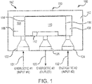
- Pyrotechnic transfer arrangement 192 includes an energetic one way sequence termination arrangement 100 (also referred to herein as an energetic one way sequence termination valve (STV)), a first energetic 131, a second energetic 132, and a third energetic 133.
- STV 100 comprises a housing 102 defining a cavity 104.
- a moveable shuttle 110 is disposed within housing 102.
- moveable shuttle 110 may comprise a recess 112. Housing 102 and/or moveable shuttle 110 may be metallic.
- STV 100 comprises a first inlet 122, a second inlet 124, and an outlet 126.
- First inlet 122, second inlet 124, and outlet 126 are in operable communication with the housing 102.
- First inlet 122, second inlet 124, and outlet 126 are in fluid communication with cavity 104.
- FIG. 1 depicts moveable shuttle 110 in a neutral position 190 with first inlet 122 in fluid communication with a first end 114 of moveable shuttle 110 and second inlet 124 in fluid communication with a second end 116 of moveable shuttle 110.
- moveable shuttle 110 in the neutral position 190, moveable shuttle 110 may define a first chamber 106 of cavity 104 and a second chamber 108 of cavity 104.
- STV 100 is coupled to the three energetics (i.e., first energetic 131, second energetic 132, and third energetic 133), via first inlet 122, second inlet 124, and outlet 126, respectively.
- the first energetic 131, second energetic 132, and third energetic 133 may comprise pyrotechnic transmission lines.
- a pyrotechnic transmission line may include a reactive material.
- the pyrotechnic transmission lines may be made, for example, of a material called "TLX" (trademark, Explosive Technology, Inc. of Fairfield, Calif.).
- TLX trademark, Explosive Technology, Inc. of Fairfield, Calif.
- the energetics may comprise any suitable pyrotechnic transmission line.
- the reactive material burns.
- the flame may propagate along the transmission line.
- first energetic 131 and second energetic 132 when the first energetic 131 and/or second energetic 132 ignite, the flame propagates along the transmission line towards STV 100.
- a pressurized fluid or gas is propagated into an inlet (e.g., first inlet 122 and/or second inlet 124) which builds pressure within cavity 104.
- the pressurized fluid or gas is propagated into STV 100, the STV 100 actuates.
- STV 100 actuates in response to ignition of the pyrotechnic transmission lines (i.e., first energetic 131 and/or second energetic 132).
- FIGs. 2A and 2B depict exemplary embodiments of a sequencing event of STV 100 in response to second energetic 132 igniting before first energetic 131, as explained below.
- moveable shuttle 110 is illustrated in the transferring position 290.
- a second signal 202 is received into cavity 104 in response to second energetic 132 being ignited before first energetic 131.
- the second signal 202 may moves or translates moveable shuttle 110 relative to housing 102.
- second chamber 108 increases in volume and first chamber 106 (see FIG. 1 ) decreases in volume.
- first inlet 122 in response to moveable shuttle 110 moving to the transferring position 290, first inlet 122 is in fluid communication with outlet 126. Stated differently, first inlet 122 establishes fluidic communication with outlet 126 in response to the second signal 202 being received at the second inlet 124 before the first signal 201 is received at the first inlet 122.
- recess 112 defines a connecting channel 204 through which first signal 201 may travel.
- First signal 201 may comprise a temperature and a pressure.
- Third energetic 133 may ignite in response to third energetic 133 receiving first signal 201.
- the output energy from first energetic 131 may comprise heat, expanding gases, a shock wave, and/or any other energy capable of actuating and/or igniting third energetic 133.
- FIGs. 3A and 3B depict exemplary embodiments of a sequencing event of STV 100 in response to second energetic 132 igniting after first energetic 131, as explained below.
- moveable shuttle 110 is illustrated in the terminating position 390.
- a first signal 301 is received into cavity 104 in response to first energetic 131 being ignited before second energetic 132.
- the first signal 301 moves or translates moveable shuttle 110 relative to housing 102.
- first chamber 106 increases in volume and second chamber 108 (see FIG. 1 ) decreases in volume.
- first inlet 122 is prevented from fluid communication with outlet 126.
- third energetic 133 may be prevented from igniting in response to first energetic 131 igniting before second energetic 132.
- Method 400 includes igniting a first energetic (step 410).
- Method 400 includes igniting a second energetic (step 420).
- Method 400 includes coupling a first inlet to an outlet (step 440).
- Method 400 includes igniting a third energetic (step 450).
- Method 400 includes preventing coupling of the first inlet to the outlet (step 460).
- step 410 includes igniting first energetic 131.
- Step 420 includes igniting second energetic 132.
- First energetic 131 and second energetic 132 may be ignited via any suitable means.
- method 400 may include only step 410, only step 420, or both step 410 and step 420.
- Step 440 may include coupling the first inlet 122 in fluid communication with outlet 126 in response to the moveable shuttle 110 moving to the transferring position 290. Stated differently, step 440 may include coupling the first inlet 122 in fluid communication with outlet 126 in response to second energetic 132 igniting before first energetic 131.
- Step 450 may include igniting third energetic 133.
- Step 460 includes preventing first inlet 122 from fluid communication with outlet 126 in response to the moveable shuttle 110 moving to the terminating position 390. Stated differently, step 460 includes preventing outlet 126 from fluid communication with first inlet 122 in response to first energetic 131 igniting before second energetic 132.
- the fluidic coupling or blocking thereof of step 440 and step 460 includes moving moveable shuttle 110. Moveable shuttle 110 may be moved from neutral position 190 to either transferring position 290 or terminating position 390.
- references to "one embodiment”, “an embodiment”, “various embodiments”, etc. indicate that the embodiment described may include a particular feature, structure, or characteristic, but every embodiment may not necessarily include the particular feature, structure, or characteristic. Moreover, such phrases are not necessarily referring to the same embodiment. Further, when a particular feature, structure, or characteristic is described in connection with an embodiment, it is submitted that it is within the knowledge of one skilled in the art to affect such feature, structure, or characteristic in connection with other embodiments whether or not explicitly described. After reading the description, it will be apparent to one skilled in the relevant art(s) how to implement the disclosure in alternative embodiments.
Landscapes
- Engineering & Computer Science (AREA)
- General Engineering & Computer Science (AREA)
- Mechanical Engineering (AREA)
- Physics & Mathematics (AREA)
- Fluid Mechanics (AREA)
- Business, Economics & Management (AREA)
- Emergency Management (AREA)
- Aviation & Aerospace Engineering (AREA)
- Measuring Fluid Pressure (AREA)
- Measuring Or Testing Involving Enzymes Or Micro-Organisms (AREA)
- Air Bags (AREA)
Claims (14)
- Dispositif énergétique de terminaison séquentielle à usage unique (100), comprenant :un boîtier (102) ;une première entrée (122) en communication fonctionnelle avec le boîtier ;une seconde entrée (124) en communication fonctionnelle avec le boîtier ; etune sortie (126) en communication fonctionnelle avec le boîtier,le dispositif énergétique de terminaison séquentielle à usage unique (100) étant configuré de sorte que la seconde entrée (124) ne peut pas être en communication fluidique avec la sortie (126), etla première entrée (122) établit une communication fluidique avec la sortie (126) en réponse à la réception du second signal au niveau de la seconde entrée (124) avant la réception du premier signal au niveau de la première entrée (122), ledit dispositif énergétique de terminaison séquentielle à usage unique comprenant en outre :une cavité (104) disposée à l'intérieur du boîtier (102) ; etune navette mobile (110) disposée à l'intérieur de la cavité (104),caractérisé par :la navette mobile (110) étant mobile entre une position neutre, une position de transfert et une position de terminaison ;la navette mobile (110) se déplaçant vers la position de terminaison en réponse au premier signal étant reçu en provenance de la première entrée (122) avant que le second signal ne soit reçu en provenance de la seconde entrée (124), etla navette mobile (110) se déplaçant vers la position de transfert en réponse au second signal étant reçu en provenance de la seconde entrée (124) avant que le premier signal ne soit reçu en provenance de la première entrée (122).
- Dispositif énergétique de terminaison séquentielle à usage unique selon la revendication 1, dans lequel la première entrée (122) est en communication fluidique avec la sortie (126) en réponse à la navette mobile (110) se déplaçant vers la position de transfert.
- Dispositif énergétique de terminaison séquentielle à usage unique selon la revendication 2, dans lequel la navette mobile (110) empêche la communication fluidique entre la sortie (126) et au moins l'une de la première entrée (122) et de la seconde entrée (124) en réponse à la navette mobile (110) se déplaçant vers la position de terminaison.
- Dispositif énergétique de terminaison séquentielle à usage unique selon la revendication 3, dans lequel la navette mobile (110) comprend un évidement définissant un canal de connexion (204),
dans lequel la première entrée (122) est en communication fluidique avec la sortie (126) par l'intermédiaire du canal de connexion en réponse au fait que la navette mobile (110) est en position de transfert, et de préférence
dans lequel au moins l'un du premier signal et du second signal comprend une pression capable de déplacer la navette mobile (110). - Dispositif énergétique de terminaison séquentielle à usage unique selon une quelconque revendication précédente, dans lequel au moins l'un du premier signal et du second signal comprend un signal de transmission pyrotechnique.
- Dispositif énergétique de terminaison séquentielle à usage unique selon une quelconque revendication précédente, dans lequel le dispositif énergétique de terminaison séquentielle à usage unique (100) est en métal.
- Dispositif de transfert pyrotechnique, comprenant :le dispositif énergétique de terminaison séquentielle à usage unique selon une quelconque revendication précédente ; etun premier dispositif énergétique (131) couplé à la première entrée (122) ;un deuxième dispositif énergétique (132) couplé à la seconde entrée (124) ; etun troisième dispositif énergétique (133) couplé à la sortie (126).
- Dispositif de transfert pyrotechnique selon la revendication 7, dans lequel la première entrée (122) est en communication fluidique avec la sortie (124) en réponse à la navette mobile (110) se déplaçant vers la position de transfert.
- Dispositif de transfert pyrotechnique selon la revendication 8, dans lequel
la navette mobile (110) empêche la communication fluidique entre la sortie (126) et au moins l'une de la première entrée (122) et de la seconde entrée (124) en réponse à la navette mobile (110) se déplaçant vers la position de terminaison, et
la première entrée (122) est en communication fluidique avec la sortie (126) en réponse au fait que la navette mobile (110) est en position de transfert. - Dispositif de transfert pyrotechnique selon la revendication 9, dans lequel
au moins l'un du premier signal et du second signal comprend une pression capable de déplacer la navette mobile (110), et
dans lequel au moins l'un du premier signal et du second signal comprend un signal de transmission pyrotechnique. - Dispositif de transfert pyrotechnique selon la revendication 10, dans lequel le premier signal est généré par le premier dispositif énergétique (131) et le troisième dispositif énergétique (133) est configuré pour se déclencher en réponse au premier signal reçu par le troisième dispositif énergétique (133).
- Dispositif de transfert pyrotechnique selon la revendication 11, dans lequel le second signal est généré par le deuxième dispositif énergétique (132) et la navette mobile (110) est configurée pour empêcher le troisième dispositif énergétique (133) de se déclencher en réponse au second signal reçu avant le premier signal, et/ou
dans lequel au moins l'un du premier dispositif énergétique (131), du deuxième dispositif énergétique (132) et du troisième dispositif énergétique (133) comprend une conduite de transmission pyrotechnique. - Procédé de séquençage d'un système pyrotechnique, comprenant :le déclenchement d'au moins l'un :d'un premier dispositif énergétique (131) couplé à une première entrée (122) d'un dispositif de terminaison séquentielle à usage unique ; etd'un deuxième dispositif énergétique (132) couplé à une seconde entrée (124) du dispositif de terminaison séquentielle à usage unique ;le couplage fluidique de la première entrée (122) à une sortie (126) du dispositif de terminaison séquentielle à usage unique en réponse au déclenchement du deuxième dispositif énergétique (132) avant que le premier dispositif énergétique (131) ne se déclenche ; etle blocage du couplage fluidique entre la seconde entrée (124) et la sortie (126), et caractérisé en ce qu'il comprend en outre :le déplacement, par une navette mobile (110), d'une position neutre à au moins l'une d'une position de transfert et d'une position de terminaison ;dans lequel la navette mobile (110) se déplace vers la position de transfert en réponse au déclenchement du deuxième dispositif énergétique (132) avant le premier dispositif énergétique, etdans lequel la navette mobile (110) se déplace vers la position de terminaison en réponse au déclenchement du premier dispositif énergétique (131) avant le deuxième dispositif énergétique (132).
- Procédé selon la revendication 13, comprenant en outre :le couplage de la première entrée (122) en communication fluidique avec la sortie (126) du dispositif de terminaison séquentielle à usage unique en réponse au déplacement de la navette mobile (110) vers la position de transfert ; etle déclenchement d'un troisième dispositif énergétique (133) couplé à la sortie (126) en réponse au déclenchement du premier dispositif énergétique (131),et comprenant en outre :
le fait d'empêcher la sortie (126) du dispositif de terminaison séquentielle à usage unique d'être en communication fluidique avec au moins l'une de la première entrée (122) et de la seconde entrée (124) en réponse au déplacement de la navette mobile (110) vers la position de terminaison.
Applications Claiming Priority (1)
| Application Number | Priority Date | Filing Date | Title |
|---|---|---|---|
| US15/428,777 US10253892B2 (en) | 2017-02-09 | 2017-02-09 | Energetic one way sequence termination valve |
Publications (2)
| Publication Number | Publication Date |
|---|---|
| EP3360782A1 EP3360782A1 (fr) | 2018-08-15 |
| EP3360782B1 true EP3360782B1 (fr) | 2020-04-15 |
Family
ID=61198691
Family Applications (1)
| Application Number | Title | Priority Date | Filing Date |
|---|---|---|---|
| EP18155869.3A Active EP3360782B1 (fr) | 2017-02-09 | 2018-02-08 | Soupape énergétique de terminaison séquencielle à usage unique |
Country Status (2)
| Country | Link |
|---|---|
| US (2) | US10253892B2 (fr) |
| EP (1) | EP3360782B1 (fr) |
Families Citing this family (1)
| Publication number | Priority date | Publication date | Assignee | Title |
|---|---|---|---|---|
| US10253892B2 (en) * | 2017-02-09 | 2019-04-09 | Goodrich Corporation | Energetic one way sequence termination valve |
Family Cites Families (19)
| Publication number | Priority date | Publication date | Assignee | Title |
|---|---|---|---|---|
| US3548848A (en) | 1968-06-03 | 1970-12-22 | Cartridge Actuated Devices | Explosive actuated valves |
| US3583157A (en) | 1969-10-06 | 1971-06-08 | Abex Corp | Hydrostatic transmission |
| US3805836A (en) * | 1971-04-12 | 1974-04-23 | C Veale | Fluid pressure responsive position control |
| US3951166A (en) * | 1974-06-12 | 1976-04-20 | Whitener Robert V | Rapid acting valve assembly |
| US3968729A (en) * | 1974-10-29 | 1976-07-13 | United Technologies Corporation | Fluid-operated apparatus exhibiting hysteresis effect |
| US4078579A (en) * | 1976-08-26 | 1978-03-14 | Frank E. Goodwin | Multiple port fluid control device |
| JPS5822858A (ja) | 1981-08-03 | 1983-02-10 | 株式会社東芝 | 差圧自動切換式三方弁 |
| US4448211A (en) | 1981-12-01 | 1984-05-15 | Tokyo Shibaura Denki Kabushiki Kaisha | Three-way valve |
| US4852612A (en) * | 1983-09-23 | 1989-08-01 | Bucko Sr Edward P | Fluid flow control device |
| GB8326702D0 (en) * | 1983-10-06 | 1983-11-09 | Brisland M J | Slide valve |
| DE3734136A1 (de) * | 1987-10-09 | 1989-04-20 | Festo Kg | Schieberventil |
| DE4042084A1 (de) * | 1990-12-28 | 1992-07-02 | Eberspaecher J | Magnet-wegeventil zur volumenstromsteuerung |
| US5247966A (en) * | 1991-01-11 | 1993-09-28 | Tahoe Surgical Instruments, Inc. | Suction irrigator valve apparatus |
| US5820162A (en) | 1996-03-21 | 1998-10-13 | Airbelt Systems, Llc. | Airbag system inflator |
| US7036521B2 (en) * | 2003-04-27 | 2006-05-02 | Carleton Life Support Systems, Inc. | Air conserving slide valve |
| JP4651394B2 (ja) * | 2005-01-13 | 2011-03-16 | 三菱電機株式会社 | 四方弁 |
| DE102013020585A1 (de) | 2013-12-13 | 2015-06-18 | Hydac Fluidtechnik Gmbh | Ventilvorrichtung |
| US9910469B2 (en) | 2014-12-18 | 2018-03-06 | The Boeing Company | DC-based peer-to-peer network for aircraft |
| US10253892B2 (en) * | 2017-02-09 | 2019-04-09 | Goodrich Corporation | Energetic one way sequence termination valve |
-
2017
- 2017-02-09 US US15/428,777 patent/US10253892B2/en active Active
-
2018
- 2018-02-08 EP EP18155869.3A patent/EP3360782B1/fr active Active
-
2019
- 2019-02-21 US US16/281,947 patent/US10385981B2/en active Active
Non-Patent Citations (1)
| Title |
|---|
| None * |
Also Published As
| Publication number | Publication date |
|---|---|
| US10385981B2 (en) | 2019-08-20 |
| US10253892B2 (en) | 2019-04-09 |
| US20180224007A1 (en) | 2018-08-09 |
| US20190186644A1 (en) | 2019-06-20 |
| EP3360782A1 (fr) | 2018-08-15 |
Similar Documents
| Publication | Publication Date | Title |
|---|---|---|
| EP3527929B1 (fr) | Mécanisme de mise à feu à explosif secondaire | |
| US3548848A (en) | Explosive actuated valves | |
| US3123099A (en) | High pressure fluid coupling | |
| US10739120B2 (en) | Explosive separating joint | |
| EP3360782B1 (fr) | Soupape énergétique de terminaison séquencielle à usage unique | |
| EP1840497B1 (fr) | Système et procédé d'armement | |
| EP3527930B1 (fr) | Adaptateur de transfert d'explosif à faible énergie | |
| US20090031912A1 (en) | Devices for firing a projectile | |
| US5337672A (en) | Locking device for a casing containing pyrotechnic materials | |
| EP0862044B1 (fr) | Allumeur comportant une cloison de séparation | |
| EP2102534B1 (fr) | Systèmes et procédés pour attacher un trajet de fluide à deux étages à des réservoirs de fluide pressurisés | |
| EP3482059B1 (fr) | Système hydraulique au sol avec injection de lingot hypergolique | |
| US3273335A (en) | Manifold ignition system for solid propellant rockets | |
| EP4109036A1 (fr) | Systèmes, procédés et dispositifs de temporisation | |
| CN102735119B (zh) | 一种引信用推动转盘转动的电推销器 | |
| EP1592912A1 (fr) | Dispositif de couplage de fiche de type machoire de serrage | |
| US4542761A (en) | Fluid delivery system | |
| US11815343B2 (en) | Dual input actuator for an output device | |
| KR100417005B1 (ko) | 로켓 탑재용 2단 또는 3단 추진기관 점화 안전 장치 | |
| RU2187683C2 (ru) | Двухрежимный ракетный двигатель твердого топлива | |
| EP4163582A1 (fr) | Système, procédé et dispositif de retard temporel | |
| EP0683097B1 (fr) | Dispositif de liaison | |
| US3263564A (en) | Impulse valve | |
| CN110486189A (zh) | 一种多级固体火箭发动机 |
Legal Events
| Date | Code | Title | Description |
|---|---|---|---|
| PUAI | Public reference made under article 153(3) epc to a published international application that has entered the european phase |
Free format text: ORIGINAL CODE: 0009012 |
|
| STAA | Information on the status of an ep patent application or granted ep patent |
Free format text: STATUS: THE APPLICATION HAS BEEN PUBLISHED |
|
| AK | Designated contracting states |
Kind code of ref document: A1 Designated state(s): AL AT BE BG CH CY CZ DE DK EE ES FI FR GB GR HR HU IE IS IT LI LT LU LV MC MK MT NL NO PL PT RO RS SE SI SK SM TR |
|
| AX | Request for extension of the european patent |
Extension state: BA ME |
|
| STAA | Information on the status of an ep patent application or granted ep patent |
Free format text: STATUS: REQUEST FOR EXAMINATION WAS MADE |
|
| 17P | Request for examination filed |
Effective date: 20190215 |
|
| RBV | Designated contracting states (corrected) |
Designated state(s): AL AT BE BG CH CY CZ DE DK EE ES FI FR GB GR HR HU IE IS IT LI LT LU LV MC MK MT NL NO PL PT RO RS SE SI SK SM TR |
|
| REG | Reference to a national code |
Ref country code: DE Ref legal event code: R079 Ref document number: 602018003682 Country of ref document: DE Free format text: PREVIOUS MAIN CLASS: B64D0025000000 Ipc: F16K0017340000 |
|
| GRAP | Despatch of communication of intention to grant a patent |
Free format text: ORIGINAL CODE: EPIDOSNIGR1 |
|
| STAA | Information on the status of an ep patent application or granted ep patent |
Free format text: STATUS: GRANT OF PATENT IS INTENDED |
|
| INTG | Intention to grant announced |
Effective date: 20191113 |
|
| RIC1 | Information provided on ipc code assigned before grant |
Ipc: F16K 11/065 20060101ALI20191105BHEP Ipc: F16K 31/122 20060101ALI20191105BHEP Ipc: F16K 17/34 20060101AFI20191105BHEP Ipc: B64D 25/00 20060101ALI20191105BHEP Ipc: F16K 17/00 20060101ALI20191105BHEP |
|
| RIN1 | Information on inventor provided before grant (corrected) |
Inventor name: CAMPBELL, MATTHEW Inventor name: SALOIS, MATTHEW |
|
| GRAS | Grant fee paid |
Free format text: ORIGINAL CODE: EPIDOSNIGR3 |
|
| GRAA | (expected) grant |
Free format text: ORIGINAL CODE: 0009210 |
|
| STAA | Information on the status of an ep patent application or granted ep patent |
Free format text: STATUS: THE PATENT HAS BEEN GRANTED |
|
| AK | Designated contracting states |
Kind code of ref document: B1 Designated state(s): AL AT BE BG CH CY CZ DE DK EE ES FI FR GB GR HR HU IE IS IT LI LT LU LV MC MK MT NL NO PL PT RO RS SE SI SK SM TR |
|
| REG | Reference to a national code |
Ref country code: CH Ref legal event code: EP |
|
| REG | Reference to a national code |
Ref country code: DE Ref legal event code: R096 Ref document number: 602018003682 Country of ref document: DE |
|
| REG | Reference to a national code |
Ref country code: IE Ref legal event code: FG4D |
|
| REG | Reference to a national code |
Ref country code: AT Ref legal event code: REF Ref document number: 1257703 Country of ref document: AT Kind code of ref document: T Effective date: 20200515 |
|
| REG | Reference to a national code |
Ref country code: NL Ref legal event code: MP Effective date: 20200415 |
|
| REG | Reference to a national code |
Ref country code: LT Ref legal event code: MG4D |
|
| PG25 | Lapsed in a contracting state [announced via postgrant information from national office to epo] |
Ref country code: IS Free format text: LAPSE BECAUSE OF FAILURE TO SUBMIT A TRANSLATION OF THE DESCRIPTION OR TO PAY THE FEE WITHIN THE PRESCRIBED TIME-LIMIT Effective date: 20200815 Ref country code: SE Free format text: LAPSE BECAUSE OF FAILURE TO SUBMIT A TRANSLATION OF THE DESCRIPTION OR TO PAY THE FEE WITHIN THE PRESCRIBED TIME-LIMIT Effective date: 20200415 Ref country code: GR Free format text: LAPSE BECAUSE OF FAILURE TO SUBMIT A TRANSLATION OF THE DESCRIPTION OR TO PAY THE FEE WITHIN THE PRESCRIBED TIME-LIMIT Effective date: 20200716 Ref country code: NO Free format text: LAPSE BECAUSE OF FAILURE TO SUBMIT A TRANSLATION OF THE DESCRIPTION OR TO PAY THE FEE WITHIN THE PRESCRIBED TIME-LIMIT Effective date: 20200715 Ref country code: FI Free format text: LAPSE BECAUSE OF FAILURE TO SUBMIT A TRANSLATION OF THE DESCRIPTION OR TO PAY THE FEE WITHIN THE PRESCRIBED TIME-LIMIT Effective date: 20200415 Ref country code: LT Free format text: LAPSE BECAUSE OF FAILURE TO SUBMIT A TRANSLATION OF THE DESCRIPTION OR TO PAY THE FEE WITHIN THE PRESCRIBED TIME-LIMIT Effective date: 20200415 Ref country code: PT Free format text: LAPSE BECAUSE OF FAILURE TO SUBMIT A TRANSLATION OF THE DESCRIPTION OR TO PAY THE FEE WITHIN THE PRESCRIBED TIME-LIMIT Effective date: 20200817 Ref country code: NL Free format text: LAPSE BECAUSE OF FAILURE TO SUBMIT A TRANSLATION OF THE DESCRIPTION OR TO PAY THE FEE WITHIN THE PRESCRIBED TIME-LIMIT Effective date: 20200415 |
|
| REG | Reference to a national code |
Ref country code: AT Ref legal event code: MK05 Ref document number: 1257703 Country of ref document: AT Kind code of ref document: T Effective date: 20200415 |
|
| PG25 | Lapsed in a contracting state [announced via postgrant information from national office to epo] |
Ref country code: HR Free format text: LAPSE BECAUSE OF FAILURE TO SUBMIT A TRANSLATION OF THE DESCRIPTION OR TO PAY THE FEE WITHIN THE PRESCRIBED TIME-LIMIT Effective date: 20200415 Ref country code: RS Free format text: LAPSE BECAUSE OF FAILURE TO SUBMIT A TRANSLATION OF THE DESCRIPTION OR TO PAY THE FEE WITHIN THE PRESCRIBED TIME-LIMIT Effective date: 20200415 Ref country code: LV Free format text: LAPSE BECAUSE OF FAILURE TO SUBMIT A TRANSLATION OF THE DESCRIPTION OR TO PAY THE FEE WITHIN THE PRESCRIBED TIME-LIMIT Effective date: 20200415 Ref country code: BG Free format text: LAPSE BECAUSE OF FAILURE TO SUBMIT A TRANSLATION OF THE DESCRIPTION OR TO PAY THE FEE WITHIN THE PRESCRIBED TIME-LIMIT Effective date: 20200715 |
|
| PG25 | Lapsed in a contracting state [announced via postgrant information from national office to epo] |
Ref country code: AL Free format text: LAPSE BECAUSE OF FAILURE TO SUBMIT A TRANSLATION OF THE DESCRIPTION OR TO PAY THE FEE WITHIN THE PRESCRIBED TIME-LIMIT Effective date: 20200415 |
|
| REG | Reference to a national code |
Ref country code: DE Ref legal event code: R097 Ref document number: 602018003682 Country of ref document: DE |
|
| PG25 | Lapsed in a contracting state [announced via postgrant information from national office to epo] |
Ref country code: IT Free format text: LAPSE BECAUSE OF FAILURE TO SUBMIT A TRANSLATION OF THE DESCRIPTION OR TO PAY THE FEE WITHIN THE PRESCRIBED TIME-LIMIT Effective date: 20200415 Ref country code: CZ Free format text: LAPSE BECAUSE OF FAILURE TO SUBMIT A TRANSLATION OF THE DESCRIPTION OR TO PAY THE FEE WITHIN THE PRESCRIBED TIME-LIMIT Effective date: 20200415 Ref country code: RO Free format text: LAPSE BECAUSE OF FAILURE TO SUBMIT A TRANSLATION OF THE DESCRIPTION OR TO PAY THE FEE WITHIN THE PRESCRIBED TIME-LIMIT Effective date: 20200415 Ref country code: ES Free format text: LAPSE BECAUSE OF FAILURE TO SUBMIT A TRANSLATION OF THE DESCRIPTION OR TO PAY THE FEE WITHIN THE PRESCRIBED TIME-LIMIT Effective date: 20200415 Ref country code: AT Free format text: LAPSE BECAUSE OF FAILURE TO SUBMIT A TRANSLATION OF THE DESCRIPTION OR TO PAY THE FEE WITHIN THE PRESCRIBED TIME-LIMIT Effective date: 20200415 Ref country code: EE Free format text: LAPSE BECAUSE OF FAILURE TO SUBMIT A TRANSLATION OF THE DESCRIPTION OR TO PAY THE FEE WITHIN THE PRESCRIBED TIME-LIMIT Effective date: 20200415 Ref country code: SM Free format text: LAPSE BECAUSE OF FAILURE TO SUBMIT A TRANSLATION OF THE DESCRIPTION OR TO PAY THE FEE WITHIN THE PRESCRIBED TIME-LIMIT Effective date: 20200415 Ref country code: DK Free format text: LAPSE BECAUSE OF FAILURE TO SUBMIT A TRANSLATION OF THE DESCRIPTION OR TO PAY THE FEE WITHIN THE PRESCRIBED TIME-LIMIT Effective date: 20200415 |
|
| PLBE | No opposition filed within time limit |
Free format text: ORIGINAL CODE: 0009261 |
|
| STAA | Information on the status of an ep patent application or granted ep patent |
Free format text: STATUS: NO OPPOSITION FILED WITHIN TIME LIMIT |
|
| PG25 | Lapsed in a contracting state [announced via postgrant information from national office to epo] |
Ref country code: PL Free format text: LAPSE BECAUSE OF FAILURE TO SUBMIT A TRANSLATION OF THE DESCRIPTION OR TO PAY THE FEE WITHIN THE PRESCRIBED TIME-LIMIT Effective date: 20200415 Ref country code: SK Free format text: LAPSE BECAUSE OF FAILURE TO SUBMIT A TRANSLATION OF THE DESCRIPTION OR TO PAY THE FEE WITHIN THE PRESCRIBED TIME-LIMIT Effective date: 20200415 |
|
| 26N | No opposition filed |
Effective date: 20210118 |
|
| PG25 | Lapsed in a contracting state [announced via postgrant information from national office to epo] |
Ref country code: SI Free format text: LAPSE BECAUSE OF FAILURE TO SUBMIT A TRANSLATION OF THE DESCRIPTION OR TO PAY THE FEE WITHIN THE PRESCRIBED TIME-LIMIT Effective date: 20200415 |
|
| PG25 | Lapsed in a contracting state [announced via postgrant information from national office to epo] |
Ref country code: MC Free format text: LAPSE BECAUSE OF FAILURE TO SUBMIT A TRANSLATION OF THE DESCRIPTION OR TO PAY THE FEE WITHIN THE PRESCRIBED TIME-LIMIT Effective date: 20200415 |
|
| REG | Reference to a national code |
Ref country code: BE Ref legal event code: MM Effective date: 20210228 |
|
| PG25 | Lapsed in a contracting state [announced via postgrant information from national office to epo] |
Ref country code: CH Free format text: LAPSE BECAUSE OF NON-PAYMENT OF DUE FEES Effective date: 20210228 Ref country code: LU Free format text: LAPSE BECAUSE OF NON-PAYMENT OF DUE FEES Effective date: 20210208 Ref country code: LI Free format text: LAPSE BECAUSE OF NON-PAYMENT OF DUE FEES Effective date: 20210228 |
|
| PG25 | Lapsed in a contracting state [announced via postgrant information from national office to epo] |
Ref country code: IE Free format text: LAPSE BECAUSE OF NON-PAYMENT OF DUE FEES Effective date: 20210208 |
|
| PG25 | Lapsed in a contracting state [announced via postgrant information from national office to epo] |
Ref country code: BE Free format text: LAPSE BECAUSE OF NON-PAYMENT OF DUE FEES Effective date: 20210228 |
|
| P01 | Opt-out of the competence of the unified patent court (upc) registered |
Effective date: 20230522 |
|
| PG25 | Lapsed in a contracting state [announced via postgrant information from national office to epo] |
Ref country code: CY Free format text: LAPSE BECAUSE OF FAILURE TO SUBMIT A TRANSLATION OF THE DESCRIPTION OR TO PAY THE FEE WITHIN THE PRESCRIBED TIME-LIMIT Effective date: 20200415 |
|
| PG25 | Lapsed in a contracting state [announced via postgrant information from national office to epo] |
Ref country code: HU Free format text: LAPSE BECAUSE OF FAILURE TO SUBMIT A TRANSLATION OF THE DESCRIPTION OR TO PAY THE FEE WITHIN THE PRESCRIBED TIME-LIMIT; INVALID AB INITIO Effective date: 20180208 |
|
| PG25 | Lapsed in a contracting state [announced via postgrant information from national office to epo] |
Ref country code: MK Free format text: LAPSE BECAUSE OF FAILURE TO SUBMIT A TRANSLATION OF THE DESCRIPTION OR TO PAY THE FEE WITHIN THE PRESCRIBED TIME-LIMIT Effective date: 20200415 |
|
| PG25 | Lapsed in a contracting state [announced via postgrant information from national office to epo] |
Ref country code: TR Free format text: LAPSE BECAUSE OF FAILURE TO SUBMIT A TRANSLATION OF THE DESCRIPTION OR TO PAY THE FEE WITHIN THE PRESCRIBED TIME-LIMIT Effective date: 20200415 |
|
| PG25 | Lapsed in a contracting state [announced via postgrant information from national office to epo] |
Ref country code: MT Free format text: LAPSE BECAUSE OF FAILURE TO SUBMIT A TRANSLATION OF THE DESCRIPTION OR TO PAY THE FEE WITHIN THE PRESCRIBED TIME-LIMIT Effective date: 20200415 |
|
| PGFP | Annual fee paid to national office [announced via postgrant information from national office to epo] |
Ref country code: GB Payment date: 20260121 Year of fee payment: 9 |
|
| PGFP | Annual fee paid to national office [announced via postgrant information from national office to epo] |
Ref country code: DE Payment date: 20260121 Year of fee payment: 9 |
|
| PGFP | Annual fee paid to national office [announced via postgrant information from national office to epo] |
Ref country code: FR Payment date: 20260121 Year of fee payment: 9 |