EP3361353A1 - Interface gestuelle et table de concordance des parametres pour modèle physique d' instrument a cordes - Google Patents
Interface gestuelle et table de concordance des parametres pour modèle physique d' instrument a cordes Download PDFInfo
- Publication number
- EP3361353A1 EP3361353A1 EP17382060.6A EP17382060A EP3361353A1 EP 3361353 A1 EP3361353 A1 EP 3361353A1 EP 17382060 A EP17382060 A EP 17382060A EP 3361353 A1 EP3361353 A1 EP 3361353A1
- Authority
- EP
- European Patent Office
- Prior art keywords
- input signals
- sound
- digital input
- synthesizer
- sensor
- Prior art date
- Legal status (The legal status is an assumption and is not a legal conclusion. Google has not performed a legal analysis and makes no representation as to the accuracy of the status listed.)
- Withdrawn
Links
Images




Classifications
-
- G—PHYSICS
- G10—MUSICAL INSTRUMENTS; ACOUSTICS
- G10H—ELECTROPHONIC MUSICAL INSTRUMENTS; INSTRUMENTS IN WHICH THE TONES ARE GENERATED BY ELECTROMECHANICAL MEANS OR ELECTRONIC GENERATORS, OR IN WHICH THE TONES ARE SYNTHESISED FROM A DATA STORE
- G10H1/00—Details of electrophonic musical instruments
- G10H1/02—Means for controlling the tone frequencies, e.g. attack or decay; Means for producing special musical effects, e.g. vibratos or glissandos
- G10H1/04—Means for controlling the tone frequencies, e.g. attack or decay; Means for producing special musical effects, e.g. vibratos or glissandos by additional modulation
- G10H1/053—Means for controlling the tone frequencies, e.g. attack or decay; Means for producing special musical effects, e.g. vibratos or glissandos by additional modulation during execution only
- G10H1/055—Means for controlling the tone frequencies, e.g. attack or decay; Means for producing special musical effects, e.g. vibratos or glissandos by additional modulation during execution only by switches with variable impedance elements
-
- G—PHYSICS
- G10—MUSICAL INSTRUMENTS; ACOUSTICS
- G10H—ELECTROPHONIC MUSICAL INSTRUMENTS; INSTRUMENTS IN WHICH THE TONES ARE GENERATED BY ELECTROMECHANICAL MEANS OR ELECTRONIC GENERATORS, OR IN WHICH THE TONES ARE SYNTHESISED FROM A DATA STORE
- G10H1/00—Details of electrophonic musical instruments
- G10H1/0091—Means for obtaining special acoustic effects
-
- G—PHYSICS
- G10—MUSICAL INSTRUMENTS; ACOUSTICS
- G10H—ELECTROPHONIC MUSICAL INSTRUMENTS; INSTRUMENTS IN WHICH THE TONES ARE GENERATED BY ELECTROMECHANICAL MEANS OR ELECTRONIC GENERATORS, OR IN WHICH THE TONES ARE SYNTHESISED FROM A DATA STORE
- G10H1/00—Details of electrophonic musical instruments
- G10H1/46—Volume control
-
- G—PHYSICS
- G10—MUSICAL INSTRUMENTS; ACOUSTICS
- G10H—ELECTROPHONIC MUSICAL INSTRUMENTS; INSTRUMENTS IN WHICH THE TONES ARE GENERATED BY ELECTROMECHANICAL MEANS OR ELECTRONIC GENERATORS, OR IN WHICH THE TONES ARE SYNTHESISED FROM A DATA STORE
- G10H2220/00—Input/output interfacing specifically adapted for electrophonic musical tools or instruments
- G10H2220/155—User input interfaces for electrophonic musical instruments
- G10H2220/201—User input interfaces for electrophonic musical instruments for movement interpretation, i.e. capturing and recognizing a gesture or a specific kind of movement, e.g. to control a musical instrument
-
- G—PHYSICS
- G10—MUSICAL INSTRUMENTS; ACOUSTICS
- G10H—ELECTROPHONIC MUSICAL INSTRUMENTS; INSTRUMENTS IN WHICH THE TONES ARE GENERATED BY ELECTROMECHANICAL MEANS OR ELECTRONIC GENERATORS, OR IN WHICH THE TONES ARE SYNTHESISED FROM A DATA STORE
- G10H2220/00—Input/output interfacing specifically adapted for electrophonic musical tools or instruments
- G10H2220/155—User input interfaces for electrophonic musical instruments
- G10H2220/401—3D sensing, i.e. three-dimensional (x, y, z) position or movement sensing
-
- G—PHYSICS
- G10—MUSICAL INSTRUMENTS; ACOUSTICS
- G10H—ELECTROPHONIC MUSICAL INSTRUMENTS; INSTRUMENTS IN WHICH THE TONES ARE GENERATED BY ELECTROMECHANICAL MEANS OR ELECTRONIC GENERATORS, OR IN WHICH THE TONES ARE SYNTHESISED FROM A DATA STORE
- G10H2220/00—Input/output interfacing specifically adapted for electrophonic musical tools or instruments
- G10H2220/155—User input interfaces for electrophonic musical instruments
- G10H2220/405—Beam sensing or control, i.e. input interfaces involving substantially immaterial beams, radiation, or fields of any nature, used, e.g. as a switch as in a light barrier, or as a control device, e.g. using the theremin electric field sensing principle
-
- G—PHYSICS
- G10—MUSICAL INSTRUMENTS; ACOUSTICS
- G10H—ELECTROPHONIC MUSICAL INSTRUMENTS; INSTRUMENTS IN WHICH THE TONES ARE GENERATED BY ELECTROMECHANICAL MEANS OR ELECTRONIC GENERATORS, OR IN WHICH THE TONES ARE SYNTHESISED FROM A DATA STORE
- G10H2230/00—General physical, ergonomic or hardware implementation of electrophonic musical tools or instruments, e.g. shape or architecture
- G10H2230/045—Special instrument [spint], i.e. mimicking the ergonomy, shape, sound or other characteristic of a specific acoustic musical instrument category
- G10H2230/155—Spint wind instrument, i.e. mimicking musical wind instrument features; Electrophonic aspects of acoustic wind instruments; MIDI-like control therefor
-
- G—PHYSICS
- G10—MUSICAL INSTRUMENTS; ACOUSTICS
- G10H—ELECTROPHONIC MUSICAL INSTRUMENTS; INSTRUMENTS IN WHICH THE TONES ARE GENERATED BY ELECTROMECHANICAL MEANS OR ELECTRONIC GENERATORS, OR IN WHICH THE TONES ARE SYNTHESISED FROM A DATA STORE
- G10H2240/00—Data organisation or data communication aspects, specifically adapted for electrophonic musical tools or instruments
- G10H2240/075—Musical metadata derived from musical analysis or for use in electrophonic musical instruments
Definitions
- Any object that produces sound can be considered a musical instrument-it is through purpose that the object becomes a musical instrument.
- the process of converting a bodily action into a sound through an object or instrument is sometimes direct, for example using an idiophone, or indirect, for example using an electromechanical instrument.
- Electromechanical instruments typically comprise an electronic or digital sound module which produces a synthesized or sampled sound and one or more electric sensors to trigger the sounds.
- the synthesized sound needs to synchronize the signals received from the sensors in order to avoid lag between the bodily action that triggers the sensor and the sound generation.
- a method of synthesizing sounds in a multisensory sound system comprises identifying first analog input signals at a pressure sensor and respective second analog input signals at a 3D tracking sensor in response to one or more user gestures; generating first digital input signals by sampling the first analog input signals; transmitting the first digital input signals to a synthesizer; identifying at least a first set of sound parameters at the synthesizer associated with the first digital input signals; generating second digital input signals by processing the second analog input signals; transmitting the second digital input signals to the synthesizer, wherein the second digital input signals are received by the synthesizer with a delay with respect to the respective first digital input signals; identifying at least a second set of sound parameters at the synthesizer associated with the second digital input signals; Summing the identified first and second sets of parameters to generate a synthesized sound as a function of the identified parameters.
- the musician may be to generate single sounds with single gestures or bodily actions, by selecting different sound parameters in response to the signals received by different sensors, a smooth transition effect may be produced and the musician may thus not perceive any lag or delay between the bodily action or gesture and the generation of the sound even if the respective signals arrive at the synthesizer at different times.
- the perception of a lagging sound i.e. a sound that may arrive with delay due to latency of one or more of the processing elements, is generally subjective. Trained musicians may perceive a delay where an untrained ear may not. However, there are various thresholds, in the order of 10 milliseconds, where even the more trained ear may not perceive any lag. Thus, if the first digital signal arrives at the synthesizer within such a threshold, whereas the second digital signal arrives beyond such a threshold, it is possible that the trained musician may perceive the delay and consider the sound system as defective.
- a stream of signals from the pressure sensor may thus combine with a stream of signals from the 3D tracking sensor and generate a continuous stream of sounds and sound effects through the selection of different sound parameters and, therefore, no lagging or delay may be perceived by the trained ear.
- identifying first analog input signals may comprise pressing a pad attached to the pressure sensor. Such pressing may trigger the pressure sensor and generate the first digital signals.
- the pad may have various pressure points and the pressure sensor may detect pressure at any pressure point.
- the pressure sensor may detect any pressure above a predetermined threshold and sample the received pressure signal to generate the first digital input signal associated with the pressure intensity.
- the pressure sensor values may range between the predetermined threshold and a peak value.
- the synthesizer may then receive peak values and select sound parameters that may correspond to a musical note.
- the synthesizer may receive envelope values and select sound parameters associated to the envelope values received, associated with the musical note, e.g.
- the synthesizer may maintain the effect, i.e. maintain the activation of the pressure effect, until pressure is below the predetermined threshold.
- the synthesizer may then trigger or emit a sound based on the selected sound parameters.
- identifying a second analog input signal may comprise identifying a movement above the 3D tracking sensor.
- the 3D tracking sensor may comprise a series of antennas distributed around the pad.
- the antennas may define zones and changes in the electromagnetic field of the zones may indicate movement in one or more of the defined zones. For example, successive excitation of two consecutive zones may indicate distance, movement along one direction and/or speed.
- identifying a movement may comprise measuring a distance of a moving element from the 3D tracking sensor.
- the movement may be identified as a hovering movement when the distance is greater than a predetermined threshold.
- the predetermined threshold may substantially coincide with the distance of a pad surface (e.g. the upper or external surface of the pad) from the 3D tracking sensor that may lie below the pad.
- the movement may be identified as a stroking movement.
- generating a first synthesized sound may comprise combining the selected first and second sound parameters.
- the method may further comprise receiving a plurality of first and second analog input signals at a plurality of pressure and 3D tracking sensors. A complex synthesized sound may then be generated and the complex synthesized sound may be mixed or processed at an output.
- a sound system may comprise pressure sensors to receive first analog input signals.
- the sound system may further comprise 3D tracking sensors to receive second analog input signals.
- the sound system may further comprise interaction pads arranged outwards from (e.g. above) the pressure and 3D tracking sensors, respectively.
- a controller may receive first analog input signals from the pressure sensors and second analog input signals from the 3D tracking sensors.
- a communications interface may receive first and second digital input signals and transmit them to the synthesizer.
- the synthesizer may be configured select first set of sound parameters and receive the second digital input signals and select second set of sound parameters, whereby the synthesizer is configured to generate a synthesized sound as a function of the selected first and second sets of sound parameters.
- the sound system may comprise an instrument module and the synthesizer may be internal or external to the instrument module.
- the communication interface may be wired or wireless.
- the instrument module may comprise an ovoid case
- the ovoid case may comprise an upper hemisphere with apertures that may host the interaction pads.
- the interaction pads may be radially distributed around the center of the hemisphere.
- Each interaction pad may be coupled to a pressure and a 3D tracking sensor, respectively.
- each aperture may host a sensor base.
- the respective pressure sensor and 3D tracking sensor may be coupled to the sensor base.
- the sensor base may comprise support elements and the interaction pads may be mechanically attached to the support elements.
- the support elements may have resilient elements distributed below the respective interaction pad.
- the interaction pad may comprise an external surface.
- the support elements may be configured to maintain the external surface at a predetermined distance or distance range from the sensor base. Thus predetermined distances or distance ranges may be defined to help identify gestures as hovering movements or as stroking movements.
- the sound system may further comprise light sources, such as LEDs, to indicate interaction with the sound system.
- a computer program product may comprise program instructions for causing a computing system to perform a method of synthesizing sounds in a multisensory sound system according to some examples disclosed herein.
- the computer program product may be embodied on a storage medium (for example, a CD-ROM, a DVD, a USB drive, on a computer memory or on a read-only memory) or carried on a carrier signal (for example, on an electrical or optical carrier signal).
- a storage medium for example, a CD-ROM, a DVD, a USB drive, on a computer memory or on a read-only memory
- a carrier signal for example, on an electrical or optical carrier signal
- the computer program may be in the form of source code, object code, a code intermediate source and object code such as in partially compiled form, or in any other form suitable for use in the implementation of the processes.
- the carrier may be any entity or device capable of carrying the computer program.
- the carrier may comprise a storage medium, such as a ROM, for example a CD ROM or a semiconductor ROM, or a magnetic recording medium, for example a hard disk.
- a storage medium such as a ROM, for example a CD ROM or a semiconductor ROM, or a magnetic recording medium, for example a hard disk.
- the carrier may be a transmissible carrier such as an electrical or optical signal, which may be conveyed via electrical or optical cable or by radio or other means.
- the carrier may be constituted by such cable or other device or means.
- the carrier may be an integrated circuit in which the computer program is embedded, the integrated circuit being adapted for performing, or for use in the performance of, the relevant methods.
- Fig. 1 is a block diagram of a multisensory sound system (MSS).
- MSS 100 may comprise an instrument unit 105, a sound synthesizer 130 and a reproduction unit 140.
- the instrument unit may comprise interaction pads 110. Although two such pads are shown, the skilled person may appreciate that the instrument unit may comprise any number of pads.
- Each interaction pad 110 may comprise a 3D tracking sensor 112, a pressure sensor 114 and an LED unit 116.
- the LED unit may be connected to LED controller 118.
- the instrument unit 105 may further comprise a data and power bus 120.
- the instrument unit 105 may further comprise a central controller 125.
- the central controller 125 may comprise a processing unit 127 and a communication module 129.
- the communication module 129 may transmit digital signals to the sound synthesizer 130.
- the sound synthesizer 130 may receive the digital signals and generate sound signals that may be reproduced at the reproduction unit 140.
- Fig. 2 schematically illustrates an MSS with a hang-type instrument unit.
- the instrument unit 200 is an electronical device with an ovoid geometry.
- the instrument unit may comprise an ovoid housing with various oval holes on the upper hemisphere and one central circular hole at the north pole.
- Support elements may be placed under the holes and the interaction pads 205 may be mechanically attached to the support elements.
- the support elements may have soft resilient elements distributed at their periphery and one central resilient element.
- All the different areas of interaction may be provided with the same functionalities.
- Two different sensors may control the pressure over the pad, the position of the hand respect the center of area, 3D gestures and the 3D position from the surface of the pad to several centimeters of it.
- an RGB LED may give instant feedback to the user 201 during interaction.
- the LEDs may be integrated on the little groove in the upper part.
- seven LEDs may be integrated around the periphery.
- the interaction pads may have a cover and a sensor base.
- the sensor base may have a pressure sensor, and a 3D tracking sensor arranged around the periphery of the pad.
- a touch controller on the sensor base may receive signals from the pressure sensors and process all the information through a microprocessor, e.g. an ARM Cortex microprocessor, with embedded firmware.
- the interaction pads may have one or more LEDs attached to the cover and connected through the sensor base.
- the LEDs may be remotely controlled by a software or by an audio engine that may be integrated in the instrument unit or that may be external to the instrument unit.
- Each interaction pad may comprise resilient pieces distributed under the pad surface that may control the stability and allow the movement of the component. Four of them may be distributed at the periphery, working as a compression spring, and one may be in the center, to actuate on the pressure sensor.
- a screw e.g. a Polyamide screw, may fix the button to the case, allowing the movement of the system, but preventing the set to pull apart.
- the same configuration may be adopted in all or part of the interaction pads, generating the same characteristics and feelings at all points of interaction.
- a central electronic board On the inside a central electronic board may be suspended, separated by four plastic fasteners.
- a metal piece may be holding the different connectors.
- a circular rubbery piece may be all around the base to ensure grip and stability of the system over a surface. This same part may be responsible for facilitating the passage of cables, without unbalancing the instrument.
- the MSS may further comprise a synthesizer 215 and a sound reproduction unit 220.
- the reproduction unit may comprise or may be connected to a speaker or loudspeaker 225.
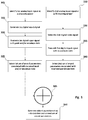
- first analogue input signals may be received at a pressure sensor. They may correspond to a pressure or strike movement of the user to the pad hosting the pressure sensor.
- second analogue input signals may be received at a 3D tracking sensor. The may correspond to changes in the electrical field measured by the 3D tracking sensor.
- first digital input signals may be generated by sampling the first analogue input signals.
- the first digital input signals may comprise peak values of the analogue signal and/or the envelope of the signal. In some cases an analogue signal may be a simple strike with no remaining pressure. Thus, the first digital input signal may only comprise a peak value.
- the analogue signal may be a strike followed by varying levels of pressure on the pad and consequently on the pressure sensor.
- the first digital input signals may comprise peak and envelope values.
- the peak value may comprise the velocity (intensity) of the signal.
- no strike may take place and the user may gradually pressure the pad, and consequently the pressure sensor.
- the pressure sensor detects a pressure above a predetermined threshold, it may start generating enevelope values.
- the first digital input signal may comprise only envelope values. While the first analog input signals remain above a predetermined threshold the pressure sensor may perceive the first analog input signals received as part of a single pressure event. For example, the user may strike the pad and maintain pressure afterwards on the pad.
- the pressure sensor may measure pressure above the threshold for an extended period of time. During this time there may be various fluctuations of pressure that may correspond to movements of the user's hand around the pad.
- the first digital input signals may be transmitted to a synthesizer.
- a set of first digital input signals may correspond to a pressure event.
- a pressure event may start when a sample of the analog input signal is measured above the threshold and may end when a sample of the analog input signal is below the threshold. All intermediate samples may be considered part of the pressure event.
- the synthesizer may receive the peak and/or envelope values and a first set of sound parameters may be identified. The synthesizer may have a sound or a musical note associated to each pad.
- a second digital input signal may be generated by processing the second analogue signal.
- the second digital input signal may comprise coordinate values, e.g.
- the second digital input signal may be transmitted to the synthesizer.
- the second digital signal may be received by the synthesizer with a delay with respect to the first digital signal.
- the synthesizer may have preassigned parameters associated with X,Y position values.
- the parameter may be one of the parameters previously mentioned.
- the envelope values may have different preassigned parameters than the coordinate values.
- the synthesizer may then select, in block 340, the preassigned parameter for the coordinate values and apply the parameter to the associated sound or musical note. As the coordinates change, so may change the value of the associated parameter.
- the first set of selected sound parameters and the second set of selected sound parameters may be summed, combined or aggregated to generate at block 350 the mixed sound, at any given moment and for any interaction pad, as a function of the selected parameters.
- Fig. 4 is an exploded view of a multisensory sound system instrument according to an example.
- the instrument 400 may comprise an upper housing 401 and a lower housing 402.
- the upper housing may comprise openings, e.g. oval shaped openings, to host interaction pads.
- the lower housing may comprise a central opening.
- a base 403 may be hosted in the opening of the lower case 402.
- the base 403 may be resilient and/or have a shape to allow comfortable rest on a user's lap.
- the instrument 400 may also comprise interaction pads. Interaction pads may comprise pad supports 408, printed circuit board (PCB) pads 412, intermediate clips 415 and pad surface caps 407.
- the PCB pads 412 may be attached to the pad supports 408, respectively.
- the PCB pads may comprise pressure and 3D tracking sensors.
- the intermediate clips 415 may separate the PCB pads 412 from the pad surface caps 407.
- the pad surface caps 407 may clip on the intermediate clips 415 so that the pad surface caps 407, used for interaction of the user with the instrument, do not directly sit on the PCB pads 412.
- the instrument 400 may further comprise a central pad 427 that may have similar or distinct functionality to the other interaction pads.
- the instrument 400 may have a controller (not shown) hosted in the instrument and connected to the PCB pads and communication and power source module 440 that may provide connections, communication ports, power ports, batteries etc.
- the module 440 may be connected to the controller and to the PCB pads 412.
- Interaction pad 500 may comprise pad support 505, PCB pads 510, intermediate clips 515 and pad surface cap 520.
- the pad supports 505 may have an ovoid shape with raised periphery and may host resilient elements 506 and sensor actuator 507.
- the PCB pad 510 may comprise a pressure sensor 512 and a 3D and tracking sensor 514.
- the intermediate clip 515 and the pad surface cap 520 may have an aperture, respectively to host a LED light diffuser 517.
- the LED light diffuser 517 may be configured to contact LED light 516 when the interaction pad is mounted.
- the interaction pad 500 may further comprise a resilient pocket 518, attached to a protrusion of the PCB pad 510 to absorve vibrations when the interaction pad is struck or pressed. The various pieces of the interaction pad may be held together with screws 519.
- DSP Digital Signal Processor
- ASIC Application Specific Integrated Circuit
- FPGA Field Programmable Gate Array
- a general purpose processor may be a microprocessor, but in the alternative, the processor may be any conventional processor, controller, microcontroller, or state machine.
- a processor may also be implemented as a combination of computing devices, e.g., a combination of a DSP and a microprocessor, a plurality of microprocessors, one or more microprocessors in conjunction with a DSP core, or any other such configuration.
- a software module may reside in Random Access Memory (RAM), flash memory, Read Only Memory (ROM), Electrically Programmable ROM (EPROM), Electrically Erasable Programmable ROM (EEPROM), registers, hard disk, a removable disk, a CD-ROM, or any other form of storage medium known in the art.
- An exemplary storage medium is coupled to the processor such that the processor can read information from, and write information to, the storage medium.
- the storage medium may be integral to the processor.
- the processor and the storage medium may reside in an ASIC.
- the ASIC may reside in a user terminal.
- the processor and the storage medium may reside as discrete components in a user terminal.
- the functions described may be implemented in hardware, software, firmware, or any combination thereof. If implemented in software, the functions may be stored on or transmitted over as one or more instructions or code on a computer-readable medium.
- Computer-readable media includes both computer storage media and communication media including any medium that facilitates transfer of a computer program from one place to another.
- a storage media may be any available media that can be accessed by a computer.
- such computer-readable media can comprise RAM, ROM, EEPROM, CD-ROM or other optical disk storage, magnetic disk storage or other magnetic storage devices, or any other medium that can be used to carry or store desired program code in the form of instructions or data structures and that can be accessed by a computer.
- any connection is properly termed a computer-readable medium.
Landscapes
- Physics & Mathematics (AREA)
- Engineering & Computer Science (AREA)
- Acoustics & Sound (AREA)
- Multimedia (AREA)
- Electrophonic Musical Instruments (AREA)
Priority Applications (1)
| Application Number | Priority Date | Filing Date | Title |
|---|---|---|---|
| EP17382060.6A EP3361353A1 (fr) | 2017-02-08 | 2017-02-08 | Interface gestuelle et table de concordance des parametres pour modèle physique d' instrument a cordes |
Applications Claiming Priority (1)
| Application Number | Priority Date | Filing Date | Title |
|---|---|---|---|
| EP17382060.6A EP3361353A1 (fr) | 2017-02-08 | 2017-02-08 | Interface gestuelle et table de concordance des parametres pour modèle physique d' instrument a cordes |
Publications (1)
| Publication Number | Publication Date |
|---|---|
| EP3361353A1 true EP3361353A1 (fr) | 2018-08-15 |
Family
ID=58046605
Family Applications (1)
| Application Number | Title | Priority Date | Filing Date |
|---|---|---|---|
| EP17382060.6A Withdrawn EP3361353A1 (fr) | 2017-02-08 | 2017-02-08 | Interface gestuelle et table de concordance des parametres pour modèle physique d' instrument a cordes |
Country Status (1)
| Country | Link |
|---|---|
| EP (1) | EP3361353A1 (fr) |
Citations (6)
| Publication number | Priority date | Publication date | Assignee | Title |
|---|---|---|---|---|
| EP0264782A2 (fr) * | 1986-10-14 | 1988-04-27 | Yamaha Corporation | Dispositif de commande pour son musical utilisant un capteur |
| US5428185A (en) * | 1989-12-15 | 1995-06-27 | Yamaha Corporation | Musical tone synthesizing apparatus |
| US6049034A (en) * | 1999-01-19 | 2000-04-11 | Interval Research Corporation | Music synthesis controller and method |
| US20140232516A1 (en) * | 2002-08-22 | 2014-08-21 | Bodymedia, Inc. | Contextual and presence sensing to operate electronic devices |
| EP2945152A1 (fr) * | 2014-05-15 | 2015-11-18 | Fender Musical Instruments Corporation | Instrument de musique et procédé de commande de l'instrument et des accessoires à l'aide d'une surface de commande |
| CN105741639A (zh) * | 2016-02-04 | 2016-07-06 | 北京千音互联科技有限公司 | 一种模拟弓弦类乐器的微感掌上乐器 |
-
2017
- 2017-02-08 EP EP17382060.6A patent/EP3361353A1/fr not_active Withdrawn
Patent Citations (6)
| Publication number | Priority date | Publication date | Assignee | Title |
|---|---|---|---|---|
| EP0264782A2 (fr) * | 1986-10-14 | 1988-04-27 | Yamaha Corporation | Dispositif de commande pour son musical utilisant un capteur |
| US5428185A (en) * | 1989-12-15 | 1995-06-27 | Yamaha Corporation | Musical tone synthesizing apparatus |
| US6049034A (en) * | 1999-01-19 | 2000-04-11 | Interval Research Corporation | Music synthesis controller and method |
| US20140232516A1 (en) * | 2002-08-22 | 2014-08-21 | Bodymedia, Inc. | Contextual and presence sensing to operate electronic devices |
| EP2945152A1 (fr) * | 2014-05-15 | 2015-11-18 | Fender Musical Instruments Corporation | Instrument de musique et procédé de commande de l'instrument et des accessoires à l'aide d'une surface de commande |
| CN105741639A (zh) * | 2016-02-04 | 2016-07-06 | 北京千音互联科技有限公司 | 一种模拟弓弦类乐器的微感掌上乐器 |
Similar Documents
| Publication | Publication Date | Title |
|---|---|---|
| TWI840587B (zh) | 多模態使用者介面 | |
| US10412478B2 (en) | Reproduction of ambient environmental sound for acoustic transparency of ear canal device system and method | |
| JP3948242B2 (ja) | 楽音発生制御システム | |
| US9542920B2 (en) | Modular wireless sensor network for musical instruments and user interfaces for use therewith | |
| US10334357B2 (en) | Machine learning based sound field analysis | |
| US8802961B2 (en) | Wireless foot-operated effects pedal for electric stringed musical instrument | |
| US9761211B2 (en) | Detachable controller device for musical instruments | |
| US20160210953A1 (en) | Onboard capacitive touch control for an instrument transducer | |
| WO2020224322A1 (fr) | Procédé et dispositif de traitement de fichier de musique, terminal et support d'informations | |
| CN115250412B (zh) | 音频处理方法、装置、无线耳机及计算机可读介质 | |
| US10390131B2 (en) | Recording musical instruments using a microphone array in a device | |
| WO2006070044A1 (fr) | Procede et dispositif permettant de localiser une source sonore et d'effectuer une action associee | |
| CN113823250B (zh) | 音频播放方法、装置、终端及存储介质 | |
| WO2018201100A1 (fr) | Interface utilisateur de guitare acoustique | |
| WO2017064708A2 (fr) | Système et procédé de traduction de son en sensation tactile | |
| WO2018234626A1 (fr) | Estimation de distance jusqu'à source sonore | |
| CN104754466A (zh) | 使用扬声器的用户接口装置及其方法 | |
| EP3676824A1 (fr) | Techniques de commande du comportement expressif d'instruments virtuels, et systèmes et procédés associés | |
| KR102949288B1 (ko) | 운동 영상의 속도를 제어하는 전자 장치 및 이의 제어 방법 | |
| WO2018090051A1 (fr) | Appareil indicateur d'instruments de musique, système et procédé pour aider à apprendre à jouer des instruments de musique | |
| CA2614549C (fr) | Dispositif audio | |
| EP3361353A1 (fr) | Interface gestuelle et table de concordance des parametres pour modèle physique d' instrument a cordes | |
| JP2009188617A (ja) | 収音装置 | |
| EP3611612A1 (fr) | Détermination d'une entrée d'utilisateur | |
| JP7826684B2 (ja) | 電子鍵盤楽器、情報処理方法及びプログラム |
Legal Events
| Date | Code | Title | Description |
|---|---|---|---|
| PUAI | Public reference made under article 153(3) epc to a published international application that has entered the european phase |
Free format text: ORIGINAL CODE: 0009012 |
|
| STAA | Information on the status of an ep patent application or granted ep patent |
Free format text: STATUS: THE APPLICATION HAS BEEN PUBLISHED |
|
| AK | Designated contracting states |
Kind code of ref document: A1 Designated state(s): AL AT BE BG CH CY CZ DE DK EE ES FI FR GB GR HR HU IE IS IT LI LT LU LV MC MK MT NL NO PL PT RO RS SE SI SK SM TR |
|
| AX | Request for extension of the european patent |
Extension state: BA ME |
|
| STAA | Information on the status of an ep patent application or granted ep patent |
Free format text: STATUS: THE APPLICATION IS DEEMED TO BE WITHDRAWN |
|
| 18D | Application deemed to be withdrawn |
Effective date: 20190216 |