EP3364005B1 - Exhaust gas purification device for ship - Google Patents
Exhaust gas purification device for ship Download PDFInfo
- Publication number
- EP3364005B1 EP3364005B1 EP16855131.5A EP16855131A EP3364005B1 EP 3364005 B1 EP3364005 B1 EP 3364005B1 EP 16855131 A EP16855131 A EP 16855131A EP 3364005 B1 EP3364005 B1 EP 3364005B1
- Authority
- EP
- European Patent Office
- Prior art keywords
- exhaust gas
- path
- main
- bypass
- main path
- Prior art date
- Legal status (The legal status is an assumption and is not a legal conclusion. Google has not performed a legal analysis and makes no representation as to the accuracy of the status listed.)
- Active
Links
Images


Classifications
-
- F—MECHANICAL ENGINEERING; LIGHTING; HEATING; WEAPONS; BLASTING
- F01—MACHINES OR ENGINES IN GENERAL; ENGINE PLANTS IN GENERAL; STEAM ENGINES
- F01N—GAS-FLOW SILENCERS OR EXHAUST APPARATUS FOR MACHINES OR ENGINES IN GENERAL; GAS-FLOW SILENCERS OR EXHAUST APPARATUS FOR INTERNAL-COMBUSTION ENGINES
- F01N3/00—Exhaust or silencing apparatus having means for purifying, rendering innocuous, or otherwise treating exhaust
- F01N3/08—Exhaust or silencing apparatus having means for purifying, rendering innocuous, or otherwise treating exhaust for rendering innocuous
- F01N3/10—Exhaust or silencing apparatus having means for purifying, rendering innocuous, or otherwise treating exhaust for rendering innocuous by thermal or catalytic conversion of noxious components of exhaust
- F01N3/105—General auxiliary catalysts, e.g. upstream or downstream of the main catalyst
- F01N3/106—Auxiliary oxidation catalysts
-
- B—PERFORMING OPERATIONS; TRANSPORTING
- B01—PHYSICAL OR CHEMICAL PROCESSES OR APPARATUS IN GENERAL
- B01D—SEPARATION
- B01D53/00—Separation of gases or vapours; Recovering vapours of volatile solvents from gases; Chemical or biological purification of waste gases, e.g. engine exhaust gases, smoke, fumes, flue gases, aerosols
- B01D53/34—Chemical or biological purification of waste gases
- B01D53/92—Chemical or biological purification of waste gases of engine exhaust gases
- B01D53/94—Chemical or biological purification of waste gases of engine exhaust gases by catalytic processes
- B01D53/9404—Removing only nitrogen compounds
- B01D53/9409—Nitrogen oxides
- B01D53/9413—Processes characterised by a specific catalyst
- B01D53/9418—Processes characterised by a specific catalyst for removing nitrogen oxides by selective catalytic reduction [SCR] using a reducing agent in a lean exhaust gas
-
- B—PERFORMING OPERATIONS; TRANSPORTING
- B01—PHYSICAL OR CHEMICAL PROCESSES OR APPARATUS IN GENERAL
- B01D—SEPARATION
- B01D53/00—Separation of gases or vapours; Recovering vapours of volatile solvents from gases; Chemical or biological purification of waste gases, e.g. engine exhaust gases, smoke, fumes, flue gases, aerosols
- B01D53/34—Chemical or biological purification of waste gases
- B01D53/92—Chemical or biological purification of waste gases of engine exhaust gases
- B01D53/94—Chemical or biological purification of waste gases of engine exhaust gases by catalytic processes
- B01D53/9404—Removing only nitrogen compounds
- B01D53/9436—Ammonia
-
- B—PERFORMING OPERATIONS; TRANSPORTING
- B63—SHIPS OR OTHER WATERBORNE VESSELS; RELATED EQUIPMENT
- B63H—MARINE PROPULSION OR STEERING
- B63H21/00—Use of propulsion power plant or units on vessels
- B63H21/32—Arrangements of propulsion power-unit exhaust uptakes; Funnels peculiar to vessels
- B63H21/34—Arrangements of propulsion power-unit exhaust uptakes; Funnels peculiar to vessels having exhaust-gas deflecting means
-
- F—MECHANICAL ENGINEERING; LIGHTING; HEATING; WEAPONS; BLASTING
- F01—MACHINES OR ENGINES IN GENERAL; ENGINE PLANTS IN GENERAL; STEAM ENGINES
- F01N—GAS-FLOW SILENCERS OR EXHAUST APPARATUS FOR MACHINES OR ENGINES IN GENERAL; GAS-FLOW SILENCERS OR EXHAUST APPARATUS FOR INTERNAL-COMBUSTION ENGINES
- F01N13/00—Exhaust or silencing apparatus characterised by constructional features
- F01N13/009—Exhaust or silencing apparatus characterised by constructional features having two or more separate purifying devices arranged in series
- F01N13/0097—Exhaust or silencing apparatus characterised by constructional features having two or more separate purifying devices arranged in series the purifying devices are arranged in a single housing
-
- F—MECHANICAL ENGINEERING; LIGHTING; HEATING; WEAPONS; BLASTING
- F01—MACHINES OR ENGINES IN GENERAL; ENGINE PLANTS IN GENERAL; STEAM ENGINES
- F01N—GAS-FLOW SILENCERS OR EXHAUST APPARATUS FOR MACHINES OR ENGINES IN GENERAL; GAS-FLOW SILENCERS OR EXHAUST APPARATUS FOR INTERNAL-COMBUSTION ENGINES
- F01N3/00—Exhaust or silencing apparatus having means for purifying, rendering innocuous, or otherwise treating exhaust
- F01N3/02—Exhaust or silencing apparatus having means for purifying, rendering innocuous, or otherwise treating exhaust for cooling, or for removing solid constituents of, exhaust
- F01N3/021—Exhaust or silencing apparatus having means for purifying, rendering innocuous, or otherwise treating exhaust for cooling, or for removing solid constituents of, exhaust by means of filters
- F01N3/031—Exhaust or silencing apparatus having means for purifying, rendering innocuous, or otherwise treating exhaust for cooling, or for removing solid constituents of, exhaust by means of filters having means for by-passing filters, e.g. when clogged or during cold engine start
-
- F—MECHANICAL ENGINEERING; LIGHTING; HEATING; WEAPONS; BLASTING
- F01—MACHINES OR ENGINES IN GENERAL; ENGINE PLANTS IN GENERAL; STEAM ENGINES
- F01N—GAS-FLOW SILENCERS OR EXHAUST APPARATUS FOR MACHINES OR ENGINES IN GENERAL; GAS-FLOW SILENCERS OR EXHAUST APPARATUS FOR INTERNAL-COMBUSTION ENGINES
- F01N3/00—Exhaust or silencing apparatus having means for purifying, rendering innocuous, or otherwise treating exhaust
- F01N3/08—Exhaust or silencing apparatus having means for purifying, rendering innocuous, or otherwise treating exhaust for rendering innocuous
- F01N3/10—Exhaust or silencing apparatus having means for purifying, rendering innocuous, or otherwise treating exhaust for rendering innocuous by thermal or catalytic conversion of noxious components of exhaust
- F01N3/18—Exhaust or silencing apparatus having means for purifying, rendering innocuous, or otherwise treating exhaust for rendering innocuous by thermal or catalytic conversion of noxious components of exhaust characterised by methods of operation; Control
- F01N3/20—Exhaust or silencing apparatus having means for purifying, rendering innocuous, or otherwise treating exhaust for rendering innocuous by thermal or catalytic conversion of noxious components of exhaust characterised by methods of operation; Control specially adapted for catalytic conversion
- F01N3/206—Adding periodically or continuously substances to exhaust gases for promoting purification, e.g. catalytic material in liquid form, NOx reducing agents
- F01N3/2066—Selective catalytic reduction [SCR]
-
- F—MECHANICAL ENGINEERING; LIGHTING; HEATING; WEAPONS; BLASTING
- F01—MACHINES OR ENGINES IN GENERAL; ENGINE PLANTS IN GENERAL; STEAM ENGINES
- F01N—GAS-FLOW SILENCERS OR EXHAUST APPARATUS FOR MACHINES OR ENGINES IN GENERAL; GAS-FLOW SILENCERS OR EXHAUST APPARATUS FOR INTERNAL-COMBUSTION ENGINES
- F01N3/00—Exhaust or silencing apparatus having means for purifying, rendering innocuous, or otherwise treating exhaust
- F01N3/08—Exhaust or silencing apparatus having means for purifying, rendering innocuous, or otherwise treating exhaust for rendering innocuous
- F01N3/10—Exhaust or silencing apparatus having means for purifying, rendering innocuous, or otherwise treating exhaust for rendering innocuous by thermal or catalytic conversion of noxious components of exhaust
- F01N3/24—Exhaust or silencing apparatus having means for purifying, rendering innocuous, or otherwise treating exhaust for rendering innocuous by thermal or catalytic conversion of noxious components of exhaust characterised by constructional aspects of converting apparatus
- F01N3/28—Construction of catalytic reactors
- F01N3/2892—Exhaust flow directors or the like, e.g. upstream of catalytic device
-
- F—MECHANICAL ENGINEERING; LIGHTING; HEATING; WEAPONS; BLASTING
- F01—MACHINES OR ENGINES IN GENERAL; ENGINE PLANTS IN GENERAL; STEAM ENGINES
- F01N—GAS-FLOW SILENCERS OR EXHAUST APPARATUS FOR MACHINES OR ENGINES IN GENERAL; GAS-FLOW SILENCERS OR EXHAUST APPARATUS FOR INTERNAL-COMBUSTION ENGINES
- F01N3/00—Exhaust or silencing apparatus having means for purifying, rendering innocuous, or otherwise treating exhaust
- F01N3/08—Exhaust or silencing apparatus having means for purifying, rendering innocuous, or otherwise treating exhaust for rendering innocuous
- F01N3/10—Exhaust or silencing apparatus having means for purifying, rendering innocuous, or otherwise treating exhaust for rendering innocuous by thermal or catalytic conversion of noxious components of exhaust
- F01N3/24—Exhaust or silencing apparatus having means for purifying, rendering innocuous, or otherwise treating exhaust for rendering innocuous by thermal or catalytic conversion of noxious components of exhaust characterised by constructional aspects of converting apparatus
- F01N3/30—Arrangements for supply of additional air
-
- F—MECHANICAL ENGINEERING; LIGHTING; HEATING; WEAPONS; BLASTING
- F01—MACHINES OR ENGINES IN GENERAL; ENGINE PLANTS IN GENERAL; STEAM ENGINES
- F01N—GAS-FLOW SILENCERS OR EXHAUST APPARATUS FOR MACHINES OR ENGINES IN GENERAL; GAS-FLOW SILENCERS OR EXHAUST APPARATUS FOR INTERNAL-COMBUSTION ENGINES
- F01N2240/00—Combination or association of two or more different exhaust treating devices, or of at least one such device with an auxiliary device, not covered by indexing codes F01N2230/00 or F01N2250/00, one of the devices being
- F01N2240/36—Combination or association of two or more different exhaust treating devices, or of at least one such device with an auxiliary device, not covered by indexing codes F01N2230/00 or F01N2250/00, one of the devices being an exhaust flap
-
- F—MECHANICAL ENGINEERING; LIGHTING; HEATING; WEAPONS; BLASTING
- F01—MACHINES OR ENGINES IN GENERAL; ENGINE PLANTS IN GENERAL; STEAM ENGINES
- F01N—GAS-FLOW SILENCERS OR EXHAUST APPARATUS FOR MACHINES OR ENGINES IN GENERAL; GAS-FLOW SILENCERS OR EXHAUST APPARATUS FOR INTERNAL-COMBUSTION ENGINES
- F01N2410/00—By-passing, at least partially, exhaust from inlet to outlet of apparatus, to atmosphere or to other device
-
- F—MECHANICAL ENGINEERING; LIGHTING; HEATING; WEAPONS; BLASTING
- F01—MACHINES OR ENGINES IN GENERAL; ENGINE PLANTS IN GENERAL; STEAM ENGINES
- F01N—GAS-FLOW SILENCERS OR EXHAUST APPARATUS FOR MACHINES OR ENGINES IN GENERAL; GAS-FLOW SILENCERS OR EXHAUST APPARATUS FOR INTERNAL-COMBUSTION ENGINES
- F01N2590/00—Exhaust or silencing apparatus adapted to particular use, e.g. for military applications, airplanes, submarines
- F01N2590/02—Exhaust or silencing apparatus adapted to particular use, e.g. for military applications, airplanes, submarines for marine vessels or naval applications
-
- F—MECHANICAL ENGINEERING; LIGHTING; HEATING; WEAPONS; BLASTING
- F01—MACHINES OR ENGINES IN GENERAL; ENGINE PLANTS IN GENERAL; STEAM ENGINES
- F01N—GAS-FLOW SILENCERS OR EXHAUST APPARATUS FOR MACHINES OR ENGINES IN GENERAL; GAS-FLOW SILENCERS OR EXHAUST APPARATUS FOR INTERNAL-COMBUSTION ENGINES
- F01N2610/00—Adding substances to exhaust gases
- F01N2610/02—Adding substances to exhaust gases the substance being ammonia or urea
-
- F—MECHANICAL ENGINEERING; LIGHTING; HEATING; WEAPONS; BLASTING
- F01—MACHINES OR ENGINES IN GENERAL; ENGINE PLANTS IN GENERAL; STEAM ENGINES
- F01N—GAS-FLOW SILENCERS OR EXHAUST APPARATUS FOR MACHINES OR ENGINES IN GENERAL; GAS-FLOW SILENCERS OR EXHAUST APPARATUS FOR INTERNAL-COMBUSTION ENGINES
- F01N2610/00—Adding substances to exhaust gases
- F01N2610/11—Adding substances to exhaust gases the substance or part of the dosing system being cooled
-
- F—MECHANICAL ENGINEERING; LIGHTING; HEATING; WEAPONS; BLASTING
- F01—MACHINES OR ENGINES IN GENERAL; ENGINE PLANTS IN GENERAL; STEAM ENGINES
- F01N—GAS-FLOW SILENCERS OR EXHAUST APPARATUS FOR MACHINES OR ENGINES IN GENERAL; GAS-FLOW SILENCERS OR EXHAUST APPARATUS FOR INTERNAL-COMBUSTION ENGINES
- F01N2610/00—Adding substances to exhaust gases
- F01N2610/14—Arrangements for the supply of substances, e.g. conduits
- F01N2610/1453—Sprayers or atomisers; Arrangement thereof in the exhaust apparatus
-
- Y—GENERAL TAGGING OF NEW TECHNOLOGICAL DEVELOPMENTS; GENERAL TAGGING OF CROSS-SECTIONAL TECHNOLOGIES SPANNING OVER SEVERAL SECTIONS OF THE IPC; TECHNICAL SUBJECTS COVERED BY FORMER USPC CROSS-REFERENCE ART COLLECTIONS [XRACs] AND DIGESTS
- Y02—TECHNOLOGIES OR APPLICATIONS FOR MITIGATION OR ADAPTATION AGAINST CLIMATE CHANGE
- Y02T—CLIMATE CHANGE MITIGATION TECHNOLOGIES RELATED TO TRANSPORTATION
- Y02T10/00—Road transport of goods or passengers
- Y02T10/10—Internal combustion engine [ICE] based vehicles
- Y02T10/12—Improving ICE efficiencies
Definitions
- the present invention relates to an exhaust gas purification device for removing harmful substances in an exhaust gas discharged from an engine that is to be mounted in a ship.
- ships such as tankers and transport ships include various auxiliary machineries, cargo-handling machines, illumination, air conditioners, and other devices that consume a huge amount of electrical power.
- the ships include a diesel generator that is a combination of a diesel engine and an electricity generator for generating electrical power when the diesel engine is driven (see, e.g., Patent Literature 1 (hereinafter, PTL1)).
- PTL1 Patent Literature 1
- the diesel engine is one of the engines having the highest energy efficiency among internal combustion engines, and the diesel engine emits an exhaust gas containing less carbon dioxide per unit output.
- the diesel engine can use a low-quality fuel such as heavy oil, which provides an economical advantage.
- the exhaust gas from the diesel engine contains carbon dioxide as well as a large amount of substances such as nitrogen oxide, sulfur oxide, and particulate matters.
- nitrogen oxide hereinafter, referred to as NOx
- Machines such as ships in which a diesel generator is driven emit a quite large amount of NOx, and therefore are considered to have a great negative effect on the global environment.
- SCR Selective Catalytic Reduction
- urea as a reducing agent
- PTL2 and PTL3 Patent Literatures 2 and 3
- SCR typically uses a honeycomb-structure NOx catalyst including a support being made of an oxide such as titanium oxide and carrying an active component such as V and/or Cr.
- urea water serving as an aqueous reducing agent solution is sprayed to an upstream side of the NOx catalyst, the urea water is thermally decomposed upon heated by an exhaust gas and hydrolyzed, so that ammonia is produced.
- PTL2 suggests an exhaust gas purification device including a mixer (exhaust mixer) for mixing an exhaust gas and urea water in order to increase the efficiency of the reduction action of the NOx catalyst.
- a mixer exhaust mixer
- NOx emission control areas are to be defined in the sea.
- the NOx catalyst has a honeycomb structure, and therefore may be clogged with soot and/or particles in the exhaust gas.
- the performance of the NOx catalyst may be degraded by sulfur components in the exhaust gas and/or products derived from the sulfur components.
- the NOx catalyst In order to extend the service life of the NOx catalyst as long as possible for the purpose of reducing the running cost and achieving compliance with the regulation in the emission control areas in the sea, it is desirable that the NOx catalyst not be exposed to an exhaust gas while the ship is traveling outside the emission control areas.
- PTL3 proposes an exhaust gas purification device including a purification casing which is disposed in an exhaust gas path of an engine and in which a NOx catalyst is accommodated.
- a bypass path causing an exhaust gas to make a detour not to allow the exhaust gas to pass through the NOx catalyst is disposed in the purification casing.
- an exhaust gas is sent to the NOx catalyst in the purification casing while the ship is traveling in the emission control area, whereas an exhaust gas is sent to the bypass path in the purification casing while the ship is traveling outside the emission control area.
- WO 2015/064452 A1 relates to an exhaust gas purification system and ship using the same.
- the exhaust gas purification system is provided with the following: a main path that communicates with the outside; a bypass path that branches off from a midway section of the main path; and a combined casing that enables communication between the main path and the bypass path.
- Selective catalyst reduction devices are housed on the main path side in the combined casing.
- Path switching members that switch the movement direction of exhaust gas are disposed at a branching section between the main path and the bypass path.
- a reducing agent injection body is provided to the main path between the path switching member and the combined casing.
- JP H05 272334 A describes a contraflow preventive member, which allows flow of exhaust gas flowed in the first exhaust passage and prevents the exhaust gas flowed into from the second exhaust passage from flowing backward upstream of the first exhaust passage.
- the contraflow preventive member is provided in a confluent part between the first exhaust passage and the second exhaust passage.
- urea water injected by a urea water nozzle on an upstream side in an exhaust gas traveling direction is mixed with an exhaust gas by an exhaust mixer disposed on a downstream side in the exhaust gas traveling direction
- a certain distance is necessary between the urea water nozzle and the exhaust mixer in order to adequately diffuse the urea water. If the urea water nozzle is too close to the exhaust mixer, the urea water is not adequately diffused and thus the urea water is concentrated locally in the exhaust mixer. This causes a temperature drop in a part of the exhaust mixer, leading to occurrence of urea precipitation. Furthermore, the inadequate diffusion of the urea water causes a decrease in the efficiency of the reduction (denitrification) action. Meanwhile, if a longer exhaust pipe is employed to achieve a distance between the urea water nozzle and the exhaust mixer, the size of the exhaust gas purification device is increased.
- a merged chamber in which a main path including the NOx catalyst for carrying out the denitrification action and the bypass path are merged with each other is provided downstream of the purification casing.
- An aspect of the present invention has an object to provide an exhaust gas purification device for a ship that has been improved as a result of study of the circumstances described above.
- an exhaust gas purification device for a ship includes the features as defined in claim 1.
- the exhaust gas purification device described above is configured such that the reverse-flow prevention plate is a perforated plate having the opening constituted by multiple holes.
- the opening may be provided in a part of an inner portion of the reverse-flow prevention plate.
- the exhaust gas purification device described above is configured such that the exhaust gas outflow port is in a location close to the bypass path.
- the exhaust gas purification device described above may be configured such that a reducing agent injector of a reducing agent supply device for supplying a reducing agent to an exhaust gas is disposed in a part in the main path, the part being located upstream of the catalyst in the exhaust gas traveling direction, and cooled air is supplied to the reducing agent injector while the exhaust gas is passing through the bypass path.
- the exhaust gas having passed through the bypass path is guided to the exhaust gas outflow port along the reverse-flow prevention plate, and is then discharged from the purification casing.
- the reverse-flow prevention plate disposed between the downstream outlet of the main path and the exhaust gas outflow port a phenomenon that the exhaust gas having passed through the bypass path flows into the main path can be reduced. Consequently, it is possible to reduce a decrease in the denitrification performance of the NOx catalyst in the purification casing.
- the reverse-flow prevention plate has, in its inner portion, an opening through which a region close to the outlet of the main path is communicated with the exhaust gas outflow port.
- the opening configured as such, a pressure resistance caused by the reverse-flow prevention plate can be reduced in the region close to the outlet of the main path, and hence a pressure loss in the main path can be reduced.
- the ship 1 according to the first illustrative example includes a ship's hull 2, a cabin 3 (bridge) provided, in the ship's hull 2, at a location close to the stern, a funnel 4 (chimney) placed rearward of the cabin 3, and a propeller 5 and a rudder 6 provided in a rear lower part of the ship's hull 2.
- a skeg 8 is integrally provided to a part of the bottom 7 of the ship, the part being close to the stern.
- the skeg 8 pivotally supports a propulsion shaft 9 configured to rotate the propeller 5.
- a ship's hold 10 is provided in a region of the ship's hull 2, the region including a part close to the bow and a middle part of the ship's hull 2.
- An engine room 11 is provided, in the ship's hull 2, at a location close to the stern.
- a main engine 21 (a diesel engine, in the first illustrative example) that is a driving source of the propeller 5, a speed reducer 22, and an electricity generating unit 23 for supplying electricity to electric systems in the ship's hull 2 are disposed.
- the propeller 5 is rotated by rotation power transmitted from the main engine 21 via the speed reducer 22.
- the interior of the engine room 11 is divided vertically by an upper deck 13, a second deck 14, a third deck 15, and an inner bottom plate 16.
- the main engine 21 and the speed reducer 22 are placed on the inner bottom plate 16, which is the lowermost floor of the engine room 11, and the electricity generating unit 23 is placed on the third deck 15, which is a middle floor of the engine room 11.
- the ship's hold 10 is partitioned into a plurality of sections (detailed illustration thereof is omitted).
- the electricity generating unit 23 includes a plurality of (three, in the first illustrative example) diesel generators 24.
- Each of the diesel generator 24 is a combination of an electricity-generating engine 25 (a diesel engine, in the first illustrative example) and an electricity generator 26 for generating electricity when the electricity-generating engine 25 is driven.
- the diesel generator 24 is configured to operate efficiently according to an amount of electricity required in the ship's hull 2. For example, when the ship consumes a huge amount of electricity, e.g., when the ship leaves or enters a port, multiple diesel generators 24 are operated.
- the ship consumes relatively less electricity, e.g., while the ship is at anchor, arbitrary one or some of the diesel generators 24 are operated. Electricity generated as a result of operation of the electricity generators 26 is supplied to the electric systems in the ship's hull 2.
- An electric power transducer is electrically connected to each electricity generator 26 (detailed illustration thereof is omitted). The electric power transducer is configured to detect electricity generated by the electricity generator 26.
- the electricity-generating engines 25 are connected to respective intake paths (not illustrated) for taking air and respective exhaust gas paths 30 for discharging an exhaust gas.
- the air taken through each intake path is supplied to cylinders (cylinders on the intake stroke) in its respective electricity-generating engine 25.
- fuel sucked from a fuel tank is sent, under pressure, into respective combustion chambers in the cylinders by fuel injection devices.
- the expansion stroke takes place in the combustion chambers.
- the exhaust gas paths 30 of the electricity-generating engines 25 extend to the funnel 4 to be directly communicated with outside. As described above, since the number of electricity-generating engines 25 is three, the number of exhaust gas paths 30 is three.
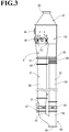
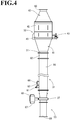
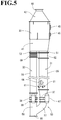
- the exhaust gas path 30 of each of the electricity-generating engines 25 includes a main path 31 extending to the funnel 4, a bypass path 32 branching off from a midway of the main path 31, and a combined casing (purification casing) 33 communicated with both of the main path 31 and the bypass path 32.
- a combined casing (purification casing) 33 communicated with both of the main path 31 and the bypass path 32.
- an exhaust gas purification system including components such as the main path 31, the bypass path 32, and the combined casing 33 is provided for each of the electricity-generating engines 25 in a one-to-one relation.
- the combined casing 33 is made of a heat-resistant metallic material and is shaped in a substantial cylinder (a prismatic cylinder, in the first illustrative example).
- the combined casing 33 is disposed upward of the third deck 15, on which the electricity-generating engines 25 are placed. In this configuration, the combined casing 33 is located in an upper part of the engine room 11 (on the second deck 14, which is an upper floor of the engine room 11).
- a NOx catalyst 34 and a slip processing catalyst 35 serving as a selective catalytic reduction device that facilitates reduction of NOx in an exhaust gas from the electricity-generating engine 25 are accommodated.
- the bypass path 32 is a path for causing the exhaust gas to make a detour not to allow the exhaust gas to pass through the NOx catalyst 34 and the slip processing catalyst 35.
- an exhaust gas outlet 42 i.e., a downstream side that is downstream of the slip processing catalyst 35 in an exhaust gas traveling direction; hereinafter, such a side is referred to simply as a downstream side
- the main path 31 and the bypass path 32 are merged with each other.
- the slip processing catalyst 35 may be omitted and the NOx catalyst 34 may be provided alone.
- a branched portion between the main path 31 and the bypass path 32 is located outside the combined casing 33.
- a main-side switching valve 37 and a bypass-side switching valve 38 are provided as a path-switching member for changing the exhaust gas traveling direction from the main path 31 to the bypass path 32, and vice versa.
- Each of the main-side switching valve 37 and the bypass-side switching valve 38 according to the present illustrative example is a single-acting switching valve.
- a pneumatic butterfly valve may be used as each of the main-side switching valve 37 and the bypass-side switching valve 38.
- the main-side switching valve 37 is provided on the side of an inlet of the main path 31 to the combined casing 33.
- the bypass-side switching valve 38 is provided on the side of an inlet of the bypass path 32 to the combined casing 33.
- the combined casing 33 is communicated with both of the main path 31 and the bypass path 32.
- the main path 31 side in the combined casing 33 accommodates the NOx catalyst 34 for facilitating reduction of NOx in the exhaust gas and the slip processing catalyst 35 for facilitating oxidation of an excessively supplied reducing agent (urea water or an aqueous urea solution; more specifically, ammonia resulting from hydrolysis), which are disposed in series in this order from an upstream side in the exhaust gas traveling direction (hereinafter, such a side is simply referred to as an upstream side).
- an excessively supplied reducing agent urea water or an aqueous urea solution; more specifically, ammonia resulting from hydrolysis
- the catalysts 34 and 35 each have a honeycomb structure including a large number of cells partitioned by partition walls being porous (capable of filtering), and contains a catalytic metal such as alumina, zirconia, vanadia/titania, or zeolite.
- the NOx catalyst 34 selectively reduces NOx in an exhaust gas by using, as a reducing agent, ammonia resulting from hydrolysis of urea water from a urea water injection nozzle 61 (described later). In this manner, NOx catalyst 34 purifies the exhaust gas having been sent to the main path 31 side in the combined casing 33.
- the slip processing catalyst 35 oxidizes unreacted (excess) ammonia flowed out of the NOx catalyst 34 to convert ammonia to nitrogen, which is harmless.
- the main path 31 and the bypass path 32 are disposed side by side in the combined casing 33.
- a partition plate 40 extending along the exhaust gas traveling direction is disposed in the combined casing 33.
- the interior of the combined casing 33 is partitioned into the main path 31 side and a bypass path 32 side (i.e., a part of the combined casing 33 corresponding to the bypass path 32).
- the NOx catalyst 34 and the slip processing catalyst 35 which are disposed in the main path 31 side, can be warmed up by the heat of the exhaust gas while the exhaust gas is passing through the bypass path 32.
- a part of an exhaust inlet 41 corresponding to the main path 31 side in the combined casing 33 has a tapered (conical) shape having a cross-sectional area becoming smaller toward the upstream side.
- a downstream end 400 of the partition plate 40 is extended, in the combined casing 33, to the exhaust gas outlet 42 located downstream of the slip processing catalyst 35, and has an opening 401. Consequently, the main path 31 side and the bypass path 32 side are merged with each other in the exhaust gas outlet 42 of the combined casing 33.
- the exhaust gas outlet 42 of the combined casing 33 has an outflow port (exhaust gas outflow port) 49 in a downstream end of the combined casing 33, and the outflow port 49 is communicated with an exhaust discharge pipe 60.
- the exhaust gas outlet 42 has a tapered (conical) shape having a cross-sectional area becoming smaller toward the outflow port 49, which is located on the downstream side.
- the outflow port 49 is located in the center of the downstream end of the combined casing 33. Namely, in the combined casing 33, the outflow port 49 is located in a position where the outflow port 49 overlaps the exhaust side of the main path 31.
- the downstream end 400 of the partition plate 40 is extended and is provided in a position where the downstream end 400 covers the outlet of the main path 31, and is fixed to the inner wall surface of the combined casing 33.
- the downstream end 400 of the partition plate 40 is provided as a reverse-flow prevention plate for preventing a phenomenon that the exhaust gas having flowed from the bypass path 32 into the exhaust gas outlet 42 enters the main path 31 (hereinafter, the downstream end 400 of the partition plate 40 is referred to as the reverse-flow prevention plate 400).
- the reverse-flow prevention plate 400 is extended from a position which is at a boundary between the main path 31 and the bypass path 32 and which is downstream of the slip processing catalyst 35 toward another position which is in the peripheral edge of the outflow port 49 and which is apart from the bypass path 32.
- the exhaust gas having passed through the main path 31 reaches the outflow port 49 of the exhaust gas outlet 42 through the opening 401 of the reverse-flow prevention plate 400. Then, the exhaust gas having been purified is discharged from the exhaust discharge pipe 60. Meanwhile, the exhaust gas having passed through the bypass path 32 is guided by the reverse-flow prevention plate 400, and reaches the outflow port 49 of the exhaust gas outlet 42.
- the inflow amount into the main path 31 (the amount of the exhaust gas reversely flowing to the main path 31) is reduced, and the exhaust gas is mostly discharged from the exhaust discharge pipe 60. Consequently, it is possible to reduce degradation of the NOx catalyst 34 and the slip processing catalyst 35 in the main path 31 while the bypass path 32 is in use.
- the combined casing 33 has a side surface provided with a plurality of injection nozzles 43 each serving as a gas jet.
- a compressed gas (air) from a gas supply source (not illustrated) is blown toward the NOx catalyst 34 and the slip processing catalyst 35.
- a gas supply source not illustrated
- a main-side inflow port and a bypass-side inflow port are provided adjacent to a front surface of the exhaust inlet 41 of the combined casing 33.
- the main-side inflow port is communicated with the main path 31 side in the combined casing 33, and the bypass-side inflow port is communicated with the bypass path 32 side in the combined casing 33.
- a main-side introduction pipe 51 communicated with the main-side inflow port and a bypass-side introduction pipe 52 communicated with the bypass-side inflow port are provided adjacent to an outer surface of a front part of the exhaust inlet 41 of the combined casing 33.
- the main-side introduction pipe 51 and the bypass-side introduction pipe 52 are communicated with a bifurcated pipe 53 via intermediate pipes 55 and 56, respectively.
- an inlet of the main-side intermediate pipe 55 is fastened to a main-side outlet 57 of the bifurcated pipe 53 via a flange.
- the other end of the main-side intermediate pipe 55 is communicated with the main-side intermediate pipe 51.
- An inlet of the bypass-side intermediate pipe 56 is fastened to a bypass-side outlet 58 of the bifurcated pipe 53 via a flange.
- An outlet of the bypass-side intermediate pipe 56 is fastened to the bypass-side introduction pipe 52 via an adjustable pipe 69 having a bellows structure for length adjustment.
- An inlet 59 of the bifurcated pipe 53 is connected to the upstream side of the main path 31 via a flange (detailed illustration thereof is omitted).
- the bifurcated pipe 53 corresponds to the branched portion between the main path 31 and the bypass path 32.
- the main-side switching valve 37 is disposed in the main-side outlet 57 of the bifurcated pipe 53, the main-side outlet 57 being communicated with the main path 31 side in the combined casing 33.
- the bypass-side switching valve 38 is disposed in the bypass-side outlet 58 of the bifurcated pipe 53, the bypass-side outlet 58 being communicated with the bypass path 32 side in the combined casing 33.
- the outflow port 49 is provided in a location which is adjacent to a rear surface of the exhaust gas outlet 42 of the combined casing 33 and which is close to the main path 31 side.
- the exhaust discharge pipe 60 communicated with the outflow port 49 is provided in a location adjacent to an outer surface of a rear part of the exhaust gas outlet 42 of the combined casing 33.
- the exhaust discharge pipe 60 is connected to the downstream side of the main path 31 via a flange.
- a urea water injection nozzle 61 for injecting urea water that is a reducing agent to an exhaust gas and an exhaust mixer 62 for mixing the exhaust gas and the urea water are disposed in this order from the upstream side.
- the main-side intermediate pipe 55 includes a plurality of (two, in the first illustrative example) urea water injection nozzles 61. In this configuration, the urea water injection nozzles 61 inject urea water in an atomized form into the main-side intermediate pipe 55.
- the exhaust mixer 62 is disposed between the main-side intermediate pipe 55 and the main-side introduction pipe 51.
- the exhaust mixer 62 is located downstream of the urea water injection nozzles 61, which are disposed in the main-side intermediate pipe 55, so that the exhaust mixer 62 is apart from the urea water injection nozzles 61 by a predetermined distance.
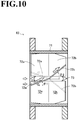
- the predetermined distance in this case is a distance necessary to hydrolyze, in the main-side intermediate pipe 55, urea water having been injected from the urea water injection nozzles 61 into ammonia. As illustrated in FIGs.
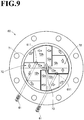
- the exhaust mixer 62 of the first illustrative example includes a mixer tube 71 having a tubular shape with an inner diameter identical to those of the main-side intermediate pipe 55 and the main-side introduction pipe 51, a plurality of (four, in the first illustrative example) mixing fins 72 provided to the inner periphery of the mixer tube 71, and an axis center body 73 located at the axis center of the mixer tube 71.
- the exhaust mixer 62 is configured to cause an exhaust gas and atomized urea water passing through the exhaust mixer 62 to swirl by the mixing fins 72 and the axis center body 73.
- the mixing fins 72 are members for turning a flow of an exhaust gas into a swirl flow, and are arranged radially from the center of the mixer tube 71 toward the inner peripheral surface of the mixer tube 71. In this configuration, the edge surfaces of the radially inner sides of the mixing fins 72 are fixed to the axis center body 73, whereas the edge surfaces of the radially outer sides of the mixing fins 72 are fixed to the inner peripheral surface of the mixer tube 71.
- the mixing fins 72 are located at equal angular intervals along a circumferential direction of the mixer tube 71 (i.e., located point-symmetrically around the axis center body 73). Note that the number of mixing fins 72 is not limited to four of the first illustrative example.
- Each of the mixing fins 72 has an upstream portion and a downstream portion that have respective predetermined angles relative to the exhaust gas traveling direction (i.e., the direction along the axis center of the mixer tube 71 and the like). Namely, each of the mixing fins 72 is bent in its midway along the exhaust gas traveling direction. In this configuration, each of the mixing fins 72 is bent such that an upstream fin plate 72a has an inclination angle ⁇ 1 relative to the exhaust gas traveling direction and a downstream fin plate 72b has an inclination angle ⁇ 2 relative to the exhaust gas traveling direction. The inclination angle ⁇ 2 of the downstream fin plate 72b is greater than the inclination angle ⁇ 1 of the upstream fin plate 72a.
- the inclination angles ⁇ 1 and ⁇ 2 of the fin plates 72a and 72b are set so that an angle on the downstream side is greater than an angle on the upstream side.
- the inclination angles ⁇ 1 and ⁇ 2 of the fin plates 72a and 72b are set so that the mixing fin has an angle becoming greater continuously or step-by-step from the upstream side toward the downstream side.
- the axis center body 73 which supports the edge surfaces of the radially inner sides of the mixing fins 72, has an upstream front end having a shape that is tapered (conical) toward its front end and has a cross-sectional area becoming smaller toward the upstream side.
- the axis center body 73 has a downstream base end having a shape that is tapered (conical) toward its rear end and has a cross-sectional area becoming smaller toward the downstream side. Consequently, an exhaust gas flowing to the axis center of the mixer tube 71 and/or its surroundings is guided toward the mixing fins 72 located radially outside, by the upstream front end, which has a tapered shape, of the axis center body 73.
- the exhaust mixer 62 is configured to include the axis center body 73 to which the mixing fins 72 are fixed.
- the exhaust mixer 62 may not include the axis center body 73.
- multiple support stays 73x (two support stays 73x, in the present illustrative example) each having a bar shape cross each other and are fixed to each other.
- the support stays 73x are disposed so that the intersection of the support stays 73x is aligned with the center of the mixer tube 71.
- Two mixing fins 72 are fixed to each of the support stays 73x, and the two mixing fins 72 are provided on opposite sides of the intersection of the support stays 73x.
- Each of the mixing fins 72 has an upstream front end that is an edge side extending from the center of the mixer tube 71 toward the inner peripheral surface of the mixer tube 71.
- the edge side extends toward the upstream side, and bends in its midway to extend parallel to an opening plane of the mixer tube 71.
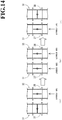
- the urea water injection nozzles 61 respectively have urea water injection ports 611 located in positions where the urea water injection ports 611 overlap corresponding ones of the mixing fins 72 in the exhaust mixer 62, which is located on the downstream side, when viewed in a cross section of the main path 31 (the main-side intermediate pipe 55).
- the urea water injection ports 611 of the urea water injection nozzles 61 are arranged at equal intervals (equal angular intervals) along a circumferential direction of the main path 31 (the main-side intermediate pipe 55).
- the number of urea water injection nozzles 61 corresponds to a divisor of the number of mixing fins 72.
- the urea water injection ports 611 of the urea water injection nozzles 61 are located in positions that coincide with the positions of corresponding ones of the mixing fins 72 of the exhaust mixer 62, along the circumferential direction of the main path 31 (the main-side intermediate pipe 55 and the mixer tube 71). Note that the number of urea water injection nozzles 61 is not limited to two of the first illustrative example.
- the main path 30 and the bypass path 32 in each exhaust gas path 30 are provided with the main-side switching valve 37 and the bypass-side switching valve 38, respectively (in the present illustrative example, three sets of switching valves, namely, six switching valves are provided).
- the main-side switching valve 37 and the bypass-side switching valve 38 serve as opening/closing members for opening and closing the main path 30 and the bypass path 32, respectively.
- the main-side switching valve 37 and the bypass-side switching valve 38 are configured such that, to select a path through which an exhaust gas passes, one of the main-side switching valve 37 and the bypass-side switching valve 38 is closed when the other is opened.
- the main-side switching valve 37 and the bypass-side switching valve 38 are configured to be opened and closed according to the conditions such as the emission control area.
- a path through which an exhaust gas passes can be appropriately selected merely by changing open/closed states of the main-side switching valve 37 and the bypass-side switching valve 38 depending on whether the purification treatment on the exhaust gas is necessary or not, e.g., depending on whether the ship is traveling in or outside an emission control area. This enables an efficient treatment on the exhaust gas.
- the above configuration enables to guide the exhaust gas to the bypass path 32 side, which is directly communicated with outside, while avoiding the exhaust gas passing through the NOx catalyst 34 and the slip processing catalyst 35. Consequently, it is possible to maintain the state with good exhaust efficiency, and thereby to avoid a reduction in outputs of the electricity-generating engines 25.
- this configuration can avoid exposure of the NOx catalyst 34 and the slip processing catalyst 35 to the exhaust gas, and therefore contributes to extension of the service lives of the NOx catalyst 34 and the slip processing catalyst 35.
- the main-side switching valve 37 and the bypass-side switching valve 38 are configured such that at least the bypass-side switching valve 38 in the bypass path 32 side is closed. Consequently, it is possible to easily and more reliably achieve prevention of a phenomenon that, while one electricity-generating engine 25 is stopped, an exhaust gas discharged from another engine reversely flows into the one electricity-generating engine 25.
- the main-side switching valve 37 and the bypass-side switching valve 38 are fluid-operated switching valves, and are maintained in an open state (normally open) while no fluid is supplied.
- a main-side valve driver 67 for performing a switching operation of the main-side switching valve 37 and a bypass-side valve driver 68 for performing a switching operation of the bypass-side switching valve 38 are provided.
- Each of the main-side valve driver 67 and the bypass-side valve driver 68 is a single-acting pneumatic cylinder.
- the main-side valve driver 67 is disposed adjacent to the outer periphery of the main-side intermediate pipe 55 and in parallel with the main-side intermediate pipe 55 along a longitudinal direction of the main-side intermediate pipe 55.
- the bypass-side valve driver 68 is disposed adjacent to the outer periphery of the bypass-side intermediate pipe 56 and in parallel with the bypass-side intermediate pipe 56 along a longitudinal direction of the bypass-side intermediate pipe 56.
- each of the valve driver 67 of the main-side switching valve 37 and the valve driver 68 of the bypass-side switching valve 38 is connected to a fluid supply source 81 via a fluid circulation pipe 80.
- the fluid supply source 81 is configured to supply air (or a nitrogen gas) that is a compressed fluid for actuating the valve drivers 67 and 68 (i.e., for actuating the main-side switching valve 37 and the bypass-side switching valve 38).
- a filter regulator 82 for switching between a fluid supply mode and a fluid-supply stop mode regarding supply of a fluid to a respective one of the valve drivers 67 and 68, and a flow-rate adjuster 84 including a close-side adjuster and an open-side adjuster are provided in this order from an upstream side.
- Each solenoid valve 83 operates based on the control information, and is configured to permit or stop supply of a compressed fluid to a corresponding one of the valve driver 67 of the switching valve 37 and the valve driver 68 of the switching valve 38.
- each of the valve drivers 67 and 68 is provided with a limit switch 85 for determining whether its corresponding solenoid valve 83 is in a fluid supply mode or in a fluid-supply stop mode.
- Each of the valve drivers 67 and 68 is connected to a silencer 86.
- Each of the solenoid valves 83 is connected to a silencer 87.
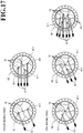
- a path through which the exhaust gas passes is switched from one to another in the following manner.
- the solenoid valves 83 in both of the main side and the bypass side enter a fluid-supply stop state, and accordingly fluid supply to the main-side switching valve 37 and the bypass-side switching valve 38 is stopped.
- the main-side switching valve 37 and the bypass-side switching valve 38 are normally-open switching valves, as described above. Therefore, once the fluid supply is stopped, the main-side switching valve 37 and the bypass-side switching valve 38 are driven by the valve drivers 67 and 68, and accordingly are opened. After that, one of the solenoid valves 83 on the side on which the exhaust gas is not to be allowed to pass through enters a fluid supply state, and accordingly the switching valve to which the fluid is supplied is closed.
- the main-side switching valve 37 and the bypass-side switching valve 38 operate to change from a state in which the main-side switching valve 37 is closed and the bypass-side switching valve 38 is opened (see FIG. 14(a) ) to a state in which both of the main-side switching valve 37 and the bypass-side switching valve 38 are opened (see FIG. 14(b) ) temporarily, and then to a state in which the bypass-side switching valve 38 is closed and the main-side switching valve 37 is opened (see FIG. 14(c) ).
- the exhaust gas passes through the main path 31. Specifically, an exhaust gas passes through the main-side outlet 57 of the bifurcated pipe 53, the main-side intermediate pipe 55, the exhaust mixer 62, the main-side introduction pipe 51, and the main-side inflow port 47, and enters the main path 31 side in the combined casing 33. Then, the exhaust gas passes through the NOx catalyst 34 and the slip processing catalyst 35, and thereby is subjected to a purification treatment.
- the exhaust gas containing urea water in an atomized form injected from the urea water injection nozzles 61 is guided to the exhaust mixer 62 through the main-side intermediate pipe 55.
- the upstream fin plate 72a of each mixing fin 72 changes the exhaust gas traveling direction to the direction of the inclination angle 01, and then the downstream fin plate 72b of the mixing fin 72 further changes the exhaust gas traveling direction to the direction of ⁇ 2. Consequently, the exhaust gas containing the urea water flows toward the inner peripheral surface of the mixer tube 71, and accordingly the exhaust gas travels in a circumferential direction along the inner peripheral surface of the mixer tube 71.
- the exhaust gas is caused to swirl in the part of the exhaust inlet 41 corresponding to the main path 31 side in the combined casing 33.
- the part of the exhaust inlet 41 corresponding to the main path 31 side in the combined casing 33 has a tapered (conical) shape having a cross-sectional area becoming smaller toward the upstream side. This increases the swirl diameter of the swirl flow of the exhaust gas. Consequently, the exhaust gas reaches the NOx catalyst 34 provided in the main path 31 side in the combined casing 33, while being mixed with the urea water more uniformly.
- the urea water injection nozzles 61 are inserted into the main-side intermediate pipe 55, and the urea water injection nozzles 611 at the tip ends of the urea water injection nozzles 61 are directed to the downstream side.
- the urea water injection ports 611 are arranged at equal intervals along the circumferential direction of the main-side intermediate pipe 55, and are disposed in positions where the urea water injection ports 611 overlap corresponding ones of the mixing fins 72 in the exhaust mixer 62 located on the downstream side. Consequently, when the urea water injection nozzles 61 inject urea water through the urea water injection ports 611 toward the downstream side, the urea water can be injected toward the mixing fins 72 of the exhaust mixer 62.
- the urea water can be injected in a diffused manner. Furthermore, the urea water having been injected comes in contact with the mixing fins 72, and thus the urea water is further dispersed. Consequently, the distribution amount of urea water in the exhaust mixer 62 can be made uniform. This increases the mixing efficiency of the exhaust gas and the urea water and reduces a temperature drop in a part of the exhaust mixer 62, thereby reducing occurrence of urea precipitation. Furthermore, since the diffusion efficiency of the urea water is increased, it is possible to reduce the distance between the urea water injection nozzles 61 and the exhaust mixer 62. Therefore, it is possible to use a main-side intermediate pipe 55 having a shorter length.
- the urea water injection ports 611 are disposed in positions where the urea water injection ports 611 overlap upstream tip ends of corresponding ones of the mixing fins 72 on respective straight lines along the exhaust gas traveling direction, and the urea water injection ports 611 inject urea water toward the upstream tip ends of the mixing fins 72.
- the urea water injected from the urea water injection nozzles 61 comes in contact with the side edges of the upstream tip ends of the mixing fins 72, and consequently the urea water is guided into the exhaust mixer 62 in a diffused manner. Consequently, the dispersion efficiency of the urea water in the exhaust mixer 62 can be increased, and hence the efficiency of purifying the exhaust gas can be increased.
- the urea water injection ports 611 of the urea water injection nozzles 61 are disposed in a center region between the center and the inner peripheral surface of the main path 61 (the main-side intermediate pipe 55). Namely, the urea water injection ports 611 are disposed in positions in which the urea water injection ports 611 overlap the upstream tip ends of corresponding ones of the mixing fins 71 and which are in a center region of the upstream tip ends of the mixing fins 72. With this configuration, the urea water having been injected from the urea water injection nozzles 61 is likely to be diffused uniformly in the main path 31. This makes it possible to reduce urea precipitation in the main path 31, the exhaust mixer 62, and/or other parts.
- the urea water injection ports 611 are disposed in positions where the urea water injection ports 611 overlap corresponding ones of the bent portions of the upstream tip ends of the mixing fins 72.
- the urea water injection ports 611 of the urea water injection nozzles 61 may be positioned to be away from the exhaust mixer 62 by different distances in the exhaust gas traveling direction. Namely, since the diffusion efficiency of the urea water is increased by the configuration including the plurality of urea water injection nozzles 61, it is possible to reduce the distance between the urea water injection nozzles 61 and the exhaust mixer 62. Therefore, the urea water injection nozzles 61 can be disposed in different positions in the exhaust gas traveling direction.
- the plurality of urea water injection nozzles 61 is inserted into the main-side intermediate pipe 55 in the same direction. This makes it possible to approach the urea water injection nozzles 61 in the same direction relative to the combined casing 33 during the maintenance.
- the number of urea water injection nozzles 61 is determined according to the number of mixing fins 72 of the exhaust mixer 62. Specifically, the number of urea water injection nozzles 61 corresponds to a divisor of the number of mixing fins 72 of the exhaust mixer 62, and the urea water injection ports 611 of the urea water injection nozzles 61 are arranged at equal intervals along the main path 31 (the main-side intermediate pipe 55). For example, in a case where the number of mixing fins 72 of the exhaust mixer 62 is four, two or four urea water injection nozzles 61 may be provided. Meanwhile, in a case where the number of mixing fins 72 of the exhaust mixer 62 is six, two, three, or six urea water injection nozzles 61 may be provided.
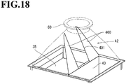
- the reverse-flow prevention plate 400 is the downstream end of the partition plate 40 that is extended, in the exhaust gas outlet 42 of the combined casing 33, from a region close to the downstream outlet of the main path 31 toward the peripheral edge of the outflow port 49.
- the outflow port 49 is disposed in a position where the outflow port 49 overlaps the main path 31.
- the reverse-flow prevention plate 400 is disposed downstream of the slip processing catalyst 35, and is extended obliquely from the partition plate 40 toward the peripheral edge of the outflow port 49.
- the peripheral edge of the reverse-flow prevention plate 400 is fixed to the inner wall surface of the combined casing 33.
- the exhaust gas having passed through the bypass path 32 is guided, along the reverse-flow prevention plate 400, to the exhaust discharge pipe 60 communicated with the outflow port 49, and is then discharged from the exhaust discharge pipe 60.
- the reverse-flow prevention plate 400 is located between the downstream outlet of the main path 31 and the outflow port 49, it is possible to reduce a phenomenon that the exhaust gas having passed through the bypass path 32 flows into the main path 31. Consequently, it is possible to reduce degradation of the NOx catalyst 34 and the slip processing catalyst 35, and thereby to keep a high purifying efficiency for a long period.
- the reverse-flow prevention plate 400 has, in its inner portion, an opening 401 through which the region close to the outlet of the main path 31 is communicated with the exhaust discharge pipe 60.
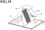
- the reverse-flow prevention plate 400 is made of two side-edge portions of the downstream end of the partition plate 40, the two side-edge portions being extended along the inner wall surface of the combined casing 33 toward the downstream side and having the opening 401 interposed between the two side-edge portions.
- the reverse-flow prevention plate 400 provided at a downstream end of a partition plate 40 has an opening 401 constituted by multiple holes.
- the reverse-flow prevention plate 400 is a perforated plate having the opening 401 constituted by multiple holes.
- the reverse-flow prevention plate 400 is located between a main path 31 and an exhaust discharge pipe 60. The peripheral edge (side edge and downstream-side edge) of the reverse-flow prevention plate 400 is fixed to the inner wall surface of a combined casing 33.
- the holes constituting the opening 401 are provided in two side-edge regions of the reverse-flow prevention plate 400.
- the holes constituting the opening are positioned at substantially equal intervals.
- the shape of the opening is not limited to a circle, but may have another shape such as a triangle or a rectangular.
- the exhaust gas having passed through the main path 31 is guided, through the holes constituting the opening 401, to an exhaust discharge pipe 60 communicated with an outflow port 49.
- the exhaust gas is then discharged from the exhaust discharge pipe 60.
- the exhaust gas having passed through a bypass path 32 is guided, along the reverse-flow prevention plate 400, to the exhaust discharge pipe 60 communicated with the outflow port 49.
- the exhaust gas is then discharged from the exhaust discharge pipe 60.
- the plurality of holes constituting the opening 401 is disposed in a part of the reverse-flow prevention plate 400.
- a plurality of holes constituting an opening 401 may be disposed over an entire surface of a reverse-flow prevention plate 40.
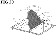
- a configuration of a reverse-flow prevention plate 400 in a combined casing 33 according to a third illustrative example of the present invention will be described below with reference to FIG. 21 .
- a downstream end of a partition plate 40 is terminated in an exhaust gas outlet 42 in the combined casing 33, the exhaust gas outlet 42 being located downstream of a slip processing catalyst 35.
- the downstream side of the slip processing catalyst 35 is covered with a reverse-flow prevention plate 400 that is perforated.
- the exhaust gas having passed through a main path 31 flows into the exhaust gas outlet 42 through holes constituting an opening 401, and is then discharged from an exhaust discharge pipe 60. Meanwhile, if a part of the exhaust gas flows into the main path 31 while the exhaust gas having passed through a bypass path 32 is flowing into the exhaust gas outlet 42, the reverse-flow prevention plate 400 blocks the part of the exhaust gas not to allow it to enter the slip processing catalyst 35.
- the reverse-flow prevention plate 400 blocks the part of the exhaust gas not to allow it to enter the slip processing catalyst 35.
- an outflow port 49 disposed in an exhaust gas outlet 42 of the combined casing 33 is positioned in a location close to a bypass path 32.
- the exhaust gas outlet 42 is tapered with its part corresponding to a main path 31 side being slanted so that a cross-sectional area of the exhaust gas outlet 42 becomes smaller toward the outflow port 49.
- the outflow port 49 is located in a position where the outflow port 49 overlaps the exhaust side of the bypass path 32.
- the reverse-flow prevention plate 400 having an opening 401 constituted by multiple holes is a downstream end of the partition plate 40 that is extended toward the peripheral edge of the outflow port 49 in the exhaust gas outlet 42 of the combined casing 33 without being bent.
- the outflow port 49 is disposed in a location that is in a downstream end of the combined casing 33 and is closer to the bypass path 32 side than the partition plate 40.
- the downstream end of the partition plate 40 is extended straightly along an exhaust gas traveling direction in the bypass path 32. This allows a downstream end of the reverse-flow prevention plate 400 to be in contact with a part of the inner wall surface of the downstream end of the combined casing 33, the part being closer to the main path 31 side than the outflow port 49.
- the exhaust gas passing through the bypass path 32 reaches the outflow port 49 without changing its exhaust gas traveling direction. Consequently, it is possible to reduce the amount of an exhaust gas flowing into the main path 31.
- the reverse-flow prevention plate 400 since the reverse-flow prevention plate 400 has a shape conformed to the exhaust gas traveling direction in the bypass path 32, it is possible to further block the flow of the exhaust gas toward the main path 31, and thereby to further reduce the amount of the exhaust gas flowing into the main path 31.
- the above configuration can reduce a phenomenon that the exhaust gas having passed through the bypass path 32 flows into the main path 31. This can prevent degradation of the NOx catalyst 34 and the slip processing catalyst 35, and can also reduce a decrease in the exhaust flow rate in a downstream outlet of the main path 31.
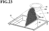
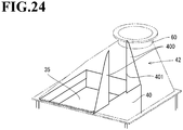
- the reverse-flow prevention plate 400 may have multiple holes 401 provided over an entire surface of the reverse-flow prevention plate 400 as illustrated in FIG. 23 or a hole 401 cut out in a center part of the reverse-flow prevention plate 400 from a downstream side in an exhaust gas traveling direction as illustrated in FIG. 24 , in order to reduce a pressure loss in the main path 31.
- the present invention is applied to an exhaust gas purification system to be provided in an exhaust gas path 30 of an electricity-generating engine 25.
- the present disclosure is not limited to this.
- the present disclosure may be applied to an exhaust gas purification system in an exhaust system of a main engine 21.
Landscapes
- Engineering & Computer Science (AREA)
- Chemical & Material Sciences (AREA)
- Chemical Kinetics & Catalysis (AREA)
- Combustion & Propulsion (AREA)
- Mechanical Engineering (AREA)
- General Engineering & Computer Science (AREA)
- Health & Medical Sciences (AREA)
- Toxicology (AREA)
- Materials Engineering (AREA)
- Biomedical Technology (AREA)
- Analytical Chemistry (AREA)
- General Chemical & Material Sciences (AREA)
- Oil, Petroleum & Natural Gas (AREA)
- Environmental & Geological Engineering (AREA)
- Ocean & Marine Engineering (AREA)
- Exhaust Gas After Treatment (AREA)
- Exhaust Gas Treatment By Means Of Catalyst (AREA)
Description
- The present invention relates to an exhaust gas purification device for removing harmful substances in an exhaust gas discharged from an engine that is to be mounted in a ship.
- Heretofore, ships such as tankers and transport ships include various auxiliary machineries, cargo-handling machines, illumination, air conditioners, and other devices that consume a huge amount of electrical power. In order to supply electricity to these electric systems, the ships include a diesel generator that is a combination of a diesel engine and an electricity generator for generating electrical power when the diesel engine is driven (see, e.g., Patent Literature 1 (hereinafter, PTL1)). It is known that the diesel engine is one of the engines having the highest energy efficiency among internal combustion engines, and the diesel engine emits an exhaust gas containing less carbon dioxide per unit output. Furthermore, the diesel engine can use a low-quality fuel such as heavy oil, which provides an economical advantage.
- The exhaust gas from the diesel engine contains carbon dioxide as well as a large amount of substances such as nitrogen oxide, sulfur oxide, and particulate matters. Especially, nitrogen oxide (hereinafter, referred to as NOx) is harmful to a human body and exhibits strong acidity, and is considered to be a cause of acid rain. Machines (such as ships) in which a diesel generator is driven emit a quite large amount of NOx, and therefore are considered to have a great negative effect on the global environment.
- As a post-treatment means for greatly purifying NOx, Selective Catalytic Reduction (hereinafter, referred to as SCR), which uses urea as a reducing agent, is commonly used (see, e.g.,
Patent Literatures 2 and 3 (hereinafter, PTL2 and PTL3)). SCR typically uses a honeycomb-structure NOx catalyst including a support being made of an oxide such as titanium oxide and carrying an active component such as V and/or Cr. When urea water serving as an aqueous reducing agent solution is sprayed to an upstream side of the NOx catalyst, the urea water is thermally decomposed upon heated by an exhaust gas and hydrolyzed, so that ammonia is produced. Ammonia acts on NOx as a reducing agent, and consequently NOx is decomposed into nitrogen and water, which are harmless. PTL2 suggests an exhaust gas purification device including a mixer (exhaust mixer) for mixing an exhaust gas and urea water in order to increase the efficiency of the reduction action of the NOx catalyst. - Considering the global environment, it is necessary to remove NOx in the exhaust gas as much as possible, and it is preferable to regulate NOx emission uniformly both in the high seas and in the territorial seas. Currently, however, along with application of a stricter emission regulation for diesel engines, NOx emission control areas are to be defined in the sea. As described above, the NOx catalyst has a honeycomb structure, and therefore may be clogged with soot and/or particles in the exhaust gas. In addition, the performance of the NOx catalyst may be degraded by sulfur components in the exhaust gas and/or products derived from the sulfur components. In order to extend the service life of the NOx catalyst as long as possible for the purpose of reducing the running cost and achieving compliance with the regulation in the emission control areas in the sea, it is desirable that the NOx catalyst not be exposed to an exhaust gas while the ship is traveling outside the emission control areas.
- In order to deal with this, PTL3 proposes an exhaust gas purification device including a purification casing which is disposed in an exhaust gas path of an engine and in which a NOx catalyst is accommodated. In addition, a bypass path causing an exhaust gas to make a detour not to allow the exhaust gas to pass through the NOx catalyst is disposed in the purification casing. In this configuration, an exhaust gas is sent to the NOx catalyst in the purification casing while the ship is traveling in the emission control area, whereas an exhaust gas is sent to the bypass path in the purification casing while the ship is traveling outside the emission control area.
-
- PTL1: Japanese Patent Application Laid-Open No.
2006-341742 - PTL2: Japanese Patent Application Laid-Open No.
2015-075042 - PTL3: Japanese Patent No.
5129400 -
WO 2015/064452 A1 relates to an exhaust gas purification system and ship using the same. The exhaust gas purification system is provided with the following: a main path that communicates with the outside; a bypass path that branches off from a midway section of the main path; and a combined casing that enables communication between the main path and the bypass path. Selective catalyst reduction devices are housed on the main path side in the combined casing. Path switching members that switch the movement direction of exhaust gas are disposed at a branching section between the main path and the bypass path. A reducing agent injection body is provided to the main path between the path switching member and the combined casing. -
JP H05 272334 A - In a configuration in which urea water injected by a urea water nozzle on an upstream side in an exhaust gas traveling direction is mixed with an exhaust gas by an exhaust mixer disposed on a downstream side in the exhaust gas traveling direction, a certain distance is necessary between the urea water nozzle and the exhaust mixer in order to adequately diffuse the urea water. If the urea water nozzle is too close to the exhaust mixer, the urea water is not adequately diffused and thus the urea water is concentrated locally in the exhaust mixer. This causes a temperature drop in a part of the exhaust mixer, leading to occurrence of urea precipitation. Furthermore, the inadequate diffusion of the urea water causes a decrease in the efficiency of the reduction (denitrification) action. Meanwhile, if a longer exhaust pipe is employed to achieve a distance between the urea water nozzle and the exhaust mixer, the size of the exhaust gas purification device is increased.
- In the configuration in which the bypass path is disposed in the purification casing, a merged chamber in which a main path including the NOx catalyst for carrying out the denitrification action and the bypass path are merged with each other is provided downstream of the purification casing. Thus, when an exhaust gas is caused to pass through the bypass path, the exhaust gas having passed through the bypass path may flow into the main path through the merged chamber in the purification casing, and the exhaust gas may reversely flow into the NOx catalyst. This may decrease the denitrification performance of the NOx catalyst.
- An aspect of the present invention has an object to provide an exhaust gas purification device for a ship that has been improved as a result of study of the circumstances described above.
- According to an aspect of the present invention, an exhaust gas purification device for a ship includes the features as defined in
claim 1. - The exhaust gas purification device described above is configured such that the reverse-flow prevention plate is a perforated plate having the opening constituted by multiple holes. In this configuration, the opening may be provided in a part of an inner portion of the reverse-flow prevention plate.
- The exhaust gas purification device described above is configured such that the exhaust gas outflow port is in a location close to the bypass path.
- The exhaust gas purification device described above may be configured such that a reducing agent injector of a reducing agent supply device for supplying a reducing agent to an exhaust gas is disposed in a part in the main path, the part being located upstream of the catalyst in the exhaust gas traveling direction, and cooled air is supplied to the reducing agent injector while the exhaust gas is passing through the bypass path.
- According to an aspect of the present invention, the exhaust gas having passed through the bypass path is guided to the exhaust gas outflow port along the reverse-flow prevention plate, and is then discharged from the purification casing. In addition, due to the reverse-flow prevention plate disposed between the downstream outlet of the main path and the exhaust gas outflow port, a phenomenon that the exhaust gas having passed through the bypass path flows into the main path can be reduced. Consequently, it is possible to reduce a decrease in the denitrification performance of the NOx catalyst in the purification casing.
- In addition, according to an aspect of the present invention, the reverse-flow prevention plate has, in its inner portion, an opening through which a region close to the outlet of the main path is communicated with the exhaust gas outflow port. With the opening configured as such, a pressure resistance caused by the reverse-flow prevention plate can be reduced in the region close to the outlet of the main path, and hence a pressure loss in the main path can be reduced.
-
- [
FIG. 1 ] A side view of an entire ship. - [
FIG. 2 ] A front sectional view taken along line II-II ofFIG. 1 . - [
FIG. 3 ] A front view of a combined casing. - [
FIG. 4 ] A side view of the combined casing. - [
FIG. 5 ] Aback view of the combined casing. - [
FIG. 6 ] A side view of the combined casing. - [
FIG. 7 ] A sectional view of an outlet of the combined casing. - [
FIG. 8 ] A perspective sectional view illustrating an internal configuration of an exhaust mixer. - [
FIG. 9 ] A front view of the exhaust mixer viewed from an upstream side in an exhaust gas traveling direction. - [
FIG. 10 ] Aside sectional view of the exhaust mixer. - [
FIG. 11 ] A side sectional view illustrating a flow of an exhaust gas from the exhaust mixer toward the combined casing. - [
FIG. 12 ] A perspective sectional view illustrating an internal configuration of an exhaust mixer having a different configuration. - [
FIG. 13 ] A circuit diagram of a fluid circulation pipe for which a switching valve is actuated. - [
FIG. 14 ] A schematic view illustrating how an exhaust gas path is switched from one to another. - [
FIG. 15 ] A front view illustrating a relation between urea water injection nozzles and an exhaust mixer viewed from an upstream side in an exhaust gas traveling direction. - [
FIG. 16 ] A side sectional view illustrating a relation between the urea water injection nozzles and the exhaust mixer. - [
FIG. 17 ] Schematic front views of other examples of arrangement of urea water injection nozzles and an exhaust mixer viewed from an upstream side in an exhaust gas traveling direction. - [
FIG. 18 ] A perspective view illustrating an internal configuration of a combined casing according to a first illustrative example. - [
FIG. 19 ] A perspective view illustrating an internal configuration of a combined casing according to a second illustrative example. - [
FIG. 20 ] A perspective view illustrating an internal configuration of another combined casing according to the second illustrative example. - [
FIG. 21 ] A perspective view illustrating an internal configuration of a combined casing according to a third illustrative example. - [
FIG. 22 ] A perspective view illustrating an internal configuration of a combined casing according to an embodiment of the present invention. - [
FIG. 23 ] A perspective view illustrating an internal configuration of another combined casing according to the embodiment. - [
FIG. 24 ] A perspective view illustrating an internal configuration of another combined casing according to the embodiment. - Illustrative examples, which do not form part of the invention as claimed, but are useful for understanding the invention, and an embodiment of the present invention will be described below with reference to the drawings illustrating cases where the present invention is applied to a diesel generator mounted in a ship.
- First, with reference to
FIG. 1 , a summary of aship 1 according to a first illustrative example will be described. Theship 1 according to the first illustrative example includes a ship'shull 2, a cabin 3 (bridge) provided, in the ship'shull 2, at a location close to the stern, a funnel 4 (chimney) placed rearward of the cabin 3, and a propeller 5 and a rudder 6 provided in a rear lower part of the ship'shull 2. In this configuration, askeg 8 is integrally provided to a part of thebottom 7 of the ship, the part being close to the stern. Theskeg 8 pivotally supports apropulsion shaft 9 configured to rotate the propeller 5. A ship'shold 10 is provided in a region of the ship'shull 2, the region including a part close to the bow and a middle part of the ship'shull 2. Anengine room 11 is provided, in the ship'shull 2, at a location close to the stern. - In the
engine room 11, a main engine 21 (a diesel engine, in the first illustrative example) that is a driving source of the propeller 5, aspeed reducer 22, and anelectricity generating unit 23 for supplying electricity to electric systems in the ship'shull 2 are disposed. The propeller 5 is rotated by rotation power transmitted from themain engine 21 via thespeed reducer 22. The interior of theengine room 11 is divided vertically
by anupper deck 13, asecond deck 14, athird deck 15, and aninner bottom plate 16. In the first illustrative example, themain engine 21 and thespeed reducer 22 are placed on theinner bottom plate 16, which is the lowermost floor of theengine room 11, and theelectricity generating unit 23 is placed on thethird deck 15, which is a middle floor of theengine room 11. The ship'shold 10 is partitioned into a plurality of sections (detailed illustration thereof is omitted). - As illustrated in
FIG. 2 , theelectricity generating unit 23 includes a plurality of (three, in the first illustrative example)diesel generators 24. Each of thediesel generator 24 is a combination of an electricity-generating engine 25 (a diesel engine, in the first illustrative example) and anelectricity generator 26 for generating electricity when the electricity-generatingengine 25 is driven. Basically, thediesel generator 24 is configured to operate efficiently according to an amount of electricity required in the ship'shull 2. For example, when the ship consumes a huge amount of electricity, e.g., when the ship leaves or enters a port,multiple diesel generators 24 are operated. Meanwhile, when the ship consumes relatively less electricity, e.g., while the ship is at anchor, arbitrary one or some of thediesel generators 24 are operated. Electricity generated as a result of operation of theelectricity generators 26 is supplied to the electric systems in the ship'shull 2. An electric power transducer is electrically connected to each electricity generator 26 (detailed illustration thereof is omitted). The electric power transducer is configured to detect electricity generated by theelectricity generator 26. - Next, with reference to
FIGs. 2 to 7 , an exhaust system of theelectricity generating unit 23 will be described. The electricity-generatingengines 25 are connected to respective intake paths (not illustrated) for taking air and respectiveexhaust gas paths 30 for discharging an exhaust gas. The air taken through each intake path is supplied to cylinders (cylinders on the intake stroke) in its respective electricity-generatingengine 25. Upon completion of the compression stroke in the cylinders, fuel sucked from a fuel tank is sent, under pressure, into respective combustion chambers in the cylinders by fuel injection devices. Then, following self-ignition combustion of an air-fuel mixture, the expansion stroke takes place in the combustion chambers. - The
exhaust gas paths 30 of the electricity-generatingengines 25 extend to thefunnel 4 to be directly communicated with outside. As described above, since the number of electricity-generatingengines 25 is three, the number ofexhaust gas paths 30 is three. Theexhaust gas path 30 of each of the electricity-generatingengines 25 includes amain path 31 extending to thefunnel 4, abypass path 32 branching off from a midway of themain path 31, and a combined casing (purification casing) 33 communicated with both of themain path 31 and thebypass path 32. Namely, in the first illustrative example, multiple electricity-generatingengines 25 are provided, and an exhaust gas purification system including components such as themain path 31, thebypass path 32, and the combinedcasing 33 is provided for each of the electricity-generatingengines 25 in a one-to-one relation. - The combined
casing 33 is made of a heat-resistant metallic material and is shaped in a substantial cylinder (a prismatic cylinder, in the first illustrative example).
The combinedcasing 33 is disposed upward of thethird deck 15, on which the electricity-generatingengines 25 are placed. In this configuration, the combinedcasing 33 is located in an upper part of the engine room 11 (on thesecond deck 14, which is an upper floor of the engine room 11). In a part of the combinedcasing 33 corresponding to the main path 31 (hereinafter, such a part is referred to as amain path 31 side), aNOx catalyst 34 and a slip processing catalyst 35 (described in detail later) serving as a selective catalytic reduction device that facilitates reduction of NOx in an exhaust gas from the electricity-generatingengine 25 are accommodated. Thebypass path 32 is a path for causing the exhaust gas to make a detour not to allow the exhaust gas to pass through theNOx catalyst 34 and theslip processing catalyst 35. In an exhaust gas outlet 42 (i.e., a downstream side that is downstream of theslip processing catalyst 35 in an exhaust gas traveling direction; hereinafter, such a side is referred to simply as a downstream side) of the combinedcasing 33, themain path 31 and thebypass path 32 are merged with each other. Note that, as the selective catalytic reduction device, theslip processing catalyst 35 may be omitted and theNOx catalyst 34 may be provided alone. - A branched portion between the
main path 31 and thebypass path 32 is located outside the combinedcasing 33. In the branch, a main-side switching valve 37 and a bypass-side switching valve 38, each of which is a fluid-operated switching valve, are provided as a path-switching member for changing the exhaust gas traveling direction from themain path 31 to thebypass path 32, and vice versa. Each of the main-side switching valve 37 and the bypass-side switching valve 38 according to the present illustrative example is a single-acting switching valve. As one example of the fluid-operated, single-acting switching valve, a pneumatic butterfly valve may be used as each of the main-side switching valve 37 and the bypass-side switching valve 38. The main-side switching valve 37 is provided on the side of an inlet of themain path 31 to the combinedcasing 33. The bypass-side switching valve 38 is provided on the side of an inlet of thebypass path 32 to the combinedcasing 33. - Next, with reference to
FIGs. 3 to 7 , a configuration of the combinedcasing 33 will be described. As described above, the combinedcasing 33 is communicated with both of themain path 31 and thebypass path 32. Themain path 31 side in the combinedcasing 33 accommodates theNOx catalyst 34 for facilitating reduction of NOx in the exhaust gas and theslip processing catalyst 35 for facilitating oxidation of an excessively supplied reducing agent (urea water or an aqueous urea solution; more specifically, ammonia resulting from hydrolysis), which are disposed in series in this order from an upstream side in the exhaust gas traveling direction (hereinafter, such a side is simply referred to as an upstream side). Thecatalysts - The
NOx catalyst 34 selectively reduces NOx in an exhaust gas by using, as a reducing agent, ammonia resulting from hydrolysis of urea water from a urea water injection nozzle 61 (described later). In this manner,NOx catalyst 34 purifies the exhaust gas having been sent to themain path 31 side in the combinedcasing 33. Theslip processing catalyst 35 oxidizes unreacted (excess) ammonia flowed out of theNOx catalyst 34 to convert ammonia to nitrogen, which is harmless. During this, in themain path 31 side in the combinedcasing 33, the reactions expressed by the following formulae occur:
(NH2)2CO + H2O -> 2NH3 + CO2 (hydrolysis)
NO + NO2 + 2NH3 -> 2N2 + 3H2O (reaction in NOx catalyst 34)
4NH3 + 3O2 -> 2N2 + 6H2O (reaction in slip processing catalyst 35)
- As illustrated in detail in
FIG. 7 , themain path 31 and thebypass path 32 are disposed side by side in the combinedcasing 33. In this configuration, apartition plate 40 extending along the exhaust gas traveling direction is disposed in the combinedcasing 33. By thepartition plate 40 thus provided, the interior of the combinedcasing 33 is partitioned into themain path 31 side and abypass path 32 side (i.e., a part of the combinedcasing 33 corresponding to the bypass path 32). In the configuration in which the interior of the combinedcasing 33 is partitioned by thepartition plate 40, theNOx catalyst 34 and theslip processing catalyst 35, which are disposed in themain path 31 side, can be warmed up by the heat of the exhaust gas while the exhaust gas is passing through thebypass path 32. Thus, it is possible to warm up theNOx catalyst 34 and theslip processing catalyst 35 all the time regardless of whether the exhaust gas is to be purified or not. In the case where the exhaust gas passes through themain path 31, this configuration contributes to shortening of the warming-up period, and may even eliminate the need for the warming-up depending on the circumstances. - A part of an
exhaust inlet 41 corresponding to themain path 31 side in the combinedcasing 33 has a tapered (conical) shape having a cross-sectional area becoming smaller toward the upstream side. Meanwhile, adownstream end 400 of thepartition plate 40 is extended, in the combinedcasing 33, to theexhaust gas outlet 42 located downstream of theslip processing catalyst 35, and has anopening 401. Consequently, themain path 31 side and thebypass path 32 side are merged with each other in theexhaust gas outlet 42 of the combinedcasing 33. - The
exhaust gas outlet 42 of the combinedcasing 33 has an outflow port (exhaust gas outflow port) 49 in a downstream end of the combinedcasing 33, and theoutflow port 49 is communicated with anexhaust discharge pipe 60. Theexhaust gas outlet 42 has a tapered (conical) shape having a cross-sectional area becoming smaller toward theoutflow port 49, which is located on the downstream side. Theoutflow port 49 is located in the center of the downstream end of the combinedcasing 33. Namely, in the combinedcasing 33, theoutflow port 49 is located in a position where theoutflow port 49 overlaps the exhaust side of themain path 31. - The
downstream end 400 of thepartition plate 40 is extended and is provided in a position where thedownstream end 400 covers the outlet of themain path 31, and is fixed to the inner wall surface of the combinedcasing 33. Thedownstream end 400 of thepartition plate 40 is provided as a reverse-flow prevention plate for preventing a phenomenon that the exhaust gas having flowed from thebypass path 32 into theexhaust gas outlet 42 enters the main path 31 (hereinafter, thedownstream end 400 of thepartition plate 40 is referred to as the reverse-flow prevention plate 400). The reverse-flow prevention plate 400 is extended from a position which is at a boundary between themain path 31 and thebypass path 32 and which is downstream of theslip processing catalyst 35 toward another position which is in the peripheral edge of theoutflow port 49 and which is apart from thebypass path 32. By theopening 401 provided in the reverse-flow prevention plate 400, themain path 31 side and thebypass path 32 side are merged with each other in theexhaust gas outlet 42. - The exhaust gas having passed through the
main path 31 reaches theoutflow port 49 of theexhaust gas outlet 42 through theopening 401 of the reverse-flow prevention plate 400. Then, the exhaust gas having been purified is discharged from theexhaust discharge pipe 60. Meanwhile, the exhaust gas having passed through thebypass path 32 is guided by the reverse-flow prevention plate 400, and reaches theoutflow port 49 of theexhaust gas outlet 42. Thus, the inflow amount into the main path 31 (the amount of the exhaust gas reversely flowing to the main path 31) is reduced, and the exhaust gas is mostly discharged from theexhaust discharge pipe 60. Consequently, it is possible to reduce degradation of theNOx catalyst 34 and theslip processing catalyst 35 in themain path 31 while thebypass path 32 is in use. - The combined
casing 33 has a side surface provided with a plurality ofinjection nozzles 43 each serving as a gas jet. By theinjection nozzles 43, a compressed gas (air) from a gas supply source (not illustrated) is blown toward theNOx catalyst 34 and theslip processing catalyst 35. By the action of theinjection nozzles 43, it is possible to forcibly remove soot particles accumulated in themain path 31 side in the combinedcasing 33 while themain path 31 side is in use. - A main-side inflow port and a bypass-side inflow port are provided adjacent to a front surface of the
exhaust inlet 41 of the combinedcasing 33. The main-side inflow port is communicated with themain path 31 side in the combinedcasing 33, and the bypass-side inflow port is communicated with thebypass path 32 side in the combinedcasing 33. A main-side introduction pipe 51 communicated with the main-side inflow port and a bypass-side introduction pipe 52 communicated with the bypass-side inflow port are provided adjacent to an outer surface of a front part of theexhaust inlet 41 of the combinedcasing 33. The main-side introduction pipe 51 and the bypass-side introduction pipe 52 are communicated with abifurcated pipe 53 viaintermediate pipes intermediate pipe 55 is fastened to a main-side outlet 57 of thebifurcated pipe 53 via a flange. The other end of the main-sideintermediate pipe 55 is communicated with the main-sideintermediate pipe 51. An inlet of the bypass-sideintermediate pipe 56 is fastened to a bypass-side outlet 58 of thebifurcated pipe 53 via a flange. An outlet of the bypass-sideintermediate pipe 56 is fastened to the bypass-side introduction pipe 52 via anadjustable pipe 69 having a bellows structure for length adjustment. - An
inlet 59 of thebifurcated pipe 53 is connected to the upstream side of themain path 31 via a flange (detailed illustration thereof is omitted). Thebifurcated pipe 53 corresponds to the branched portion between themain path 31 and thebypass path 32. The main-side switching valve 37 is disposed in the main-side outlet 57 of thebifurcated pipe 53, the main-side outlet 57 being communicated with themain path 31 side in the combinedcasing 33. The bypass-side switching valve 38 is disposed in the bypass-side outlet 58 of thebifurcated pipe 53, the bypass-side outlet 58 being communicated with thebypass path 32 side in the combinedcasing 33. Theoutflow port 49 is provided in a location which is adjacent to a rear surface of theexhaust gas outlet 42 of the combinedcasing 33 and which is close to themain path 31 side. Theexhaust discharge pipe 60 communicated with theoutflow port 49 is provided in a location adjacent to an outer surface of a rear part of theexhaust gas outlet 42 of the combinedcasing 33. Theexhaust discharge pipe 60 is connected to the downstream side of themain path 31 via a flange. - In a space of the
main path 31 between the main-side switching valve 37 and the main-side introduction pipe 51 connected to the combinedcasing 33, a ureawater injection nozzle 61 for injecting urea water that is a reducing agent to an exhaust gas and anexhaust mixer 62 for mixing the exhaust gas and the urea water are disposed in this order from the upstream side. The main-sideintermediate pipe 55 includes a plurality of (two, in the first illustrative example) ureawater injection nozzles 61. In this configuration, the ureawater injection nozzles 61 inject urea water in an atomized form into the main-sideintermediate pipe 55. - The
exhaust mixer 62 is disposed between the main-sideintermediate pipe 55 and the main-side introduction pipe 51. Theexhaust mixer 62 is located downstream of the ureawater injection nozzles 61, which are disposed in the main-sideintermediate pipe 55, so that theexhaust mixer 62 is apart from the ureawater injection nozzles 61 by a predetermined distance. The predetermined distance in this case is a distance necessary to hydrolyze, in the main-sideintermediate pipe 55, urea water having been injected from the ureawater injection nozzles 61 into ammonia. As illustrated inFIGs. 8 to 11 , theexhaust mixer 62 of the first illustrative example includes amixer tube 71 having a tubular shape with an inner diameter identical to those of the main-sideintermediate pipe 55 and the main-side introduction pipe 51, a plurality of (four, in the first illustrative example) mixingfins 72 provided to the inner periphery of themixer tube 71, and anaxis center body 73 located at the axis center of themixer tube 71. Theexhaust mixer 62 is configured to cause an exhaust gas and atomized urea water passing through theexhaust mixer 62 to swirl by the mixingfins 72 and theaxis center body 73. - The mixing
fins 72 are members for turning a flow of an exhaust gas into a swirl flow, and are arranged radially from the center of themixer tube 71 toward the inner peripheral surface of themixer tube 71. In this configuration, the edge surfaces of the radially inner sides of the mixingfins 72 are fixed to theaxis center body 73, whereas the edge surfaces of the radially outer sides of the mixingfins 72 are fixed to the inner peripheral surface of themixer tube 71. The mixingfins 72 are located at equal angular intervals along a circumferential direction of the mixer tube 71 (i.e., located point-symmetrically around the axis center body 73). Note that the number of mixingfins 72 is not limited to four of the first illustrative example. - Each of the mixing
fins 72 has an upstream portion and a downstream portion that have respective predetermined angles relative to the exhaust gas traveling direction (i.e., the direction along the axis center of themixer tube 71 and the like). Namely, each of the mixingfins 72 is bent in its midway along the exhaust gas traveling direction. In this configuration, each of the mixingfins 72 is bent such that anupstream fin plate 72a has an inclination angle θ1 relative to the exhaust gas traveling direction and adownstream fin plate 72b has an inclination angle θ2 relative to the exhaust gas traveling direction. The inclination angle θ2 of thedownstream fin plate 72b is greater than the inclination angle θ1 of theupstream fin plate 72a. Namely, the inclination angles θ1 and θ2 of thefin plates fin plates - The
axis center body 73, which supports the edge surfaces of the radially inner sides of the mixingfins 72, has an upstream front end having a shape that is tapered (conical) toward its front end and has a cross-sectional area becoming smaller toward the upstream side. In addition, theaxis center body 73 has a downstream base end having a shape that is tapered (conical) toward its rear end and has a cross-sectional area becoming smaller toward the downstream side. Consequently, an exhaust gas flowing to the axis center of themixer tube 71 and/or its surroundings is guided toward the mixingfins 72 located radially outside, by the upstream front end, which has a tapered shape, of theaxis center body 73. - In the present embodiment, the
exhaust mixer 62 is configured to include theaxis center body 73 to which the mixingfins 72 are fixed. Alternatively, as illustrated inFIG. 12 , theexhaust mixer 62 may not include theaxis center body 73. Specifically, multiple support stays 73x (two support stays 73x, in the present illustrative example) each having a bar shape cross each other and are fixed to each other. In addition, the support stays 73x are disposed so that the intersection of the support stays 73x is aligned with the center of themixer tube 71. Two mixingfins 72 are fixed to each of the support stays 73x, and the two mixingfins 72 are provided on opposite sides of the intersection of the support stays 73x. Each of the mixingfins 72 has an upstream front end that is an edge side extending from the center of themixer tube 71 toward the inner peripheral surface of themixer tube 71. The edge side extends toward the upstream side, and bends in its midway to extend parallel to an opening plane of themixer tube 71. - The urea
water injection nozzles 61 respectively have ureawater injection ports 611 located in positions where the ureawater injection ports 611 overlap corresponding ones of the mixingfins 72 in theexhaust mixer 62, which is located on the downstream side, when viewed in a cross section of the main path 31 (the main-side intermediate pipe 55). The ureawater injection ports 611 of the ureawater injection nozzles 61 are arranged at equal intervals (equal angular intervals) along a circumferential direction of the main path 31 (the main-side intermediate pipe 55). The number of ureawater injection nozzles 61 corresponds to a divisor of the number of mixingfins 72. The ureawater injection ports 611 of the ureawater injection nozzles 61 are located in positions that coincide with the positions of corresponding ones of the mixingfins 72 of theexhaust mixer 62, along the circumferential direction of the main path 31 (the main-sideintermediate pipe 55 and the mixer tube 71). Note that the number of ureawater injection nozzles 61 is not limited to two of the first illustrative example. - The
main path 30 and thebypass path 32 in eachexhaust gas path 30 are provided with the main-side switching valve 37 and the bypass-side switching valve 38, respectively (in the present illustrative example, three sets of switching valves, namely, six switching valves are provided). The main-side switching valve 37 and the bypass-side switching valve 38 serve as opening/closing members for opening and closing themain path 30 and thebypass path 32, respectively. The main-side switching valve 37 and the bypass-side switching valve 38 are configured such that, to select a path through which an exhaust gas passes, one of the main-side switching valve 37 and the bypass-side switching valve 38 is closed when the other is opened. In addition, the main-side switching valve 37 and the bypass-side switching valve 38 are configured to be opened and closed according to the conditions such as the emission control area. - In a state where the bypass-
side switching valve 38 is closed and the main-side switching valve 37 is opened, during the exhaust stroke after the expansion stroke, an exhaust gas supplied from each of the multiple electricity-generatingengines 25 to its correspondingmain path 31 passes through themain path 31 and then through theNOx catalyst 34 and theslip processing catalyst 35, and thereby is subjected to a purification treatment. Then, the exhaust gas is discharged outside theship 1. Meanwhile, in a state where the main-side switching valve 37 is closed and the bypass-side switching valve 38 is opened, an exhaust gas passes through the corresponding bypass path 32 (without passing through theNOx catalyst 34 and the slip processing catalyst 35), so that the exhaust gas is directly discharged outside theship 1. - Thus, with the configuration in which the
main path 31 and thebypass path 32 in eachexhaust gas path 30 are respectively provided with the main-side switching valve 37 and the bypass-side switching valve 38 serving as the opening/closing members for opening and closing thepaths side switching valve 37 and the bypass-side switching valve 38 depending on whether the purification treatment on the exhaust gas is necessary or not, e.g., depending on whether the ship is traveling in or outside an emission control area. This enables an efficient treatment on the exhaust gas. Furthermore, for example, in a case where the purification treatment on the exhaust gas is not necessary, the above configuration enables to guide the exhaust gas to thebypass path 32 side, which is directly communicated with outside, while avoiding the exhaust gas passing through theNOx catalyst 34 and theslip processing catalyst 35. Consequently, it is possible to maintain the state with good exhaust efficiency, and thereby to avoid a reduction in outputs of the electricity-generatingengines 25. Moreover, in the case where the purification treatment on the exhaust gas is not necessary, this configuration can avoid exposure of theNOx catalyst 34 and theslip processing catalyst 35 to the exhaust gas, and therefore contributes to extension of the service lives of theNOx catalyst 34 and theslip processing catalyst 35. - For a situation in which the electricity-generating
engine 25 is stopped, the main-side switching valve 37 and the bypass-side switching valve 38 are configured such that at least the bypass-side switching valve 38 in thebypass path 32 side is closed. Consequently, it is possible to easily and more reliably achieve prevention of a phenomenon that, while one electricity-generatingengine 25 is stopped, an exhaust gas discharged from another engine reversely flows into the one electricity-generatingengine 25. - As described above, the main-
side switching valve 37 and the bypass-side switching valve 38 are fluid-operated switching valves, and are maintained in an open state (normally open) while no fluid is supplied. In addition, a main-side valve driver 67 for performing a switching operation of the main-side switching valve 37 and a bypass-side valve driver 68 for performing a switching operation of the bypass-side switching valve 38 are provided. Each of the main-side valve driver 67 and the bypass-side valve driver 68 is a single-acting pneumatic cylinder. The main-side valve driver 67 is disposed adjacent to the outer periphery of the main-sideintermediate pipe 55 and in parallel with the main-sideintermediate pipe 55 along a longitudinal direction of the main-sideintermediate pipe 55. The bypass-side valve driver 68 is disposed adjacent to the outer periphery of the bypass-sideintermediate pipe 56 and in parallel with the bypass-sideintermediate pipe 56 along a longitudinal direction of the bypass-sideintermediate pipe 56. - As illustrated in
FIG. 13 , each of thevalve driver 67 of the main-side switching valve 37 and thevalve driver 68 of the bypass-side switching valve 38 is connected to afluid supply source 81 via afluid circulation pipe 80. Thefluid supply source 81 is configured to supply air (or a nitrogen gas) that is a compressed fluid for actuating thevalve drivers 67 and 68 (i.e., for actuating the main-side switching valve 37 and the bypass-side switching valve 38). In a midway of each of thefluid circulation pipes 80 on the main side and the bypass side, afilter regulator 82, asolenoid valve 83 for switching between a fluid supply mode and a fluid-supply stop mode regarding supply of a fluid to a respective one of thevalve drivers rate adjuster 84 including a close-side adjuster and an open-side adjuster are provided in this order from an upstream side. Eachsolenoid valve 83 operates based on the control information, and is configured to permit or stop supply of a compressed fluid to a corresponding one of thevalve driver 67 of the switchingvalve 37 and thevalve driver 68 of the switchingvalve 38. In addition, each of thevalve drivers limit switch 85 for determining whether its correspondingsolenoid valve 83 is in a fluid supply mode or in a fluid-supply stop mode. Each of thevalve drivers silencer 86. Each of thesolenoid valves 83 is connected to asilencer 87. - A path through which the exhaust gas passes is switched from one to another in the following manner. The
solenoid valves 83 in both of the main side and the bypass side enter a fluid-supply stop state, and accordingly fluid supply to the main-side switching valve 37 and the bypass-side switching valve 38 is stopped. The main-side switching valve 37 and the bypass-side switching valve 38 are normally-open switching valves, as described above. Therefore, once the fluid supply is stopped, the main-side switching valve 37 and the bypass-side switching valve 38 are driven by thevalve drivers solenoid valves 83 on the side on which the exhaust gas is not to be allowed to pass through enters a fluid supply state, and accordingly the switching valve to which the fluid is supplied is closed. Meanwhile, the other of thesolenoid valves 83 on the side on which the exhaust gas is to be allowed to pass through is still in the fluid-supply stop state, and the switching valve remains open. In this manner, a path through which the exhaust gas passes is switched from one to another. As one example, the main-side switching valve 37 and the bypass-side switching valve 38 operate to change from a state in which the main-side switching valve 37 is closed and the bypass-side switching valve 38 is opened (seeFIG. 14(a) ) to a state in which both of the main-side switching valve 37 and the bypass-side switching valve 38 are opened (seeFIG. 14(b) ) temporarily, and then to a state in which the bypass-side switching valve 38 is closed and the main-side switching valve 37 is opened (seeFIG. 14(c) ). - In the configuration described above, in the case where the main-
side switching valve 37 is opened and the bypass-side switching valve 38 is closed, the exhaust gas passes through themain path 31. Specifically, an exhaust gas passes through the main-side outlet 57 of thebifurcated pipe 53, the main-sideintermediate pipe 55, theexhaust mixer 62, the main-side introduction pipe 51, and the main-side inflow port 47, and enters themain path 31 side in the combinedcasing 33. Then, the exhaust gas passes through theNOx catalyst 34 and theslip processing catalyst 35, and thereby is subjected to a purification treatment. - In this case, the exhaust gas containing urea water in an atomized form injected from the urea
water injection nozzles 61 is guided to theexhaust mixer 62 through the main-sideintermediate pipe 55. Theupstream fin plate 72a of each mixingfin 72 changes the exhaust gas traveling direction to the direction of theinclination angle 01, and then thedownstream fin plate 72b of the mixingfin 72 further changes the exhaust gas traveling direction to the direction of θ2. Consequently, the exhaust gas containing the urea water flows toward the inner peripheral surface of themixer tube 71, and accordingly the exhaust gas travels in a circumferential direction along the inner peripheral surface of themixer tube 71. As a result, the exhaust gas is caused to swirl in the part of theexhaust inlet 41 corresponding to themain path 31 side in the combinedcasing 33. Thus, the exhaust gas and the urea water are mixed smoothly and efficiently. The part of theexhaust inlet 41 corresponding to themain path 31 side in the combinedcasing 33 has a tapered (conical) shape having a cross-sectional area becoming smaller toward the upstream side. This increases the swirl diameter of the swirl flow of the exhaust gas. Consequently, the exhaust gas reaches theNOx catalyst 34 provided in themain path 31 side in the combinedcasing 33, while being mixed with the urea water more uniformly. - As illustrated in
FIG. 9 , the ureawater injection nozzles 61 are inserted into the main-sideintermediate pipe 55, and the ureawater injection nozzles 611 at the tip ends of the ureawater injection nozzles 61 are directed to the downstream side. The ureawater injection ports 611 are arranged at equal intervals along the circumferential direction of the main-sideintermediate pipe 55, and are disposed in positions where the ureawater injection ports 611 overlap corresponding ones of the mixingfins 72 in theexhaust mixer 62 located on the downstream side. Consequently, when the ureawater injection nozzles 61 inject urea water through the ureawater injection ports 611 toward the downstream side, the urea water can be injected toward the mixingfins 72 of theexhaust mixer 62. - Thus, by injecting urea water by the plurality of urea
water injection nozzles 61 dispersedly, the urea water can be injected in a diffused manner. Furthermore, the urea water having been injected comes in contact with the mixingfins 72, and thus the urea water is further dispersed. Consequently, the distribution amount of urea water in theexhaust mixer 62 can be made uniform. This increases the mixing efficiency of the exhaust gas and the urea water and reduces a temperature drop in a part of theexhaust mixer 62, thereby reducing occurrence of urea precipitation. Furthermore, since the diffusion efficiency of the urea water is increased, it is possible to reduce the distance between the ureawater injection nozzles 61 and theexhaust mixer 62. Therefore, it is possible to use a main-sideintermediate pipe 55 having a shorter length. - The urea
water injection ports 611 are disposed in positions where the ureawater injection ports 611 overlap upstream tip ends of corresponding ones of the mixingfins 72 on respective straight lines along the exhaust gas traveling direction, and the ureawater injection ports 611 inject urea water toward the upstream tip ends of the mixingfins 72. Thus, the urea water injected from the ureawater injection nozzles 61 comes in contact with the side edges of the upstream tip ends of the mixingfins 72, and consequently the urea water is guided into theexhaust mixer 62 in a diffused manner. Consequently, the dispersion efficiency of the urea water in theexhaust mixer 62 can be increased, and hence the efficiency of purifying the exhaust gas can be increased. - The urea
water injection ports 611 of the ureawater injection nozzles 61 are disposed in a center region between the center and the inner peripheral surface of the main path 61 (the main-side intermediate pipe 55). Namely, the ureawater injection ports 611 are disposed in positions in which the ureawater injection ports 611 overlap the upstream tip ends of corresponding ones of the mixingfins 71 and which are in a center region of the upstream tip ends of the mixingfins 72. With this configuration, the urea water having been injected from the ureawater injection nozzles 61 is likely to be diffused uniformly in themain path 31. This makes it possible to reduce urea precipitation in themain path 31, theexhaust mixer 62, and/or other parts. In addition, with reference toFIG. 15 , in theexhaust mixer 62 configured as illustrated inFIG. 12 , the ureawater injection ports 611 are disposed in positions where the ureawater injection ports 611 overlap corresponding ones of the bent portions of the upstream tip ends of the mixingfins 72. - As illustrated in
FIG. 16 , the ureawater injection ports 611 of the ureawater injection nozzles 61 may be positioned to be away from theexhaust mixer 62 by different distances in the exhaust gas traveling direction. Namely, since the diffusion efficiency of the urea water is increased by the configuration including the plurality of ureawater injection nozzles 61, it is possible to reduce the distance between the ureawater injection nozzles 61 and theexhaust mixer 62. Therefore, the ureawater injection nozzles 61 can be disposed in different positions in the exhaust gas traveling direction. In addition, the plurality of ureawater injection nozzles 61 is inserted into the main-sideintermediate pipe 55 in the same direction. This makes it possible to approach the ureawater injection nozzles 61 in the same direction relative to the combinedcasing 33 during the maintenance. - As illustrated in
FIG. 17 , the number of ureawater injection nozzles 61 is determined according to the number of mixingfins 72 of theexhaust mixer 62. Specifically, the number of ureawater injection nozzles 61 corresponds to a divisor of the number of mixingfins 72 of theexhaust mixer 62, and the ureawater injection ports 611 of the ureawater injection nozzles 61 are arranged at equal intervals along the main path 31 (the main-side intermediate pipe 55). For example, in a case where the number of mixingfins 72 of theexhaust mixer 62 is four, two or four ureawater injection nozzles 61 may be provided. Meanwhile, in a case where the number of mixingfins 72 of theexhaust mixer 62 is six, two, three, or six ureawater injection nozzles 61 may be provided. - As illustrated in
FIG. 18 , the reverse-flow prevention plate 400 is the downstream end of thepartition plate 40 that is extended, in theexhaust gas outlet 42 of the combinedcasing 33, from a region close to the downstream outlet of themain path 31 toward the peripheral edge of theoutflow port 49. Theoutflow port 49 is disposed in a position where theoutflow port 49 overlaps themain path 31. The reverse-flow prevention plate 400 is disposed downstream of theslip processing catalyst 35, and is extended obliquely from thepartition plate 40 toward the peripheral edge of theoutflow port 49. The peripheral edge of the reverse-flow prevention plate 400 is fixed to the inner wall surface of the combinedcasing 33. - With this configuration, the exhaust gas having passed through the
bypass path 32 is guided, along the reverse-flow prevention plate 400, to theexhaust discharge pipe 60 communicated with theoutflow port 49, and is then discharged from theexhaust discharge pipe 60. In addition, due to the configuration in which the reverse-flow prevention plate 400 is located between the downstream outlet of themain path 31 and theoutflow port 49, it is possible to reduce a phenomenon that the exhaust gas having passed through thebypass path 32 flows into themain path 31. Consequently, it is possible to reduce degradation of theNOx catalyst 34 and theslip processing catalyst 35, and thereby to keep a high purifying efficiency for a long period. - The reverse-
flow prevention plate 400 has, in its inner portion, anopening 401 through which the region close to the outlet of themain path 31 is communicated with theexhaust discharge pipe 60. Namely, the reverse-flow prevention plate 400 is made of two side-edge portions of the downstream end of thepartition plate 40, the two side-edge portions being extended along the inner wall surface of the combinedcasing 33 toward the downstream side and having the opening 401 interposed between the two side-edge portions. With this configuration including theopening 401 that is wide, a pressure resistance caused by the reverse-flow prevention plate 400 can be reduced in the region close to the outlet of themain path 31, and hence a pressure loss in themain path 31 can be reduced. - In addition, while an exhaust gas is passing through the
bypass path 32, cooled air is supplied to the ureawater injection nozzles 61 to cool the ureawater injection nozzles 61. Consequently, the cooled air having passed through the ureawater injection nozzles 61 enters the upstream side of themain path 31 and passes through themain path 31. Thus, the cooled air from the ureawater injection nozzles 61 passes through theNOx catalyst 34 and theslip processing catalyst 35 in themain path 31. This can reduce a phenomenon that the exhaust gas from thebypass path 32 flows into themain path 31. Consequently, it is possible to reduce degradation of theNOx catalyst 34 and theslip processing catalyst 35, and thereby to keep a high purifying efficiency for a long period. - A configuration of a reverse-
flow prevention plate 400 in a combinedcasing 33 according to a second illustrative example will be described below with reference toFIG. 19 . In the present illustrative example, as illustrated inFIG. 19 , the reverse-flow prevention plate 400 provided at a downstream end of apartition plate 40 has anopening 401 constituted by multiple holes. Specifically, the reverse-flow prevention plate 400 is a perforated plate having the opening 401 constituted by multiple holes. In addition, in anexhaust gas outlet 42, the reverse-flow prevention plate 400 is located between amain path 31 and anexhaust discharge pipe 60. The peripheral edge (side edge and downstream-side edge) of the reverse-flow prevention plate 400 is fixed to the inner wall surface of a combinedcasing 33. In two side-edge regions of the reverse-flow prevention plate 400, no hole is provided, the two side-edge regions being adjacent respectively to two side edges of the reverse-flow prevention plate 400 and being fixed to the inner wall surface of the combinedcasing 33. Meanwhile, in an inner portion of the reverse-flow prevention plate 400, the holes constituting theopening 401 are provided. The holes constituting the opening are positioned at substantially equal intervals. The shape of the opening is not limited to a circle, but may have another shape such as a triangle or a rectangular. - Consequently, the exhaust gas having passed through the
main path 31 is guided, through the holes constituting theopening 401, to anexhaust discharge pipe 60 communicated with anoutflow port 49. The exhaust gas is then discharged from theexhaust discharge pipe 60. Meanwhile, the exhaust gas having passed through abypass path 32 is guided, along the reverse-flow prevention plate 400, to theexhaust discharge pipe 60 communicated with theoutflow port 49. The exhaust gas is then discharged from theexhaust discharge pipe 60. Thus, the above configuration can reduce a phenomenon that the exhaust gas having passed through thebypass path 32 flows into themain path 31, and hence can maintain the purifying efficiency. Also, the above configuration can reduce a decrease in exhaust flow rate (pressure loss) in a downstream outlet of themain path 31. - In the present illustrative example, as illustrated in
FIG. 19 , the plurality of holes constituting theopening 401 is disposed in a part of the reverse-flow prevention plate 400. Alternatively, as illustrated inFIG. 20 , a plurality of holes constituting anopening 401 may be disposed over an entire surface of a reverse-flow prevention plate 40. With the configuration in which theopening 401 is provided in a wide area of the reverse-flow prevention plate 400, a pressure resistance caused by the reverse-flow prevention plate 400 can be reduced in themain path 31. - A configuration of a reverse-
flow prevention plate 400 in a combinedcasing 33 according to a third illustrative example of the present invention will be described below with reference toFIG. 21 . In the present illustrative example, as illustrated inFIG. 21 , a downstream end of apartition plate 40 is terminated in anexhaust gas outlet 42 in the combinedcasing 33, theexhaust gas outlet 42 being located downstream of aslip processing catalyst 35. In addition, the downstream side of theslip processing catalyst 35 is covered with a reverse-flow prevention plate 400 that is perforated. - With this configuration, the exhaust gas having passed through a
main path 31 flows into theexhaust gas outlet 42 through holes constituting anopening 401, and is then discharged from anexhaust discharge pipe 60. Meanwhile, if a part of the exhaust gas flows into themain path 31 while the exhaust gas having passed through abypass path 32 is flowing into theexhaust gas outlet 42, the reverse-flow prevention plate 400 blocks the part of the exhaust gas not to allow it to enter theslip processing catalyst 35. Thus, with this configuration, even if the exhaust gas having passed through thebypass path 32 flows into themain path 31, it is possible to reduce a phenomenon that the exhaust gas flows to the upstream side of theslip processing catalyst 35. Consequently, it is possible to maintain the cleaning efficiencies of aNOx catalyst 34 and theslip processing catalyst 35. - A configuration of a reverse-
flow prevention plate 400 in a combinedcasing 33 according to an embodiment of the present invention will be described below with reference toFIG. 22 . In the present embodiment, as illustrated inFIG. 22 , anoutflow port 49 disposed in anexhaust gas outlet 42 of the combinedcasing 33 is positioned in a location close to abypass path 32. Theexhaust gas outlet 42 is tapered with its part corresponding to amain path 31 side being slanted so that a cross-sectional area of theexhaust gas outlet 42 becomes smaller toward theoutflow port 49. Theoutflow port 49 is located in a position where theoutflow port 49 overlaps the exhaust side of thebypass path 32. - As illustrated in
FIG. 22 , the reverse-flow prevention plate 400 having anopening 401 constituted by multiple holes is a downstream end of thepartition plate 40 that is extended toward the peripheral edge of theoutflow port 49 in theexhaust gas outlet 42 of the combinedcasing 33 without being bent. Namely, theoutflow port 49 is disposed in a location that is in a downstream end of the combinedcasing 33 and is closer to thebypass path 32 side than thepartition plate 40. In addition, the downstream end of thepartition plate 40 is extended straightly along an exhaust gas traveling direction in thebypass path 32. This allows a downstream end of the reverse-flow prevention plate 400 to be in contact with a part of the inner wall surface of the downstream end of the combinedcasing 33, the part being closer to themain path 31 side than theoutflow port 49. - With this configuration, the exhaust gas passing through the
bypass path 32 reaches theoutflow port 49 without changing its exhaust gas traveling direction. Consequently, it is possible to reduce the amount of an exhaust gas flowing into themain path 31. In addition, since the reverse-flow prevention plate 400 has a shape conformed to the exhaust gas traveling direction in thebypass path 32, it is possible to further block the flow of the exhaust gas toward themain path 31, and thereby to further reduce the amount of the exhaust gas flowing into themain path 31. Thus, the above configuration can reduce a phenomenon that the exhaust gas having passed through thebypass path 32 flows into themain path 31. This can prevent degradation of theNOx catalyst 34 and theslip processing catalyst 35, and can also reduce a decrease in the exhaust flow rate in a downstream outlet of themain path 31. Alternatively, the reverse-flow prevention plate 400 may havemultiple holes 401 provided over an entire surface of the reverse-flow prevention plate 400 as illustrated inFIG. 23 or ahole 401 cut out in a center part of the reverse-flow prevention plate 400 from a downstream side in an exhaust gas traveling direction as illustrated inFIG. 24 , in order to reduce a pressure loss in themain path 31. - The configuration of each part is not limited to those in the illustrated embodiments, and can be modified and changed in various ways within the scope of the appended claims. In the illustrative examples and the embodiment described above, the present invention is applied to an exhaust gas purification system to be provided in an
exhaust gas path 30 of an electricity-generatingengine 25. However, the present disclosure is not limited to this. Alternatively, for example, the present disclosure may be applied to an exhaust gas purification system in an exhaust system of amain engine 21. -
- 1
- ship
- 11
- engine room
- 21
- main engine
- 22
- speed reducer
- 23
- electricity generating unit
- 24
- diesel generator
- 25
- electricity-generating engine
- 26
- electricity generating unit
- 30
- exhaust gas path
- 31
- main path
- 32
- bypass path
- 33
- combined casing
- 34
- NOx catalyst
- 35
- slip processing catalyst
- 37
- main-side switching valve
- 38
- bypass-side switching valve
- 40
- partition plate
- 61
- urea water injection nozzle (reducing agent injector)
- 62
- exhaust mixer
- 71
- mixer tube
- 72
- mixing fin
- 400
- reverse-flow prevention plate
- 401
- opening
Claims (3)
- An exhaust gas purification device for a ship (1), comprising:a main path (31) including a catalyst (34, 35) and a bypass path (32) branching off from a midway of the main path (31), each of the main path (31) and the bypass path (32) serving as an exhaust gas path (30) of an engine (25) to be mounted in the ship (1); anda purification casing (33) in which the main path (31) and the bypass path (32) are disposed, whereinparts of the main path (31) and the bypass path (32) are merged with each other for discharging an exhaust gas outside the purification casing (33), the parts being located downstream in an exhaust gas traveling direction,a partition plate (40) by which the main path (31) and the bypass path (32) are partitioned from each other from an upstream side to a downstream side in the exhaust gas traveling direction is disposed in the purification casing (33) and extends along the exhaust gas traveling direction, characterized in thatthe partition plate (40) has a downstream end (400) extending through between an exhaust gas outflow port (49) of the purification casing (33) and an exhaust gas outlet (42) of the main path (31) being extended toward the peripheral edge of the exhaust gas outflow port (49) in the exhaust gas outlet (42) of the purification casing (33) without being bent and having an opening (401), the downstream end serving as a reverse-flow prevention plate (400), andthe reverse-flow prevention plate (400) is a perforated plate having the opening constituted by multiple holes, whereinthe exhaust gas outflow port (49) is in a location close to the bypass path (32), in a position where the exhaust gas outflow port (49) overlaps the exhaust side of the bypass path (32),the downstream end of the partition plate (40) is extended straightly along an exhaust gas traveling direction in the bypass path (32), anda downstream end of the reverse-flow prevention plate (400) is in contact with a part of the inner wall surface of the downstream end of the purification casing (33), the part being closer to the main path (31) side than the exhaust gas outflow port (49).
- The exhaust gas purification device according to claim 1, wherein the opening (401) is in a part of an inner portion of the reverse-flow prevention plate (400).
- The exhaust gas purification device according to claim 1, wherein
a reducing agent injector (61) of a reducing agent supply device for supplying a reducing agent to an exhaust gas is disposed in a part in the main path (31), the part being located upstream of the catalyst (34, 35) in the exhaust gas traveling direction, and
cooled air is supplied to the reducing agent injector (61) while the exhaust gas is passing through the bypass path (32).
Applications Claiming Priority (2)
| Application Number | Priority Date | Filing Date | Title |
|---|---|---|---|
| JP2015204217A JP6419672B2 (en) | 2015-10-16 | 2015-10-16 | Ship exhaust gas purification system |
| PCT/JP2016/065833 WO2017064877A1 (en) | 2015-10-16 | 2016-05-27 | Exhaust gas purification device for ship |
Publications (3)
| Publication Number | Publication Date |
|---|---|
| EP3364005A4 EP3364005A4 (en) | 2018-08-22 |
| EP3364005A1 EP3364005A1 (en) | 2018-08-22 |
| EP3364005B1 true EP3364005B1 (en) | 2019-07-03 |
Family
ID=58518051
Family Applications (1)
| Application Number | Title | Priority Date | Filing Date |
|---|---|---|---|
| EP16855131.5A Active EP3364005B1 (en) | 2015-10-16 | 2016-05-27 | Exhaust gas purification device for ship |
Country Status (7)
| Country | Link |
|---|---|
| US (1) | US10605144B2 (en) |
| EP (1) | EP3364005B1 (en) |
| JP (1) | JP6419672B2 (en) |
| KR (1) | KR102010198B1 (en) |
| CN (1) | CN108350781B (en) |
| DK (1) | DK3364005T3 (en) |
| WO (1) | WO2017064877A1 (en) |
Families Citing this family (21)
| Publication number | Priority date | Publication date | Assignee | Title |
|---|---|---|---|---|
| JP6625075B2 (en) * | 2017-01-27 | 2019-12-25 | ヤンマー株式会社 | Exhaust gas purification device |
| CN109453618A (en) * | 2018-11-15 | 2019-03-12 | 上海蓝魂环保科技有限公司 | A kind of Γ type inlet duct for ship tail gas scrubbing tower |
| JP7345405B2 (en) * | 2019-05-30 | 2023-09-15 | 日本碍子株式会社 | Mixer for exhaust gas purification equipment, exhaust gas purification equipment, and exhaust gas purification method |
| CN110685781B (en) * | 2019-11-14 | 2024-05-14 | 清华大学 | Tail gas treatment device |
| US11607654B2 (en) | 2019-12-30 | 2023-03-21 | Marathon Petroleum Company Lp | Methods and systems for in-line mixing of hydrocarbon liquids |
| CA3104319C (en) | 2019-12-30 | 2023-01-24 | Marathon Petroleum Company Lp | Methods and systems for spillback control of in-line mixing of hydrocarbon liquids |
| CN111994252A (en) * | 2020-09-09 | 2020-11-27 | 上海航杉船舶设计有限公司 | Exhaust discharge pipe capable of reducing blockage and working method thereof |
| US12012883B2 (en) | 2021-03-16 | 2024-06-18 | Marathon Petroleum Company Lp | Systems and methods for backhaul transportation of liquefied gas and CO2 using liquefied gas carriers |
| US11578836B2 (en) | 2021-03-16 | 2023-02-14 | Marathon Petroleum Company Lp | Scalable greenhouse gas capture systems and methods |
| US11578638B2 (en) | 2021-03-16 | 2023-02-14 | Marathon Petroleum Company Lp | Scalable greenhouse gas capture systems and methods |
| US11655940B2 (en) | 2021-03-16 | 2023-05-23 | Marathon Petroleum Company Lp | Systems and methods for transporting fuel and carbon dioxide in a dual fluid vessel |
| US12129559B2 (en) | 2021-08-26 | 2024-10-29 | Marathon Petroleum Company Lp | Test station assemblies for monitoring cathodic protection of structures and related methods |
| US12043905B2 (en) | 2021-08-26 | 2024-07-23 | Marathon Petroleum Company Lp | Electrode watering assemblies and methods for maintaining cathodic monitoring of structures |
| US11447877B1 (en) | 2021-08-26 | 2022-09-20 | Marathon Petroleum Company Lp | Assemblies and methods for monitoring cathodic protection of structures |
| US12180597B2 (en) | 2021-08-26 | 2024-12-31 | Marathon Petroleum Company Lp | Test station assemblies for monitoring cathodic protection of structures and related methods |
| US11686070B1 (en) | 2022-05-04 | 2023-06-27 | Marathon Petroleum Company Lp | Systems, methods, and controllers to enhance heavy equipment warning |
| US12012082B1 (en) | 2022-12-30 | 2024-06-18 | Marathon Petroleum Company Lp | Systems and methods for a hydraulic vent interlock |
| US12006014B1 (en) | 2023-02-18 | 2024-06-11 | Marathon Petroleum Company Lp | Exhaust vent hoods for marine vessels and related methods |
| US12043361B1 (en) * | 2023-02-18 | 2024-07-23 | Marathon Petroleum Company Lp | Exhaust handling systems for marine vessels and related methods |
| US12297965B2 (en) | 2023-08-09 | 2025-05-13 | Marathon Petroleum Company Lp | Systems and methods for mixing hydrogen with natural gas |
| US12597151B2 (en) | 2023-09-18 | 2026-04-07 | Marathon Petroleum Company Lp | Systems and methods to determine vegetation encroachment along a right-of-way |
Family Cites Families (11)
| Publication number | Priority date | Publication date | Assignee | Title |
|---|---|---|---|---|
| JPS5329160B2 (en) | 1974-07-12 | 1978-08-18 | ||
| JPH05272334A (en) * | 1992-03-27 | 1993-10-19 | Mazda Motor Corp | Engine exhaust device |
| JP3892452B2 (en) * | 2004-07-16 | 2007-03-14 | 日産ディーゼル工業株式会社 | Engine exhaust purification system |
| JP4713954B2 (en) | 2005-06-09 | 2011-06-29 | ヤンマー株式会社 | Electric propulsion device for ships |
| JP4560447B2 (en) | 2005-06-24 | 2010-10-13 | 株式会社サムソン | Denitration device to prevent clogging of urea water injection nozzle |
| JP2010031746A (en) * | 2008-07-29 | 2010-02-12 | Denso Corp | Exhaust emission control device |
| SE537084C2 (en) | 2012-01-27 | 2014-12-30 | D E C Marine Ab | An exhaust gas purification system and apparatus therein |
| JP6162383B2 (en) * | 2012-10-09 | 2017-07-12 | ヤンマー株式会社 | Exhaust gas purification device |
| JP6108461B2 (en) | 2013-10-09 | 2017-04-05 | ヤンマー株式会社 | Exhaust purification device |
| JP6228427B2 (en) | 2013-10-28 | 2017-11-08 | ヤンマー株式会社 | Ship exhaust gas purification system |
| EP3064725B1 (en) * | 2013-10-28 | 2018-08-01 | Yanmar Co., Ltd. | Exhaust gas purification system and ship using same |
-
2015
- 2015-10-16 JP JP2015204217A patent/JP6419672B2/en not_active Expired - Fee Related
-
2016
- 2016-05-27 CN CN201680053491.3A patent/CN108350781B/en active Active
- 2016-05-27 WO PCT/JP2016/065833 patent/WO2017064877A1/en not_active Ceased
- 2016-05-27 KR KR1020187005592A patent/KR102010198B1/en not_active Expired - Fee Related
- 2016-05-27 US US15/768,443 patent/US10605144B2/en active Active
- 2016-05-27 EP EP16855131.5A patent/EP3364005B1/en active Active
- 2016-05-27 DK DK16855131.5T patent/DK3364005T3/en active
Non-Patent Citations (1)
| Title |
|---|
| None * |
Also Published As
| Publication number | Publication date |
|---|---|
| KR102010198B1 (en) | 2019-10-21 |
| US10605144B2 (en) | 2020-03-31 |
| EP3364005A4 (en) | 2018-08-22 |
| US20180340458A1 (en) | 2018-11-29 |
| WO2017064877A1 (en) | 2017-04-20 |
| JP2017075578A (en) | 2017-04-20 |
| EP3364005A1 (en) | 2018-08-22 |
| JP6419672B2 (en) | 2018-11-07 |
| KR20180030703A (en) | 2018-03-23 |
| CN108350781A (en) | 2018-07-31 |
| DK3364005T3 (en) | 2019-08-05 |
| CN108350781B (en) | 2020-08-11 |
Similar Documents
| Publication | Publication Date | Title |
|---|---|---|
| EP3364005B1 (en) | Exhaust gas purification device for ship | |
| EP3364004B1 (en) | Exhaust gas purification device for ship | |
| US10125651B2 (en) | Exhaust purification system for ship | |
| EP3064725B1 (en) | Exhaust gas purification system and ship using same | |
| KR101818928B1 (en) | Exhaust gas emission purification device | |
| JP6232257B2 (en) | Exhaust gas purification system and ship equipped with the same | |
| JP6228427B2 (en) | Ship exhaust gas purification system | |
| JP6151657B2 (en) | Ship exhaust gas purification system | |
| JP6249869B2 (en) | Ship exhaust gas purification system | |
| JP2022068826A (en) | Exhaust gas purification device | |
| JP2015206305A (en) | Exhaust emission control system of ship | |
| JP2015183555A (en) | Exhaust emission control system of ship |
Legal Events
| Date | Code | Title | Description |
|---|---|---|---|
| STAA | Information on the status of an ep patent application or granted ep patent |
Free format text: STATUS: THE INTERNATIONAL PUBLICATION HAS BEEN MADE |
|
| PUAI | Public reference made under article 153(3) epc to a published international application that has entered the european phase |
Free format text: ORIGINAL CODE: 0009012 |
|
| STAA | Information on the status of an ep patent application or granted ep patent |
Free format text: STATUS: REQUEST FOR EXAMINATION WAS MADE |
|
| 17P | Request for examination filed |
Effective date: 20180419 |
|
| A4 | Supplementary search report drawn up and despatched |
Effective date: 20180614 |
|
| AK | Designated contracting states |
Kind code of ref document: A1 Designated state(s): AL AT BE BG CH CY CZ DE DK EE ES FI FR GB GR HR HU IE IS IT LI LT LU LV MC MK MT NL NO PL PT RO RS SE SI SK SM TR |
|
| AX | Request for extension of the european patent |
Extension state: BA ME |
|
| DAV | Request for validation of the european patent (deleted) | ||
| DAX | Request for extension of the european patent (deleted) | ||
| GRAP | Despatch of communication of intention to grant a patent |
Free format text: ORIGINAL CODE: EPIDOSNIGR1 |
|
| STAA | Information on the status of an ep patent application or granted ep patent |
Free format text: STATUS: GRANT OF PATENT IS INTENDED |
|
| RIC1 | Information provided on ipc code assigned before grant |
Ipc: F01N 13/00 20100101ALI20190201BHEP Ipc: F01N 3/10 20060101ALI20190201BHEP Ipc: F01N 3/24 20060101ALI20190201BHEP Ipc: F01N 3/18 20060101ALI20190201BHEP Ipc: F01N 3/20 20060101AFI20190201BHEP Ipc: F01N 3/08 20060101ALI20190201BHEP |
|
| INTG | Intention to grant announced |
Effective date: 20190220 |
|
| GRAS | Grant fee paid |
Free format text: ORIGINAL CODE: EPIDOSNIGR3 |
|
| GRAA | (expected) grant |
Free format text: ORIGINAL CODE: 0009210 |
|
| STAA | Information on the status of an ep patent application or granted ep patent |
Free format text: STATUS: THE PATENT HAS BEEN GRANTED |
|
| AK | Designated contracting states |
Kind code of ref document: B1 Designated state(s): AL AT BE BG CH CY CZ DE DK EE ES FI FR GB GR HR HU IE IS IT LI LT LU LV MC MK MT NL NO PL PT RO RS SE SI SK SM TR |
|
| REG | Reference to a national code |
Ref country code: GB Ref legal event code: FG4D |
|
| REG | Reference to a national code |
Ref country code: CH Ref legal event code: EP Ref country code: AT Ref legal event code: REF Ref document number: 1151271 Country of ref document: AT Kind code of ref document: T Effective date: 20190715 |
|
| REG | Reference to a national code |
Ref country code: IE Ref legal event code: FG4D |
|
| REG | Reference to a national code |
Ref country code: DE Ref legal event code: R096 Ref document number: 602016016486 Country of ref document: DE |
|
| REG | Reference to a national code |
Ref country code: DK Ref legal event code: T3 Effective date: 20190802 |
|
| REG | Reference to a national code |
Ref country code: NL Ref legal event code: FP |
|
| REG | Reference to a national code |
Ref country code: LT Ref legal event code: MG4D |
|
| REG | Reference to a national code |
Ref country code: AT Ref legal event code: MK05 Ref document number: 1151271 Country of ref document: AT Kind code of ref document: T Effective date: 20190703 |
|
| PG25 | Lapsed in a contracting state [announced via postgrant information from national office to epo] |
Ref country code: PT Free format text: LAPSE BECAUSE OF FAILURE TO SUBMIT A TRANSLATION OF THE DESCRIPTION OR TO PAY THE FEE WITHIN THE PRESCRIBED TIME-LIMIT Effective date: 20191104 Ref country code: AT Free format text: LAPSE BECAUSE OF FAILURE TO SUBMIT A TRANSLATION OF THE DESCRIPTION OR TO PAY THE FEE WITHIN THE PRESCRIBED TIME-LIMIT Effective date: 20190703 Ref country code: HR Free format text: LAPSE BECAUSE OF FAILURE TO SUBMIT A TRANSLATION OF THE DESCRIPTION OR TO PAY THE FEE WITHIN THE PRESCRIBED TIME-LIMIT Effective date: 20190703 Ref country code: BG Free format text: LAPSE BECAUSE OF FAILURE TO SUBMIT A TRANSLATION OF THE DESCRIPTION OR TO PAY THE FEE WITHIN THE PRESCRIBED TIME-LIMIT Effective date: 20191003 Ref country code: CZ Free format text: LAPSE BECAUSE OF FAILURE TO SUBMIT A TRANSLATION OF THE DESCRIPTION OR TO PAY THE FEE WITHIN THE PRESCRIBED TIME-LIMIT Effective date: 20190703 Ref country code: LT Free format text: LAPSE BECAUSE OF FAILURE TO SUBMIT A TRANSLATION OF THE DESCRIPTION OR TO PAY THE FEE WITHIN THE PRESCRIBED TIME-LIMIT Effective date: 20190703 Ref country code: SE Free format text: LAPSE BECAUSE OF FAILURE TO SUBMIT A TRANSLATION OF THE DESCRIPTION OR TO PAY THE FEE WITHIN THE PRESCRIBED TIME-LIMIT Effective date: 20190703 Ref country code: NO Free format text: LAPSE BECAUSE OF FAILURE TO SUBMIT A TRANSLATION OF THE DESCRIPTION OR TO PAY THE FEE WITHIN THE PRESCRIBED TIME-LIMIT Effective date: 20191003 |
|
| PG25 | Lapsed in a contracting state [announced via postgrant information from national office to epo] |
Ref country code: IS Free format text: LAPSE BECAUSE OF FAILURE TO SUBMIT A TRANSLATION OF THE DESCRIPTION OR TO PAY THE FEE WITHIN THE PRESCRIBED TIME-LIMIT Effective date: 20191103 Ref country code: RS Free format text: LAPSE BECAUSE OF FAILURE TO SUBMIT A TRANSLATION OF THE DESCRIPTION OR TO PAY THE FEE WITHIN THE PRESCRIBED TIME-LIMIT Effective date: 20190703 Ref country code: ES Free format text: LAPSE BECAUSE OF FAILURE TO SUBMIT A TRANSLATION OF THE DESCRIPTION OR TO PAY THE FEE WITHIN THE PRESCRIBED TIME-LIMIT Effective date: 20190703 Ref country code: GR Free format text: LAPSE BECAUSE OF FAILURE TO SUBMIT A TRANSLATION OF THE DESCRIPTION OR TO PAY THE FEE WITHIN THE PRESCRIBED TIME-LIMIT Effective date: 20191004 Ref country code: AL Free format text: LAPSE BECAUSE OF FAILURE TO SUBMIT A TRANSLATION OF THE DESCRIPTION OR TO PAY THE FEE WITHIN THE PRESCRIBED TIME-LIMIT Effective date: 20190703 Ref country code: LV Free format text: LAPSE BECAUSE OF FAILURE TO SUBMIT A TRANSLATION OF THE DESCRIPTION OR TO PAY THE FEE WITHIN THE PRESCRIBED TIME-LIMIT Effective date: 20190703 |
|
| PG25 | Lapsed in a contracting state [announced via postgrant information from national office to epo] |
Ref country code: TR Free format text: LAPSE BECAUSE OF FAILURE TO SUBMIT A TRANSLATION OF THE DESCRIPTION OR TO PAY THE FEE WITHIN THE PRESCRIBED TIME-LIMIT Effective date: 20190703 |
|
| PG25 | Lapsed in a contracting state [announced via postgrant information from national office to epo] |
Ref country code: IT Free format text: LAPSE BECAUSE OF FAILURE TO SUBMIT A TRANSLATION OF THE DESCRIPTION OR TO PAY THE FEE WITHIN THE PRESCRIBED TIME-LIMIT Effective date: 20190703 Ref country code: EE Free format text: LAPSE BECAUSE OF FAILURE TO SUBMIT A TRANSLATION OF THE DESCRIPTION OR TO PAY THE FEE WITHIN THE PRESCRIBED TIME-LIMIT Effective date: 20190703 Ref country code: RO Free format text: LAPSE BECAUSE OF FAILURE TO SUBMIT A TRANSLATION OF THE DESCRIPTION OR TO PAY THE FEE WITHIN THE PRESCRIBED TIME-LIMIT Effective date: 20190703 Ref country code: PL Free format text: LAPSE BECAUSE OF FAILURE TO SUBMIT A TRANSLATION OF THE DESCRIPTION OR TO PAY THE FEE WITHIN THE PRESCRIBED TIME-LIMIT Effective date: 20190703 |
|
| PG25 | Lapsed in a contracting state [announced via postgrant information from national office to epo] |
Ref country code: SM Free format text: LAPSE BECAUSE OF FAILURE TO SUBMIT A TRANSLATION OF THE DESCRIPTION OR TO PAY THE FEE WITHIN THE PRESCRIBED TIME-LIMIT Effective date: 20190703 Ref country code: SK Free format text: LAPSE BECAUSE OF FAILURE TO SUBMIT A TRANSLATION OF THE DESCRIPTION OR TO PAY THE FEE WITHIN THE PRESCRIBED TIME-LIMIT Effective date: 20190703 Ref country code: IS Free format text: LAPSE BECAUSE OF FAILURE TO SUBMIT A TRANSLATION OF THE DESCRIPTION OR TO PAY THE FEE WITHIN THE PRESCRIBED TIME-LIMIT Effective date: 20200224 |
|
| REG | Reference to a national code |
Ref country code: DE Ref legal event code: R097 Ref document number: 602016016486 Country of ref document: DE |
|
| PLBE | No opposition filed within time limit |
Free format text: ORIGINAL CODE: 0009261 |
|
| STAA | Information on the status of an ep patent application or granted ep patent |
Free format text: STATUS: NO OPPOSITION FILED WITHIN TIME LIMIT |
|
| PG2D | Information on lapse in contracting state deleted |
Ref country code: IS |
|
| 26N | No opposition filed |
Effective date: 20200603 |
|
| PG25 | Lapsed in a contracting state [announced via postgrant information from national office to epo] |
Ref country code: SI Free format text: LAPSE BECAUSE OF FAILURE TO SUBMIT A TRANSLATION OF THE DESCRIPTION OR TO PAY THE FEE WITHIN THE PRESCRIBED TIME-LIMIT Effective date: 20190703 |
|
| REG | Reference to a national code |
Ref country code: DE Ref legal event code: R082 Ref document number: 602016016486 Country of ref document: DE Representative=s name: HOFFMANN - EITLE PATENT- UND RECHTSANWAELTE PA, DE Ref country code: DE Ref legal event code: R081 Ref document number: 602016016486 Country of ref document: DE Owner name: YANMAR POWER TECHNOLOGY CO., LTD., JP Free format text: FORMER OWNER: YANMAR CO., LTD., OSAKA-SHI, JP |
|
| REG | Reference to a national code |
Ref country code: FI Ref legal event code: PCE Owner name: YANMAR POWER TECHNOLOGY CO., LTD. |
|
| REG | Reference to a national code |
Ref country code: NL Ref legal event code: HC Owner name: YANMAR POWER TECHNOLOGY CO, LTD.; JP Free format text: DETAILS ASSIGNMENT: CHANGE OF OWNER(S), CHANGE OF OWNER(S) NAME; FORMER OWNER NAME: YANMAR CO., LTD. Effective date: 20201126 |
|
| PG25 | Lapsed in a contracting state [announced via postgrant information from national office to epo] |
Ref country code: CH Free format text: LAPSE BECAUSE OF NON-PAYMENT OF DUE FEES Effective date: 20200531 Ref country code: MC Free format text: LAPSE BECAUSE OF FAILURE TO SUBMIT A TRANSLATION OF THE DESCRIPTION OR TO PAY THE FEE WITHIN THE PRESCRIBED TIME-LIMIT Effective date: 20190703 Ref country code: LI Free format text: LAPSE BECAUSE OF NON-PAYMENT OF DUE FEES Effective date: 20200531 |
|
| REG | Reference to a national code |
Ref country code: BE Ref legal event code: MM Effective date: 20200531 |
|
| GBPC | Gb: european patent ceased through non-payment of renewal fee |
Effective date: 20200527 |
|
| PG25 | Lapsed in a contracting state [announced via postgrant information from national office to epo] |
Ref country code: LU Free format text: LAPSE BECAUSE OF NON-PAYMENT OF DUE FEES Effective date: 20200527 |
|
| PG25 | Lapsed in a contracting state [announced via postgrant information from national office to epo] |
Ref country code: FR Free format text: LAPSE BECAUSE OF NON-PAYMENT OF DUE FEES Effective date: 20200531 Ref country code: GB Free format text: LAPSE BECAUSE OF NON-PAYMENT OF DUE FEES Effective date: 20200527 Ref country code: IE Free format text: LAPSE BECAUSE OF NON-PAYMENT OF DUE FEES Effective date: 20200527 |
|
| PG25 | Lapsed in a contracting state [announced via postgrant information from national office to epo] |
Ref country code: BE Free format text: LAPSE BECAUSE OF NON-PAYMENT OF DUE FEES Effective date: 20200531 |
|
| PG25 | Lapsed in a contracting state [announced via postgrant information from national office to epo] |
Ref country code: MT Free format text: LAPSE BECAUSE OF FAILURE TO SUBMIT A TRANSLATION OF THE DESCRIPTION OR TO PAY THE FEE WITHIN THE PRESCRIBED TIME-LIMIT Effective date: 20190703 Ref country code: CY Free format text: LAPSE BECAUSE OF FAILURE TO SUBMIT A TRANSLATION OF THE DESCRIPTION OR TO PAY THE FEE WITHIN THE PRESCRIBED TIME-LIMIT Effective date: 20190703 |
|
| PG25 | Lapsed in a contracting state [announced via postgrant information from national office to epo] |
Ref country code: MK Free format text: LAPSE BECAUSE OF FAILURE TO SUBMIT A TRANSLATION OF THE DESCRIPTION OR TO PAY THE FEE WITHIN THE PRESCRIBED TIME-LIMIT Effective date: 20190703 |
|
| PGFP | Annual fee paid to national office [announced via postgrant information from national office to epo] |
Ref country code: NL Payment date: 20250521 Year of fee payment: 10 |
|
| PGFP | Annual fee paid to national office [announced via postgrant information from national office to epo] |
Ref country code: FI Payment date: 20250526 Year of fee payment: 10 |
|
| PGFP | Annual fee paid to national office [announced via postgrant information from national office to epo] |
Ref country code: DE Payment date: 20250521 Year of fee payment: 10 |
|
| PGFP | Annual fee paid to national office [announced via postgrant information from national office to epo] |
Ref country code: DK Payment date: 20250526 Year of fee payment: 10 |