EP3364170A1 - Mesure de la concentration de gaz dans un récipient - Google Patents
Mesure de la concentration de gaz dans un récipient Download PDFInfo
- Publication number
- EP3364170A1 EP3364170A1 EP18157812.1A EP18157812A EP3364170A1 EP 3364170 A1 EP3364170 A1 EP 3364170A1 EP 18157812 A EP18157812 A EP 18157812A EP 3364170 A1 EP3364170 A1 EP 3364170A1
- Authority
- EP
- European Patent Office
- Prior art keywords
- sample
- current
- laser
- diode
- light
- Prior art date
- Legal status (The legal status is an assumption and is not a legal conclusion. Google has not performed a legal analysis and makes no representation as to the accuracy of the status listed.)
- Granted
Links
Images


Classifications
-
- G—PHYSICS
- G01—MEASURING; TESTING
- G01N—INVESTIGATING OR ANALYSING MATERIALS BY DETERMINING THEIR CHEMICAL OR PHYSICAL PROPERTIES
- G01N21/00—Investigating or analysing materials by the use of optical means, i.e. using sub-millimetre waves, infrared, visible or ultraviolet light
- G01N21/17—Systems in which incident light is modified in accordance with the properties of the material investigated
- G01N21/25—Colour; Spectral properties, i.e. comparison of effect of material on the light at two or more different wavelengths or wavelength bands
- G01N21/31—Investigating relative effect of material at wavelengths characteristic of specific elements or molecules, e.g. atomic absorption spectrometry
- G01N21/35—Investigating relative effect of material at wavelengths characteristic of specific elements or molecules, e.g. atomic absorption spectrometry using infrared light
- G01N21/3504—Investigating relative effect of material at wavelengths characteristic of specific elements or molecules, e.g. atomic absorption spectrometry using infrared light for analysing gases, e.g. multi-gas analysis
-
- G—PHYSICS
- G01—MEASURING; TESTING
- G01M—TESTING STATIC OR DYNAMIC BALANCE OF MACHINES OR STRUCTURES; TESTING OF STRUCTURES OR APPARATUS, NOT OTHERWISE PROVIDED FOR
- G01M3/00—Investigating fluid-tightness of structures
- G01M3/38—Investigating fluid-tightness of structures by using light
-
- G—PHYSICS
- G01—MEASURING; TESTING
- G01N—INVESTIGATING OR ANALYSING MATERIALS BY DETERMINING THEIR CHEMICAL OR PHYSICAL PROPERTIES
- G01N21/00—Investigating or analysing materials by the use of optical means, i.e. using sub-millimetre waves, infrared, visible or ultraviolet light
- G01N21/17—Systems in which incident light is modified in accordance with the properties of the material investigated
- G01N21/25—Colour; Spectral properties, i.e. comparison of effect of material on the light at two or more different wavelengths or wavelength bands
- G01N21/31—Investigating relative effect of material at wavelengths characteristic of specific elements or molecules, e.g. atomic absorption spectrometry
- G01N21/39—Investigating relative effect of material at wavelengths characteristic of specific elements or molecules, e.g. atomic absorption spectrometry using tunable lasers
-
- G—PHYSICS
- G01—MEASURING; TESTING
- G01N—INVESTIGATING OR ANALYSING MATERIALS BY DETERMINING THEIR CHEMICAL OR PHYSICAL PROPERTIES
- G01N21/00—Investigating or analysing materials by the use of optical means, i.e. using sub-millimetre waves, infrared, visible or ultraviolet light
- G01N21/84—Systems specially adapted for particular applications
- G01N21/88—Investigating the presence of flaws or contamination
- G01N21/90—Investigating the presence of flaws or contamination in a container or its contents
-
- G—PHYSICS
- G01—MEASURING; TESTING
- G01N—INVESTIGATING OR ANALYSING MATERIALS BY DETERMINING THEIR CHEMICAL OR PHYSICAL PROPERTIES
- G01N33/00—Investigating or analysing materials by specific methods not covered by groups G01N1/00 - G01N31/00
- G01N33/02—Food
- G01N33/14—Beverages
-
- G—PHYSICS
- G01—MEASURING; TESTING
- G01N—INVESTIGATING OR ANALYSING MATERIALS BY DETERMINING THEIR CHEMICAL OR PHYSICAL PROPERTIES
- G01N21/00—Investigating or analysing materials by the use of optical means, i.e. using sub-millimetre waves, infrared, visible or ultraviolet light
- G01N21/17—Systems in which incident light is modified in accordance with the properties of the material investigated
- G01N21/25—Colour; Spectral properties, i.e. comparison of effect of material on the light at two or more different wavelengths or wavelength bands
- G01N21/31—Investigating relative effect of material at wavelengths characteristic of specific elements or molecules, e.g. atomic absorption spectrometry
- G01N21/39—Investigating relative effect of material at wavelengths characteristic of specific elements or molecules, e.g. atomic absorption spectrometry using tunable lasers
- G01N2021/396—Type of laser source
- G01N2021/399—Diode laser
Definitions
- the invention relates to a method for determining the concentration of a predetermined gas in a sample in a closed sample container by means of a tunable diode laser and a light sensor, wherein a wavelength of substantially monochromatic light emitted by the diode laser into the sample by changing a pumping current a laser diode of the diode laser is varied over time, the intensity of the light emerging from the sample is measured and the concentration of the gas in the sample is calculated in dependence on the time course of the pumping current and the time course of the measured intensity.
- the invention relates to a device for determining the concentration of a predetermined gas in a sample in a closed sample container, the device comprising a tunable diode laser with a laser diode for emitting substantially monochromatic light into the sample, a light sensor for measuring the intensity of light emitted from the sample light, a control unit for controlling the pumping current of the laser diode, and an evaluation unit, wherein the control unit is adapted to vary the pumping current of the laser diode in time and wherein the evaluation unit connected to the light sensor and the control unit and to calculate the concentration of Gas is set up in dependence on the pumping current predetermined by the control unit and the intensity measured by the light sensor.
- Such methods and apparatus enable non-destructive determination of the concentration of a predetermined gas in a sample. This property is of particular interest in the quality testing of beverages bottled in closed containers. Depending on which beverage it is, the concentration of a different gas can be determined. The determined concentration allows, for example, conclusions about the shelf life of the drink.
- a comparable method is for example already in the WO 2012/001633 A2 and the WO 2008/053507 A2 known.
- the knowledge of the oxygen content in a wine bottle makes it possible to determine the aging of the wine contained.
- the WO 2012/001633 A2 tries to increase the accuracy of the measurement by using two separate absorption spectra. This approach requires a second light source and a second detector, making the device overall much more expensive and expensive.
- the WO 2008/053507 A2 Proposes that, to improve accuracy, disturbances caused by the sample container (ie the wine bottle) be compensated for by using previously determined reference parameters of the container.
- This offset may be selected so that the pump current in the relevant section remains at or above a threshold value of the laser diode. Due to the pumping current oscillations, the offset is chosen to be so far below the center value at the beginning of the ramp that the pumping current in that section only reaches this central value at the beginning of the ramp at the moment of a maximum (ie essentially a vibration amplitude below it). That is, the pumping current is not constant in the section before the start of the ramp, and practically always below the central value at the beginning of the ramp. Due to the deliberately introduced variations in the pumping current in this method, the laser diode and with it inevitably also the temperature control of the diode laser loaded, which reduces their life.
- a pumping current with a ramp without superimposed high-frequency signal components is for example in WO 2013/036378 A1 shown. However, in the section preceding the ramp, no pumping current is applied to the laser diode, so that a jump of the current value is provided, which has the above-described effects on the reproducibility of the current value Wavelength of the emitted laser light has.
- the WO 87/070181 relates to a method for measuring the concentration of oxygen in a sample. Specifically, the direct measurement of a relative amplitude of an absorption line of oxygen is described. How the concentration of oxygen can be precisely determined from this is not disclosed in detail. In particular, the presence of water vapor in the sample can falsify the concentration determined only by the absorption line.
- the DE 10 2013 213 458 A1 shows a method for measuring the concentration of an infrared-active gas component in a process gas flowing through a process gas line.
- the DE 10 2000 11079 342 B3 relates to an application for monitoring a process gas in a process gas line with a laser spectrometer for use in optical gas analysis.
- the method according to the invention of the type mentioned at the beginning provides that, in addition to an absorption spectrum, a temperature on the outer wall of the sample container is measured and taken into account in the calculation of the concentration of the gas, and that the pumping current has a first time interval with a substantially constant and non-zero base current and a second time interval with a current ramp continuously increasing from the base current.
- the inventive device of the type mentioned provides that the device comprises a temperature measuring device which is adapted to measure the temperature on an outer wall of the sample container, and that the control unit is arranged as a pumping current during a first temporal portion is a substantially constant and of Specify zero different base current and specify during a second time interval, starting from the base current continuously increasing current ramp.
- the determination of the concentration of a predetermined gas in a sample is carried out by calculation based on measurements of physical quantities. Specifically, an electronic signal of the light sensor incident on the laser light transmitted through the sample is processed. This signal represents the intensity of the light striking the light sensor. From the concentration of the gas can be estimated at a known total pressure, the partial pressure of the gas in the sample.
- the predetermined gas may in particular be nitrogen, CO2 or oxygen.
- the sample is preferably a volume or partial volume in a container containing a gas mixture and liquids in the form of vapor.
- the determination of the nitrogen concentration is based on the finding that the measurable partial pressure of water vapor in the sample is also proportional to the partial pressure and thus the concentration of nitrogen in the sample.
- the ratio of partial pressures can be estimated by a weighting factor, which depends on the ratio of molecular weights.
- the temperature measurement may in particular be a pyrometric measurement (eg with an infrared temperature measurement device).
- the measured temperature can be used to compensate for deviations of the measured absorption spectrum of a measured under standard conditions (STP) absorption spectrum.
- STP standard conditions
- this temperature can be used directly on the measured material for compensation calculation of the determined internal pressure (eg of nitrogen) to 20 ° C (P20).
- the proportion of water vapor in the sample also depends on the temperature of the sample, which can be estimated from the measured temperature. In this way, the temperature of the sample has an influence on the measured absorption spectrum, which can be compensated based on the measured temperature to increase the accuracy of the concentration measurement.
- the relationship between the time course of the pumping current and the time course of the measured intensity used by the present method essentially corresponds to an absorption spectrum of the sample.
- Methods for determining such absorption spectra are known by the abbreviation TDLAS (tunable diode laser absorption spectroscopy).
- the absorption spectrum can be determined from the relative intensity transmitted and measured by the sample as a function of the wavelength of the emitted light.
- the concentration of the particular gas sought can be determined from the absorption spectrum and using the law of Lambert-Beer, i. based on the broadening of an absorption line.
- a DFB (distributed feedback) diode can be provided as the laser diode.
- the wavelength of the emitted light is adjustable, in particular by changing the current and / or the ambient temperature.
- the ambient temperature may be, for example, a Peltier element thermally connected to the laser diode.
- the wavelength of the emitted light is characterized in particular by the central wavelength of the spectrum emitted by the laser diode.
- the pumping current is the current through the laser diode.
- the basic current is referred to in the present method, a current whose amount is greater than zero.
- the base stream and the Minimum of the amount of pumping current in operation equal; ie the amount of pumping current does not drop below the basic current during operation.
- a current ramp or short ramp is a current which, starting from an initial current, is changed over time in a continuous and / or monotonic manner, preferably strictly monotonically, to a limiting current which is greater in magnitude than the initial current. Continuously in this context means that the time course has no jumps, which are significant compared to the difference between the limiting current and the base current (eg greater than 10%).
- the initial current of the ramp is equal to the base current, ie the ramp starts from the base current.
- the baseline current corresponds to a lower current limit (ie, the lowest current in the course of the pumping current) and the limiting current corresponds to an upper current limit (ie, the highest current in the course of the pumping current).
- the limiting current may be between 70 and 150 mA (milliamperes), preferably between 80 and 110 mA.
- the time duration of the ramp and thus of the second time interval can be predetermined, wherein, for example, a value between 1 and 100 ms (milliseconds), preferably between 5 and 50 ms, in particular 15 ms, can be set.
- the temporal duration of the first temporal segment is preferably longer than the temporal period of the second temporal segment may be predetermined, for example, a value being at least twice as long, in particular at least four times as long, relative to the temporal duration of the second temporal segment Section is.
- the time duration of the first time segment may be, for example, between 2 and 500 ms, preferably between 25 and 250 ms, in particular between 80 and 90 ms.
- the first and second temporal portions of the pumping current may be periodically repeated such that the pumping current is periodically pulsed.
- one period of the pumping current comprises at least a first temporal segment and a second temporal segment immediately following the first temporal segment Section.
- a third temporal section may be provided after the second temporal section, with the pumping current decreasing in the third temporal section toward the basic flow.
- the duration of a period of the pumping current may be, for example, between 3 and 600 ms, preferably between 30 and 300 ms, in particular of 100 ms.
- the temperature change of the diode laser at the beginning of the ramp is minimized.
- a lower stress in the control of the diode laser in particular in connection with the temperature control (for example regulation of a Peltier element), can be achieved in comparison with the prior art.
- the lower stress can improve the longevity of the device.
- the temperature control means a relatively small change in temperature of the diode laser at the beginning of the ramp, that the control deviation remains low and thus generally also the control error is reduced. This improves the reproducibility of the temperature of the diodes and consequently of the emitted wavelength, and thus ultimately also the reproducibility of the measurements carried out, in particular under fluctuating ambient temperature.
- the control unit may be configured to specify as the base current a pumping current greater than or equal to the laser threshold value of the laser diode.
- the base current preferably corresponds essentially to the laser threshold value of the laser diode.
- the laser diode already emits laser light in the first temporal segment and is therefore in the same operating mode as during the measurement, ie it "lasers". Passing the pumping current through the laser threshold and the resulting change in operating mode of the laser diode (non-lasers / lasers) can cause a sudden change in temperature in the laser. Such a change of the temperature immediately before the emission of photons relevant for the measurement (ie at wavelengths relevant for the measurement) begins in the second section, would be detrimental and can be avoided by the above measure.
- the base current may be greater than or equal to 1 mA, preferably between 2 and 10 mA, in particular between 3 and 5 mA.
- the control unit may be configured to specify a base current of a pump current greater than or equal to 1 mA, preferably between 2 and 10 mA, in particular between 3 and 5 mA.
- the pumping current may have a third time segment after the second time interval, with the pumping current decreasing in the third time interval in at least two stages towards the base current.
- the control unit may be configured to specify a pumping current decreasing in at least two stages towards the base current during a third time interval after the second time interval.
- a change in the pumping current is called, which takes place alternately at different speeds.
- the pumping current between comparatively steep flanks of the individual stages can be kept substantially constant for at least 5 ⁇ s (microseconds), preferably at least 15 ⁇ s, in particular at least 30 ⁇ s. This stepwise change exposes the laser diode to a lower instantaneous stress than a single jump to the fundamental current.
- the average operating temperature of the laser diode can be kept relatively stable by this type of control, whereby the laser intensity is exposed to lower fluctuations than in a single jump or a correspondingly steep flank.
- Steep flanks always lead to temperature stress and thus to an increased requirement for temperature control (eg Peltier control). Under these circumstances, a fluctuating ambient temperature leads to a deterioration of the measurement results.
- temperature control eg Peltier control
- the influence of environmental temperature fluctuations can be minimized.
- the current following the current ramp in the second section can be regulated in one jump to the base current.
- the present device may comprise at least one diffusion element which is arranged to scatter the light emitted by the laser diode before entering the sample and / or after exiting the sample.
- the scattering can in particular be achieved with one or more diffusion elements through which the light is transmitted or reflected.
- the extent of scattering or diffusion element eg, its composition or structure
- the diffusion element can bring about a substantially homogeneous diffusion of the transmitted radiation (eg a ground glass or a sandwich paper) and / or have locally different diffusion and absorption properties (for example in the form of an aperture, which is achieved by local coloring of an otherwise transparent element, eg Glass with a splash of color).
- the extent of scattering can be determined, for example, by choosing a suitable grating, the skilled person weighing the homogeneity against the remaining intensity of the transmitted radiation.
- the method becomes more robust (ie less sensitive) to interactions of inhomogeneous optical properties of the sample container (which may be caused eg by local variations of the container material or container geometry, in particular the wall thickness) with different intensity distributions of the emitted one depending on the wavelength laser light.
- An effect of the scattering is that local peaks (maxima) of the intensity of the laser light can be compensated. Without such Such peaks can lead to a sensitivity of the measurement for local variations in the optical properties of the sample container.
- Particularly advantageous is the scattering at a wavelength-dependent inhomogeneity of the emitted light from the laser diode, ie when the peaks of the intensity distribution occur at different wavelengths at different positions or solid angles.
- the device may comprise at least one converging lens, which is arranged to focus the light emitted by the laser diode before scattering on or in the diffusion element or, in particular, directly thereafter.
- the converging lens can be provided in particular in addition to the optics of the diode laser, which is usually tuned to a parallel beam path of the emitted light, for refraction of the laser light.
- the converging lens is preferably arranged upstream of the diffusion element in the beam path, i. arranged between the diffusion element and diode laser.
- An intensity loss would be disadvantageous because it would reduce the signal of the measurement and thus the signal-to-noise ratio and would increase the inaccuracy of the measurement.
- the laser light emitted by the diode laser has a wavelength between 1300 and 2000 nm (nanometers), preferably between 1750 and 1950 nm, in particular between 1810 and 1850 nm.
- the diode laser for emitting laser light of a wavelength between 1300 and 2000 nm, preferably between 1750 and 1950 nm, in particular between 1810 and 1850 nm be set up.
- laser light of a wavelength between 1350 and 1550 nm or a correspondingly arranged diode laser can be used.
- the width of the measured wavelength range preferably corresponds at least to the line width of a water vapor line in said wavelength range.
- the predetermined gas is nitrogen and the calculation of the nitrogen concentration comprises a calibrated parameter whose value has previously been determined by calibration with at least one sample having a known nitrogen concentration (reference sample).
- reference samples with a partial pressure of N2 from 0.5 to 1 bar can be used for the calibration.
- a preferred application of the present device is to determine the concentration of nitrogen in a closed bottle, especially in a PET bottle. In the case of "still" drinks (without CO2), it is customary to fill the bottles with a drop of liquid nitrogen in addition to the drink before closing them. This bacteriologically protects the beverage in the PET bottle for at least six months. In addition, the stack pressure of the filled bottles is increased.
- the most accurate determination of the nitrogen concentration allows a reliable determination of the durability.
- the proposed device allows a particularly accurate determination without it would be necessary to open the bottle.
- the same sample can be used multiple times over a long period of time to test shelf life, eliminating the need to store a collection of samples that need to be opened and destroyed at different times to monitor shelf life over an extended period of time.
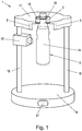
- a device 1 according to the invention for determining the concentration of a predetermined gas in a sample 2 is shown.
- the device 1 comprises a light source 3 with a tunable diode laser 4 (see. Fig. 2 ).
- the diode laser 4 includes a DFB (distributed feedback) laser diode (not shown) for radiating substantially monochromatic light into the sample 2.
- the diode laser 4 is arranged to emit laser light having a wavelength between 1810 and 1850 nm, that is, between 1810 and 1850 nm tunable.
- the device 1 also comprises a measuring unit 5 with a light sensor 6 for measuring the intensity of the light emerging from the sample 2. Furthermore, the device 1 comprises a control unit 7 for controlling the pumping current of the laser diode of the diode laser 4. Finally, the device also comprises an evaluation unit 8.
- the control unit 7 is set up to vary the pumping current of the laser diode of the diode laser 4 over time, in particular periodically to modulate. Specifically, it is set up as a pumping current of the laser diode of the diode laser 4 during a first time interval 9 (cf. Fig. 4 ) to specify a substantially constant and non-zero base stream 10. In the present example, this base current 10 corresponds to the laser threshold value of the diode laser 4.
- the control unit 7 is also set to predetermine a current ramp 12, which rises continuously from the base current 10, as pumping current of the laser diode of the diode laser 4 during a second time interval 11. Furthermore, control unit is set up to predetermine a pumping current I decreasing in three stages relative to the base current 10 during a third time interval 29.
- the evaluation unit 8 is connected to the light sensor 6 and to the control unit 7. It is also set up to calculate the concentration of the gas as a function of the pumping current predetermined by the control unit 7 and the intensity of the light transmitted through the sample 2 measured by the light sensor 6.
- Sample 2 in Fig. 1 is a liquid-empty headspace of a sample container 13 in the form of a closed PET bottle containing a beverage 14 (mainly water).
- the relative humidity in the headspace is essentially 100%, ie there is water vapor here.
- the sample container 13 is substantially transparent to light in the infrared region. It is in a substantially U-shaped insertion bracket 15th taken and is supported by the insertion bracket 15 on a closure collar 16 of the sample container 13.
- An upper part 17 of the device 1 is connected to a base 19 by means of two support elements 18 in the form of rods. On one of the support elements 18, a temperature measuring device 20 in the form of an infrared temperature measuring device is arranged below the upper part 17.
- the temperature measuring device 20 is set up to measure the temperature on an outer wall of the sample container 13. In operation of the device 1, in addition to the absorption spectrum with the temperature measuring device 20, the temperature on the outer wall of the sample container 13 is measured and taken into account in the calculation of the concentration of the gas.
- a display 21 for displaying the determined concentration or the determined partial pressure is provided on the base 19, a display 21 for displaying the determined concentration or the determined partial pressure is provided.
- Fig. 2 is the optical system of the device 1 together with a simplified beam path 22 and the only schematically drawn functional units 3, 5, 7, 8 of the device 1 and their interconnections shown.
- the optical system of the device 1 comprises two diffusion elements 23, 24.
- the diffusion elements 23, 24 are each arranged to transmit and scatter the light emitted by the laser diode of the diode laser 4 (emitted).
- a first diffusion element 23 diffuses the light before entering the sample 2.
- a second diffusion element 24 scatters the light after exiting the sample 2.
- a converging lens 25, 26 is provided in the light source 3 and the measuring unit 5.
- a first converging lens 25 in the light source 3 is arranged to focus on the light emitted by the laser diode of the diode laser 4 before scattering on the first diffusion element 23.
- a second converging lens 26 in the measuring unit 5 is arranged to focus the light emerging from the sample 2 before scattering on the second diffusion element 24.
- Fig. 3a shows a measured by an exemplary measurement and test arrangement geometric intensity distribution of the diode laser 4 emitted laser light in an image plane normal to the optical axis 27 for an optical system, which except for the diffusion elements 23, 24 and converging lenses 25, 26 the in Fig. 2 represented system corresponds.
- Fig. 3b shows by comparison a corresponding geometric intensity distribution using the in Fig. 2 illustrated optical system, ie with diffusion elements 23, 24 and converging lenses 25, 26. It can be clearly seen that in the distribution in Fig. 3b the intensity peaks (local maxima) of the distribution in Fig. 3a were eliminated. The intensity distribution corresponds approximately to an even distribution in the image plane. The uniform intensity distribution thus obtained remains substantially the same with changes in the pumping current and is independent of the type and size of the laser.
- the converging lenses 25, 26 may also be configured to at least partially compensate for refractions on the sample container.
- the concentration of a predetermined gas, eg nitrogen, in the sample 2 can be determined by the present method.
- the wavelength (actually the central wavelength of the emission spectrum) of the substantially monochromatic light radiated by the diode laser 4 into the sample 2 is varied and modulated in time by changing the pumping current I of the laser diode of the diode laser 4 (cf. Fig. 4 ).
- the intensity of the light emerging from the sample 2 is measured with the measuring unit 5 and the concentration of the gas in the sample is calculated as a function of the time profile of the pumping current I and the time course of the measured intensity in the evaluation unit 8.
- the line broadening in the absorption spectrum determined from the intensity distribution as a function of the pumping current is determined and closed by this line broadening to the partial pressure of water vapor in the sample.
- the relationship between this partial pressure and the partial pressure of the desired gas (eg nitrogen) can be determined in advance by calibration and then used for the measurement.
- the calibration can be carried out, for example, using one or more reference samples with a known nitrogen concentration.
- Fig. 4 is the time course of a period 28 of the pumping current I of the laser diode of the diode laser 4 of the device 1 according to Fig. 1 shown schematically.
- the duration of a period 28 in this example is 100 ms.
- the period 28 is repeated in a loop, resulting in a pulse frequency of the pump current corresponding to the inverse period, ie, for example, a pulse frequency of 10 Hz.
- the period 28 is in a first temporal portion 9, a second temporal section 11 and a third temporal section 29 divided.
- the duration of the individual time segments is not shown proportionally.
- the pump current I in the first time interval 9 corresponds to a substantially constant and non-zero background current 10.
- the base current 10 corresponds approximately to the laser threshold value of the laser diode of the diode laser 4.
- the laser diode is constantly driven in laser mode and at the same time as possible low temperature development achieved in this operating mode.
- the base current is 5 mA.
- the duration of the first temporal section 9 in this example is about 84.9 ms.
- the pumping current I is changed or raised by the control unit 7 in accordance with a current ramp 12 which rises continuously from the basic current 10 up to a limiting current 30.
- the duration of the second time segment 11 in this example is exactly 15 ms.
- the limit current is about 100 mA.
- the third temporal section 29 follows immediately, in which the pumping current I is changed or shut down in three stages 31 toward the basic flow 10.
- the duration of each stage is maximum 35 ⁇ s (Microseconds), so that a total of a duration of the third temporal portion 29 of at most about 100 microseconds (that is about 0.1 ms) results.
Landscapes
- Physics & Mathematics (AREA)
- General Physics & Mathematics (AREA)
- Health & Medical Sciences (AREA)
- Life Sciences & Earth Sciences (AREA)
- Chemical & Material Sciences (AREA)
- Spectroscopy & Molecular Physics (AREA)
- Analytical Chemistry (AREA)
- Biochemistry (AREA)
- General Health & Medical Sciences (AREA)
- Pathology (AREA)
- Immunology (AREA)
- Optics & Photonics (AREA)
- Engineering & Computer Science (AREA)
- Food Science & Technology (AREA)
- Medicinal Chemistry (AREA)
- Investigating Or Analysing Materials By Optical Means (AREA)
Applications Claiming Priority (1)
| Application Number | Priority Date | Filing Date | Title |
|---|---|---|---|
| ATA50138/2017A AT519690B1 (de) | 2017-02-21 | 2017-02-21 | Verfahren und Vorrichtung zur Ermittlung der Konzentration eines vorbestimmten Gases |
Publications (3)
| Publication Number | Publication Date |
|---|---|
| EP3364170A1 true EP3364170A1 (fr) | 2018-08-22 |
| EP3364170B1 EP3364170B1 (fr) | 2023-11-22 |
| EP3364170B8 EP3364170B8 (fr) | 2023-12-27 |
Family
ID=61256658
Family Applications (1)
| Application Number | Title | Priority Date | Filing Date |
|---|---|---|---|
| EP18157812.1A Active EP3364170B8 (fr) | 2017-02-21 | 2018-02-21 | Mesure de la concentration de gaz dans un récipient |
Country Status (3)
| Country | Link |
|---|---|
| EP (1) | EP3364170B8 (fr) |
| AT (1) | AT519690B1 (fr) |
| ES (1) | ES2963842T3 (fr) |
Cited By (3)
| Publication number | Priority date | Publication date | Assignee | Title |
|---|---|---|---|---|
| AT521681A4 (de) * | 2018-11-09 | 2020-04-15 | Acm Automatisierung Computertechnik Mess Und Regeltechnik Gmbh | Labor-Gasmessgerät |
| AT521839A1 (de) * | 2018-11-09 | 2020-05-15 | Acm Automatisierung Computertechnik Mess Und Regeltechnik Gmbh | Labor-Gasmessgerät |
| CN117470450A (zh) * | 2023-12-27 | 2024-01-30 | 广州煌之牌包装机械有限公司 | 一种西林瓶多头式轧盖检漏方法及系统 |
Citations (4)
| Publication number | Priority date | Publication date | Assignee | Title |
|---|---|---|---|---|
| DE19840345A1 (de) * | 1998-09-04 | 2000-03-09 | Draeger Medizintech Gmbh | Verfahren und Vorrichtung zum quantitativen Aufspüren eines vorgegebenen Gases |
| US20080092648A1 (en) * | 2006-10-18 | 2008-04-24 | Xin Zhou | Detection of moisture in refrigerants |
| EP2610608A1 (fr) * | 2011-12-27 | 2013-07-03 | HORIBA, Ltd. | Appareil de mesure de gaz et procédé de réglage de la largeur de modulation de la longueur d'onde dans un appareil de mesure de gaz |
| DE102013201459A1 (de) * | 2013-01-30 | 2014-07-31 | Siemens Aktiengesellschaft | Verfahren zur Messung der Konzentration einer Gaskomponente in einem Messgas |
Family Cites Families (5)
| Publication number | Priority date | Publication date | Assignee | Title |
|---|---|---|---|---|
| US4730112A (en) * | 1986-03-07 | 1988-03-08 | Hibshman Corporation | Oxygen measurement using visible radiation |
| US5331409A (en) * | 1992-06-12 | 1994-07-19 | George Thurtell | Tunable diode laser gas analyzer |
| DE102011079342B3 (de) * | 2011-07-18 | 2012-12-06 | Siemens Aktiengesellschaft | Verfahren zur Ansteuerung einer Laserdiode in einem Spektrometer |
| DE102013213458B4 (de) * | 2013-07-09 | 2015-07-09 | Siemens Aktiengesellschaft | Verfahren zur Messung der Konzentration einer Gaskomponente in einem Messgas |
| SE538814C2 (sv) * | 2015-04-02 | 2016-12-13 | Gasporox Ab | System and method for determining the integrity of containers by optical measurement |
-
2017
- 2017-02-21 AT ATA50138/2017A patent/AT519690B1/de active
-
2018
- 2018-02-21 EP EP18157812.1A patent/EP3364170B8/fr active Active
- 2018-02-21 ES ES18157812T patent/ES2963842T3/es active Active
Patent Citations (4)
| Publication number | Priority date | Publication date | Assignee | Title |
|---|---|---|---|---|
| DE19840345A1 (de) * | 1998-09-04 | 2000-03-09 | Draeger Medizintech Gmbh | Verfahren und Vorrichtung zum quantitativen Aufspüren eines vorgegebenen Gases |
| US20080092648A1 (en) * | 2006-10-18 | 2008-04-24 | Xin Zhou | Detection of moisture in refrigerants |
| EP2610608A1 (fr) * | 2011-12-27 | 2013-07-03 | HORIBA, Ltd. | Appareil de mesure de gaz et procédé de réglage de la largeur de modulation de la longueur d'onde dans un appareil de mesure de gaz |
| DE102013201459A1 (de) * | 2013-01-30 | 2014-07-31 | Siemens Aktiengesellschaft | Verfahren zur Messung der Konzentration einer Gaskomponente in einem Messgas |
Non-Patent Citations (1)
| Title |
|---|
| MCMANUS J B ET AL: "Compact Quantum Cascade Laser Instrument for Rapid, High Sensitivity Measurements of Trace Gases in Air", SENSORS, 2007 IEEE, IEEE, PI, 28 October 2007 (2007-10-28), pages 1341 - 1344, XP031221319, ISBN: 978-1-4244-1261-7 * |
Cited By (6)
| Publication number | Priority date | Publication date | Assignee | Title |
|---|---|---|---|---|
| AT521681A4 (de) * | 2018-11-09 | 2020-04-15 | Acm Automatisierung Computertechnik Mess Und Regeltechnik Gmbh | Labor-Gasmessgerät |
| AT521681B1 (de) * | 2018-11-09 | 2020-04-15 | Acm Automatisierung Computertechnik Mess Und Regeltechnik Gmbh | Labor-Gasmessgerät |
| EP3650840A1 (fr) | 2018-11-09 | 2020-05-13 | ACM-Automatisierung, Computertechnik, Meß- und Regeltechnik GmbH | Appareil de mesure des gaz de laboratoire |
| AT521839A1 (de) * | 2018-11-09 | 2020-05-15 | Acm Automatisierung Computertechnik Mess Und Regeltechnik Gmbh | Labor-Gasmessgerät |
| CN117470450A (zh) * | 2023-12-27 | 2024-01-30 | 广州煌之牌包装机械有限公司 | 一种西林瓶多头式轧盖检漏方法及系统 |
| CN117470450B (zh) * | 2023-12-27 | 2024-03-01 | 广州煌之牌包装机械有限公司 | 一种西林瓶多头式轧盖检漏方法及系统 |
Also Published As
| Publication number | Publication date |
|---|---|
| AT519690B1 (de) | 2018-12-15 |
| EP3364170B1 (fr) | 2023-11-22 |
| ES2963842T3 (es) | 2024-04-02 |
| EP3364170B8 (fr) | 2023-12-27 |
| AT519690A1 (de) | 2018-09-15 |
Similar Documents
| Publication | Publication Date | Title |
|---|---|---|
| EP2433108B1 (fr) | Procédé et dispositif pour mesurer par voie optique la pression d'un gaz dans un contenant fermé | |
| DE102013202289B4 (de) | Verfahren und Anordnung zur Ansteuerung einer wellenlängendurchstimmbaren Laserdiode in einem Spektrometer | |
| EP3658896A1 (fr) | Procédé d'examen spectroscopique et/ou spectrométrique d'un échantillon et dispositif interférométrique | |
| EP2520924A1 (fr) | Procédé et agencement de mesure pour l'amélioration de la dissolution de signal dans la spectroscopie d'absorption de gaz | |
| AT519690B1 (de) | Verfahren und Vorrichtung zur Ermittlung der Konzentration eines vorbestimmten Gases | |
| DE102009028994B3 (de) | Vorrichtung und Verfahren zum spektroskopischen Nachweis von Molekülen | |
| DE112009001711T5 (de) | Vorrichtung zur Messung von Infrarotabsorption und Verfahren zur Messung von Infrarotabsorption | |
| DE4122572A1 (de) | Verfahren zum betrieb einer laserdiode | |
| DE102016108267B4 (de) | Vorrichtung und Verfahren zum Ermitteln einer Konzentration von wenigstens einer Gaskomponente eines Gasgemischs | |
| EP2132551B1 (fr) | Détecteur photoacoustique comportant deux trajectoires de faisceau pour la lumière d'excitation | |
| WO2013135611A2 (fr) | Dispositif et procédé de mesure d'un gaz cible | |
| EP3104163B1 (fr) | Analyseur de gaz de processus et procédé d'analyse d'un gaz de processus | |
| DE102014104043B4 (de) | Multireflexionszellenanordnung | |
| AT500543B1 (de) | Verfahren zur raschen spektroskopischen konzentrations-, temperatur- und druckmessung von gasförmigem wasser | |
| EP4133258B1 (fr) | Procédé et dispositif de détermination d'indices de réfraction dépendant de la fréquence | |
| EP3816609B1 (fr) | Dispositif et procédé de détection à distance d'un gaz cible | |
| WO2004008112A1 (fr) | Spectrometre d'absorption a haute resolution et procede de mesure correspondant | |
| EP3771900B1 (fr) | Procédé de détermination d'une concentration en gaz et appareil de mesure | |
| WO2004008113A1 (fr) | Spectrometre d'absorption et procede de mesure correspondant | |
| DE102022100233A1 (de) | Messung gelösten sauerstoffs mit hilfe der durch optische strahlung induzierten lumineszenz | |
| DE102016207995A1 (de) | Optischer Resonator für eine Sensorvorrichtung zum Detektieren eines Fluids, Sensorvorrichtung zum Detektieren eines Fluids und Verfahren zum Detektieren eines Fluids | |
| AT520428B1 (de) | Verfahren und Vorrichtung zur Messung eines in einem Rohgas | |
| DE102015118208B4 (de) | Analysevorrichtung zum Analysieren einer Gasprobe sowie Verfahren zum Analysieren einer Gasprobe | |
| EP3163292B1 (fr) | Méthode de calibration et d'utilisation d'un spectromètre laser | |
| DE102019125170B4 (de) | Detektorsystem für geladene Aerosole, entsprechendes Verfahren und Verwendung |
Legal Events
| Date | Code | Title | Description |
|---|---|---|---|
| PUAI | Public reference made under article 153(3) epc to a published international application that has entered the european phase |
Free format text: ORIGINAL CODE: 0009012 |
|
| STAA | Information on the status of an ep patent application or granted ep patent |
Free format text: STATUS: THE APPLICATION HAS BEEN PUBLISHED |
|
| AK | Designated contracting states |
Kind code of ref document: A1 Designated state(s): AL AT BE BG CH CY CZ DE DK EE ES FI FR GB GR HR HU IE IS IT LI LT LU LV MC MK MT NL NO PL PT RO RS SE SI SK SM TR |
|
| AX | Request for extension of the european patent |
Extension state: BA ME |
|
| STAA | Information on the status of an ep patent application or granted ep patent |
Free format text: STATUS: REQUEST FOR EXAMINATION WAS MADE |
|
| 17P | Request for examination filed |
Effective date: 20190219 |
|
| RBV | Designated contracting states (corrected) |
Designated state(s): AL AT BE BG CH CY CZ DE DK EE ES FI FR GB GR HR HU IE IS IT LI LT LU LV MC MK MT NL NO PL PT RO RS SE SI SK SM TR |
|
| STAA | Information on the status of an ep patent application or granted ep patent |
Free format text: STATUS: EXAMINATION IS IN PROGRESS |
|
| 17Q | First examination report despatched |
Effective date: 20200408 |
|
| GRAP | Despatch of communication of intention to grant a patent |
Free format text: ORIGINAL CODE: EPIDOSNIGR1 |
|
| STAA | Information on the status of an ep patent application or granted ep patent |
Free format text: STATUS: GRANT OF PATENT IS INTENDED |
|
| INTG | Intention to grant announced |
Effective date: 20230523 |
|
| GRAS | Grant fee paid |
Free format text: ORIGINAL CODE: EPIDOSNIGR3 |
|
| GRAA | (expected) grant |
Free format text: ORIGINAL CODE: 0009210 |
|
| STAA | Information on the status of an ep patent application or granted ep patent |
Free format text: STATUS: THE PATENT HAS BEEN GRANTED |
|
| GRAT | Correction requested after decision to grant or after decision to maintain patent in amended form |
Free format text: ORIGINAL CODE: EPIDOSNCDEC |
|
| REG | Reference to a national code |
Ref country code: DE Ref legal event code: R081 Ref document number: 502018013649 Country of ref document: DE Owner name: ACM-AUTOMATISIERUNG, COMPUTERTECHNIK, MESS- UN, AT Free format text: FORMER OWNER: ACM GMBH, WIEN, AT |
|
| AK | Designated contracting states |
Kind code of ref document: B1 Designated state(s): AL AT BE BG CH CY CZ DE DK EE ES FI FR GB GR HR HU IE IS IT LI LT LU LV MC MK MT NL NO PL PT RO RS SE SI SK SM TR |
|
| REG | Reference to a national code |
Ref country code: GB Ref legal event code: FG4D Free format text: NOT ENGLISH |
|
| REG | Reference to a national code |
Ref country code: CH Ref legal event code: PK Free format text: BERICHTIGUNG B8 Ref country code: CH Ref legal event code: EP |
|
| RAP4 | Party data changed (patent owner data changed or rights of a patent transferred) |
Owner name: ACM-AUTOMATISIERUNG, COMPUTERTECHNIK, MESS- UND REGELTECHNIK GMBH |
|
| REG | Reference to a national code |
Ref country code: DE Ref legal event code: R096 Ref document number: 502018013649 Country of ref document: DE |
|
| REG | Reference to a national code |
Ref country code: IE Ref legal event code: FG4D Free format text: LANGUAGE OF EP DOCUMENT: GERMAN |
|
| REG | Reference to a national code |
Ref country code: LT Ref legal event code: MG9D |
|
| REG | Reference to a national code |
Ref country code: NL Ref legal event code: MP Effective date: 20231122 |
|
| REG | Reference to a national code |
Ref country code: ES Ref legal event code: FG2A Ref document number: 2963842 Country of ref document: ES Kind code of ref document: T3 Effective date: 20240402 |
|
| PG25 | Lapsed in a contracting state [announced via postgrant information from national office to epo] |
Ref country code: GR Free format text: LAPSE BECAUSE OF FAILURE TO SUBMIT A TRANSLATION OF THE DESCRIPTION OR TO PAY THE FEE WITHIN THE PRESCRIBED TIME-LIMIT Effective date: 20240223 |
|
| PG25 | Lapsed in a contracting state [announced via postgrant information from national office to epo] |
Ref country code: IS Free format text: LAPSE BECAUSE OF FAILURE TO SUBMIT A TRANSLATION OF THE DESCRIPTION OR TO PAY THE FEE WITHIN THE PRESCRIBED TIME-LIMIT Effective date: 20240322 |
|
| PG25 | Lapsed in a contracting state [announced via postgrant information from national office to epo] |
Ref country code: LT Free format text: LAPSE BECAUSE OF FAILURE TO SUBMIT A TRANSLATION OF THE DESCRIPTION OR TO PAY THE FEE WITHIN THE PRESCRIBED TIME-LIMIT Effective date: 20231122 |
|
| PG25 | Lapsed in a contracting state [announced via postgrant information from national office to epo] |
Ref country code: NL Free format text: LAPSE BECAUSE OF FAILURE TO SUBMIT A TRANSLATION OF THE DESCRIPTION OR TO PAY THE FEE WITHIN THE PRESCRIBED TIME-LIMIT Effective date: 20231122 |
|
| PG25 | Lapsed in a contracting state [announced via postgrant information from national office to epo] |
Ref country code: NL Free format text: LAPSE BECAUSE OF FAILURE TO SUBMIT A TRANSLATION OF THE DESCRIPTION OR TO PAY THE FEE WITHIN THE PRESCRIBED TIME-LIMIT Effective date: 20231122 Ref country code: LT Free format text: LAPSE BECAUSE OF FAILURE TO SUBMIT A TRANSLATION OF THE DESCRIPTION OR TO PAY THE FEE WITHIN THE PRESCRIBED TIME-LIMIT Effective date: 20231122 Ref country code: IS Free format text: LAPSE BECAUSE OF FAILURE TO SUBMIT A TRANSLATION OF THE DESCRIPTION OR TO PAY THE FEE WITHIN THE PRESCRIBED TIME-LIMIT Effective date: 20240322 Ref country code: GR Free format text: LAPSE BECAUSE OF FAILURE TO SUBMIT A TRANSLATION OF THE DESCRIPTION OR TO PAY THE FEE WITHIN THE PRESCRIBED TIME-LIMIT Effective date: 20240223 Ref country code: BG Free format text: LAPSE BECAUSE OF FAILURE TO SUBMIT A TRANSLATION OF THE DESCRIPTION OR TO PAY THE FEE WITHIN THE PRESCRIBED TIME-LIMIT Effective date: 20240222 Ref country code: PT Free format text: LAPSE BECAUSE OF FAILURE TO SUBMIT A TRANSLATION OF THE DESCRIPTION OR TO PAY THE FEE WITHIN THE PRESCRIBED TIME-LIMIT Effective date: 20240322 |
|
| PG25 | Lapsed in a contracting state [announced via postgrant information from national office to epo] |
Ref country code: SE Free format text: LAPSE BECAUSE OF FAILURE TO SUBMIT A TRANSLATION OF THE DESCRIPTION OR TO PAY THE FEE WITHIN THE PRESCRIBED TIME-LIMIT Effective date: 20231122 Ref country code: RS Free format text: LAPSE BECAUSE OF FAILURE TO SUBMIT A TRANSLATION OF THE DESCRIPTION OR TO PAY THE FEE WITHIN THE PRESCRIBED TIME-LIMIT Effective date: 20231122 Ref country code: PL Free format text: LAPSE BECAUSE OF FAILURE TO SUBMIT A TRANSLATION OF THE DESCRIPTION OR TO PAY THE FEE WITHIN THE PRESCRIBED TIME-LIMIT Effective date: 20231122 Ref country code: NO Free format text: LAPSE BECAUSE OF FAILURE TO SUBMIT A TRANSLATION OF THE DESCRIPTION OR TO PAY THE FEE WITHIN THE PRESCRIBED TIME-LIMIT Effective date: 20240222 Ref country code: LV Free format text: LAPSE BECAUSE OF FAILURE TO SUBMIT A TRANSLATION OF THE DESCRIPTION OR TO PAY THE FEE WITHIN THE PRESCRIBED TIME-LIMIT Effective date: 20231122 Ref country code: HR Free format text: LAPSE BECAUSE OF FAILURE TO SUBMIT A TRANSLATION OF THE DESCRIPTION OR TO PAY THE FEE WITHIN THE PRESCRIBED TIME-LIMIT Effective date: 20231122 |
|
| PG25 | Lapsed in a contracting state [announced via postgrant information from national office to epo] |
Ref country code: DK Free format text: LAPSE BECAUSE OF FAILURE TO SUBMIT A TRANSLATION OF THE DESCRIPTION OR TO PAY THE FEE WITHIN THE PRESCRIBED TIME-LIMIT Effective date: 20231122 |
|
| PG25 | Lapsed in a contracting state [announced via postgrant information from national office to epo] |
Ref country code: CZ Free format text: LAPSE BECAUSE OF FAILURE TO SUBMIT A TRANSLATION OF THE DESCRIPTION OR TO PAY THE FEE WITHIN THE PRESCRIBED TIME-LIMIT Effective date: 20231122 |
|
| PG25 | Lapsed in a contracting state [announced via postgrant information from national office to epo] |
Ref country code: SK Free format text: LAPSE BECAUSE OF FAILURE TO SUBMIT A TRANSLATION OF THE DESCRIPTION OR TO PAY THE FEE WITHIN THE PRESCRIBED TIME-LIMIT Effective date: 20231122 |
|
| PG25 | Lapsed in a contracting state [announced via postgrant information from national office to epo] |
Ref country code: SM Free format text: LAPSE BECAUSE OF FAILURE TO SUBMIT A TRANSLATION OF THE DESCRIPTION OR TO PAY THE FEE WITHIN THE PRESCRIBED TIME-LIMIT Effective date: 20231122 Ref country code: SK Free format text: LAPSE BECAUSE OF FAILURE TO SUBMIT A TRANSLATION OF THE DESCRIPTION OR TO PAY THE FEE WITHIN THE PRESCRIBED TIME-LIMIT Effective date: 20231122 Ref country code: RO Free format text: LAPSE BECAUSE OF FAILURE TO SUBMIT A TRANSLATION OF THE DESCRIPTION OR TO PAY THE FEE WITHIN THE PRESCRIBED TIME-LIMIT Effective date: 20231122 Ref country code: EE Free format text: LAPSE BECAUSE OF FAILURE TO SUBMIT A TRANSLATION OF THE DESCRIPTION OR TO PAY THE FEE WITHIN THE PRESCRIBED TIME-LIMIT Effective date: 20231122 Ref country code: DK Free format text: LAPSE BECAUSE OF FAILURE TO SUBMIT A TRANSLATION OF THE DESCRIPTION OR TO PAY THE FEE WITHIN THE PRESCRIBED TIME-LIMIT Effective date: 20231122 Ref country code: CZ Free format text: LAPSE BECAUSE OF FAILURE TO SUBMIT A TRANSLATION OF THE DESCRIPTION OR TO PAY THE FEE WITHIN THE PRESCRIBED TIME-LIMIT Effective date: 20231122 |
|
| REG | Reference to a national code |
Ref country code: DE Ref legal event code: R097 Ref document number: 502018013649 Country of ref document: DE |
|
| PLBE | No opposition filed within time limit |
Free format text: ORIGINAL CODE: 0009261 |
|
| STAA | Information on the status of an ep patent application or granted ep patent |
Free format text: STATUS: NO OPPOSITION FILED WITHIN TIME LIMIT |
|
| PG25 | Lapsed in a contracting state [announced via postgrant information from national office to epo] |
Ref country code: MC Free format text: LAPSE BECAUSE OF FAILURE TO SUBMIT A TRANSLATION OF THE DESCRIPTION OR TO PAY THE FEE WITHIN THE PRESCRIBED TIME-LIMIT Effective date: 20231122 |
|
| PG25 | Lapsed in a contracting state [announced via postgrant information from national office to epo] |
Ref country code: LU Free format text: LAPSE BECAUSE OF NON-PAYMENT OF DUE FEES Effective date: 20240221 |
|
| PG25 | Lapsed in a contracting state [announced via postgrant information from national office to epo] |
Ref country code: SI Free format text: LAPSE BECAUSE OF FAILURE TO SUBMIT A TRANSLATION OF THE DESCRIPTION OR TO PAY THE FEE WITHIN THE PRESCRIBED TIME-LIMIT Effective date: 20231122 |
|
| 26N | No opposition filed |
Effective date: 20240823 |
|
| PG25 | Lapsed in a contracting state [announced via postgrant information from national office to epo] |
Ref country code: SI Free format text: LAPSE BECAUSE OF FAILURE TO SUBMIT A TRANSLATION OF THE DESCRIPTION OR TO PAY THE FEE WITHIN THE PRESCRIBED TIME-LIMIT Effective date: 20231122 Ref country code: LU Free format text: LAPSE BECAUSE OF NON-PAYMENT OF DUE FEES Effective date: 20240221 |
|
| REG | Reference to a national code |
Ref country code: BE Ref legal event code: MM Effective date: 20240229 |
|
| PG25 | Lapsed in a contracting state [announced via postgrant information from national office to epo] |
Ref country code: BE Free format text: LAPSE BECAUSE OF NON-PAYMENT OF DUE FEES Effective date: 20240229 |
|
| PG25 | Lapsed in a contracting state [announced via postgrant information from national office to epo] |
Ref country code: IE Free format text: LAPSE BECAUSE OF NON-PAYMENT OF DUE FEES Effective date: 20240221 |
|
| PG25 | Lapsed in a contracting state [announced via postgrant information from national office to epo] |
Ref country code: IE Free format text: LAPSE BECAUSE OF NON-PAYMENT OF DUE FEES Effective date: 20240221 Ref country code: BE Free format text: LAPSE BECAUSE OF NON-PAYMENT OF DUE FEES Effective date: 20240229 |
|
| PG25 | Lapsed in a contracting state [announced via postgrant information from national office to epo] |
Ref country code: CY Free format text: LAPSE BECAUSE OF FAILURE TO SUBMIT A TRANSLATION OF THE DESCRIPTION OR TO PAY THE FEE WITHIN THE PRESCRIBED TIME-LIMIT; INVALID AB INITIO Effective date: 20180221 |
|
| PG25 | Lapsed in a contracting state [announced via postgrant information from national office to epo] |
Ref country code: HU Free format text: LAPSE BECAUSE OF FAILURE TO SUBMIT A TRANSLATION OF THE DESCRIPTION OR TO PAY THE FEE WITHIN THE PRESCRIBED TIME-LIMIT; INVALID AB INITIO Effective date: 20180221 |
|
| PG25 | Lapsed in a contracting state [announced via postgrant information from national office to epo] |
Ref country code: FI Free format text: LAPSE BECAUSE OF FAILURE TO SUBMIT A TRANSLATION OF THE DESCRIPTION OR TO PAY THE FEE WITHIN THE PRESCRIBED TIME-LIMIT Effective date: 20231122 |
|
| PG25 | Lapsed in a contracting state [announced via postgrant information from national office to epo] |
Ref country code: TR Free format text: LAPSE BECAUSE OF FAILURE TO SUBMIT A TRANSLATION OF THE DESCRIPTION OR TO PAY THE FEE WITHIN THE PRESCRIBED TIME-LIMIT Effective date: 20231122 |
|
| PGFP | Annual fee paid to national office [announced via postgrant information from national office to epo] |
Ref country code: FR Payment date: 20251217 Year of fee payment: 9 |
|
| REG | Reference to a national code |
Ref country code: CH Ref legal event code: U11 Free format text: ST27 STATUS EVENT CODE: U-0-0-U10-U11 (AS PROVIDED BY THE NATIONAL OFFICE) Effective date: 20260301 |
|
| PGFP | Annual fee paid to national office [announced via postgrant information from national office to epo] |
Ref country code: GB Payment date: 20260219 Year of fee payment: 9 |
|
| PGFP | Annual fee paid to national office [announced via postgrant information from national office to epo] |
Ref country code: ES Payment date: 20260302 Year of fee payment: 9 |
|
| PGFP | Annual fee paid to national office [announced via postgrant information from national office to epo] |
Ref country code: DE Payment date: 20260226 Year of fee payment: 9 |
|
| PGFP | Annual fee paid to national office [announced via postgrant information from national office to epo] |
Ref country code: AT Payment date: 20260210 Year of fee payment: 9 |
|
| PGFP | Annual fee paid to national office [announced via postgrant information from national office to epo] |
Ref country code: IT Payment date: 20260205 Year of fee payment: 9 |
|
| PGFP | Annual fee paid to national office [announced via postgrant information from national office to epo] |
Ref country code: CH Payment date: 20260301 Year of fee payment: 9 |