EP3366185A1 - Geschirrspülmaschine - Google Patents
Geschirrspülmaschine Download PDFInfo
- Publication number
- EP3366185A1 EP3366185A1 EP17158124.2A EP17158124A EP3366185A1 EP 3366185 A1 EP3366185 A1 EP 3366185A1 EP 17158124 A EP17158124 A EP 17158124A EP 3366185 A1 EP3366185 A1 EP 3366185A1
- Authority
- EP
- European Patent Office
- Prior art keywords
- rinsing
- catchment
- catchment sink
- liquid
- sink
- Prior art date
- Legal status (The legal status is an assumption and is not a legal conclusion. Google has not performed a legal analysis and makes no representation as to the accuracy of the status listed.)
- Granted
Links
Images



Classifications
-
- A—HUMAN NECESSITIES
- A47—FURNITURE; DOMESTIC ARTICLES OR APPLIANCES; COFFEE MILLS; SPICE MILLS; SUCTION CLEANERS IN GENERAL
- A47L—DOMESTIC WASHING OR CLEANING; SUCTION CLEANERS IN GENERAL
- A47L15/00—Washing or rinsing machines for crockery or tableware
- A47L15/0018—Controlling processes, i.e. processes to control the operation of the machine characterised by the purpose or target of the control
- A47L15/0047—Energy or water consumption, e.g. by saving energy or water
-
- A—HUMAN NECESSITIES
- A47—FURNITURE; DOMESTIC ARTICLES OR APPLIANCES; COFFEE MILLS; SPICE MILLS; SUCTION CLEANERS IN GENERAL
- A47L—DOMESTIC WASHING OR CLEANING; SUCTION CLEANERS IN GENERAL
- A47L15/00—Washing or rinsing machines for crockery or tableware
- A47L15/0002—Washing processes, i.e. machine working principles characterised by phases or operational steps
- A47L15/0005—Rinsing phases, e.g. pre-rinsing, intermediate rinsing, final rinsing
-
- A—HUMAN NECESSITIES
- A47—FURNITURE; DOMESTIC ARTICLES OR APPLIANCES; COFFEE MILLS; SPICE MILLS; SUCTION CLEANERS IN GENERAL
- A47L—DOMESTIC WASHING OR CLEANING; SUCTION CLEANERS IN GENERAL
- A47L15/00—Washing or rinsing machines for crockery or tableware
- A47L15/0076—Washing or rinsing machines for crockery or tableware of non-domestic use type, e.g. commercial dishwashers for bars, hotels, restaurants, canteens or hospitals
- A47L15/0078—Washing or rinsing machines for crockery or tableware of non-domestic use type, e.g. commercial dishwashers for bars, hotels, restaurants, canteens or hospitals with a plurality of fluid recirculation arrangements, e.g. with separated washing liquid and rinsing liquid recirculation circuits
-
- A—HUMAN NECESSITIES
- A47—FURNITURE; DOMESTIC ARTICLES OR APPLIANCES; COFFEE MILLS; SPICE MILLS; SUCTION CLEANERS IN GENERAL
- A47L—DOMESTIC WASHING OR CLEANING; SUCTION CLEANERS IN GENERAL
- A47L15/00—Washing or rinsing machines for crockery or tableware
- A47L15/24—Washing or rinsing machines for crockery or tableware with movement of the crockery baskets by conveyors
- A47L15/241—Washing or rinsing machines for crockery or tableware with movement of the crockery baskets by conveyors the dishes moving in a horizontal plane
-
- A—HUMAN NECESSITIES
- A47—FURNITURE; DOMESTIC ARTICLES OR APPLIANCES; COFFEE MILLS; SPICE MILLS; SUCTION CLEANERS IN GENERAL
- A47L—DOMESTIC WASHING OR CLEANING; SUCTION CLEANERS IN GENERAL
- A47L2401/00—Automatic detection in controlling methods of washing or rinsing machines for crockery or tableware, e.g. information provided by sensors entered into controlling devices
- A47L2401/09—Water level
Definitions
- the present invention relates to a dishwashing machine.
- the present invention relates to a rack-type dishwashing machine, to which the following description will make explicit reference without however losing in generality.
- a rack-type dishwashing machine also called tunnel dishwashing machine, basically comprises: a boxlike outer casing provided with a rectilinear, pass-through tunnel extending substantially horizontally within the casing; and a linear conveyor adapted to advance a succession of dishwasher racks along the pass-through tunnel.
- a washing station and a rinsing station are moreover arranged one downstream the other inside the pass-through tunnel, so as to be crossed in succession by each dishwasher rack travelling inside the pass-through tunnel.
- a number of high-pressure jets of hot water at nearly 60°C mixed with detergent/s are directed towards the dishwasher rack momentarily located at washing station, so as to remove the filth from the dishware in said dishwasher rack.
- a number of high-pressure jets of hot water at nearly 80°C mixed with rinse agent/s are directed towards the dishwasher rack momentarily located at rinsing station, so as to remove any residual of detergent/s from the dishware in said dishwasher rack and sanitize the same dishware.
- the rack-type dishwashing machine generally comprises: a large washing-water catchment sink which is arranged on the bottom of the tunnel for collecting and accumulating the mixture of water and detergent/s trickling down from the dishware in the dishwasher rack; a number of washing nozzles which are arranged above and beneath the moving path of the dishwasher racks, and are oriented so as to direct the corresponding water jets towards the dishwasher rack momentarily located at rinsing station; a water-circulating pump that sucks the mixture of water and detergent/s from the aforesaid catchment sink and feeds said mixture towards the washing nozzles with a pressure of usually 2-3 bars; and one or more resistors that are located inside the washing-water catchment sink for selectively heating up the mixture of water and detergent/s momentarily contained into the washing-water catchment sink.
- the rack-type dishwashing machine additionally comprises: a rinsing-water catchment sink which is arranged on the bottom of the tunnel for collecting and accumulating the mixture of water and rinse agent/s trickling down from the dishes in the dishwasher rack; a number of rinsing nozzles which are arranged above and beneath the moving path of the dishwasher racks, and are oriented so as to direct the corresponding water jets towards the dishwasher rack momentarily located at rinsing station; a boiler that receives the fresh water from the water mains and is adapted to continuously heat up said fresh water at a temperature usually above 80°C; and a second water-circulating pump that sucks a mixture of hot water and rinse agent/s from said boiler and feeds it towards the rinsing nozzles with a pressure of usually 2-3 bars.
- the rack-type dishwashing machine includes a bypass pump that moves the mixture of water and rinse agent/s that accumulates into the rinsing-water catchment sink, from the rinsing-water catchment sink to the washing-water catchment sink.
- the fresh water used for rinsing the dishware therefore, is afterward used for washing the dishware, thus reducing the fresh-water consumption.
- the newest models of rack-type dishwashing machine are provided, along the segment of the tunnel corresponding to the rinsing station, with two discrete rinsing-water catchment sinks that are arranged on the bottom of the tunnel, one downstream the other.
- the first rinsing-water catchment sink is located immediately upstream of the outlet of the tunnel and is adapted to collect and accumulate the mixture of water and rinse agent/s projected from the rinsing nozzles arranged above the same catchment sink.
- the second rinsing-water catchment sink is located between the first rinsing-water catchment sink and the washing-water catchment sink, and is adapted to collect and accumulate the mixture of water and rinse agent/s projected from a number of auxiliary pre-rinsing nozzles located above the same catchment sink.
- These rack-type dishwashing machines are additionally provided with a third water-circulating pump that sucks the mixture of water and detergent/s from the first rinsing-water catchment sink and feeds said mixture towards the pre-rinsing nozzles with a pressure of usually 2-3 bars.
- the bypass pump moves the mixture of water and rinse agent/s that accumulates into the second rinsing-water catchment sink, from the second rinsing-water catchment sink to the washing-water catchment sink.
- Aim of the present invention is to further reduce the fresh-water consumption of these new rack-type dishwashing machines, additionally improving the washing performances while also reducing the electricity power consumption of the dishwashing machine.
- a dishwashing machine comprising: an outer casing which is provided with a pass-through tunnel extending substantially horizontally within said casing; and a linear conveyor adapted to advance a succession of dishwasher racks along the pass-through tunnel; the pass-through tunnel having a washing section wherein jets of a washing liquid are directed towards a dishwasher rack momentarily traveling inside the washing section, and a rinsing section which is located downstream of the washing section and wherein jets of a rinsing liquid are directed towards a dishwasher rack momentarily travelling inside the rinsing section; inside the washing section, the dishwashing machine comprising: a first catchment sink which is arranged on the bottom of the tunnel so as to collect and accumulate the washing liquid trickling down from a dishwasher rack momentarily traveling inside the washing section; a number of washing nozzles which are arranged above the catchment sink and are oriented so as to direct jets of washing liquid towards a dishwasher rack momentarily traveling inside the washing section
- the dishwashing machine is furthermore characterized in that said second and third catchment sinks are adjacent to one another; and in that the dishwashing machine additionally comprises, inside the rinsing section: a number of intermediate rinsing nozzles which are substantially vertically aligned above the border between said second and said third catchment sinks, and are oriented so as to direct the corresponding jets of rinsing liquid towards a dishwasher rack momentarily located inside the rinsing section, astride the second and third catchment sinks; and a third rinsing-liquid feed line which is adapted to feed the rinsing liquid accumulated into the third catchment sink towards said intermediate rinsing nozzles.
- the dishwashing machine is furthermore characterized in that said overflow assembly incudes: a connecting pipe that puts the third catchment sink in fluid communication with the second catchment sink, so as to allow the rinsing liquid to flow from the third catchment sink to second catchment sink; and an overflow member which is fitted into the third catchment sink, is coupled to said connecting pipe in watertight and manually detachable manner, and is structured to automatically channel, into said connecting pipe, the rinsing liquid contained into the third catchment sink and exceeding said threshold level.
- said overflow assembly incudes: a connecting pipe that puts the third catchment sink in fluid communication with the second catchment sink, so as to allow the rinsing liquid to flow from the third catchment sink to second catchment sink; and an overflow member which is fitted into the third catchment sink, is coupled to said connecting pipe in watertight and manually detachable manner, and is structured to automatically channel, into said connecting pipe, the rinsing liquid contained into the third catchment sink and exceeding said threshold level.
- the dishwashing machine is furthermore characterized in that a drain line branches off from the third catchment sink and said overflow member is structured to additionally obstruct/block up said drain line when coupled to the connecting pipe.
- the dishwashing machine is furthermore characterized in that the third catchment sink is provided with a drain sumps; in that the connecting pipe branches off from said drain sump; and in that the overflow member is coupled in detachable manner to the connecting pipe within said drain sump.
- the dishwashing machine is furthermore characterized in that also the second catchment sink is provided with a corresponding drain sump, and in that the connecting pipe puts the drain sump of the third catchment sink in permanent fluid communication with the drain sump of said second catchment sink.
- the dishwashing machine is furthermore characterized by additionally comprising an on-off valve connecting the third catchment sink to a drain piping for allowing selective emptying of said second and third catchment sinks.
- the dishwashing machine is furthermore characterized in that said on-off valve is interposed between said drain piping and the drain sump of said third catchment sink.
- the dishwashing machine is furthermore characterized in that said second rinsing-liquid feed line comprises: a first circulating pump which sucks the rinsing liquid from the second catchment sink, and feeds said rinsing liquid to both the pre-rinsing nozzles and the third catchment sink with a given pressure; and a first filtering assembly located upstream of the suction mouth of said first circulating pump, and is structured to hold/block almost any solid contaminants in suspension in the rinsing liquid directed towards the first circulating pump.
- said second rinsing-liquid feed line comprises: a first circulating pump which sucks the rinsing liquid from the second catchment sink, and feeds said rinsing liquid to both the pre-rinsing nozzles and the third catchment sink with a given pressure; and a first filtering assembly located upstream of the suction mouth of said first circulating pump, and is structured to hold/block almost any solid contaminants in suspension in the rinsing liquid directed towards
- the dishwashing machine is furthermore characterized in that said third rinsing-liquid feed line comprises: a second circulating pump which sucks the rinsing liquid from the third catchment sink, and feeds said rinsing liquid to the intermediate rinsing nozzles with a given pressure; and a second filtering assembly located upstream of the suction mouth of said second circulating pump, and is structured to hold/block almost any solid contaminants in suspension in the rinsing liquid directed towards the second circulating pump
- the dishwashing machine is furthermore characterized by additionally comprising a rinsing-liquid transfer line which is adapted to feed the rinsing liquid accumulating into the second catchment sink directly towards the first catchment sink.
- the dishwashing machine is furthermore characterized in that said rinsing-liquid transfer line comprises: a third circulating pump which sucks the rinsing liquid from the second catchment sink, and feeds said rinsing liquid directly to the first catchment sink with a given pressure; and a third filtering assembly which is located upstream of the suction mouth of said third circulating pump, and is structured to hold/block any solid contaminants in suspension in the rinsing liquid directed towards said third circulating pump.
- said rinsing-liquid transfer line comprises: a third circulating pump which sucks the rinsing liquid from the second catchment sink, and feeds said rinsing liquid directly to the first catchment sink with a given pressure; and a third filtering assembly which is located upstream of the suction mouth of said third circulating pump, and is structured to hold/block any solid contaminants in suspension in the rinsing liquid directed towards said third circulating pump.
- the dishwashing machine is furthermore characterized in that said first circulating pump and said third circulating pump share a same filtering assembly.
- the dishwashing machine is furthermore characterized by additionally comprising a first heating device capable of heating up the rinsing liquid contained into the second catchment sink.
- the dishwashing machine is furthermore characterized by additionally comprising a first temperature sensor capable of determining the temperature of the rinsing liquid contained into the second catchment sink.
- the dishwashing machine is furthermore characterized by additionally comprising a first level sensor capable of determining the level of the rinsing liquid contained into the second catchment sink.
- the dishwashing machine is furthermore characterized by additionally comprising a second heating device capable of heating up the washing liquid contained into the first catchment sink.
- the dishwashing machine is furthermore characterized by additionally comprising a second temperature sensor capable of determining the temperature of the washing liquid contained into the first catchment sink.
- the dishwashing machine is furthermore characterized by additionally comprising a second level sensor capable of determining the level of the washing liquid contained into the first catchment sink.
- the dishwashing machine is furthermore characterized by additionally comprising a second overflow assembly which is structured to automatically drain, from the first catchment sink, the washing liquid exceeding a given maximum level and to channel said washing liquid in excess towards a drain line.
- a second overflow assembly which is structured to automatically drain, from the first catchment sink, the washing liquid exceeding a given maximum level and to channel said washing liquid in excess towards a drain line.
- the dishwashing machine is furthermore characterized in that the dishwashing machine additionally comprises a boiler which receives the fresh water from the water mains, and is adapted to continuously heat up said fresh water at a given temperature; and in that said first rinsing-liquid feed line is adapted to feed/channel the hot water of the boiler towards the final rinsing nozzles with a given pressure.
- the dishwashing machine additionally comprises a boiler which receives the fresh water from the water mains, and is adapted to continuously heat up said fresh water at a given temperature; and in that said first rinsing-liquid feed line is adapted to feed/channel the hot water of the boiler towards the final rinsing nozzles with a given pressure.
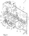
- reference number 1 denotes as a whole a rack-type dishwashing machine particularly adapted to rapidly wash up and rinse a succession of known dishwasher racks 100 each accommodating some dishware, cutlery or the like.
- the dishwashing machine 1 basically comprises: a preferably substantially parallelepiped-shaped, boxlike outer casing 2 which is provided with a preferably substantially rectilinear, pass-through tunnel 3 extending preferably substantially horizontally within the outer casing 2; and a preferably electrically-powered, linear conveyor 4 adapted to advance a succession of dishwasher racks 100 along the pass-through tunnel 3.
- the dishwashing machine 1 preferably includes: a main washing unit 5 which is adapted to wash up with a specific washing liquid and subsequently rinse the contents of each dishwasher rack 100 travelling inside the pass-through tunnel 3; and optionally also one or more auxiliary modular units which are discrete from washing unit 5 and are coupled to the washing unit 5, either upstream or downstream of the washing unit 5.
- the dishwashing machine 1 is preferably divided into a number of discrete modular units coupled to one another, so as to make up the pass-through tunnel 3, and to be crossed in succession by the dishwasher racks 100 travelling inside the pass-through tunnel 3.
- these one or more auxiliary modular units additionally include one or more pre-wash units 6 (one in the example shown) and/or a drying unit 7.
- the one or more pre-wash units 6 are arranged upstream of the washing unit 5, preferably adjoined to one another, and are adapted to wash up, preferably with cold or warm water, the contents of each dishwasher rack 100 travelling inside the pass-through tunnel 3.
- the drying unit 7, in turn, is arranged downstream of the washing unit 5, preferably adjoined to the latter, and is adapted to rapidly dry the contents of each dishwasher rack 100 travelling inside the pass-through tunnel 3.
- the linear conveyor 4 is furthermore a rollers conveyor or a twin chain conveyor.
- the portion of pass-through tunnel 3 preferably extending inside/delimited by the washing unit 5 is additionally divided into one or more washing sections 8 (one in the example shown) and one or more rinsing sections 9 (one in the example shown) arranged one downstream the other, so as to be crossed in succession by each dishwasher rack 100 travelling inside the pass-through tunnel 3.
- washing liquid is preferably a mixture of hot water and one or more detergent agents, and the temperature of the washing liquid preferably ranges between 60°C and 70°C.
- a number of high-pressure jets of a hot rinsing liquid are directed towards the dishwasher rack 100 momentarily travelling inside the rinsing section 9, so as to remove any residual of washing liquid from the dishware placed inside said dishwasher rack 100 and preferably also sanitize the same dishware.
- the rinsing liquid is preferably hot water or a mixture of hot water and one or more rinsing agents, and the temperature of the washing liquid preferably ranges between 70°C and 90°C
- the dishwashing machine 1 preferably comprises, inside the washing section 8 of tunnel 3: a first, relatively large, preferably rectangular-shaped, catchment sink 10 which is arranged on the bottom of tunnel 3 so as to collect and accumulate the washing liquid trickling down from the dishwasher rack 100 momentarily traveling inside the washing section 8; and a number of washing nozzles 11 which are arranged above the catchment sink 10, preferably above and beneath the moving path P of the dishwasher racks 100, and are oriented so as to direct the corresponding jets of washing liquid towards the dishwasher rack 100 momentarily traveling inside the washing section 8.
- a first, relatively large, preferably rectangular-shaped, catchment sink 10 which is arranged on the bottom of tunnel 3 so as to collect and accumulate the washing liquid trickling down from the dishwasher rack 100 momentarily traveling inside the washing section 8
- a number of washing nozzles 11 which are arranged above the catchment sink 10, preferably above and beneath the moving path P of the dishwasher racks 100, and are oriented so as to direct the corresponding jets of washing liquid towards the dishwasher rack 100 momentari
- the dishwashing machine 1 additionally comprises a washing-liquid feed line 12 which is adapted to feed the washing liquid accumulated into the catchment sink 10 towards the washing nozzles 11 with a given pressure preferably ranging between 1,5 and 3 bars.
- the feed line 12 preferably includes: a preferably electrically-powered, circulating pump 13 which sucks the washing liquid from the catchment sink 10, and feeds said washing liquid to the washing nozzles 11, preferably with a pressure ranging between 1,5 and 3 bars; and optionally also a filtering assembly 14 which is located upstream of the suction mouth of circulating pump 13, and is structured to hold/block almost any solid contaminants in suspension in the washing liquid directed towards the circulating pump 13, such as relatively big foodstuff particulates and the like.
- the filtering assembly 14 is furthermore fitted/accommodated, preferably in manually removable manner, into a drain sump 15 present on the bottom of catchment sink 10.
- the circulating pump 13, in turn, is preferably connected to the drain sump 15 for sucking the washing liquid from the inside of drain sump 15.
- the dishwashing machine 1 additionally comprises: a heating device 16 capable of heating up the washing liquid contained into the catchment sink 10; and preferably also a temperature sensor 17 capable of determining the current temperature of the washing liquid contained into the catchment sink 10.
- the heating device 16 preferably basically comprises: one or more resistors which are located inside the catchment sink 10, preferably close to the bottom of the latter; and an electric power unit (not shown) that supplies electric current to the resistors, preferably while controlling the value of said electric current on the basis of the electronic signals of the temperature sensor 17.
- the dishwashing machine 1 is moreover provided with an overflow assembly 18 which is fitted or incorporated into the catchment sink 10 and is structured to automatically drain, from catchment sink 10, the washing liquid exceeding a given maximum level and to channel said washing liquid in excess towards a drain piping 19 preferably communicating with an external sewage system.
- the dishwashing machine 1 additionally comprises: a level sensor 20 capable of determining the current level of the washing liquid contained into the catchment sink 10; and/or a preferably electrically-operated, on-off valve 21 connecting the catchment sink 10 to the drain piping 19 for allowing selective drain of the washing liquid of catchment sink 10 towards the drain piping 19, thus to selectively empty the catchment sink 10.
- a level sensor 20 capable of determining the current level of the washing liquid contained into the catchment sink 10
- a preferably electrically-operated, on-off valve 21 connecting the catchment sink 10 to the drain piping 19 for allowing selective drain of the washing liquid of catchment sink 10 towards the drain piping 19, thus to selectively empty the catchment sink 10.
- the on-off valve 21 preferably connects the drain sump 15 of catchment sink 10 to the drain piping 19 of dishwashing machine 1.
- the dishwashing machine 1 inside the rinsing section 9 of tunnel 3 the dishwashing machine 1 additionally preferably comprises: a second and a third, preferably rectangular-shaped, catchment sinks 22 and 23 which are arranged on the bottom of tunnel 3 one downstream and adjacent the other, so as to separately collect and accumulate the washing liquid trickling down from the dishwasher rack 100 momentarily traveling above the same catchment sinks 22 and 23; a number of final rinsing nozzles 24 which are arranged above catchment sink 23, i.e.
- the catchment sink farthest from catchment sink 10 preferably above and beneath the moving path of the dishwasher racks 100, and are oriented so as to direct the corresponding jets of rinsing liquid towards the dishwasher rack 100 momentarily traveling inside the rinsing section 9, above the same catchment sink 23; and a first rinsing-liquid feed line 25 adapted to feed the rinsing liquid towards the final rinsing nozzles 24 with a given pressure preferably ranging between 1,5 and 3 bars.
- the dishwashing machine 1 preferably comprises a boiler 26 which receives the fresh water preferably from the water mains, and is adapted to continuously heat up said fresh water at a given temperature preferably above 80°C; and the feed line 25 is preferably adapted to feed/channel the hot water of the boiler 26 towards the final rinsing nozzles 24 with a given pressure preferably ranging between 1,5 and 3 bars, optionally while also mixing one or more rinsing agents to the hot water flowing towards the final rinsing nozzles 24.
- the boiler 26 is preferably an air-tight closed container that preferably receives pressurized fresh water with a given pressure preferably ranging between 1,5 and 3 bars, from a second, preferably electrically-powered, circulating pump 27 which, in turn, sucks the fresh water from an air-gap container 28 that receives a flow of, preferably cold, fresh water from the water mains.
- the air-gap container 28 is connected/connectable to the water mains via a fresh water supply line, and this fresh water supply line preferably includes a preferably electrically-operated, on-off valve 29.
- the boiler 26 additionally includes a temperature sensor 30 capable of determining the current temperature of the fresh water contained into the boiler 26.
- the dishwashing machine 1 is preferably additionally provided with a recirculation line 31 which channels part of the fresh water coming out from the delivery mouth of circulation pump 27, back towards the air-gap container 28.
- This recirculation line 31 preferably includes a flowrate reducer.
- the air-gap container 28 in turn, preferably comprises: an open-to-air water tank 32 wherein the cold fresh water arriving from the water mains accumulates; and optionally also an overflow assembly 33 which is fitted/incorporated into the water tank 32 and is structured to automatically drain, from water tank 32, the fresh water exceeding a given maximum level and channel said fresh water towards the drain piping 19.
- the air-gap container 28 preferably includes: a temperature sensor 34 capable of determining the current temperature of the fresh water contained into the water tank 32; and/or a level sensor 35 capable of determining the current level of the fresh water contained into the same water tank 32.
- the dishwashing machine 1 moreover comprises, between boiler 26 and circulating pump 27: a one-way valve 36 or other back-flow prevention device which allows the pressurized fresh water to solely flow from circulating pump 27 to boiler 26; and optionally also an energy saving device 37 which is adapted to pre-heat the pressurized fresh water flowing towards the boiler 26.
- the energy saving device 37 preferably, though not necessarily, consists in one or more heat exchangers capable of transferring heat from the hot air previously used for drying the dishes inside the drying unit 7, to the pressurized fresh water flowing towards the boiler 26.
- a further temperature sensor 38 is arranged between the energy saving device 37 and the boiler 26. This temperature sensor is capable of determining the current temperature of the fresh water entering into the boiler 26.
- the rinsing-liquid feed line 25 in turn preferably includes: an electronically-controlled, solenoid valve 40 capable of regulating the flowrate of the hot rinsing liquid, or better the hot fresh water possibly mixed with rinsing agent/s, directed towards the final rinsing nozzles 24; and optionally also a flow meter 41 capable of determining the current flowrate of the hot rinsing liquid, i.e. the hot fresh water possibly mixed with rinsing agent/s, directed towards the final rinsing nozzles 24.
- the dishwashing machine 1, or better the main washing unit 5 of dishwashing machine 1 preferably additionally comprises: a number of intermediate rinsing nozzles 42 which are substantially vertically aligned above the border between catchment sink 22 and catchment sink 23, preferably above and beneath the moving path P of the dishwasher racks 100, and are oriented so as to direct the corresponding jets of rinsing liquid towards the dishwasher rack 100 momentarily located inside the rinsing section 9, astride the catchment sinks 22 and 23; and a second rinsing-liquid feed line 43 which is adapted to feed the hot rinsing liquid accumulated into the catchment sink 23 towards the intermediate rinsing nozzles 42 with a given pressure preferably ranging between 1,5 and 3 bars.
- the hot rinsing liquid projected by the intermediate rinsing nozzles 42 after bumping into the contents of dishwasher rack 100, trickles partly inside catchment sink 22 and partly inside catchment sink 23.
- the feed line 43 preferably includes: a preferably electrically-powered, circulating pump 44 which sucks the rinsing liquid from the catchment sink 23, and feeds said rinsing liquid to the intermediate rinsing nozzles 42 preferably with a pressure ranging between 1,5 and 3 bars; and optionally also a filtering assembly 45 which is located upstream of the suction mouth of circulating pump 44, and is structured to hold/block almost any solid contaminants in suspension in the hot rinsing liquid directed towards the circulating pump 44.
- a preferably electrically-powered, circulating pump 44 which sucks the rinsing liquid from the catchment sink 23, and feeds said rinsing liquid to the intermediate rinsing nozzles 42 preferably with a pressure ranging between 1,5 and 3 bars
- a filtering assembly 45 which is located upstream of the suction mouth of circulating pump 44, and is structured to hold/block almost any solid contaminants in suspension in the hot rinsing liquid directed towards the circulating pump 44.
- catchment sink 23 preferably has, on the bottom, a drain sump 46 and the circulating pump 44 of feed line 43 preferably sucks the rinsing liquid from the inside of drain sump 46.
- the filtering assembly 45 is furthermore fitted/accommodated, preferably in manually removable manner, into drain sump 46.
- rinsing-liquid feed line 43 preferably additionally includes a flow meter 47 capable of determining the current flowrate of the hot rinsing liquid, or better of the hot fresh water possibly mixed with rinsing agent/s, directed towards the intermediate rinsing nozzles 42.
- the dishwashing machine 1 preferably additionally comprises a second drain line 48 which connects the catchment sink 23 to the drain piping 19 and which preferably includes a preferably electrically-operated, on-off valve 49 that allows selective drain of the rinsing liquid of catchment sink 23 into drain piping 19, thus to selectively empty the catchment sink 23.
- the drain line 48 preferably connects the drain sump 46 of catchment sink 23 to the drain piping 19.
- the on-off valve 49 is preferably interposed between the drain sump 46 of catchment sink 23 and the drain piping 19.
- the dishwashing machine 1, or better the washing unit 5 of dishwashing machine 1 additionally includes a second overflow assembly 50 which is fitted or incorporated into catchment sink 23 and is structured to automatically channel, from catchment sink 23 to catchment sink 22, the rinsing liquid contained into catchment sink 23 and exceeding a given threshold level.
- a second overflow assembly 50 which is fitted or incorporated into catchment sink 23 and is structured to automatically channel, from catchment sink 23 to catchment sink 22, the rinsing liquid contained into catchment sink 23 and exceeding a given threshold level.
- catchment sink 23 is fluidically connected to catchment sink 22 via an overflow assembly 50 which is structured to automatically channel, from catchment sink 23 to catchment sink 22, the rinsing liquid contained into catchment sink 23 and exceeding a given threshold level.
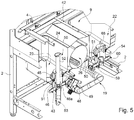
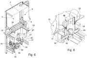
- this overflow assembly 50 additionally incudes: a connecting pipe 51 that puts catchment sink 23 in permanent fluid communication with catchment sink 22, so as to allow the rinsing liquid to freely flow from catchment sink 23 to catchment sink 22; and an overflow member 52 which is fitted or incorporated into catchment sink 23, is coupled to connecting pipe 51 in watertight and easy manually detachable manner, and is structured to automatically channel, into connecting pipe 51, the rinsing liquid contained into catchment sink 23 and exceeding said threshold level.
- connecting pipe 51 preferably branches off from the drain sump 46 of catchment sink 23, and the overflow member 52 is preferably coupled in manually detachable manner to connecting pipe 51 within drain sump 46.
- catchment sink 23 furthermore directly communicates with the drain piping 19 via an auxiliary drain line 53 that branches off from the drain sump 46, and the overflow member 52 is structured to additionally obstruct/block up said auxiliary drain line 53 when coupled to connecting pipe 51.
- the overflow member 52 is detached from connecting pipe 51, the rinsing liquid contained into catchment sink 23 is allowed to freely flow into drain piping 19 via drain line 53.
- catchment sink 22 preferably has, on the bottom, a drain sump 54, and connecting pipe 51 preferably extends from drain sump 46 to drain sump 54 so as to put the drain sumps 46 and 53 in fluid communication to one another.
- on-off valve 49 is set in the opened position and/or the overflow member 52 is detached from connecting pipe 51, the rinsing liquid contained into both catchment sinks 22 and 23 is allowed to freely flow into drain piping 19.
- the filtering assembly 45 preferably includes a cup-shaped member which has a water-permeable structure, and is fitted in watertight and manually removable manner into the upper mouth of drain sump 46, to close the drain sump 46.
- Connecting pipe 51 in turn, preferably branches off directly from a preferably substantially vertically-oriented, tubular section/extension 46a formed in the bottom of drain sump 46, and the overflow member 52 preferably comprises, or better consists of, a straight pipe segment which extends substantially vertically, preferably engages in pass-through manner the filtering assembly 45, and is finally fitted in watertight and removable manner directly into the upper mouth of tubular section 46a.
- tubular section 46a of drain sump 46 is preferably substantially cylindrical in shape, and cross-section of straight pipe segment 52 is preferably substantially complementary in shape to that of tubular section 46a.
- the lower mouth of tubular section 46a furthermore, directly communicates with the auxiliary drain line 53, and the lower end 52a of pipe segment 52 is preferably shaped to obstruct in watertight manner the inside of tubular section 46a, underneath/downstream of the joining point with connecting pipe 51, so as to be capable of channelling the rinsing liquid solely towards connecting pipe 51.
- the dishwashing machine 1, or better the main washing unit 5 of dishwashing machine 1 moreover includes an auxiliary overflow assembly 55 which is preferably fitted/incorporated into catchment sink 23 and is structured to automatically drain, from catchment sink 23, the rinsing liquid exceeding a given maximum level and to channel the rinsing liquid in excess towards the drain piping 19.
- this maximum level is furthermore greater/higher that the aforesaid threshold level.
- the dishwashing machine 1, or better the main washing unit 5 of dishwashing machine 1 preferably additionally comprises: a number of pre-rinsing nozzles 58 which are vertically aligned above the catchment sink 22, preferably above and beneath the moving path P of the dishwasher racks 100, and are oriented so as to direct the corresponding jets of rinsing liquid towards the dishwasher rack 100 momentarily travelling inside the rinsing section 9, above the catchment sink 22; and, preferably, a third rinsing-liquid feed line 59 which is adapted to feed the rinsing liquid accumulated into the catchment sink 22 towards the pre-rinsing nozzles 58 and additionally also back towards the catchment sink 23, with a given pressure, preferably ranging between 1,5 and 3 bars.
- catchment sink 22 is in, preferably permanent, fluid communication with catchment sink 23 via the overflow assembly 50, and the rinsing-liquid feed line 59 is adapted to, preferably continuously, channel part of the rinsing liquid accumulated into catchment sink 22 back towards catchment sink 23.
- the feed line 59 is furthermore structured to feed the rinsing liquid towards the pre-rinsing nozzles 58 and towards the catchment sink 23 with a given flowrate-partition ratio.
- the flowrate of the rinsing liquid directed towards catchment sink 23 is preferably at least twice greater than the flowrate of rinsing liquid directed towards catchment sink 23 the pre-rinsing nozzles 58.
- the dishwashing machine 1, or better the main washing unit 5 of dishwashing machine 1 preferably includes a rinsing-liquid transfer line 60 which is adapted to move/feed the rinsing liquid accumulating into the catchment sink 22 directly towards the catchment sink 10.
- the dishwashing machine 1 moreover comprises: a heating device 61 capable of heating up the rinsing liquid contained into the catchment sink 22; and optionally also a temperature sensor 62 which is capable of determining the current temperature of the rinsing liquid contained into the catchment sink 22.
- the heating device 61 preferably basically includes one or more resistors which are located inside the catchment sink 22, preferably close to the bottom of the latter; and an electric power unit (not shown) that supplies electric current to the resistors, preferably while controlling the value of said electric current on the basis of the electronic signals of the temperature sensor 62.
- the dishwashing machine 1 is additionally provided with a further level sensor 63 capable of determining the current level of the rinsing liquid contained into the catchment sink 22.
- the rinsing-liquid feed line 59 preferably includes: a preferably electrically-powered, circulating pump 65 which sucks the rinsing liquid from catchment sink 22, and feeds said rinsing liquid to both the pre-rinsing nozzles 58 and the catchment sink 23, preferably with a pressure ranging between 1,5 and 3 bars; and optionally also a filtering assembly 66 which is located upstream of the suction mouth of circulating pump 65, and is structured to hold/block almost any solid contaminants in suspension in the rinsing liquid directed towards the circulating pump 65.
- the filtering assembly 66 is preferably fitted/accommodated, preferably in manually removable manner, into the upper mouth of drain sump 54 of catchment sink 22, and the circulating pump 65 of rinsing-liquid feed line 59 sucks the rinsing liquid directly from the drain sump 54.
- the filtering assembly 66 preferably comprises a cup-shaped member which has a water-permeable structure and is fitted in watertight and manually removable manner into the upper mouth of drain sump 65 to close the drain sump 65.
- the rinsing-liquid feed line 59 additionally includes a one-way valve, an air-gap assembly or another type of back-flow prevention device which is preferably located along the pipe channelling the rinsing liquid from circulating pump 65 back to catchment sink 23, and is adapted to prevent the rinsing liquid to flow back to circulating pump 65.
- the rinsing-liquid feed line 59 also includes a supplementary nozzle 67 which is preferably located on a sidewall of catchment sink 23, preferably below the threshold level maintained by the overflow assembly 50, and is adapted to squirt/ pour the rinsing liquid arriving from circulating pump 65 directly into catchment sink 23, preferably towards the bottom of catchment sink 23.
- a supplementary nozzle 67 which is preferably located on a sidewall of catchment sink 23, preferably below the threshold level maintained by the overflow assembly 50, and is adapted to squirt/ pour the rinsing liquid arriving from circulating pump 65 directly into catchment sink 23, preferably towards the bottom of catchment sink 23.
- the rinsing-liquid transfer line 60 comprises: a preferably electrically-powered, circulating pump 68 which sucks the rinsing liquid from catchment sink 22, and feeds said rinsing liquid directly to catchment sink 10, preferably with a pressure ranging between 1,5 and 3 bars; and optionally also a filtering assembly which is located upstream of the suction mouth of circulating pump 68, and is structured to hold/block solid contaminants in suspension in the rinsing liquid directed towards the circulating pump 68.
- circulating pump 68 preferably sucks the rinsing liquid from the drain sump 54, thus rinsing-liquid feed line 59 and rinsing-liquid transfer line 60 share the filtering assembly 66.
- the rinsing-liquid transfer line 60 additionally includes a one-way valve, an air-gap assembly or another type of back-flow prevention device which is preferably located along the pipe channelling the rinsing liquid from circulating pump 68 to catchment sink 10, and is adapted to prevent the rinsing liquid to flow back to circulating pump 68.
- the rinsing-liquid transfer line 60 preferably also includes a supplementary nozzle 69 which is preferably located on a sidewall of catchment sink 10, preferably below the maximum level permitted by the overflow assembly 18, and is adapted to squirt/pour the rinsing liquid arriving from circulating pump 68 directly into catchment sink 10, preferably towards the bottom of catchment sink 10.
- a supplementary nozzle 69 which is preferably located on a sidewall of catchment sink 10, preferably below the maximum level permitted by the overflow assembly 18, and is adapted to squirt/pour the rinsing liquid arriving from circulating pump 68 directly into catchment sink 10, preferably towards the bottom of catchment sink 10.
- the dishwashing machine 1, or better the main washing unit 5 of dishwashing machine 1 additionally comprises an auxiliary fresh-water supply line 70 which is connected/connectable to the water mains or to an alternative hot-water external water source, and is structured to selectively and independently channel a flow of preferably hot, fresh water towards, respectively, catchment sink 10 and catchment sink 22, to selectively fill up any one of the two catchment sinks 10 and 22.
- auxiliary fresh-water supply line 70 which is connected/connectable to the water mains or to an alternative hot-water external water source, and is structured to selectively and independently channel a flow of preferably hot, fresh water towards, respectively, catchment sink 10 and catchment sink 22, to selectively fill up any one of the two catchment sinks 10 and 22.
- This auxiliary fresh-water supply line 70 preferably includes: a common measuring device 71 capable of detecting the temperature and/or flowrate of the preferably hot, fresh water arriving from the water mains or other external water source and directed towards any one of the two catchment sinks 10 and 22; and two preferably electrically-operated, distinct on-off valves 72 and 73 each capable of controlling the flow of the preferably hot, fresh water towards a respective catchment sink 10, 22.
- the auxiliary fresh-water supply line 70 additionally includes, for both catchment sink 10 and catchment sink 22, a respective one-way valve, an air-gap assembly or another type of back-flow prevention device which is preferably located along the pipe channelling the preferably hot, fresh water towards the catchment sink 10, 22, and is adapted to prevent the fresh water to flow back to the water mains or other external water source.
- the fresh-water supply line 70 preferably additionally includes: a first supplementary nozzle 74 which is preferably located on a sidewall of catchment sink 10, preferably above the maximum level permitted by the overflow assembly 18, and is adapted to squirt/pour the fresh water flowing along supply line 70 directly into catchment sink 10, preferably towards the bottom of catchment sink 10; and/or a second supplementary nozzle which is preferably located on a sidewall of catchment sink 22, preferably above the threshold level permitted by the overflow assembly 50 of catchment sink 22, and is adapted to squirt/pour the fresh water flowing along supply line 70 directly into catchment sink 22, preferably towards the bottom of catchment sink 22.
- a first supplementary nozzle 74 which is preferably located on a sidewall of catchment sink 10, preferably above the maximum level permitted by the overflow assembly 18, and is adapted to squirt/pour the fresh water flowing along supply line 70 directly into catchment sink 10, preferably towards the bottom of catchment sink 10
- a second supplementary nozzle which is preferably
- the dishwashing machine 1 also includes a main electronic control unit (not shown in the figures) which controls the various electric/electronic devices so as to automatically perform the washing program selected by the user.
- a main electronic control unit (not shown in the figures) which controls the various electric/electronic devices so as to automatically perform the washing program selected by the user.
- the overflow assembly 50 automatically channels from catchment sink 23 to catchment sink 22, the rinsing liquid contained into catchment sink 23 and exceeding said threshold level.
- the unidirectional flow of the rinsing liquid from catchment sink 23 to catchment sink 22 obviously continues until the level of the rinsing liquid in catchment sink 23 remains above the threshold level and until the level of the rinsing liquid in catchment sink 22 equalizes the level of the rinsing liquid inside catchment sink 23.
- rinsing-liquid feed line 59 and rinsing-liquid transfer line 60 preferably continuously, keep the level of the rinsing liquid contained into catchment sink 22 below the level of the rinsing liquid inside catchment sink 23.
- the overflow assembly 50 unidirectionally channels the rinsing liquid exceeding the overflow threshold from catchment sink 23 to catchment sink 22, whereas rinsing-liquid feed line 59 channels the rinsing liquid back into catchment sink 23.
- Overflow assembly 50 and rinsing-liquid feed line 59 therefore, operate a recirculation of the rinsing liquid between catchment sinks 22 and 23.
- the level of the rinsing liquid contained into catchment sink 23 fluctuates about the threshold level, whereas the level of the rinsing liquid contained into catchment sink 22 is allowed to freely vary, with no correlation with the level of the rinsing liquid contained into catchment sink 23.
- the electronic control unit automatically opens the on-off valve 49 to drain the rinsing liquid from catchment sink 23 and so stop the outflow of rinsing liquid towards catchment sink 22.
- the pass-through tunnel 3 may have one or more bends.
- the dishwashing machine 1 furthermore may additionally include a descaling system.
Landscapes
- Washing And Drying Of Tableware (AREA)
Priority Applications (1)
| Application Number | Priority Date | Filing Date | Title |
|---|---|---|---|
| EP17158124.2A EP3366185B1 (de) | 2017-02-27 | 2017-02-27 | Geschirrspülmaschine |
Applications Claiming Priority (1)
| Application Number | Priority Date | Filing Date | Title |
|---|---|---|---|
| EP17158124.2A EP3366185B1 (de) | 2017-02-27 | 2017-02-27 | Geschirrspülmaschine |
Publications (2)
| Publication Number | Publication Date |
|---|---|
| EP3366185A1 true EP3366185A1 (de) | 2018-08-29 |
| EP3366185B1 EP3366185B1 (de) | 2019-10-16 |
Family
ID=58185405
Family Applications (1)
| Application Number | Title | Priority Date | Filing Date |
|---|---|---|---|
| EP17158124.2A Active EP3366185B1 (de) | 2017-02-27 | 2017-02-27 | Geschirrspülmaschine |
Country Status (1)
| Country | Link |
|---|---|
| EP (1) | EP3366185B1 (de) |
Citations (3)
| Publication number | Priority date | Publication date | Assignee | Title |
|---|---|---|---|---|
| DE4100164C1 (de) * | 1991-01-05 | 1992-04-30 | Deutsche Lufthansa Ag, 5000 Koeln, De | |
| EP2510863A1 (de) * | 2011-04-11 | 2012-10-17 | Chemische Fabrik Dr. Weigert GmbH & Co. KG | Variable Direktbesprühung |
| EP2772178A1 (de) * | 2013-02-28 | 2014-09-03 | Comenda Ali S.p.A. | Verbessertes Spülmodul mit Endspülung mit entmineralisiertem Wasser, zugehöriges verbessertes Spülverfahren und Tunnel-Geschirrspülmaschine mit solch einem verbesserten Spülmodul |
-
2017
- 2017-02-27 EP EP17158124.2A patent/EP3366185B1/de active Active
Patent Citations (3)
| Publication number | Priority date | Publication date | Assignee | Title |
|---|---|---|---|---|
| DE4100164C1 (de) * | 1991-01-05 | 1992-04-30 | Deutsche Lufthansa Ag, 5000 Koeln, De | |
| EP2510863A1 (de) * | 2011-04-11 | 2012-10-17 | Chemische Fabrik Dr. Weigert GmbH & Co. KG | Variable Direktbesprühung |
| EP2772178A1 (de) * | 2013-02-28 | 2014-09-03 | Comenda Ali S.p.A. | Verbessertes Spülmodul mit Endspülung mit entmineralisiertem Wasser, zugehöriges verbessertes Spülverfahren und Tunnel-Geschirrspülmaschine mit solch einem verbesserten Spülmodul |
Also Published As
| Publication number | Publication date |
|---|---|
| EP3366185B1 (de) | 2019-10-16 |
Similar Documents
| Publication | Publication Date | Title |
|---|---|---|
| CA2671813C (en) | Warewasher with water energy recovery system | |
| EP2954111B1 (de) | Wäschewaschmaschine | |
| US9903064B2 (en) | Laundry washing machine | |
| US10835099B2 (en) | Dishwashing machine | |
| ATE308267T1 (de) | Geschirrspülmaschine mit mitteln zur reduzierung des energie- und wasserverbrauchs | |
| KR102280246B1 (ko) | 음료 공급 장치 | |
| CA2698320A1 (en) | Dishwasher with conductivity measurement | |
| AU2017281507B2 (en) | Operating method of a laundry washing machine and laundry washing machine implementing such method | |
| CA2552011C (en) | Conveyor dishwasher and operating method for same | |
| EP2818089B1 (de) | Geschirrspülmaschine der Fördererart | |
| EP3366185B1 (de) | Geschirrspülmaschine | |
| EP3234253B1 (de) | Wäschewaschmaschine | |
| CN217310192U (zh) | 一种商用卧式洗碗机 | |
| JP6026253B2 (ja) | 熱源機およびドレン中和ユニット | |
| JP2013244121A (ja) | 茹で器の給排水装置 | |
| RU2494668C2 (ru) | Устройство с контролем уровня для отделения загрязняющих примесей | |
| CN117652982A (zh) | 一种洗碗机 | |
| EP3424400B1 (de) | Verfahren zum betrieb einer professionellen tunnelgeschirrspülmaschine | |
| JPS631969Y2 (de) | ||
| WO2025253341A1 (en) | Milk module for producing milk-based beverages | |
| JP6403588B2 (ja) | 洗浄機 | |
| CN108289587A (zh) | 器皿清洗机怠速系统和方法 | |
| JPH0737094Y2 (ja) | 浴槽排水装置 | |
| JPH0337025A (ja) | 食器洗浄機 |
Legal Events
| Date | Code | Title | Description |
|---|---|---|---|
| PUAI | Public reference made under article 153(3) epc to a published international application that has entered the european phase |
Free format text: ORIGINAL CODE: 0009012 |
|
| STAA | Information on the status of an ep patent application or granted ep patent |
Free format text: STATUS: THE APPLICATION HAS BEEN PUBLISHED |
|
| AK | Designated contracting states |
Kind code of ref document: A1 Designated state(s): AL AT BE BG CH CY CZ DE DK EE ES FI FR GB GR HR HU IE IS IT LI LT LU LV MC MK MT NL NO PL PT RO RS SE SI SK SM TR |
|
| AX | Request for extension of the european patent |
Extension state: BA ME |
|
| STAA | Information on the status of an ep patent application or granted ep patent |
Free format text: STATUS: REQUEST FOR EXAMINATION WAS MADE |
|
| 17P | Request for examination filed |
Effective date: 20190228 |
|
| RBV | Designated contracting states (corrected) |
Designated state(s): AL AT BE BG CH CY CZ DE DK EE ES FI FR GB GR HR HU IE IS IT LI LT LU LV MC MK MT NL NO PL PT RO RS SE SI SK SM TR |
|
| RIC1 | Information provided on ipc code assigned before grant |
Ipc: A47L 15/00 20060101AFI20190328BHEP |
|
| GRAP | Despatch of communication of intention to grant a patent |
Free format text: ORIGINAL CODE: EPIDOSNIGR1 |
|
| STAA | Information on the status of an ep patent application or granted ep patent |
Free format text: STATUS: GRANT OF PATENT IS INTENDED |
|
| INTG | Intention to grant announced |
Effective date: 20190517 |
|
| GRAS | Grant fee paid |
Free format text: ORIGINAL CODE: EPIDOSNIGR3 |
|
| GRAA | (expected) grant |
Free format text: ORIGINAL CODE: 0009210 |
|
| STAA | Information on the status of an ep patent application or granted ep patent |
Free format text: STATUS: THE PATENT HAS BEEN GRANTED |
|
| AK | Designated contracting states |
Kind code of ref document: B1 Designated state(s): AL AT BE BG CH CY CZ DE DK EE ES FI FR GB GR HR HU IE IS IT LI LT LU LV MC MK MT NL NO PL PT RO RS SE SI SK SM TR |
|
| REG | Reference to a national code |
Ref country code: GB Ref legal event code: FG4D |
|
| REG | Reference to a national code |
Ref country code: CH Ref legal event code: EP |
|
| REG | Reference to a national code |
Ref country code: DE Ref legal event code: R096 Ref document number: 602017007746 Country of ref document: DE |
|
| REG | Reference to a national code |
Ref country code: IE Ref legal event code: FG4D |
|
| REG | Reference to a national code |
Ref country code: AT Ref legal event code: REF Ref document number: 1190479 Country of ref document: AT Kind code of ref document: T Effective date: 20191115 |
|
| REG | Reference to a national code |
Ref country code: NL Ref legal event code: MP Effective date: 20191016 |
|
| REG | Reference to a national code |
Ref country code: LT Ref legal event code: MG4D |
|
| REG | Reference to a national code |
Ref country code: AT Ref legal event code: MK05 Ref document number: 1190479 Country of ref document: AT Kind code of ref document: T Effective date: 20191016 |
|
| PG25 | Lapsed in a contracting state [announced via postgrant information from national office to epo] |
Ref country code: NO Free format text: LAPSE BECAUSE OF FAILURE TO SUBMIT A TRANSLATION OF THE DESCRIPTION OR TO PAY THE FEE WITHIN THE PRESCRIBED TIME-LIMIT Effective date: 20200116 Ref country code: PT Free format text: LAPSE BECAUSE OF FAILURE TO SUBMIT A TRANSLATION OF THE DESCRIPTION OR TO PAY THE FEE WITHIN THE PRESCRIBED TIME-LIMIT Effective date: 20200217 Ref country code: BG Free format text: LAPSE BECAUSE OF FAILURE TO SUBMIT A TRANSLATION OF THE DESCRIPTION OR TO PAY THE FEE WITHIN THE PRESCRIBED TIME-LIMIT Effective date: 20200116 Ref country code: FI Free format text: LAPSE BECAUSE OF FAILURE TO SUBMIT A TRANSLATION OF THE DESCRIPTION OR TO PAY THE FEE WITHIN THE PRESCRIBED TIME-LIMIT Effective date: 20191016 Ref country code: LV Free format text: LAPSE BECAUSE OF FAILURE TO SUBMIT A TRANSLATION OF THE DESCRIPTION OR TO PAY THE FEE WITHIN THE PRESCRIBED TIME-LIMIT Effective date: 20191016 Ref country code: NL Free format text: LAPSE BECAUSE OF FAILURE TO SUBMIT A TRANSLATION OF THE DESCRIPTION OR TO PAY THE FEE WITHIN THE PRESCRIBED TIME-LIMIT Effective date: 20191016 Ref country code: SE Free format text: LAPSE BECAUSE OF FAILURE TO SUBMIT A TRANSLATION OF THE DESCRIPTION OR TO PAY THE FEE WITHIN THE PRESCRIBED TIME-LIMIT Effective date: 20191016 Ref country code: AT Free format text: LAPSE BECAUSE OF FAILURE TO SUBMIT A TRANSLATION OF THE DESCRIPTION OR TO PAY THE FEE WITHIN THE PRESCRIBED TIME-LIMIT Effective date: 20191016 Ref country code: PL Free format text: LAPSE BECAUSE OF FAILURE TO SUBMIT A TRANSLATION OF THE DESCRIPTION OR TO PAY THE FEE WITHIN THE PRESCRIBED TIME-LIMIT Effective date: 20191016 Ref country code: GR Free format text: LAPSE BECAUSE OF FAILURE TO SUBMIT A TRANSLATION OF THE DESCRIPTION OR TO PAY THE FEE WITHIN THE PRESCRIBED TIME-LIMIT Effective date: 20200117 Ref country code: LT Free format text: LAPSE BECAUSE OF FAILURE TO SUBMIT A TRANSLATION OF THE DESCRIPTION OR TO PAY THE FEE WITHIN THE PRESCRIBED TIME-LIMIT Effective date: 20191016 |
|
| PG25 | Lapsed in a contracting state [announced via postgrant information from national office to epo] |
Ref country code: HR Free format text: LAPSE BECAUSE OF FAILURE TO SUBMIT A TRANSLATION OF THE DESCRIPTION OR TO PAY THE FEE WITHIN THE PRESCRIBED TIME-LIMIT Effective date: 20191016 Ref country code: RS Free format text: LAPSE BECAUSE OF FAILURE TO SUBMIT A TRANSLATION OF THE DESCRIPTION OR TO PAY THE FEE WITHIN THE PRESCRIBED TIME-LIMIT Effective date: 20191016 Ref country code: IS Free format text: LAPSE BECAUSE OF FAILURE TO SUBMIT A TRANSLATION OF THE DESCRIPTION OR TO PAY THE FEE WITHIN THE PRESCRIBED TIME-LIMIT Effective date: 20200224 |
|
| PG25 | Lapsed in a contracting state [announced via postgrant information from national office to epo] |
Ref country code: AL Free format text: LAPSE BECAUSE OF FAILURE TO SUBMIT A TRANSLATION OF THE DESCRIPTION OR TO PAY THE FEE WITHIN THE PRESCRIBED TIME-LIMIT Effective date: 20191016 |
|
| REG | Reference to a national code |
Ref country code: DE Ref legal event code: R097 Ref document number: 602017007746 Country of ref document: DE |
|
| PG2D | Information on lapse in contracting state deleted |
Ref country code: IS |
|
| PG25 | Lapsed in a contracting state [announced via postgrant information from national office to epo] |
Ref country code: DK Free format text: LAPSE BECAUSE OF FAILURE TO SUBMIT A TRANSLATION OF THE DESCRIPTION OR TO PAY THE FEE WITHIN THE PRESCRIBED TIME-LIMIT Effective date: 20191016 Ref country code: EE Free format text: LAPSE BECAUSE OF FAILURE TO SUBMIT A TRANSLATION OF THE DESCRIPTION OR TO PAY THE FEE WITHIN THE PRESCRIBED TIME-LIMIT Effective date: 20191016 Ref country code: ES Free format text: LAPSE BECAUSE OF FAILURE TO SUBMIT A TRANSLATION OF THE DESCRIPTION OR TO PAY THE FEE WITHIN THE PRESCRIBED TIME-LIMIT Effective date: 20191016 Ref country code: RO Free format text: LAPSE BECAUSE OF FAILURE TO SUBMIT A TRANSLATION OF THE DESCRIPTION OR TO PAY THE FEE WITHIN THE PRESCRIBED TIME-LIMIT Effective date: 20191016 Ref country code: CZ Free format text: LAPSE BECAUSE OF FAILURE TO SUBMIT A TRANSLATION OF THE DESCRIPTION OR TO PAY THE FEE WITHIN THE PRESCRIBED TIME-LIMIT Effective date: 20191016 Ref country code: IS Free format text: LAPSE BECAUSE OF FAILURE TO SUBMIT A TRANSLATION OF THE DESCRIPTION OR TO PAY THE FEE WITHIN THE PRESCRIBED TIME-LIMIT Effective date: 20200216 |
|
| PLBE | No opposition filed within time limit |
Free format text: ORIGINAL CODE: 0009261 |
|
| STAA | Information on the status of an ep patent application or granted ep patent |
Free format text: STATUS: NO OPPOSITION FILED WITHIN TIME LIMIT |
|
| PG25 | Lapsed in a contracting state [announced via postgrant information from national office to epo] |
Ref country code: SM Free format text: LAPSE BECAUSE OF FAILURE TO SUBMIT A TRANSLATION OF THE DESCRIPTION OR TO PAY THE FEE WITHIN THE PRESCRIBED TIME-LIMIT Effective date: 20191016 Ref country code: SK Free format text: LAPSE BECAUSE OF FAILURE TO SUBMIT A TRANSLATION OF THE DESCRIPTION OR TO PAY THE FEE WITHIN THE PRESCRIBED TIME-LIMIT Effective date: 20191016 |
|
| 26N | No opposition filed |
Effective date: 20200717 |
|
| REG | Reference to a national code |
Ref country code: CH Ref legal event code: PL |
|
| REG | Reference to a national code |
Ref country code: BE Ref legal event code: MM Effective date: 20200229 |
|
| PG25 | Lapsed in a contracting state [announced via postgrant information from national office to epo] |
Ref country code: MC Free format text: LAPSE BECAUSE OF FAILURE TO SUBMIT A TRANSLATION OF THE DESCRIPTION OR TO PAY THE FEE WITHIN THE PRESCRIBED TIME-LIMIT Effective date: 20191016 Ref country code: LU Free format text: LAPSE BECAUSE OF NON-PAYMENT OF DUE FEES Effective date: 20200227 |
|
| PG25 | Lapsed in a contracting state [announced via postgrant information from national office to epo] |
Ref country code: CH Free format text: LAPSE BECAUSE OF NON-PAYMENT OF DUE FEES Effective date: 20200229 Ref country code: SI Free format text: LAPSE BECAUSE OF FAILURE TO SUBMIT A TRANSLATION OF THE DESCRIPTION OR TO PAY THE FEE WITHIN THE PRESCRIBED TIME-LIMIT Effective date: 20191016 Ref country code: LI Free format text: LAPSE BECAUSE OF NON-PAYMENT OF DUE FEES Effective date: 20200229 |
|
| PG25 | Lapsed in a contracting state [announced via postgrant information from national office to epo] |
Ref country code: FR Free format text: LAPSE BECAUSE OF NON-PAYMENT OF DUE FEES Effective date: 20200229 Ref country code: IE Free format text: LAPSE BECAUSE OF NON-PAYMENT OF DUE FEES Effective date: 20200227 |
|
| PG25 | Lapsed in a contracting state [announced via postgrant information from national office to epo] |
Ref country code: BE Free format text: LAPSE BECAUSE OF NON-PAYMENT OF DUE FEES Effective date: 20200229 |
|
| GBPC | Gb: european patent ceased through non-payment of renewal fee |
Effective date: 20210227 |
|
| PG25 | Lapsed in a contracting state [announced via postgrant information from national office to epo] |
Ref country code: GB Free format text: LAPSE BECAUSE OF NON-PAYMENT OF DUE FEES Effective date: 20210227 |
|
| PG25 | Lapsed in a contracting state [announced via postgrant information from national office to epo] |
Ref country code: TR Free format text: LAPSE BECAUSE OF FAILURE TO SUBMIT A TRANSLATION OF THE DESCRIPTION OR TO PAY THE FEE WITHIN THE PRESCRIBED TIME-LIMIT Effective date: 20191016 Ref country code: MT Free format text: LAPSE BECAUSE OF FAILURE TO SUBMIT A TRANSLATION OF THE DESCRIPTION OR TO PAY THE FEE WITHIN THE PRESCRIBED TIME-LIMIT Effective date: 20191016 Ref country code: CY Free format text: LAPSE BECAUSE OF FAILURE TO SUBMIT A TRANSLATION OF THE DESCRIPTION OR TO PAY THE FEE WITHIN THE PRESCRIBED TIME-LIMIT Effective date: 20191016 |
|
| PG25 | Lapsed in a contracting state [announced via postgrant information from national office to epo] |
Ref country code: MK Free format text: LAPSE BECAUSE OF FAILURE TO SUBMIT A TRANSLATION OF THE DESCRIPTION OR TO PAY THE FEE WITHIN THE PRESCRIBED TIME-LIMIT Effective date: 20191016 |
|
| P01 | Opt-out of the competence of the unified patent court (upc) registered |
Effective date: 20230526 |
|
| PGFP | Annual fee paid to national office [announced via postgrant information from national office to epo] |
Ref country code: DE Payment date: 20260218 Year of fee payment: 10 |
|
| PGFP | Annual fee paid to national office [announced via postgrant information from national office to epo] |
Ref country code: IT Payment date: 20260115 Year of fee payment: 10 |