EP3367699B1 - Lautsprecher fahrer surround - Google Patents
Lautsprecher fahrer surround Download PDFInfo
- Publication number
- EP3367699B1 EP3367699B1 EP18275027.3A EP18275027A EP3367699B1 EP 3367699 B1 EP3367699 B1 EP 3367699B1 EP 18275027 A EP18275027 A EP 18275027A EP 3367699 B1 EP3367699 B1 EP 3367699B1
- Authority
- EP
- European Patent Office
- Prior art keywords
- surround
- roll surface
- corrugations
- loudspeaker driver
- edge
- Prior art date
- Legal status (The legal status is an assumption and is not a legal conclusion. Google has not performed a legal analysis and makes no representation as to the accuracy of the status listed.)
- Active
Links
Images


Classifications
-
- H—ELECTRICITY
- H04—ELECTRIC COMMUNICATION TECHNIQUE
- H04R—LOUDSPEAKERS, MICROPHONES, GRAMOPHONE PICK-UPS OR LIKE ACOUSTIC ELECTROMECHANICAL TRANSDUCERS; ELECTRIC HEARING AIDS; PUBLIC ADDRESS SYSTEMS
- H04R9/00—Transducers of moving-coil, moving-strip, or moving-wire type
- H04R9/06—Loudspeakers
-
- H—ELECTRICITY
- H04—ELECTRIC COMMUNICATION TECHNIQUE
- H04R—LOUDSPEAKERS, MICROPHONES, GRAMOPHONE PICK-UPS OR LIKE ACOUSTIC ELECTROMECHANICAL TRANSDUCERS; ELECTRIC HEARING AIDS; PUBLIC ADDRESS SYSTEMS
- H04R7/00—Diaphragms for electromechanical transducers; Cones
- H04R7/16—Mounting or tensioning of diaphragms or cones
- H04R7/18—Mounting or tensioning of diaphragms or cones at the periphery
- H04R7/20—Securing diaphragm or cone resiliently to support by flexible material, springs, cords, or strands
-
- H—ELECTRICITY
- H04—ELECTRIC COMMUNICATION TECHNIQUE
- H04R—LOUDSPEAKERS, MICROPHONES, GRAMOPHONE PICK-UPS OR LIKE ACOUSTIC ELECTROMECHANICAL TRANSDUCERS; ELECTRIC HEARING AIDS; PUBLIC ADDRESS SYSTEMS
- H04R7/00—Diaphragms for electromechanical transducers; Cones
- H04R7/16—Mounting or tensioning of diaphragms or cones
- H04R7/18—Mounting or tensioning of diaphragms or cones at the periphery
-
- H—ELECTRICITY
- H04—ELECTRIC COMMUNICATION TECHNIQUE
- H04R—LOUDSPEAKERS, MICROPHONES, GRAMOPHONE PICK-UPS OR LIKE ACOUSTIC ELECTROMECHANICAL TRANSDUCERS; ELECTRIC HEARING AIDS; PUBLIC ADDRESS SYSTEMS
- H04R9/00—Transducers of moving-coil, moving-strip, or moving-wire type
- H04R9/02—Details
-
- H—ELECTRICITY
- H04—ELECTRIC COMMUNICATION TECHNIQUE
- H04R—LOUDSPEAKERS, MICROPHONES, GRAMOPHONE PICK-UPS OR LIKE ACOUSTIC ELECTROMECHANICAL TRANSDUCERS; ELECTRIC HEARING AIDS; PUBLIC ADDRESS SYSTEMS
- H04R9/00—Transducers of moving-coil, moving-strip, or moving-wire type
- H04R9/02—Details
- H04R9/025—Magnetic circuit
-
- H—ELECTRICITY
- H04—ELECTRIC COMMUNICATION TECHNIQUE
- H04R—LOUDSPEAKERS, MICROPHONES, GRAMOPHONE PICK-UPS OR LIKE ACOUSTIC ELECTROMECHANICAL TRANSDUCERS; ELECTRIC HEARING AIDS; PUBLIC ADDRESS SYSTEMS
- H04R2307/00—Details of diaphragms or cones for electromechanical transducers, their suspension or their manufacture covered by H04R7/00 or H04R31/003, not provided for in any of its subgroups
- H04R2307/207—Shape aspects of the outer suspension of loudspeaker diaphragms
-
- H—ELECTRICITY
- H04—ELECTRIC COMMUNICATION TECHNIQUE
- H04R—LOUDSPEAKERS, MICROPHONES, GRAMOPHONE PICK-UPS OR LIKE ACOUSTIC ELECTROMECHANICAL TRANSDUCERS; ELECTRIC HEARING AIDS; PUBLIC ADDRESS SYSTEMS
- H04R2400/00—Loudspeakers
- H04R2400/11—Aspects regarding the frame of loudspeaker transducers
Definitions
- the present invention relates to loudspeaker driver surrounds.
- a common type of loudspeaker transducer (or driver) has an electromagnetic coil suspended in a strong magnetic field, normally a coil of wire suspended in a gap between the poles of a permanent magnet.
- a strong magnetic field normally a coil of wire suspended in a gap between the poles of a permanent magnet.
- the voice coil When an alternating current electrical audio signal is applied to the voice coil, the coil is forced to move rapidly back and forth due to Faraday's law of induction, which causes a diaphragm or cone attached to the coil to move back and forth, pushing on the air to create sound waves.
- the electromagnet and the diaphragm vibrate in a direction usually referred to as the driver axis, or the loudspeaker axis.
- the electromagnet (or voice coil) is housed in a voice coil assembly so that it is free to move reciprocally a pre-determined displacement along the driver axis.
- the voice coil and the diaphragm are circular (in the plane transverse to the driver axis) and there is at least one driver surround (or suspension) which is also circular/annular and disposed generally in the same transverse plane;
- the driver surround is usually formed of a resiliently flexible material, such as plastic, rubber or felt, and it functions (sometimes together with a spider) to support the electromagnet and the voice coil in position, centering them both on and along the axis, to ensure that the vibrating driver is constrained to move only along the driver axis, and to urge the driver towards a pre-determined point along that axis (the 'restoring force').
- the surround protrudes along the driver axis in the direction in which the diaphragm propagates sound in a curved "roll”; in other cases the surround protrudes in the opposite direction, in a "reverse roll".
- the shape of these rolls is important in determining the audio and mechanical characteristics of the surround; in this application the term 'roll surface' is used to define the shape of this surface, in particular it is the shape of a radial cross-section of the surround (i.e. taken in the plane of the driver axis) between the edge of the surround which is fixed to the enclosure and the edge which is fixed to the diaphragm (and/or driver).
- suspension stiffness plays a significant part in determining the resonant frequency of the loudspeaker.
- the loudspeaker transducer is normally housed in a speaker enclosure or cabinet, with the driver surround also serving to seal the gap between the outer circumference of the voice coil and the enclosure; this is important because it significantly affects the quality of the sound the loudspeaker generates.
- the materials and shape and size of the enclosure are also important factors affecting the quality of the sound generated.
- a vibrating driver diaphragm creates sound in the axial direction away from the loudspeaker, and it also creates sound waves within the enclosure; these internal sound waves have to be catered for also in the design of the loudspeaker to ensure high fidelity, and a common design intended to address this is the well-known port reflex speaker.
- Another characteristic of such vibrating driver diaphragm loudspeakers is that the movement of the vibrating driver diaphragm out of and into the enclosure changes the volume of the enclosure.
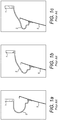
- Figure 1a shows a surround 1 having a reverse roll 3 which is connected to a diaphragm 5; in this drawing the surround 1 is shown at rest, in Figures 1b and 1c the diaphragm 5 has been displaced backwardly (i.e. to the left in the drawing).
- Figure 1b the surround is displaced in free air (i.e. there is no enclosure), whereas in Figure 1c the surround 1 is fixed to a relatively small (41) enclosure (not shown).
- the outer edge of the surround 1 (the thickest, uppermost part in the drawings) is fixed (in Figure 1c it would be fixed to the enclosure).
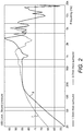
- the surrounds producing the frequency curves illustrated have the following characteristics: Thin surround 7 (0.7mm) Thick surround 9 (1.5mm) Resting stiffness 2400 N/m 14400 N/m Breakup frequency 1250 Hz 780 Hz Sensitivity 87dB 85dB Moving mass 18.5 20.5g Buckling 13mm >20mm
- FIG. 3 illustrates the change in restoring force for two similar surrounds, the first shown as curve 11 is of the surround moving in free air (as in Figure 1b ) and the second shown as curve 13 moving when fixed to a relatively small (4l) enclosure; it can be clearly seen that the surround has a much more linear restoring force range in the free air example.
- US 2006/110002 attempts to address these problems and discloses a loudspeaker suspension structure having an inner circumferential border, an outer circumferential border, and grooves each extending from the inner circumferential border to the outer circumferential border at an angle with respect to a normal to the inner circumferential border, a profile of a circumferential section of the suspension structure having continuous curvature.
- Each of the grooves varies from the inner border to the outer border, the variation corresponding to a variation of a principal contour of the suspension structure.
- the present invention is predicated on a realisation that providing the surround with a means to deform in a controlled manner can avoid previously uncontrolled geometric buckling whilst deforming ("unfolding") in a controlled manner and resisting back pressure, and that an appropriately shaped and configured surround can also help minimise the mass of the surround.
- the present invention therefore provides a loudspeaker driver surround comprising a generally annular element of flexible and suitably resilient material and having a central axis along which in use a diaphragm is driven, a first circumferential edge for fitment to an enclosure and a second circumferential edge for fitment to a diaphragm and/or a voice coil, with a roll surface extending between the edges which projects in the direction of the axis, the roll surface being provided with a plurality of smoothly rounded corrugations or folds extending generally radially with respect to the annular element between the outer and inner edges thereof, the corrugations being shaped and configured such that the roll surface is non-axisymmetric about the axis, and such that cross-sections of the roll surface which extend radially with respect to the annular element between the first and second edges thereof have a substantially constant length at all circumferential positions around the annular element and so that the shape of the said cross-section varies continuously between successive circumferential positions around the annular element, the corrugations
- corrugations is used herein to denote a rounded surface having a series of ridges and furrows which are smoothly contoured, with no sharp-edged grooves, folds, pleats or sharp discontinuities in surface shape; such smooth corrugations are able to unfold predictably, like sharply pleated corrugations, but they unfold over a more extensive area and are more resistant to back pressure.
- Another advantage is that at high excursions the sharp edges of a pleated surround will open more readily as the angle of the fold increases, resulting in a reduction of the restoring force. In contrast, with smooth corrugations this reduction in the restoring force would not happen, as the unfolding takes place over the whole surface of a smooth corrugation (rather than just at the sharp edges of a pleated surround).
- driver surrounds with a smoothly corrugated roll surface which is non-axisymmetric but which has a high order of rotational symmetry (of at least 30, 40 or 50, but up to any number such as 100 or 200, provided suitably accurate tooling can be produced to manufacture the surrounds) can avoid buckling under back pressure yet deform controllably in the region of the corrugations when the diaphragm is driven without adversely affecting audio performance.
- Having corrugations on essentially all parts of the roll surface i.e. all the parts of the surround which move in use) avoids axisymmetry.
- Axisymmetry means symmetric about the axis at any angle around that axis; an object has rotational symmetry if there is a centre point around which the object is turned (rotated) a certain number of degrees and the object looks the same.
- the number of positions in which the object looks exactly the same is called the order of symmetry; the order of symmetry is the same as the number of corrugations.
- the roll surface allows the roll surface to be of substantially constant thickness, which minimises the mass of the surround in the sense that the corrugations add no material which does not contribute to the ability of the surround to flex and the diaphragm to reciprocate along the drive axis (corrugated surrounds per se are not new, see for example US 8340340 which has corrugations which "bulge" at the top of the surround, but which do not add to the surround's ability to extend axially).
- the first circumferential edge is the outer edge and the second edge is the inner edge.
- each corrugation is neither wholly radial nor wholly non-radial; and, when we refer to the surround being viewed it is intended that the resiliently flexible surround is viewed in its relaxed state.
- points on others of the corrugations which points are most axially distant from the circumferential edges, form generally linear creases at a second angle to the radial direction between the circumferential edges (this also means that the second angle is neither 0° nor 90°).
- the first and second angles are preferably equal and opposite, and the linear creases may be joined at their ends.
- the roll surface preferably comprises a succession of curves alternating to the left and right hand side of a centre line, said curves blending into a uniform roll surface between each curve.
- the left and right hand side curves may be mirror images, similar but reversed, and are preferably aligned relative to the uniform roll section that there is no single common point of intersection of the three profiles; they may have a saw tooth profile, having steep and gentle slopes in alternating directions.
- Such an arrangement allows the roll surface to have a large effective thickness, whilst avoiding the geometric buckling which would be encouraged were there a common intersection point between all three profiles.
- the exact shape can be determined empirically, and is dependent on the process used to manufacture the surround.
- the shape and configuration of the corrugations on the roll surface are such that if one circumferential edge of the annular element were extended axially away from the other circumferential edge to the maximum extent, the roll surface would adopt a substantially smooth frusto-conical shape.
- This is a design constraint which helps minimise the amount of material in the surround whilst still allowing it to deform controllably and without adverse effects on the sound quality.
- Another feature which affects the weight of the surround is its thickness; the present design is such that the thickness is able to be substantially constant, and this is preferred.
- corrugations may extend along these and blend smoothly to disappear at the circular junctures between the sidewalls and the outer and inner edges.
- the corrugations blend into each other smoothly and with no sudden discontinuities.
- the invention also encompasses a loudspeaker having a driver surround as defined above.
- Figure 4 shows an annular loudspeaker suspension 2 in its relaxed state (as is the case in all of the subsequent drawings) which has a flat outer circumferential edge 6 for mounting or clamping to the loudspeaker enclosure (not shown) and a flat inner circumferential edge 4 which is configured to be attached to the diaphragm (not shown) or to the voice coil (not shown) of the loudspeaker.
- the inner and outer edges 4, 6 are in approximately the same plane.
- the voice coil and the diaphragm vibrate at audio frequencies in the direction of the central axis 8 of the annular surround 2, and the outer edge 6 remains fixed whilst the inner edge 4 reciprocates along axis 8 relative to the outer edge 6 and the loudspeaker enclosure.
- the suspension 2 is unitary (i.e. formed in one piece) and is formed of a suitably resilient material (such as by being moulded of an elastic material, as is known in the art), and serves to hold the diaphragm/voice coil aligned on the axis 8 throughout the reciprocal motion, and also to urge the diaphragm/voice coil towards a central position where the surround is in its relaxed state, e.g. so that the two edges sit in approximately the same plane along axis 8, counteracting the drive forces produced by the voice coil.
- the surround described has all the attributes of known loudspeaker surrounds, and is as described above in relation to the prior art.
- the surround 2 is very generally in the form of a part of a torus, in that it protrudes in the direction of axis 8 away from the general plane of the inner and outer edges 4, 6; however, the protruding portion of the surround (the 'roll surface') is formed with a plurality of corrugations 10 which give it a complex, non-axisymmetric shape, particularly when viewed along the direction of the axis 8.
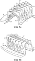
- the roll surface has inner and outer sidewalls 18, 20 (shown in Figure 5a ) which extend generally axially and which are generally cylindrical, and these are connected to the inner and outer edges at a crease 16.
- the corrugations 10 extend along a part of the sidewalls 18 and blend smoothly into the sidewalls at or before reaching the crease 16.
- the important features of the shape of the corrugated surface of the surround 2 between the outer and inner edges 4, 6 are, firstly, that it is not axisymmetric about axis 8 (meaning that if successive radial cross-sections are taken at different positions around axis 8, the shape of those cross-sections does not remain constant (it will be noted from Figures 5a and 5b that the corrugations 10 blend smoothly into outer and inner sidewalls 18, 20 which are either cylindrical or frusto conical and extend along the axis 8; sidewalls are not an essential feature of the invention, but where they are present the corrugations 10 must continue onto the sidewall to prevent it from buckling, and could blend smoothly into the crease 16 where the surround turns to form the flat inner and outer edges, as shown in Figure 5a ).
- the corrugations 10 are shaped repetitively and substantially similarly; this gives the projecting roll surface an order of rotational symmetry of at least 30 and, subject to manufacturing constraints, up to 100 or even 200 or any number between these extremes; such a high number of corrugations makes the surround effective in resisting back pressure within the loudspeaker enclosure, whilst they each form the leaves of a 'hinge' that opens or unfolds to allow the driver to move while resisting the pressure from the change in volume of the enclosure.
- the arrangement is such that there is no part of the roll surface which does not have corrugations.
- the corrugations are shaped such that, if radial cross-sections of the roll surface are taken at different angular positions around the axis 8, the length of the roll surface in a radial direction between the edges 4, 6 remains constant.
- the corrugations are at alternate and substantially equal angles to the radial direction in a zigzag pattern, as is best seen in Figure 7 .
- the radial profile of the roll surface varies between a half roll shape and a sharp cornered saw tooth shape (with alternate steep and gentle slopes, as seen in Figures 5 , 6 and 10b ) so as to give a large change in axial position for points on the roll surface at successive circumferential positions.
- this leading surface L is generally annular about the axis 8, but is not planar (although in the drawings it might appear so, it can be seen in Figures 6a and 6b that the leading surface L' is not planar, but instead is very slightly convex - this is described further below, with reference to Figure 10 ).
- the overall shape of the roll surface permits the roll surface to "unfold" without buckling as the surround vibrates in use, to the extent that, were the inner edge 6 to be displaced along the axis 8 relative to the outer edge 4 to the maximum extent possible, the roll surface would unroll completely to form a substantially smooth, frusto-conical shape, but without any buckling and without any rotation of the inner edge 6 relative to the outer edge 4; this minimises the mass of the surround for the maximum excursion of the central diaphragm, and allows the restoring force of the surround (the resilience of the material from which it is formed which moves the surround from a driven opposition towards the relaxed position) to be substantially linearised.
- Figures 5a and 5b are enlarged views of part of the surround 2 shown in Figure 4
- Figure 7 is a plan view of that surround, as seen along the axis 8.
- the rounded corrugations axially furthest from the edges 2,4 form a symmetrical zigzag shape which has portions 12, 14 (also shown in Figure 7 ) which alternate at similar but opposite angles to the radial direction, and which terminate at rounded "knees", or "shoulders", 36, 38 (see Figure 10b ) pointing alternately inwards and outwards; these corrugations allow the surround to deform without any rotational movement of the inner edge 6 relative to the outer edge 4.
- the shoulders 36, 38 lie along two circumferential rings, one towards the inner edge of the annular surround and the other towards its outer edge.
- the angle of the corrugations to the radial direction is dependent on the size and number of corrugations; in a surround having 50 corrugations, each corrugation subtends about 7.2° and successive portions 12, 14 are angled at about 15° to the radial direction.
- FIGs 6a and 6b show two sections of an alternative form of surround 2' in which features similar in function but not necessarily shape or configuration to those in the surround 2 of Figure 4 are given the same reference numeral as in Figure 4 but with the addition of a dash.
- the corrugations 10 clearly extend along the inner and outer axial sidewalls 18', 20' of the roll surface towards the crease 16'.
- the corrugations 10, 10' are preferably smooth, as this facilitates manufacture of the surround (smoothly curved shapes are easily moulded, where sharp corners would make the mould more expensive, and/or make it more complicated and the surround liable to 'stick' in the mould).
- the inner circumferential edge 4' is shown at a slight angle to the plane of outer edge 6' (in the direction of the leading surface) so as to be suitable to have a conical or domed diaphragm attached thereto.
- Figures 8a and 8b illustrate the principles for determining the number of corrugations which should be used.
- the number of points of the star is mainly determined by the ratio of the inside clamp diameter at the cone and the outside clamp diameter at the surround foot. From measurements of surrounds of various sizes in free air, it has been found that the angle the folds make with a radius (fold angle) is between 30° and 50° (rounded for an integer number of repetitions per 360°). Adding corrugations gives the surround points at which to "fold" into a smaller diameter, thus eliminating the abrupt geometric buckling.
- the number of corrugations must be at least the number of geometric buckling points with a 50° fold angle, and preferably several times more.
- Figures 8a and 8b show how the number of geometric buckling points is determined on a simple half roll surround with a 1: 1.175 ratio of inside: outside diameter.
- Figure 8a relates to the maximum fold angle and gives the minimum number of geometric buckling points; 15 folds spaced 24° apart, give a fold angle 22 of 47° (predicted minimum number of geometric buckling points), therefore a minimum of 15 corrugations would be required to eliminate geometric buckling.
- the exact number of corrugations required to resist the pressure deformation should be greater than the maximum predicted number of geometric buckling points for the surround; this number depends on the surround width, material thickness, and change in cabinet volume, but is typically of the order of 30 or higher.
- outer diameter is typically around 1: 1.3, which would give a minimum of 17 folds, and for very large surrounds, of inner: outer diameter as large as 1: 1.45, there would be a minimum of 13 folds, and for such surrounds about 30 corrugations would be suitable.
- Figure 9 illustrates how the radial cross-sectional shape of the roll surface should be chosen.
- the change in shape of the surround profile should be large. Varying between a half roll profile and saw teeth profiles of alternating directions gives a large change in position for each point along the surround length, and so increases the effective thickness.
- the effective thickness is defined as the area of the difference between the middle and extreme profiles divided by the length of the roll.
- Figure 9 shows a comparison of the shape, viewed in radial cross-section, where the alternating saw tooth pattern varies between a half roll shape 26 and an alternating parabolic shape 28, and between a half roll shape 26 and a sharp saw tooth shape 30.
- Both the alternating parabolic shape 28 and the sharp saw tooth shape 30 are of equal length to the half roll 26, which is 20mm in diameter.
- the effective thickness is the total area formed by the difference between the extreme surround profiles divided by the length. As can be seen, the effective thickness of the sharp saw tooth 30 is more than twice the parabolic shape 28, so it will be better at resisting pressure deformation.
- the effective thickness ratio is the effective thickness divided by the material thickness of the surround. For a surround 0.7mm thick, this would give an effective thickness ratio of 1.709 for the parabolic profile, and 3.809 for the saw tooth profile.
- Figure 10 shows two surrounds of the same length with different corrugation profiles.
- the centre point 32 is common to all three profiles (the left hand extreme, the half roll and the right hand extreme) so forms a thin circular ring of material that is prone to geometric buckling.
- the surround in Figure 10b has no common points between all three profiles, only two spaced points 32" where there are common points between two profiles, so this surround is much less liable to buckle geometrically but instead it unfolds at the corrugations, and also has a greater effective thickness.
- the left and right hand peaks, or "shoulders" 36, 38 are at the same height above the line 34 (i.e.
- any use in this description or in the claims of the terms “annular”, “circumference”, “circumferential”, “circumferentially” or “around” should not be construed as being restricted to a circular shape, nor as necessarily being centred on a single axis but instead construed broadly as any substantially two-dimensional shape bounded by a closed loop.
- the invention has been described above in terms of the outer edge of the annular suspension being fixed and the inner edge moving relative thereto, as this is the arrangement in the majority of loudspeakers; however, it will be appreciated that the reverse arrangement (inner edge fixed, outer edge moving) could work equally as well, and so falls within the ambit of this invention.
- the roll surface can be directed in either axial direction from the outer edges (i.e. a roll or a reverse roll).
- the corrugations have been described as having a zigzag pattern, of equal and opposite angles which alternate in direction; the zigzag pattern could alternatively be sinusoidal, or in any other repeating waveform. Where different variations or alternative arrangements are described above, it should be understood that embodiments of the invention may incorporate such variations and/or alternatives in any suitable combination.
Landscapes
- Engineering & Computer Science (AREA)
- Physics & Mathematics (AREA)
- Acoustics & Sound (AREA)
- Signal Processing (AREA)
- Multimedia (AREA)
- Diaphragms For Electromechanical Transducers (AREA)
Claims (16)
- Lautsprechertreiberumgebung, umfassend ein im Allgemeinen ringförmiges Element (2) aus elastischem Material und eine mittlere Achse (8) aufweisend, entlang der bei Verwendung eine Membran angetrieben wird, eine erste umlaufende Kante (6) zur Befestigung an einem Gehäuse und eine zweite umlaufende Kante (4) zur Befestigung an der Membran und/oder einer Sprechspule, mit einer sich zwischen den Kanten (4, 6) erstreckenden Wulstoberfläche, die in Richtung der Achse (8) herausragt, wobei die Wulstoberfläche eine Form hat, die durch mehrere axiale Wellen (10), die sich im Allgemeinen radial bezüglich des ringförmigen Elements (2) zwischen der ersten und zweiten Kante (4, 6) davon erstrecken, gebildet wird, wobei die Wellen (10) so geformt und ausgelegt sind, dass die Wulstoberfläche nicht axialsymmetrisch um die Achse (8) ist, und so, dass Querschnitte der Wulstoberfläche, die sich radial bezüglich des ringförmigen Elements (2) zwischen der ersten und zweiten Kante (4, 6) davon erstrecken, eine im Wesentlichen konstante Länge bei allen umlaufenden Positionen rund um das ringförmige Element (2) aufweisen, und so, dass die Form der Querschnitte kontinuierlich zwischen umlaufenden Positionen rund um das ringförmige Element (2) variiert, wobei die Wellen (10) der herausragenden Wulstoberfläche eine Rotationssymmetrie einer Ordnung von mindestens 30 verleihen.
- Lautsprechertreiberumgebung nach Anspruch 1, wobei (wenn das ringförmige Element (2) axial gesehen wird) Punkte auf einigen der Wellen (10), wobei Punkte am weitesten axial entfernt von den umlaufenden Kanten (4, 6) sind, allgemein lineare Falten (12) mit einem ersten Winkel zur radialen Richtung zwischen den äußeren und inneren Kanten (6, 4) bilden.
- Lautsprechertreiberumgebung nach Anspruch 2, wobei (wenn das ringförmige Element axial gesehen wird) Punkte auf anderen der Wellen (10), wobei Punkte am weitesten axial entfernt von den umlaufenden Kanten (4, 6) sind, allgemein lineare Falten (140) mit einem zweiten Winkel zur radialen Richtung zwischen den äußeren und inneren Kanten (6, 4) bilden.
- Lautsprechertreiberumgebung nach Anspruch 3, wobei der erste und der zweite Winkel gleich und einander entgegengesetzt sind.
- Lautsprechertreiberumgebung nach Anspruch 3, wobei im radialen Querschnitt die Wulstoberfläche eine Folge von Kurven umfasst, die zur linken und rechten Seite einer mittleren Linie (32) alternieren, wobei die Kurven in eine gleichförmige Wulstoberfläche zwischen den einzelnen Kurven zusammenlaufen.
- Lautsprechertreiberumgebung nach Anspruch 5, wobei die Kurven auf der linken und rechten Seite ähnlich, aber umgekehrt sind.
- Lautsprechertreiberumgebung nach Anspruch 5 oder Anspruch 6, wobei die gleichförmige Wulstoberfläche eine Halbrundoberfläche ist.
- Lautsprechertreiberumgebung nach einem der Ansprüche 3 bis 7, wobei, wenn die Teile (36, 38, 40) der Wellen (10), die axial am weitesten von den umlaufenden Kanten (4, 6) entfernt sind, bei unterschiedlichen Radien verwendet werden, um eine führende Oberfläche zu erzeugen, die führende Oberfläche nicht planar wäre.
- Lautsprechertreiberumgebung nach einem der vorhergehenden Ansprüche, wobei die Form und Auslegung der Wellen (10) auf der Wulstoberfläche so sind, dass, wenn sich die erste Kante (6) des ringförmigen Elements (2) axial von der zweiten Kante (4) bis zum maximal möglichen Ausmaß weg erstrecken würde, die Wulstoberfläche und die Wellen (10) davon sich glätten würden, um eine im wesentlichen glatte kegelstumpfförmige Form anzunehmen.
- Lautsprechertreiberumgebung nach einem der vorhergehenden Ansprüche, wobei die Wulstoberfläche eine Seitenwand (20) angrenzend an die erste Kante (6) hat, die sich im Wesentlichen axial erstreckt.
- Lautsprechertreiberumgebung nach einem der vorhergehenden Ansprüche, wobei die Wulstoberfläche eine Seitenwand (18) angrenzend an die zweite Kante (4) hat, die sich im Wesentlichen axial erstreckt.
- Lautsprechertreiberumgebung nach einem der vorhergehenden Ansprüche, wobei aufeinander folgende Wellen (10) gleichmäßig ineinander zusammenlaufen.
- Lautsprechertreiberumgebung nach einem der vorhergehenden Ansprüche, wobei die Wellen (10) gleichmäßig in die erste und/oder die zweite Kante (6, 4) hineinlaufen.
- Lautsprechertreiberumgebung nach einem der vorhergehenden Ansprüche, wobei die Dicke der Wulstoberfläche im Wesentlichen konstant ist.
- Lautsprechertreiberumgebung nach einem der vorhergehenden Ansprüche, wobei die erste umlaufende Kante (6) die innere Kante der im Allgemeinen ringförmigen Umgebung (2) ist und die zweite Kante (4) die äußere Kante der Umgebung (2) ist.
- Lautsprecher, umfassend eine Lautsprechertreiberumgebung nach einem der vorhergehenden Ansprüche.
Applications Claiming Priority (1)
| Application Number | Priority Date | Filing Date | Title |
|---|---|---|---|
| GB1702849.9A GB2560496B (en) | 2017-03-16 | 2017-03-16 | Loudspeaker driver surround |
Publications (2)
| Publication Number | Publication Date |
|---|---|
| EP3367699A1 EP3367699A1 (de) | 2018-08-29 |
| EP3367699B1 true EP3367699B1 (de) | 2020-07-08 |
Family
ID=58486846
Family Applications (1)
| Application Number | Title | Priority Date | Filing Date |
|---|---|---|---|
| EP18275027.3A Active EP3367699B1 (de) | 2017-03-16 | 2018-02-20 | Lautsprecher fahrer surround |
Country Status (4)
| Country | Link |
|---|---|
| US (1) | US10771901B2 (de) |
| EP (1) | EP3367699B1 (de) |
| CN (1) | CN108632722B (de) |
| GB (1) | GB2560496B (de) |
Families Citing this family (5)
| Publication number | Priority date | Publication date | Assignee | Title |
|---|---|---|---|---|
| FR3035295B1 (fr) * | 2015-04-15 | 2017-04-21 | Focal Jmlab | Dispositif de suspension pour haut-parleur, procede de fabrication et haut-parleur associes |
| EP3723387A1 (de) * | 2019-04-11 | 2020-10-14 | Purifi ApS | Lautsprecher mit einer ungleichmässigen aufhängung und einem verstärkungselement |
| CN112804623B (zh) * | 2019-11-13 | 2022-09-02 | 华为技术有限公司 | 扬声器及电子设备 |
| FR3125667B1 (fr) * | 2021-07-21 | 2024-04-12 | Cabasse | Suspension nervurée, haut-parleur et enceinte acoustique la comportant |
| EP4356625A1 (de) * | 2021-07-21 | 2024-04-24 | Cabasse | Gerippte aufhängung, lautsprecher und akustische kammer damit |
Family Cites Families (22)
| Publication number | Priority date | Publication date | Assignee | Title |
|---|---|---|---|---|
| NL34823C (de) * | 1930-07-29 | |||
| GB368926A (en) * | 1931-01-29 | 1932-03-17 | Victor Talking Machine Co | Improvements in acoustic diaphragms |
| US2442791A (en) * | 1945-09-07 | 1948-06-08 | Bell Telephone Labor Inc | Acoustic device |
| US3563337A (en) * | 1968-03-06 | 1971-02-16 | Hitachi Ltd | Electroacoustic transducer |
| JPS5567297A (en) * | 1978-11-14 | 1980-05-21 | Lansing Sound | Suspending device for acoustic diaphragm |
| US4324312A (en) * | 1978-11-14 | 1982-04-13 | James B. Lansing Sound, Inc. | Diaphragm suspension construction |
| JPS58127499A (ja) * | 1982-01-25 | 1983-07-29 | Matsushita Electric Ind Co Ltd | スピ−カの振動系支持装置 |
| EP0919107A1 (de) | 1996-08-12 | 1999-06-02 | CARVER, Robert Weir | Tiefbasslautsprecher mit hoher gegendruck-emk |
| US6851513B2 (en) * | 2001-03-27 | 2005-02-08 | Harvard International Industries, Incorporated | Tangential stress reduction system in a loudspeaker suspension |
| EP1413170A2 (de) * | 2001-07-19 | 2004-04-28 | Koninklijke Philips Electronics N.V. | Elektroakusticher wandler mit einer membran mit einem verbesserten faltenbereich |
| CA2407123C (en) * | 2001-10-16 | 2007-12-18 | Audio Products International Corp. | Low distortion loudspeaker cone suspension |
| US7054459B2 (en) * | 2002-05-17 | 2006-05-30 | Matsushita Electric Industrial Co., Ltd. | Surrounding structure of a loudspeaker |
| AU2003272919A1 (en) * | 2002-10-25 | 2004-05-13 | Matsushita Electric Industrial Co., Ltd. | Suspension and electro-acoustic transducer using the suspension |
| US8139812B2 (en) * | 2004-11-19 | 2012-03-20 | Subarna Basnet | Loudspeaker suspension |
| US7397927B2 (en) * | 2004-11-19 | 2008-07-08 | Bose Corporation | Loudspeaker suspension |
| CN201403189Y (zh) * | 2009-04-17 | 2010-02-10 | 天津市中环电子信息集团有限公司 | 一种超薄型扬声器复合盆 |
| GB2471884A (en) * | 2009-07-17 | 2011-01-19 | Gp Acoustics | Loudspeaker driver surround with at least one stiffening tab |
| US8340340B2 (en) * | 2010-01-07 | 2012-12-25 | Paradigm Electronics Inc. | Loudspeaker driver suspension |
| US9253576B2 (en) * | 2013-11-21 | 2016-02-02 | Bose Corporation | Suspension for acoustic device |
| CN109905816B (zh) * | 2014-01-22 | 2021-01-26 | 宁波升亚电子有限公司 | 一种无弹波扬声器及其制造方法 |
| CN104918201A (zh) * | 2015-04-14 | 2015-09-16 | 歌尔声学股份有限公司 | 一种再加工振膜的方法、振膜以及受话器 |
| CN205726369U (zh) * | 2016-06-20 | 2016-11-23 | 杨安足 | 一种有效减少分割振动的纸盆 |
-
2017
- 2017-03-16 GB GB1702849.9A patent/GB2560496B/en active Active
-
2018
- 2018-02-20 EP EP18275027.3A patent/EP3367699B1/de active Active
- 2018-02-22 US US15/902,634 patent/US10771901B2/en active Active
- 2018-02-22 CN CN201810153881.9A patent/CN108632722B/zh active Active
Non-Patent Citations (1)
| Title |
|---|
| None * |
Also Published As
| Publication number | Publication date |
|---|---|
| GB2560496B (en) | 2021-09-29 |
| US10771901B2 (en) | 2020-09-08 |
| CN108632722A (zh) | 2018-10-09 |
| GB2560496A (en) | 2018-09-19 |
| US20180242086A1 (en) | 2018-08-23 |
| CN108632722B (zh) | 2021-02-02 |
| GB201702849D0 (en) | 2017-04-05 |
| EP3367699A1 (de) | 2018-08-29 |
Similar Documents
| Publication | Publication Date | Title |
|---|---|---|
| EP3367699B1 (de) | Lautsprecher fahrer surround | |
| US6851513B2 (en) | Tangential stress reduction system in a loudspeaker suspension | |
| EP2952014B1 (de) | Elektroakustische membran | |
| US8340340B2 (en) | Loudspeaker driver suspension | |
| CN101002502B (zh) | 用于具有可动线圈的扬声器的振膜 | |
| JP5020503B2 (ja) | ラウドスピーカの懸架装置 | |
| US20190069093A1 (en) | Audio Speaker Surround Geometry For Improved Pistonic Motion | |
| CN106537935B (zh) | 发声系统 | |
| EP2869595B1 (de) | Elektroakustikwandler | |
| US6863153B1 (en) | Loudspeaker diaphragm | |
| TWI835518B (zh) | 一種揚聲器 | |
| AU2008359684A1 (en) | Nested compound loudspeaker drive unit | |
| CN1833465A (zh) | 浅扬声器 | |
| HK1254523A1 (en) | Loudspeaker driver surround | |
| KR19990044918A (ko) | 방사상으로 활모양인 고주파 중심 스피커 원뿔체 | |
| CN110199527B (zh) | 扬声器 | |
| EP1833279B1 (de) | Gekoppeltes Gehäuse einer Lautsprechervorrichtung | |
| CN108810755A (zh) | 膜片组件、传感器及制造方法 | |
| JPH11313391A (ja) | スピーカ用振動板のエッジ | |
| CN221283343U (zh) | 一种振膜及扬声器 | |
| CN113841424B (zh) | 具有不均匀悬架和加强元件的扩音器 | |
| CN105872893A (zh) | 嵌套式复合扬声器驱动单元 | |
| WO2019125673A1 (en) | Acoustic transducer with pivoted surround | |
| JPH077789A (ja) | コーン型スピーカ | |
| JP2025084113A (ja) | ラウドスピーカーボイスコイルボビン |
Legal Events
| Date | Code | Title | Description |
|---|---|---|---|
| PUAI | Public reference made under article 153(3) epc to a published international application that has entered the european phase |
Free format text: ORIGINAL CODE: 0009012 |
|
| STAA | Information on the status of an ep patent application or granted ep patent |
Free format text: STATUS: THE APPLICATION HAS BEEN PUBLISHED |
|
| AK | Designated contracting states |
Kind code of ref document: A1 Designated state(s): AL AT BE BG CH CY CZ DE DK EE ES FI FR GB GR HR HU IE IS IT LI LT LU LV MC MK MT NL NO PL PT RO RS SE SI SK SM TR |
|
| AX | Request for extension of the european patent |
Extension state: BA ME |
|
| STAA | Information on the status of an ep patent application or granted ep patent |
Free format text: STATUS: REQUEST FOR EXAMINATION WAS MADE |
|
| 17P | Request for examination filed |
Effective date: 20180927 |
|
| RBV | Designated contracting states (corrected) |
Designated state(s): AL AT BE BG CH CY CZ DE DK EE ES FI FR GB GR HR HU IE IS IT LI LT LU LV MC MK MT NL NO PL PT RO RS SE SI SK SM TR |
|
| GRAP | Despatch of communication of intention to grant a patent |
Free format text: ORIGINAL CODE: EPIDOSNIGR1 |
|
| STAA | Information on the status of an ep patent application or granted ep patent |
Free format text: STATUS: GRANT OF PATENT IS INTENDED |
|
| INTG | Intention to grant announced |
Effective date: 20200210 |
|
| GRAS | Grant fee paid |
Free format text: ORIGINAL CODE: EPIDOSNIGR3 |
|
| GRAA | (expected) grant |
Free format text: ORIGINAL CODE: 0009210 |
|
| STAA | Information on the status of an ep patent application or granted ep patent |
Free format text: STATUS: THE PATENT HAS BEEN GRANTED |
|
| AK | Designated contracting states |
Kind code of ref document: B1 Designated state(s): AL AT BE BG CH CY CZ DE DK EE ES FI FR GB GR HR HU IE IS IT LI LT LU LV MC MK MT NL NO PL PT RO RS SE SI SK SM TR |
|
| REG | Reference to a national code |
Ref country code: AT Ref legal event code: REF Ref document number: 1289782 Country of ref document: AT Kind code of ref document: T Effective date: 20200715 Ref country code: CH Ref legal event code: EP |
|
| REG | Reference to a national code |
Ref country code: DE Ref legal event code: R096 Ref document number: 602018005908 Country of ref document: DE |
|
| REG | Reference to a national code |
Ref country code: IE Ref legal event code: FG4D |
|
| REG | Reference to a national code |
Ref country code: LT Ref legal event code: MG4D |
|
| REG | Reference to a national code |
Ref country code: AT Ref legal event code: MK05 Ref document number: 1289782 Country of ref document: AT Kind code of ref document: T Effective date: 20200708 |
|
| REG | Reference to a national code |
Ref country code: NL Ref legal event code: MP Effective date: 20200708 |
|
| PG25 | Lapsed in a contracting state [announced via postgrant information from national office to epo] |
Ref country code: LT Free format text: LAPSE BECAUSE OF FAILURE TO SUBMIT A TRANSLATION OF THE DESCRIPTION OR TO PAY THE FEE WITHIN THE PRESCRIBED TIME-LIMIT Effective date: 20200708 Ref country code: PT Free format text: LAPSE BECAUSE OF FAILURE TO SUBMIT A TRANSLATION OF THE DESCRIPTION OR TO PAY THE FEE WITHIN THE PRESCRIBED TIME-LIMIT Effective date: 20201109 Ref country code: HR Free format text: LAPSE BECAUSE OF FAILURE TO SUBMIT A TRANSLATION OF THE DESCRIPTION OR TO PAY THE FEE WITHIN THE PRESCRIBED TIME-LIMIT Effective date: 20200708 Ref country code: FI Free format text: LAPSE BECAUSE OF FAILURE TO SUBMIT A TRANSLATION OF THE DESCRIPTION OR TO PAY THE FEE WITHIN THE PRESCRIBED TIME-LIMIT Effective date: 20200708 Ref country code: GR Free format text: LAPSE BECAUSE OF FAILURE TO SUBMIT A TRANSLATION OF THE DESCRIPTION OR TO PAY THE FEE WITHIN THE PRESCRIBED TIME-LIMIT Effective date: 20201009 Ref country code: NO Free format text: LAPSE BECAUSE OF FAILURE TO SUBMIT A TRANSLATION OF THE DESCRIPTION OR TO PAY THE FEE WITHIN THE PRESCRIBED TIME-LIMIT Effective date: 20201008 Ref country code: AT Free format text: LAPSE BECAUSE OF FAILURE TO SUBMIT A TRANSLATION OF THE DESCRIPTION OR TO PAY THE FEE WITHIN THE PRESCRIBED TIME-LIMIT Effective date: 20200708 Ref country code: BG Free format text: LAPSE BECAUSE OF FAILURE TO SUBMIT A TRANSLATION OF THE DESCRIPTION OR TO PAY THE FEE WITHIN THE PRESCRIBED TIME-LIMIT Effective date: 20201008 Ref country code: SE Free format text: LAPSE BECAUSE OF FAILURE TO SUBMIT A TRANSLATION OF THE DESCRIPTION OR TO PAY THE FEE WITHIN THE PRESCRIBED TIME-LIMIT Effective date: 20200708 Ref country code: ES Free format text: LAPSE BECAUSE OF FAILURE TO SUBMIT A TRANSLATION OF THE DESCRIPTION OR TO PAY THE FEE WITHIN THE PRESCRIBED TIME-LIMIT Effective date: 20200708 |
|
| PG25 | Lapsed in a contracting state [announced via postgrant information from national office to epo] |
Ref country code: IS Free format text: LAPSE BECAUSE OF FAILURE TO SUBMIT A TRANSLATION OF THE DESCRIPTION OR TO PAY THE FEE WITHIN THE PRESCRIBED TIME-LIMIT Effective date: 20201108 Ref country code: RS Free format text: LAPSE BECAUSE OF FAILURE TO SUBMIT A TRANSLATION OF THE DESCRIPTION OR TO PAY THE FEE WITHIN THE PRESCRIBED TIME-LIMIT Effective date: 20200708 Ref country code: PL Free format text: LAPSE BECAUSE OF FAILURE TO SUBMIT A TRANSLATION OF THE DESCRIPTION OR TO PAY THE FEE WITHIN THE PRESCRIBED TIME-LIMIT Effective date: 20200708 Ref country code: LV Free format text: LAPSE BECAUSE OF FAILURE TO SUBMIT A TRANSLATION OF THE DESCRIPTION OR TO PAY THE FEE WITHIN THE PRESCRIBED TIME-LIMIT Effective date: 20200708 |
|
| PG25 | Lapsed in a contracting state [announced via postgrant information from national office to epo] |
Ref country code: NL Free format text: LAPSE BECAUSE OF FAILURE TO SUBMIT A TRANSLATION OF THE DESCRIPTION OR TO PAY THE FEE WITHIN THE PRESCRIBED TIME-LIMIT Effective date: 20200708 |
|
| REG | Reference to a national code |
Ref country code: DE Ref legal event code: R097 Ref document number: 602018005908 Country of ref document: DE |
|
| PG25 | Lapsed in a contracting state [announced via postgrant information from national office to epo] |
Ref country code: RO Free format text: LAPSE BECAUSE OF FAILURE TO SUBMIT A TRANSLATION OF THE DESCRIPTION OR TO PAY THE FEE WITHIN THE PRESCRIBED TIME-LIMIT Effective date: 20200708 Ref country code: DK Free format text: LAPSE BECAUSE OF FAILURE TO SUBMIT A TRANSLATION OF THE DESCRIPTION OR TO PAY THE FEE WITHIN THE PRESCRIBED TIME-LIMIT Effective date: 20200708 Ref country code: CZ Free format text: LAPSE BECAUSE OF FAILURE TO SUBMIT A TRANSLATION OF THE DESCRIPTION OR TO PAY THE FEE WITHIN THE PRESCRIBED TIME-LIMIT Effective date: 20200708 Ref country code: EE Free format text: LAPSE BECAUSE OF FAILURE TO SUBMIT A TRANSLATION OF THE DESCRIPTION OR TO PAY THE FEE WITHIN THE PRESCRIBED TIME-LIMIT Effective date: 20200708 Ref country code: SM Free format text: LAPSE BECAUSE OF FAILURE TO SUBMIT A TRANSLATION OF THE DESCRIPTION OR TO PAY THE FEE WITHIN THE PRESCRIBED TIME-LIMIT Effective date: 20200708 Ref country code: IT Free format text: LAPSE BECAUSE OF FAILURE TO SUBMIT A TRANSLATION OF THE DESCRIPTION OR TO PAY THE FEE WITHIN THE PRESCRIBED TIME-LIMIT Effective date: 20200708 |
|
| PLBE | No opposition filed within time limit |
Free format text: ORIGINAL CODE: 0009261 |
|
| STAA | Information on the status of an ep patent application or granted ep patent |
Free format text: STATUS: NO OPPOSITION FILED WITHIN TIME LIMIT |
|
| PG25 | Lapsed in a contracting state [announced via postgrant information from national office to epo] |
Ref country code: AL Free format text: LAPSE BECAUSE OF FAILURE TO SUBMIT A TRANSLATION OF THE DESCRIPTION OR TO PAY THE FEE WITHIN THE PRESCRIBED TIME-LIMIT Effective date: 20200708 |
|
| 26N | No opposition filed |
Effective date: 20210409 |
|
| PG25 | Lapsed in a contracting state [announced via postgrant information from national office to epo] |
Ref country code: SK Free format text: LAPSE BECAUSE OF FAILURE TO SUBMIT A TRANSLATION OF THE DESCRIPTION OR TO PAY THE FEE WITHIN THE PRESCRIBED TIME-LIMIT Effective date: 20200708 |
|
| PG25 | Lapsed in a contracting state [announced via postgrant information from national office to epo] |
Ref country code: SI Free format text: LAPSE BECAUSE OF FAILURE TO SUBMIT A TRANSLATION OF THE DESCRIPTION OR TO PAY THE FEE WITHIN THE PRESCRIBED TIME-LIMIT Effective date: 20200708 |
|
| PG25 | Lapsed in a contracting state [announced via postgrant information from national office to epo] |
Ref country code: MC Free format text: LAPSE BECAUSE OF FAILURE TO SUBMIT A TRANSLATION OF THE DESCRIPTION OR TO PAY THE FEE WITHIN THE PRESCRIBED TIME-LIMIT Effective date: 20200708 |
|
| REG | Reference to a national code |
Ref country code: BE Ref legal event code: MM Effective date: 20210228 |
|
| PG25 | Lapsed in a contracting state [announced via postgrant information from national office to epo] |
Ref country code: CH Free format text: LAPSE BECAUSE OF NON-PAYMENT OF DUE FEES Effective date: 20210228 Ref country code: LU Free format text: LAPSE BECAUSE OF NON-PAYMENT OF DUE FEES Effective date: 20210220 Ref country code: LI Free format text: LAPSE BECAUSE OF NON-PAYMENT OF DUE FEES Effective date: 20210228 |
|
| PG25 | Lapsed in a contracting state [announced via postgrant information from national office to epo] |
Ref country code: IE Free format text: LAPSE BECAUSE OF NON-PAYMENT OF DUE FEES Effective date: 20210220 |
|
| PG25 | Lapsed in a contracting state [announced via postgrant information from national office to epo] |
Ref country code: BE Free format text: LAPSE BECAUSE OF NON-PAYMENT OF DUE FEES Effective date: 20210228 |
|
| PG25 | Lapsed in a contracting state [announced via postgrant information from national office to epo] |
Ref country code: CY Free format text: LAPSE BECAUSE OF FAILURE TO SUBMIT A TRANSLATION OF THE DESCRIPTION OR TO PAY THE FEE WITHIN THE PRESCRIBED TIME-LIMIT Effective date: 20200708 |
|
| PG25 | Lapsed in a contracting state [announced via postgrant information from national office to epo] |
Ref country code: HU Free format text: LAPSE BECAUSE OF FAILURE TO SUBMIT A TRANSLATION OF THE DESCRIPTION OR TO PAY THE FEE WITHIN THE PRESCRIBED TIME-LIMIT; INVALID AB INITIO Effective date: 20180220 |
|
| PG25 | Lapsed in a contracting state [announced via postgrant information from national office to epo] |
Ref country code: MK Free format text: LAPSE BECAUSE OF FAILURE TO SUBMIT A TRANSLATION OF THE DESCRIPTION OR TO PAY THE FEE WITHIN THE PRESCRIBED TIME-LIMIT Effective date: 20200708 |
|
| PG25 | Lapsed in a contracting state [announced via postgrant information from national office to epo] |
Ref country code: MT Free format text: LAPSE BECAUSE OF FAILURE TO SUBMIT A TRANSLATION OF THE DESCRIPTION OR TO PAY THE FEE WITHIN THE PRESCRIBED TIME-LIMIT Effective date: 20200708 |
|
| PG25 | Lapsed in a contracting state [announced via postgrant information from national office to epo] |
Ref country code: TR Free format text: LAPSE BECAUSE OF FAILURE TO SUBMIT A TRANSLATION OF THE DESCRIPTION OR TO PAY THE FEE WITHIN THE PRESCRIBED TIME-LIMIT Effective date: 20200708 |
|
| PGFP | Annual fee paid to national office [announced via postgrant information from national office to epo] |
Ref country code: GB Payment date: 20251211 Year of fee payment: 9 |
|
| PGFP | Annual fee paid to national office [announced via postgrant information from national office to epo] |
Ref country code: FR Payment date: 20251219 Year of fee payment: 9 |
|
| PGFP | Annual fee paid to national office [announced via postgrant information from national office to epo] |
Ref country code: DE Payment date: 20251219 Year of fee payment: 9 |