EP3371407B1 - Klemmschutzschaltungsvorrichtung für eine vorrichtung zur automatischen bewegung von schiebefenstern bei einem kraftfahrzeug und entsprechendes verfahren - Google Patents
Klemmschutzschaltungsvorrichtung für eine vorrichtung zur automatischen bewegung von schiebefenstern bei einem kraftfahrzeug und entsprechendes verfahren Download PDFInfo
- Publication number
- EP3371407B1 EP3371407B1 EP16810465.1A EP16810465A EP3371407B1 EP 3371407 B1 EP3371407 B1 EP 3371407B1 EP 16810465 A EP16810465 A EP 16810465A EP 3371407 B1 EP3371407 B1 EP 3371407B1
- Authority
- EP
- European Patent Office
- Prior art keywords
- window
- motor
- electromotive force
- back electromotive
- current
- Prior art date
- Legal status (The legal status is an assumption and is not a legal conclusion. Google has not performed a legal analysis and makes no representation as to the accuracy of the status listed.)
- Active
Links
Images


Classifications
-
- E—FIXED CONSTRUCTIONS
- E05—LOCKS; KEYS; WINDOW OR DOOR FITTINGS; SAFES
- E05F—DEVICES FOR MOVING WINGS INTO OPEN OR CLOSED POSITION; CHECKS FOR WINGS; WING FITTINGS NOT OTHERWISE PROVIDED FOR, CONCERNED WITH THE FUNCTIONING OF THE WING
- E05F15/00—Power-operated mechanisms for wings
- E05F15/40—Safety devices, e.g. detection of obstructions or end positions
- E05F15/41—Detection by monitoring transmitted force or torque; Safety couplings with activation dependent upon torque or force, e.g. slip couplings
-
- B—PERFORMING OPERATIONS; TRANSPORTING
- B60—VEHICLES IN GENERAL
- B60J—WINDOWS, WINDSCREENS, NON-FIXED ROOFS, DOORS, OR SIMILAR DEVICES FOR VEHICLES; REMOVABLE EXTERNAL PROTECTIVE COVERINGS SPECIALLY ADAPTED FOR VEHICLES
- B60J5/00—Doors
- B60J5/04—Doors arranged at the vehicle sides
- B60J5/0412—Lower door structure
-
- E—FIXED CONSTRUCTIONS
- E05—LOCKS; KEYS; WINDOW OR DOOR FITTINGS; SAFES
- E05F—DEVICES FOR MOVING WINGS INTO OPEN OR CLOSED POSITION; CHECKS FOR WINGS; WING FITTINGS NOT OTHERWISE PROVIDED FOR, CONCERNED WITH THE FUNCTIONING OF THE WING
- E05F15/00—Power-operated mechanisms for wings
- E05F15/60—Power-operated mechanisms for wings using electrical actuators
- E05F15/603—Power-operated mechanisms for wings using electrical actuators using rotary electromotors
- E05F15/665—Power-operated mechanisms for wings using electrical actuators using rotary electromotors for vertically-sliding wings
- E05F15/689—Power-operated mechanisms for wings using electrical actuators using rotary electromotors for vertically-sliding wings specially adapted for vehicle windows
- E05F15/697—Motor units therefor, e.g. geared motors
-
- H—ELECTRICITY
- H02—GENERATION; CONVERSION OR DISTRIBUTION OF ELECTRIC POWER
- H02H—EMERGENCY PROTECTIVE CIRCUIT ARRANGEMENTS
- H02H7/00—Emergency protective circuit arrangements specially adapted for specific types of electric machines or apparatus or for sectionalised protection of cable or line systems, and effecting automatic switching in the event of an undesired change from normal working conditions
- H02H7/08—Emergency protective circuit arrangements specially adapted for specific types of electric machines or apparatus or for sectionalised protection of cable or line systems, and effecting automatic switching in the event of an undesired change from normal working conditions for dynamo-electric motors
- H02H7/085—Emergency protective circuit arrangements specially adapted for specific types of electric machines or apparatus or for sectionalised protection of cable or line systems, and effecting automatic switching in the event of an undesired change from normal working conditions for dynamo-electric motors against excessive load
- H02H7/0851—Emergency protective circuit arrangements specially adapted for specific types of electric machines or apparatus or for sectionalised protection of cable or line systems, and effecting automatic switching in the event of an undesired change from normal working conditions for dynamo-electric motors against excessive load for motors actuating a movable member between two end positions, e.g. detecting an end position or obstruction by overload signal
-
- H—ELECTRICITY
- H02—GENERATION; CONVERSION OR DISTRIBUTION OF ELECTRIC POWER
- H02P—CONTROL OR REGULATION OF ELECTRIC MOTORS, ELECTRIC GENERATORS OR DYNAMO-ELECTRIC CONVERTERS; CONTROLLING TRANSFORMERS, REACTORS OR CHOKE COILS
- H02P7/00—Arrangements for regulating or controlling the speed or torque of electric DC motors
- H02P7/03—Arrangements for regulating or controlling the speed or torque of electric DC motors for controlling the direction of rotation of DC motors
- H02P7/04—Arrangements for regulating or controlling the speed or torque of electric DC motors for controlling the direction of rotation of DC motors by means of a H-bridge circuit
-
- H—ELECTRICITY
- H02—GENERATION; CONVERSION OR DISTRIBUTION OF ELECTRIC POWER
- H02P—CONTROL OR REGULATION OF ELECTRIC MOTORS, ELECTRIC GENERATORS OR DYNAMO-ELECTRIC CONVERTERS; CONTROLLING TRANSFORMERS, REACTORS OR CHOKE COILS
- H02P7/00—Arrangements for regulating or controlling the speed or torque of electric DC motors
- H02P7/06—Arrangements for regulating or controlling the speed or torque of electric DC motors for regulating or controlling an individual DC dynamo-electric motor by varying field or armature current
- H02P7/18—Arrangements for regulating or controlling the speed or torque of electric DC motors for regulating or controlling an individual DC dynamo-electric motor by varying field or armature current by master control with auxiliary power
- H02P7/24—Arrangements for regulating or controlling the speed or torque of electric DC motors for regulating or controlling an individual DC dynamo-electric motor by varying field or armature current by master control with auxiliary power using discharge tubes or semiconductor devices
- H02P7/28—Arrangements for regulating or controlling the speed or torque of electric DC motors for regulating or controlling an individual DC dynamo-electric motor by varying field or armature current by master control with auxiliary power using discharge tubes or semiconductor devices using semiconductor devices
- H02P7/285—Arrangements for regulating or controlling the speed or torque of electric DC motors for regulating or controlling an individual DC dynamo-electric motor by varying field or armature current by master control with auxiliary power using discharge tubes or semiconductor devices using semiconductor devices controlling armature supply only
- H02P7/29—Arrangements for regulating or controlling the speed or torque of electric DC motors for regulating or controlling an individual DC dynamo-electric motor by varying field or armature current by master control with auxiliary power using discharge tubes or semiconductor devices using semiconductor devices controlling armature supply only using pulse modulation
-
- E—FIXED CONSTRUCTIONS
- E05—LOCKS; KEYS; WINDOW OR DOOR FITTINGS; SAFES
- E05Y—INDEXING SCHEME ASSOCIATED WITH SUBCLASSES E05D AND E05F, RELATING TO CONSTRUCTION ELEMENTS, ELECTRIC CONTROL, POWER SUPPLY, POWER SIGNAL OR TRANSMISSION, USER INTERFACES, MOUNTING OR COUPLING, DETAILS, ACCESSORIES, AUXILIARY OPERATIONS NOT OTHERWISE PROVIDED FOR, APPLICATION THEREOF
- E05Y2201/00—Constructional elements; Accessories therefor
- E05Y2201/20—Brakes; Disengaging means; Holders; Stops; Valves; Accessories therefor
- E05Y2201/23—Actuation thereof
- E05Y2201/232—Actuation thereof by automatically acting means
-
- E—FIXED CONSTRUCTIONS
- E05—LOCKS; KEYS; WINDOW OR DOOR FITTINGS; SAFES
- E05Y—INDEXING SCHEME ASSOCIATED WITH SUBCLASSES E05D AND E05F, RELATING TO CONSTRUCTION ELEMENTS, ELECTRIC CONTROL, POWER SUPPLY, POWER SIGNAL OR TRANSMISSION, USER INTERFACES, MOUNTING OR COUPLING, DETAILS, ACCESSORIES, AUXILIARY OPERATIONS NOT OTHERWISE PROVIDED FOR, APPLICATION THEREOF
- E05Y2201/00—Constructional elements; Accessories therefor
- E05Y2201/40—Motors; Magnets; Springs; Weights; Accessories therefor
- E05Y2201/43—Motors
- E05Y2201/434—Electromotors; Details thereof
- E05Y2201/438—Rotors
-
- E—FIXED CONSTRUCTIONS
- E05—LOCKS; KEYS; WINDOW OR DOOR FITTINGS; SAFES
- E05Y—INDEXING SCHEME ASSOCIATED WITH SUBCLASSES E05D AND E05F, RELATING TO CONSTRUCTION ELEMENTS, ELECTRIC CONTROL, POWER SUPPLY, POWER SIGNAL OR TRANSMISSION, USER INTERFACES, MOUNTING OR COUPLING, DETAILS, ACCESSORIES, AUXILIARY OPERATIONS NOT OTHERWISE PROVIDED FOR, APPLICATION THEREOF
- E05Y2400/00—Electronic control; Electrical power; Power supply; Power or signal transmission; User interfaces
- E05Y2400/10—Electronic control
- E05Y2400/30—Electronic control of motors
- E05Y2400/304—Voltage control
-
- E—FIXED CONSTRUCTIONS
- E05—LOCKS; KEYS; WINDOW OR DOOR FITTINGS; SAFES
- E05Y—INDEXING SCHEME ASSOCIATED WITH SUBCLASSES E05D AND E05F, RELATING TO CONSTRUCTION ELEMENTS, ELECTRIC CONTROL, POWER SUPPLY, POWER SIGNAL OR TRANSMISSION, USER INTERFACES, MOUNTING OR COUPLING, DETAILS, ACCESSORIES, AUXILIARY OPERATIONS NOT OTHERWISE PROVIDED FOR, APPLICATION THEREOF
- E05Y2400/00—Electronic control; Electrical power; Power supply; Power or signal transmission; User interfaces
- E05Y2400/10—Electronic control
- E05Y2400/32—Position control, detection or monitoring
- E05Y2400/334—Position control, detection or monitoring by using pulse generators
-
- E—FIXED CONSTRUCTIONS
- E05—LOCKS; KEYS; WINDOW OR DOOR FITTINGS; SAFES
- E05Y—INDEXING SCHEME ASSOCIATED WITH SUBCLASSES E05D AND E05F, RELATING TO CONSTRUCTION ELEMENTS, ELECTRIC CONTROL, POWER SUPPLY, POWER SIGNAL OR TRANSMISSION, USER INTERFACES, MOUNTING OR COUPLING, DETAILS, ACCESSORIES, AUXILIARY OPERATIONS NOT OTHERWISE PROVIDED FOR, APPLICATION THEREOF
- E05Y2400/00—Electronic control; Electrical power; Power supply; Power or signal transmission; User interfaces
- E05Y2400/10—Electronic control
- E05Y2400/36—Speed control, detection or monitoring
-
- E—FIXED CONSTRUCTIONS
- E05—LOCKS; KEYS; WINDOW OR DOOR FITTINGS; SAFES
- E05Y—INDEXING SCHEME ASSOCIATED WITH SUBCLASSES E05D AND E05F, RELATING TO CONSTRUCTION ELEMENTS, ELECTRIC CONTROL, POWER SUPPLY, POWER SIGNAL OR TRANSMISSION, USER INTERFACES, MOUNTING OR COUPLING, DETAILS, ACCESSORIES, AUXILIARY OPERATIONS NOT OTHERWISE PROVIDED FOR, APPLICATION THEREOF
- E05Y2400/00—Electronic control; Electrical power; Power supply; Power or signal transmission; User interfaces
- E05Y2400/10—Electronic control
- E05Y2400/40—Control units therefor
-
- E—FIXED CONSTRUCTIONS
- E05—LOCKS; KEYS; WINDOW OR DOOR FITTINGS; SAFES
- E05Y—INDEXING SCHEME ASSOCIATED WITH SUBCLASSES E05D AND E05F, RELATING TO CONSTRUCTION ELEMENTS, ELECTRIC CONTROL, POWER SUPPLY, POWER SIGNAL OR TRANSMISSION, USER INTERFACES, MOUNTING OR COUPLING, DETAILS, ACCESSORIES, AUXILIARY OPERATIONS NOT OTHERWISE PROVIDED FOR, APPLICATION THEREOF
- E05Y2400/00—Electronic control; Electrical power; Power supply; Power or signal transmission; User interfaces
- E05Y2400/10—Electronic control
- E05Y2400/50—Fault detection
- E05Y2400/512—Fault detection of electric power
-
- E—FIXED CONSTRUCTIONS
- E05—LOCKS; KEYS; WINDOW OR DOOR FITTINGS; SAFES
- E05Y—INDEXING SCHEME ASSOCIATED WITH SUBCLASSES E05D AND E05F, RELATING TO CONSTRUCTION ELEMENTS, ELECTRIC CONTROL, POWER SUPPLY, POWER SIGNAL OR TRANSMISSION, USER INTERFACES, MOUNTING OR COUPLING, DETAILS, ACCESSORIES, AUXILIARY OPERATIONS NOT OTHERWISE PROVIDED FOR, APPLICATION THEREOF
- E05Y2400/00—Electronic control; Electrical power; Power supply; Power or signal transmission; User interfaces
- E05Y2400/10—Electronic control
- E05Y2400/52—Safety arrangements associated with the wing motor
- E05Y2400/53—Wing impact prevention or reduction
- E05Y2400/54—Obstruction or resistance detection
- E05Y2400/55—Obstruction or resistance detection by using load sensors
- E05Y2400/554—Obstruction or resistance detection by using load sensors sensing motor load
-
- E—FIXED CONSTRUCTIONS
- E05—LOCKS; KEYS; WINDOW OR DOOR FITTINGS; SAFES
- E05Y—INDEXING SCHEME ASSOCIATED WITH SUBCLASSES E05D AND E05F, RELATING TO CONSTRUCTION ELEMENTS, ELECTRIC CONTROL, POWER SUPPLY, POWER SIGNAL OR TRANSMISSION, USER INTERFACES, MOUNTING OR COUPLING, DETAILS, ACCESSORIES, AUXILIARY OPERATIONS NOT OTHERWISE PROVIDED FOR, APPLICATION THEREOF
- E05Y2900/00—Application of doors, windows, wings or fittings thereof
- E05Y2900/50—Application of doors, windows, wings or fittings thereof for vehicles
- E05Y2900/53—Type of wing
- E05Y2900/55—Windows
Definitions
- the present invention relates to an anti-pinch circuit device for an apparatus for automatic movement of sliding windows in a motor vehicle, in particular a power-window apparatus, comprising a d.c. electric motor that moves a window so that it slides along guides, the device comprising an electronic control module for controlling the d.c. electric motor, in particular a microprocessor, said electronic control module being configured for measuring the current of the motor and for measuring a position of the window, the control module being moreover configured for driving reversal of operation of the electric motor if the current is higher than a threshold value and the position of the window falls within a given zone of movement of the window.
- Power-window apparatuses are devices constituted by an electro-mechanical system by means of which displacement of a window is brought about in just two directions in space by constraining the window, on two sides, to a path constituted by two parallel guides.
- the window slides along the two guides with the aid of a system of levers driven by a d.c. electric motor.
- the direction of rotation of the rotor of the electric motor determines the direction of movement of the window.
- Semiautomatic or automatic operation of the power-window apparatus inserted in the door of a motor vehicle envisages the presence of a d.c. electric motor (where displacement of the window depends directly upon the pressure exerted on a pushbutton and ceases as the pressure ceases), in particular controlled automatically by an electronic circuit.
- a so-called anti-pinch safety function is usually envisaged.
- displacement of the window is a consequence of pressure exerted on a pushbutton connected to an electronic circuit that controls operation of the electric motor.
- the electronic control circuit interprets, in addition to the information "pushbutton pressed/pushbutton released", also the boundary conditions, such as the current in the motor, the value of which increases instantaneously at the instant when the motor is blocked following upon arrest of the window, either because the end-of-travel has been reached or because an obstacle has been encountered along the path of the window.
- the power-window system is able to evaluate conditions regarding safety, and it is possible to introduce an anti-pinch function, which consists in reversal of the direction of upward motion of the window when an obstacle is encountered or when the motion proves problematical, for example in the case where a person's fingers happen to be in the way and hence risk getting pinched (with evident traumatic consequences) between the window that is going up and the top edge of the power-window frame.
- the reliability and high sensitivity of the anti-pinch system must enable automatic reversal of motion of the window in the presence of an obstacle; the system is hence in this regard calibrated to respond positively to stringent testing conditions.
- the standards (FMVSS118 (USA) - 74/60/EEC (Europe)) define as anti-pinch zone a zone comprised between 4 mm and 200 mm beneath the top end-of-travel (or top edge of the power-window frame).
- the tests to which the system is subjected envisage that the window, in the presence of an obstacle, must not exert a force higher than 100 N with objects that can have a deflection ratio between 5 Nm and 20 Nm.
- FIG 6 is a schematic representation of an example of a power-window apparatus designated as a whole by the reference number 50.
- the apparatus 50 comprises a motor M that turns with an angular velocity ⁇ about an axis of rotation and, through a motor reducer 51, actuates a sliding cable 55, which, via two sliding rollers 56 and 57 set at the bottom end 57 and the top end 56 of a path of travel CF of a window F between a top end-of-travel CFu and a bottom end-of-travel CFd, moves a window engagement element 52, connected to the window F, to get the aforesaid window to slide in a guide 54 along a path designated by P (for simplicity indicated as being purely vertical in the drawing).
- P for simplicity indicated as being purely vertical in the drawing.
- the window F moves along the path P with a linear velocity v, which in general is directly proportional to the angular velocity ⁇ via a constant that is determined, among other parameters, by the reduction ratio of the motor reducer 51.
- Designated by 53 are elements for engagement of the apparatus 50 to the door.
- Denoted by APZ is an anti-pinch zone defined along the path P with respect to the top end-of-travel CFu.
- Simple power-window apparatuses that do not comprise position sensors, but process parameters such as the resistivity of the rubber weatherproofing set between the glass of the window and the slide guides, which, with an appropriate calibration of the points of measurement, varies as a function of the position of the window.
- process parameters such as the resistivity of the rubber weatherproofing set between the glass of the window and the slide guides, which, with an appropriate calibration of the points of measurement, varies as a function of the position of the window.
- the precision that may be achieved which is the most important parameter for an effective anti-pinch system, is not very high.
- This system is more precise, but requires the exact knowledge of the electrical parameters of the motor used during calibration of the system; i.e., for instance, any possible replacement of the electric motor must be made with a motor of the same model or with the same characteristics; otherwise, the initial characteristics and performance are not guaranteed. Furthermore, the system requires a specific sensor for detecting the position of the window.
- the object of the present invention is to provide an improved apparatus that will enable exact determination of the position of the window along its path without the aid of external sensor means and that will be independent of the typical (and parasitic) parameters of the system, in particular of the electric motors.
- an electronic power-window apparatus comprising a d.c. electric motor, as well as to a corresponding method for controlling the apparatus, which presents the characteristics recalled specifically in the ensuing claims.
- the invention thereby concerns an anti-pinch circuit device for an apparatus for automatic movement of sliding windows in a motor vehicle, in particular a power-window apparatus, comprising a d.c. electric motor that moves a window so that it slides along guides, said device comprising an electronic control module for controlling said d.c. electric motor, in particular a microprocessor, said electronic control module being configured for measuring a current of said motor and for measuring a position of said window, said control module being moreover configured for driving reversal of operation of the electric motor if it is verified that said current is higher than a threshold current and said position of said window falls within a given zone of a path of movement of the window.
- the anti-pinch circuit device is configured for measuring a back electromotive force of the motor, obtaining a value of said back electromotive force, and the electronic control module is configured for calculating the position of the window as a function of said measured value of said back electromotive force of the motor so as to operate without the aid of external sensors.
- the solution according to the invention in general envisages exploitation in the power-window apparatus of the physical quantities proper to the d.c. motor (the back electromotive force and the current absorbed by the motor) to acquire information on the position of the rotor of the motor, and determine the condition of jamming or pinching without the aid of external sensors.
- This solution is robust in regard to the parasitic parameters linked to the electric motor being used via adoption of a particular calibration procedure.
- Illustrated in Figure 1 is an electrical circuit that represents schematically, in a way in itself known, a d.c. electric motor 10 of a power-window apparatus.
- a and B are terminals of the electric motor 10, while V denotes a voltage that is present on the terminals A and B of the electric motor 10, R is a parasitic resistance of the motor 10, L is a parasitic inductance of the motor 10, and E is a back electromotive force (back EMF) of the electric motor 10 that is proportional to an angular velocity ⁇ of the motor.
- V denotes a voltage that is present on the terminals A and B of the electric motor 10
- R is a parasitic resistance of the motor
- L is a parasitic inductance of the motor
- E back electromotive force
- the voltage V is read, the value of which will be proportional to the r.p.m., i.e., to the velocity of rotation ⁇ .
- the voltage V read across the terminals A and B can be considered equal to that of the voltage generator E of its theoretical representation since the voltage V that is read is produced by the motor 10 itself, which carries on turning by inertia (thus becoming a voltage generator).
- the method envisages supplying the motor 10 and then interrupting supply to read the back electromotive force E, which corresponds to the voltage V.
- the electric motor 10 is supplied and not supplied with a predefined timing, in particular resorting to the PWM (Pulse-Width Modulation) technique.
- the resistive parasitic voltage V R instantaneously goes to zero; instead, the inductive parasitic voltage V L goes to zero after a transient (time for discharge of the inductance L) .
- the method described herein envisages reading the voltage value V on the terminals A and B at the instant when the inductive parasitic voltage V L goes to zero. In this way, the reading is free from parasitic phenomena.
- FIG. 2 shows the plot of the voltage V read on the terminals A and B of the electric motor 10 according to the ON and OFF cycles set by the PWM driving mode.
- TDL Denoted by TDL is a transient, associated to a corresponding transient time interval, deriving from the presence of the inductance L.
- an electromotive force E is measured at a measurement time t m at the end of the transient TDL, which starts at start of the OFF time t 2 .
- the time scale is 2 ms per division, while the voltage scale is 5 V per division.
- the voltage of the motor has a frequency of 200 Hz, with a duty cycle (ratio between the ON time t 1 and OFF time t 2 ) of 71%.
- the measurement of the position of a window F moved by an electric motor 10 is obtained by reading the voltage V applied to the d.c. electric motor, net of the parasitic parameters.
- the electric motor 10 is a d.c. electric motor controlled by an electronic circuit equipped with microcontroller and specific software strategy, which enables and controls sliding, in two directions, of a surface of the window (made of glass or similar material) constrained along its path by two parallel guides. Sliding in either direction is driven by pressing electromechanical pushbuttons.
- This surface may be the glass of a window moved by the electrical power-window system located within the door of a vehicle with anti-pinch function or else the sun roof of a system for enabling sliding of an electrically openable sun roof.
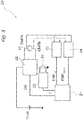
- FIG 3 is a schematic representation of a circuit device 20 for controlling a power-window apparatus with anti-pinch function.
- the control circuit comprises a microprocessor 21, which sends PWM control signals, designated by DS in Figure 3 , with ON and OFF times t 1 and t 2 , to an H-bridge circuit 22, in particular supplied by a battery voltage Vbatt, which drives the electric motor 10.
- EMFA and EMFB Acquired on the terminals A and B of the motor 10 are respective voltage values EMFA and EMFB, which are sent both to a first conditioning operational circuit 23 that computes the difference EMFA - EMFB, corresponding to a rotation of the motor for raising the window F, referred to as window-up signal EMF UP , and to a second conditioning operational circuit 24, which computes the difference EMFB - EMFA, referred to as window-down signal EMF DOWN , corresponding to a rotation of the motor for lowering the window F.
- first conditioning operational circuit 23 that computes the difference EMFA - EMFB, corresponding to a rotation of the motor for raising the window F
- EMF UP window-up signal
- EMF DOWN window-down signal
- the signals EMF UP and EMF DOWN are sent to the microprocessor 21, which receives, via a third conditioning operational circuit 25, a value of current I of the motor, measured via a shunt resistance 26 set between the H-bridge driving circuit 22 and ground.
- the current I of the motor 10 is calculated by the circuit 25 as ratio of the voltage detected by the circuit 25 across the shunt resistance 26 and the value of the shunt resistance 26 itself.
- Figure 4 shows a flowchart that represents operation of the system.
- a step 110 the current position of the window F is read by the microprocessor 21. This is done by reading, for example, a counter available in the microprocessor, which records the incremental displacements.
- a timer is started in the microprocessor 21.
- a value of back electromotive force of the motor 10 is read, in particular the window-up signal EMF UP or the window-down signal EMF DOWN according to the direction of displacement of the window F, up or down.
- a mean value E m is then calculated of the back electromotive force determined by the duty cycle, i.e., by the ON time t 1 and OFF time t 2 , of PWM driving, i.e., of the signal DS.
- This value is a mean value E m in so far as, in actual fact, the value calculated is a value averaged over a plurality of periods of the PWM signal, for example taking into account the value of back electromotive force in the current period and the value of the previous period, and dividing by two.
- a subsequent step 145 reading of the current I of the motor 10 is carried out via the microprocessor 21, and a condition is verified, whereby, as long as the current I of the motor 10 measured in the mean time by the microprocessor 21 is lower than a given threshold current I th , or else - in a preferred variant that envisages joint checking of the state of activation of an electromechanical pushbutton for moving the window F - as long as the current I is lower than a given threshold current I th or the electromechanical pushbutton is activated for moving the window, the step 130 of measurement of the back electromotive force E m is repeated.
- control passes to a step 150 where the timer is stopped, the timer (in particular, via its own count) supplying a time t w of sliding of the window F, and the mean value of back electromotive force E m is acquired during execution of step 150.
- a step 160 the linear velocity v of the window F is then calculated as ratio between the back electromotive force E m measured and a coefficient of proportionality K e .
- a step 170 the position X of the window F is then calculated as product of the linear velocity v of the window F and of the time t w of sliding of the window F. This position is calculated in an incremental way with respect to the position read in step 110.
- the procedure for reading the position is in fact incremental, and the current position at the end of the procedure 100 applied must be stored. The next reading must be added or subtracted (according to the direction) to/from the value previously stored.
- E K e ⁇ .
- ⁇ m E m /K e
- the position X is equal to t w ⁇ m , i.e., to the product of the mean angular velocity ⁇ m of the motor and of the time t w of sliding of the window F.
- the factor of conversion between rotation of the motor 10 and linear translation of the window F is constant, it is possible to operate with the linear velocity v, as indicated in steps 160, 170, thus obtaining, as illustrated hereinafter, the coefficient of proportionality K e via a calibration that takes into account the linear velocity v.
- step 180 it is evaluated whether the position X of the window F obtained in step 170 falls within the anti-pinch zone APZ. If so, the direction of the motor 10 is reversed in step 190. If not, the position X is acquired, and control returns to step 110. It is to be noted that passage through step 190 is performed only if the movement of the window F is upwards.
- the back electromotive force E m is measured, with a given sampling interval, until a condition on the current (possibly combined with a check on the pushbuttons) that identifies a possible pinching or jamming is verified, whilst a timer started in step 120 counts the time interval during which the measurement is active, i.e., the program cycles between steps 130, 140, and 145.
- the timer 150 stops, and, on the basis of the time measured and the back electromotive force E m measured at the moment of arrest of the timer, the position X of the window F is calculated and is compared with the anti-pinch zone APZ.
- the control circuit 20 carries out the anti-pinch function, with introduction of the parameter current I.
- the d.c. electric motor absorbs, for example, a current I of approximately 4 A to 6 A; in the case of blocking, the current I rapidly passes to a value of approximately 12 A to 15 A.
- the window F is in the anti-pinch zone APZ, namely, comprised between 4 mm and 200 mm from the top end-of-travel, when a sudden increase, beyond the threshold, in the value of current I during raising of the window F, is detected by the microprocessor 21 of the electronic control system 20 of Figure 3 , the direction of motion of the window F is reversed (i.e., the window is lowered), thus enabling removal of the obstacle.
- Illustrated in Figure 5 are the plots of the voltage V of the motor 10 and of the current I of the motor 10. Designated by CR are the values of current during normal operation of the motor 10, whereas CB designates the sudden increase in the current I of the motor until the threshold value I th is exceeded, beyond which the microprocessor 10 drives reversal of rotation of the motor 10 (step 190 of Figure 4 ).
- the above procedure of calibration of the coefficient K e is performed as follows: in a first step, the value of the back electromotive force E is read after a full cycle of movement of the window F (for example, window up to top end-of-travel and window down to bottom end-of-travel), with a corresponding path P equal to 2 ⁇ CF, i.e., twice the travel CF of the window F, for a cycle time t c , which can be measured, for example, by the same timer as that of step 120 (in step 145 - in this case, arrest of movement at end-of-travel enables step 150 of arrest of the timer), and a value of back electromotive force E m is obtained for upward sliding of the window (EMF UP ) and a value of back electromotive force E m is obtained for downward sliding of the window (EMF DOWN ) .
- a full cycle of movement of the window F for example, window up to top end-of-travel and window down to bottom end-of-travel
- the back electromotive force E is preferably calculated distinguishing between upward sliding EMF UP and downward sliding EMF DOWN , which are read during a cycle.
- the electromotive force E corresponding upward sliding EMF UP is calculated for a movement along half of the path P, i.e., P/2 (equal to the travel CF) during a window-up cycle time t cup .
- P the electromotive force
- v up v up P / 2 t cup
- K eup K eup EMF UP / v up
- the coefficient of proportionality K e used by the procedure 100 is finally calculated as average between the window-up coefficient K eup and the window-down coefficient K edown .
- the device and method described advantageously enable exact determination of the position of the window along its path without the aid of external sensor means using the back electromotive force of the motor. This results in a simplification (from the automotive standpoint) of the system for verifying the position of the window, in so far as no sensor is envisaged, or rather the motor operates as sensor.
- this determination of the position is advantageously rendered independent of the typical (and parasitic) parameters of the system, in particular of the electric motor, thanks to a self-calibration procedure, so that there is no constraint on the choice of the electric motor used.
Landscapes
- Engineering & Computer Science (AREA)
- Power Engineering (AREA)
- Mechanical Engineering (AREA)
- Power-Operated Mechanisms For Wings (AREA)
- Switches With Compound Operations (AREA)
- Lighting Device Outwards From Vehicle And Optical Signal (AREA)
Claims (8)
- Klemmschutzschaltungsvorrichtung für eine Einrichtung zur automatischen Bewegung von Schiebefenstern in einem Kraftfahrzeug, insbesondere für eine elektrische Fensterhebereinrichtung, mit einem elektrischen Gleichstrommotor (10), der ein Fenster (F) bewegt, so dass es entlang von Führungen gleitet, wobei die Vorrichtung (20) ein elektronisches Steuermodul (21) zur Steuerung des elektrischen Gleichstrommotors (10), insbesondere einen Mikroprozessor, umfasst, wobei das elektronische Steuermodul (21) zur Messung eines Stroms (I) des Motors (10) und zur Messung der Position (X) des Fensters (F) ausgebildet ist, wobei das Steuermodul (21) außerdem ausgebildet ist, eine Umkehr (190) des Betriebs des Elektromotors (10) zu steuern, wenn festgestellt wird (180), dass der Strom (I) höher als ein Schwellenstrom (Ith) ist und die Position (X) des Fensters (F) in einen bestimmten Bereich (APZ) eines Bewegungspfads (P) des Fensters fällt,
wobei:
die Klemmschutzschaltungsvorrichtung (20) ausgebildet ist, eine elektromotorische Gegenkraft (E; Em) des Motors (10) zu messen (130) und einen Wert der elektromotorischen Gegenkraft (E; Em) zu erhalten (140), und das elektronische Steuermodul (21) ausgebildet ist, die Position des Fensters (F) als Funktion des gemessenen Werts der elektromotorischen Gegenkraft (E; Em) des Motors (10) zu berechnen (180), so dass es ohne die Hilfe externer Sensoren arbeitet. - Vorrichtung nach Anspruch 1, dadurch gekennzeichnet, dass sie ein Modul (25, 26) zum Messen des Stroms (I) des Elektromotors (10) und entsprechende Module (23, 24) zum Messen der elektromotorischen Gegenkraft (EMFUP) des Motors (10) während des Aufwärtsgleitens oder in Richtung des Endes des Schließweges (CFu) und der elektromotorischen Gegenkraft (EMFDOWN) des Motors (10) während des Abwärtsgleitens oder in Richtung des Endes des Öffnungsweges (CFd) des Fensters (F) umfasst.
- Vorrichtung nach Anspruch 1, dadurch gekennzeichnet, dass das elektronische Steuermodul (21) ausgebildet ist:eine Startposition des Fensters (F) zu erfassen (110);einen Zeitgeber zu starten (120);einen Wert der elektromotorischen Gegenkraft (E; EMFUP, EMFDOWN) zu erfassen (130);einen Mittelwert (Em) der elektromotorischen Gegenkraft zu berechnen (140);den Wert des Stroms (I) des Motors (10) zu überprüfen (145) und,wenn der Strom (I) kleiner als ein Schwellenstrom (Ith) ist, zu dem Schritt (130) des Erfassens des Wertes der elektromotorischen Gegenkraft (E; EMFUP, EMFDOWN) zurückzukehren;wenn der Strom (I) des Motors größer als ein Schwellenstrom (Ith) ist, den Zeitgeber anzuhalten (150), und dadurch eine Zeit (tw) für das Gleiten des Fensters (F) zu erhalten;eine Geschwindigkeit (v) des Fensters als Verhältnis zwischen der gemessenen elektromotorischen Gegenkraft (Em) und einem Proportionalitätskoeffizienten (Ke) zu berechnen (160), der der automatischen Bewegungsvorrichtung (50) zugeordnet ist; unddie Position des Fensters (F) als Produkt der Geschwindigkeit (v) des Fensters und der Zeit (tw) des Gleitens des Fensters (F) zu berechnen (170).
- Vorrichtung nach Anspruch 3, dadurch gekennzeichnet, dass:
der Vorgang des Überprüfens (145) des Wertes des Stroms (I) des Motors (10) außerdem das gemeinsame Überprüfen (145) des Betriebszustands eines elektromechanischen Druckknopfes zum Bewegen des Fensters (F) umfasst. - Vorrichtung nach Anspruch 3 oder Anspruch 4, dadurch gekennzeichnet, dass das Steuermodul (21) zur Berechnung des Proportionalitätskoeffizienten (Ke) des Systems mittels der folgenden Schritte ausgebildet ist:Erfassen des Wertes der elektromotorischen Gegenkraft (Em) nach Abschluss eines vollen Bewegungszyklus des Fensters mit einem entsprechenden Weg (P) in einer gemessenen Zykluszeit (tc);Berechnen einer Geschwindigkeit (v) des Fensters als Verhältnis zwischen dem Weg (P) und der Zykluszeit (tc); undBerechnen des Proportionalitätskoeffizienten (Ke) als das Verhältnis zwischen der gemessenen elektromotorischen Gegenkraft (E) und der Geschwindigkeit (v).
- Vorrichtung nach Anspruch 5, dadurch gekennzeichnet, dass sie umfasst:Erfassen der elektromotorischen Gegenkraft für das Aufwärtsgleiten (EMFUP) des Fensters (F), Messen einer Fenster-Aufwärts Zykluszeit (tcup) und Berechnen einer entsprechenden Fenster-Aufwärts Geschwindigkeit (vup) und einer entsprechenden Fenster-Aufwärts-Konstante (Keup);Erfassen der elektromotorischen Kraft für das Abwärtsgleiten (EMFDOWN) des Fensters (F), Messen einer Fenster-Abwärts Zykluszeit (tcdown) und Berechnen einer entsprechenden Fenster-Abwärts Geschwindigkeit (vdown) und einer entsprechenden Fenster-Abwärts Konstante (Kedown); undBerechnen des Proportionalitätskoeffizienten (Ke) als Mittelwert zwischen dem Fenster-Aufwärts Koeffizienten (Keup) und dem Fenster-Abwärts Koeffizienten (Kedown).
- Vorrichtung nach einem der vorhergehenden Ansprüche, dadurch gekennzeichnet, dass sie die Ansteuerung des Motors (10) mittels einer PWM-Modulation (DS) und die Messung der elektromotorischen Gegenkraft (E) zu dem Zeitpunkt umfasst, wenn die an den Anschlüssen des Motors (10) angelegte Spannung Null ist und ein induktiver Transient (TDL) des Motors (10) endet.
- Klemmschutzverfahren für eine Einrichtung zur automatischen Bewegung von Schiebefenstern in einem Kraftfahrzeug, insbesondere für eine elektrische Fensterhebereinrichtung, dadurch gekennzeichnet, dass es eine Klemmschutzschaltungsvorrichtung nach einem der Ansprüche 1-7 verwendet, um eine oder mehrere der von dieser Vorrichtung ausgeführten Operationen zu realisieren.
Applications Claiming Priority (2)
| Application Number | Priority Date | Filing Date | Title |
|---|---|---|---|
| ITUB2015A005321A ITUB20155321A1 (it) | 2015-11-06 | 2015-11-06 | Dispositivo circuitale di anti-pizzicamento per apparato di movimentazione automatica di finestre scorrevoli in un autoveicolo, in particolare un apparato alza-cristallo automatico e relativo procedimento |
| PCT/IB2016/056588 WO2017077461A1 (en) | 2015-11-06 | 2016-11-02 | Anti-pinch circuit device for an apparaturs for auomatic movement of sliding windows in a motor vehicle, and corresponding method |
Publications (2)
| Publication Number | Publication Date |
|---|---|
| EP3371407A1 EP3371407A1 (de) | 2018-09-12 |
| EP3371407B1 true EP3371407B1 (de) | 2021-12-29 |
Family
ID=55410081
Family Applications (1)
| Application Number | Title | Priority Date | Filing Date |
|---|---|---|---|
| EP16810465.1A Active EP3371407B1 (de) | 2015-11-06 | 2016-11-02 | Klemmschutzschaltungsvorrichtung für eine vorrichtung zur automatischen bewegung von schiebefenstern bei einem kraftfahrzeug und entsprechendes verfahren |
Country Status (5)
| Country | Link |
|---|---|
| US (1) | US10851576B2 (de) |
| EP (1) | EP3371407B1 (de) |
| CN (1) | CN108350717B (de) |
| IT (1) | ITUB20155321A1 (de) |
| WO (1) | WO2017077461A1 (de) |
Families Citing this family (5)
| Publication number | Priority date | Publication date | Assignee | Title |
|---|---|---|---|---|
| CN110206438B (zh) * | 2019-05-16 | 2021-02-19 | 马瑞利汽车电子(广州)有限公司 | 一种车窗防夹标定装置 |
| EP3838639A1 (de) * | 2019-12-17 | 2021-06-23 | Inalfa Roof Systems Group B.V. | Offene dachanordnung zur verwendung in einem fahrzeug und verfahren zu deren betrieb |
| CN113037145A (zh) * | 2020-12-23 | 2021-06-25 | 盛视科技股份有限公司 | 一种电动门阻挡判断方法及系统 |
| CN113888799B (zh) * | 2021-09-25 | 2022-11-15 | 万事达(杭州)咖啡机有限公司 | 自动门的关门控制方法 |
| CN115682282A (zh) * | 2022-10-27 | 2023-02-03 | 天钥光电(湖北)股份有限公司 | 自清洁新风系统电流阈值的自适应调整方法 |
Family Cites Families (10)
| Publication number | Priority date | Publication date | Assignee | Title |
|---|---|---|---|---|
| GB2221769A (en) * | 1988-08-09 | 1990-02-14 | Austin Rover Group | Improvements in electric motor control |
| FR2734598B1 (fr) * | 1995-05-22 | 1997-07-18 | Faiveley Transport | Procede de commande electronique d'ouverture et/ou de fermeture d'une porte et dispositif pour sa mise en oeuvre |
| FR2806551B1 (fr) * | 2000-03-15 | 2002-05-10 | Valeo Electronique | Procedes et dispositifs pour le suivi de la rotation de moteurs electriques a courant continu |
| US6906487B2 (en) * | 2002-01-21 | 2005-06-14 | International Rectifier Corporation | Anti-pinch window drive circuit |
| EP1389817A1 (de) * | 2002-07-26 | 2004-02-18 | STMicroelectronics S.r.l. | Verfahren und Schaltung zur Erfassung von Drehmomentschwankungen eines elektrischen Gleichstrommotors |
| DE102006039257A1 (de) * | 2006-08-22 | 2008-02-28 | Robert Bosch Gmbh | Verstellvorrichtung für ein bewegliches Karosserieteil eines Kraftfahrzeugs sowie Verfahren zur Verstellung des beweglichen Karosserieteils |
| DE102009014264A1 (de) | 2008-09-12 | 2010-04-15 | Brose Fahrzeugteile Gmbh & Co. Kommanditgesellschaft, Hallstadt | Verfahren und Vorrichtung zur Verarbeitung eines Stromrippel aufweisenden Motorsignals eines Gleichstrommotors |
| BRPI1009492A8 (pt) * | 2009-03-16 | 2016-10-11 | Brose Fahrzeugteile | correção de erros de contagem na avaliação de ondulações de corrente em um motor de corrente contínua |
| CN101704357B (zh) * | 2009-11-16 | 2011-05-04 | 杭州电子科技大学 | 用于汽车电动天窗防夹的方法 |
| JP6155175B2 (ja) * | 2013-11-18 | 2017-06-28 | 株式会社マキタ | 電動工具の制動装置 |
-
2015
- 2015-11-06 IT ITUB2015A005321A patent/ITUB20155321A1/it unknown
-
2016
- 2016-11-02 US US15/767,335 patent/US10851576B2/en active Active
- 2016-11-02 EP EP16810465.1A patent/EP3371407B1/de active Active
- 2016-11-02 CN CN201680064793.0A patent/CN108350717B/zh active Active
- 2016-11-02 WO PCT/IB2016/056588 patent/WO2017077461A1/en not_active Ceased
Also Published As
| Publication number | Publication date |
|---|---|
| ITUB20155321A1 (it) | 2017-05-06 |
| WO2017077461A1 (en) | 2017-05-11 |
| US10851576B2 (en) | 2020-12-01 |
| CN108350717A (zh) | 2018-07-31 |
| US20180298668A1 (en) | 2018-10-18 |
| CN108350717B (zh) | 2020-09-15 |
| EP3371407A1 (de) | 2018-09-12 |
Similar Documents
| Publication | Publication Date | Title |
|---|---|---|
| EP3371407B1 (de) | Klemmschutzschaltungsvorrichtung für eine vorrichtung zur automatischen bewegung von schiebefenstern bei einem kraftfahrzeug und entsprechendes verfahren | |
| US11655661B2 (en) | Anti-pinch method for an apparatus for automatic movement of sliding windows in a motor vehicle, in particular a power-window apparatus, and corresponding device | |
| CN111206838A (zh) | 一种纹波防夹位置补偿方法及装置 | |
| US6051945A (en) | Anti-pinch safety system for vehicle closure device | |
| JP4012573B2 (ja) | 車両ドアのウインドガラスの運動の制御方法 | |
| US6222362B1 (en) | Method for detecting the position and direction of motion of a moving part mounted on an electric motor | |
| EP2109211B1 (de) | System und Verfahren zur Bestimmung der Position oder der Drehzahl eines kommutierten Gleichstrommotors mit Fehlerkorrektur | |
| US7445035B2 (en) | Process for initializing a roller shutter | |
| US20050203690A1 (en) | Controlling device of a regulating device of a motor vehicle | |
| CN103392048B (zh) | 车辆的开闭部的控制装置以及控制车辆的开闭部的方法 | |
| JP2005351042A (ja) | 開閉体制御装置 | |
| CN105649463A (zh) | 可开闭构件控制设备 | |
| CN102575494B (zh) | 夹物检测方法、夹物检测装置的设定方法、夹物检测装置、开闭控制装置 | |
| US9267318B2 (en) | Method and apparatus for providing an indication of movement, particularly for recognition of blocking in a locking system | |
| KR20160098052A (ko) | 시스템의 장치에서 모터의 움직임을 감지 및 방지하기 위한 장치 및 방법 | |
| US6657407B2 (en) | Method for determining the rotational position of the drive shaft of a direct current motor | |
| JP2013155535A (ja) | シャッター装置の初期設定モードにおける上限位置・下限位置設定装置及び方法 | |
| JPH10331521A (ja) | パワーウインドウ制御装置 | |
| US8222843B2 (en) | Method for determining the angular position of the rotor of a mechanically commutated d.c. servo motor | |
| US7294981B2 (en) | Method of determining the position of the shaft of a drive motor for a roller blind | |
| JPH09128002A (ja) | 構成部材の運動行程を監視するための方法 | |
| CN101910539B (zh) | 用于确定通过电机而运动的闭合件的参考位置的方法和装置 | |
| JPH0512464Y2 (de) | ||
| JP2005307563A (ja) | パワーウインド用安全装置 | |
| JP2003336444A (ja) | 車両用パワーウインド装置 |
Legal Events
| Date | Code | Title | Description |
|---|---|---|---|
| STAA | Information on the status of an ep patent application or granted ep patent |
Free format text: STATUS: UNKNOWN |
|
| STAA | Information on the status of an ep patent application or granted ep patent |
Free format text: STATUS: THE INTERNATIONAL PUBLICATION HAS BEEN MADE |
|
| PUAI | Public reference made under article 153(3) epc to a published international application that has entered the european phase |
Free format text: ORIGINAL CODE: 0009012 |
|
| STAA | Information on the status of an ep patent application or granted ep patent |
Free format text: STATUS: REQUEST FOR EXAMINATION WAS MADE |
|
| 17P | Request for examination filed |
Effective date: 20180320 |
|
| AK | Designated contracting states |
Kind code of ref document: A1 Designated state(s): AL AT BE BG CH CY CZ DE DK EE ES FI FR GB GR HR HU IE IS IT LI LT LU LV MC MK MT NL NO PL PT RO RS SE SI SK SM TR |
|
| AX | Request for extension of the european patent |
Extension state: BA ME |
|
| DAV | Request for validation of the european patent (deleted) | ||
| DAX | Request for extension of the european patent (deleted) | ||
| GRAP | Despatch of communication of intention to grant a patent |
Free format text: ORIGINAL CODE: EPIDOSNIGR1 |
|
| STAA | Information on the status of an ep patent application or granted ep patent |
Free format text: STATUS: GRANT OF PATENT IS INTENDED |
|
| INTG | Intention to grant announced |
Effective date: 20210730 |
|
| RAP3 | Party data changed (applicant data changed or rights of an application transferred) |
Owner name: MARELLI AUTOMOTIVE LIGHTING ITALY S.P.A. |
|
| GRAS | Grant fee paid |
Free format text: ORIGINAL CODE: EPIDOSNIGR3 |
|
| GRAA | (expected) grant |
Free format text: ORIGINAL CODE: 0009210 |
|
| STAA | Information on the status of an ep patent application or granted ep patent |
Free format text: STATUS: THE PATENT HAS BEEN GRANTED |
|
| RIN1 | Information on inventor provided before grant (corrected) |
Inventor name: GALLO, CARLO Inventor name: VAI, CARLO Inventor name: BUSSI, ANDREA Inventor name: NOVELLO, ANDREA |
|
| AK | Designated contracting states |
Kind code of ref document: B1 Designated state(s): AL AT BE BG CH CY CZ DE DK EE ES FI FR GB GR HR HU IE IS IT LI LT LU LV MC MK MT NL NO PL PT RO RS SE SI SK SM TR |
|
| REG | Reference to a national code |
Ref country code: GB Ref legal event code: FG4D |
|
| REG | Reference to a national code |
Ref country code: CH Ref legal event code: EP |
|
| REG | Reference to a national code |
Ref country code: DE Ref legal event code: R096 Ref document number: 602016067886 Country of ref document: DE |
|
| REG | Reference to a national code |
Ref country code: AT Ref legal event code: REF Ref document number: 1458786 Country of ref document: AT Kind code of ref document: T Effective date: 20220115 |
|
| REG | Reference to a national code |
Ref country code: IE Ref legal event code: FG4D |
|
| REG | Reference to a national code |
Ref country code: LT Ref legal event code: MG9D |
|
| PG25 | Lapsed in a contracting state [announced via postgrant information from national office to epo] |
Ref country code: RS Free format text: LAPSE BECAUSE OF FAILURE TO SUBMIT A TRANSLATION OF THE DESCRIPTION OR TO PAY THE FEE WITHIN THE PRESCRIBED TIME-LIMIT Effective date: 20211229 Ref country code: LT Free format text: LAPSE BECAUSE OF FAILURE TO SUBMIT A TRANSLATION OF THE DESCRIPTION OR TO PAY THE FEE WITHIN THE PRESCRIBED TIME-LIMIT Effective date: 20211229 Ref country code: FI Free format text: LAPSE BECAUSE OF FAILURE TO SUBMIT A TRANSLATION OF THE DESCRIPTION OR TO PAY THE FEE WITHIN THE PRESCRIBED TIME-LIMIT Effective date: 20211229 Ref country code: BG Free format text: LAPSE BECAUSE OF FAILURE TO SUBMIT A TRANSLATION OF THE DESCRIPTION OR TO PAY THE FEE WITHIN THE PRESCRIBED TIME-LIMIT Effective date: 20220329 |
|
| REG | Reference to a national code |
Ref country code: NL Ref legal event code: MP Effective date: 20211229 |
|
| REG | Reference to a national code |
Ref country code: AT Ref legal event code: MK05 Ref document number: 1458786 Country of ref document: AT Kind code of ref document: T Effective date: 20211229 |
|
| PG25 | Lapsed in a contracting state [announced via postgrant information from national office to epo] |
Ref country code: SE Free format text: LAPSE BECAUSE OF FAILURE TO SUBMIT A TRANSLATION OF THE DESCRIPTION OR TO PAY THE FEE WITHIN THE PRESCRIBED TIME-LIMIT Effective date: 20211229 Ref country code: NO Free format text: LAPSE BECAUSE OF FAILURE TO SUBMIT A TRANSLATION OF THE DESCRIPTION OR TO PAY THE FEE WITHIN THE PRESCRIBED TIME-LIMIT Effective date: 20220329 Ref country code: LV Free format text: LAPSE BECAUSE OF FAILURE TO SUBMIT A TRANSLATION OF THE DESCRIPTION OR TO PAY THE FEE WITHIN THE PRESCRIBED TIME-LIMIT Effective date: 20211229 Ref country code: HR Free format text: LAPSE BECAUSE OF FAILURE TO SUBMIT A TRANSLATION OF THE DESCRIPTION OR TO PAY THE FEE WITHIN THE PRESCRIBED TIME-LIMIT Effective date: 20211229 Ref country code: GR Free format text: LAPSE BECAUSE OF FAILURE TO SUBMIT A TRANSLATION OF THE DESCRIPTION OR TO PAY THE FEE WITHIN THE PRESCRIBED TIME-LIMIT Effective date: 20220330 |
|
| PG25 | Lapsed in a contracting state [announced via postgrant information from national office to epo] |
Ref country code: NL Free format text: LAPSE BECAUSE OF FAILURE TO SUBMIT A TRANSLATION OF THE DESCRIPTION OR TO PAY THE FEE WITHIN THE PRESCRIBED TIME-LIMIT Effective date: 20211229 |
|
| PG25 | Lapsed in a contracting state [announced via postgrant information from national office to epo] |
Ref country code: SM Free format text: LAPSE BECAUSE OF FAILURE TO SUBMIT A TRANSLATION OF THE DESCRIPTION OR TO PAY THE FEE WITHIN THE PRESCRIBED TIME-LIMIT Effective date: 20211229 Ref country code: SK Free format text: LAPSE BECAUSE OF FAILURE TO SUBMIT A TRANSLATION OF THE DESCRIPTION OR TO PAY THE FEE WITHIN THE PRESCRIBED TIME-LIMIT Effective date: 20211229 Ref country code: RO Free format text: LAPSE BECAUSE OF FAILURE TO SUBMIT A TRANSLATION OF THE DESCRIPTION OR TO PAY THE FEE WITHIN THE PRESCRIBED TIME-LIMIT Effective date: 20211229 Ref country code: PT Free format text: LAPSE BECAUSE OF FAILURE TO SUBMIT A TRANSLATION OF THE DESCRIPTION OR TO PAY THE FEE WITHIN THE PRESCRIBED TIME-LIMIT Effective date: 20220429 Ref country code: ES Free format text: LAPSE BECAUSE OF FAILURE TO SUBMIT A TRANSLATION OF THE DESCRIPTION OR TO PAY THE FEE WITHIN THE PRESCRIBED TIME-LIMIT Effective date: 20211229 Ref country code: EE Free format text: LAPSE BECAUSE OF FAILURE TO SUBMIT A TRANSLATION OF THE DESCRIPTION OR TO PAY THE FEE WITHIN THE PRESCRIBED TIME-LIMIT Effective date: 20211229 Ref country code: CZ Free format text: LAPSE BECAUSE OF FAILURE TO SUBMIT A TRANSLATION OF THE DESCRIPTION OR TO PAY THE FEE WITHIN THE PRESCRIBED TIME-LIMIT Effective date: 20211229 |
|
| PG25 | Lapsed in a contracting state [announced via postgrant information from national office to epo] |
Ref country code: PL Free format text: LAPSE BECAUSE OF FAILURE TO SUBMIT A TRANSLATION OF THE DESCRIPTION OR TO PAY THE FEE WITHIN THE PRESCRIBED TIME-LIMIT Effective date: 20211229 Ref country code: AT Free format text: LAPSE BECAUSE OF FAILURE TO SUBMIT A TRANSLATION OF THE DESCRIPTION OR TO PAY THE FEE WITHIN THE PRESCRIBED TIME-LIMIT Effective date: 20211229 |
|
| PG25 | Lapsed in a contracting state [announced via postgrant information from national office to epo] |
Ref country code: IS Free format text: LAPSE BECAUSE OF FAILURE TO SUBMIT A TRANSLATION OF THE DESCRIPTION OR TO PAY THE FEE WITHIN THE PRESCRIBED TIME-LIMIT Effective date: 20220429 |
|
| REG | Reference to a national code |
Ref country code: DE Ref legal event code: R097 Ref document number: 602016067886 Country of ref document: DE |
|
| PG25 | Lapsed in a contracting state [announced via postgrant information from national office to epo] |
Ref country code: DK Free format text: LAPSE BECAUSE OF FAILURE TO SUBMIT A TRANSLATION OF THE DESCRIPTION OR TO PAY THE FEE WITHIN THE PRESCRIBED TIME-LIMIT Effective date: 20211229 Ref country code: AL Free format text: LAPSE BECAUSE OF FAILURE TO SUBMIT A TRANSLATION OF THE DESCRIPTION OR TO PAY THE FEE WITHIN THE PRESCRIBED TIME-LIMIT Effective date: 20211229 |
|
| PLBE | No opposition filed within time limit |
Free format text: ORIGINAL CODE: 0009261 |
|
| STAA | Information on the status of an ep patent application or granted ep patent |
Free format text: STATUS: NO OPPOSITION FILED WITHIN TIME LIMIT |
|
| 26N | No opposition filed |
Effective date: 20220930 |
|
| PG25 | Lapsed in a contracting state [announced via postgrant information from national office to epo] |
Ref country code: SI Free format text: LAPSE BECAUSE OF FAILURE TO SUBMIT A TRANSLATION OF THE DESCRIPTION OR TO PAY THE FEE WITHIN THE PRESCRIBED TIME-LIMIT Effective date: 20211229 |
|
| PG25 | Lapsed in a contracting state [announced via postgrant information from national office to epo] |
Ref country code: MC Free format text: LAPSE BECAUSE OF FAILURE TO SUBMIT A TRANSLATION OF THE DESCRIPTION OR TO PAY THE FEE WITHIN THE PRESCRIBED TIME-LIMIT Effective date: 20211229 |
|
| REG | Reference to a national code |
Ref country code: CH Ref legal event code: PL |
|
| REG | Reference to a national code |
Ref country code: BE Ref legal event code: MM Effective date: 20221130 |
|
| PG25 | Lapsed in a contracting state [announced via postgrant information from national office to epo] |
Ref country code: LI Free format text: LAPSE BECAUSE OF NON-PAYMENT OF DUE FEES Effective date: 20221130 Ref country code: CH Free format text: LAPSE BECAUSE OF NON-PAYMENT OF DUE FEES Effective date: 20221130 |
|
| PG25 | Lapsed in a contracting state [announced via postgrant information from national office to epo] |
Ref country code: LU Free format text: LAPSE BECAUSE OF NON-PAYMENT OF DUE FEES Effective date: 20221102 |
|
| PG25 | Lapsed in a contracting state [announced via postgrant information from national office to epo] |
Ref country code: IE Free format text: LAPSE BECAUSE OF NON-PAYMENT OF DUE FEES Effective date: 20221102 |
|
| PG25 | Lapsed in a contracting state [announced via postgrant information from national office to epo] |
Ref country code: BE Free format text: LAPSE BECAUSE OF NON-PAYMENT OF DUE FEES Effective date: 20221130 |
|
| PG25 | Lapsed in a contracting state [announced via postgrant information from national office to epo] |
Ref country code: HU Free format text: LAPSE BECAUSE OF FAILURE TO SUBMIT A TRANSLATION OF THE DESCRIPTION OR TO PAY THE FEE WITHIN THE PRESCRIBED TIME-LIMIT; INVALID AB INITIO Effective date: 20161102 |
|
| PG25 | Lapsed in a contracting state [announced via postgrant information from national office to epo] |
Ref country code: CY Free format text: LAPSE BECAUSE OF FAILURE TO SUBMIT A TRANSLATION OF THE DESCRIPTION OR TO PAY THE FEE WITHIN THE PRESCRIBED TIME-LIMIT Effective date: 20211229 |
|
| PG25 | Lapsed in a contracting state [announced via postgrant information from national office to epo] |
Ref country code: MK Free format text: LAPSE BECAUSE OF FAILURE TO SUBMIT A TRANSLATION OF THE DESCRIPTION OR TO PAY THE FEE WITHIN THE PRESCRIBED TIME-LIMIT Effective date: 20211229 |
|
| PG25 | Lapsed in a contracting state [announced via postgrant information from national office to epo] |
Ref country code: MT Free format text: LAPSE BECAUSE OF FAILURE TO SUBMIT A TRANSLATION OF THE DESCRIPTION OR TO PAY THE FEE WITHIN THE PRESCRIBED TIME-LIMIT Effective date: 20211229 |
|
| PG25 | Lapsed in a contracting state [announced via postgrant information from national office to epo] |
Ref country code: TR Free format text: LAPSE BECAUSE OF FAILURE TO SUBMIT A TRANSLATION OF THE DESCRIPTION OR TO PAY THE FEE WITHIN THE PRESCRIBED TIME-LIMIT Effective date: 20211229 |
|
| PGFP | Annual fee paid to national office [announced via postgrant information from national office to epo] |
Ref country code: DE Payment date: 20251022 Year of fee payment: 10 |
|
| PGFP | Annual fee paid to national office [announced via postgrant information from national office to epo] |
Ref country code: GB Payment date: 20251023 Year of fee payment: 10 |
|
| PGFP | Annual fee paid to national office [announced via postgrant information from national office to epo] |
Ref country code: IT Payment date: 20251022 Year of fee payment: 10 |
|
| PGFP | Annual fee paid to national office [announced via postgrant information from national office to epo] |
Ref country code: FR Payment date: 20251023 Year of fee payment: 10 |