EP3372261A1 - Dispositif de commande/réglage d'un taux d'ultrafiltration dans un dispositif de dialyse à l'aide d'une différence déterminée d'un premier et d'un deuxième flux de liquide - Google Patents
Dispositif de commande/réglage d'un taux d'ultrafiltration dans un dispositif de dialyse à l'aide d'une différence déterminée d'un premier et d'un deuxième flux de liquide Download PDFInfo
- Publication number
- EP3372261A1 EP3372261A1 EP18163445.2A EP18163445A EP3372261A1 EP 3372261 A1 EP3372261 A1 EP 3372261A1 EP 18163445 A EP18163445 A EP 18163445A EP 3372261 A1 EP3372261 A1 EP 3372261A1
- Authority
- EP
- European Patent Office
- Prior art keywords
- channel
- dialysate
- dialysis
- blood
- sensor
- Prior art date
- Legal status (The legal status is an assumption and is not a legal conclusion. Google has not performed a legal analysis and makes no representation as to the accuracy of the status listed.)
- Withdrawn
Links
Images


Classifications
-
- A—HUMAN NECESSITIES
- A61—MEDICAL OR VETERINARY SCIENCE; HYGIENE
- A61M—DEVICES FOR INTRODUCING MEDIA INTO, OR ONTO, THE BODY; DEVICES FOR TRANSDUCING BODY MEDIA OR FOR TAKING MEDIA FROM THE BODY; DEVICES FOR PRODUCING OR ENDING SLEEP OR STUPOR
- A61M1/00—Suction or pumping devices for medical purposes; Devices for carrying-off, for treatment of, or for carrying-over, body-liquids; Drainage systems
- A61M1/34—Filtering material out of the blood by passing it through a membrane, i.e. hemofiltration or diafiltration
-
- F—MECHANICAL ENGINEERING; LIGHTING; HEATING; WEAPONS; BLASTING
- F17—STORING OR DISTRIBUTING GASES OR LIQUIDS
- F17D—PIPE-LINE SYSTEMS; PIPE-LINES
- F17D1/00—Pipe-line systems
-
- A—HUMAN NECESSITIES
- A61—MEDICAL OR VETERINARY SCIENCE; HYGIENE
- A61M—DEVICES FOR INTRODUCING MEDIA INTO, OR ONTO, THE BODY; DEVICES FOR TRANSDUCING BODY MEDIA OR FOR TAKING MEDIA FROM THE BODY; DEVICES FOR PRODUCING OR ENDING SLEEP OR STUPOR
- A61M1/00—Suction or pumping devices for medical purposes; Devices for carrying-off, for treatment of, or for carrying-over, body-liquids; Drainage systems
- A61M1/14—Dialysis systems; Artificial kidneys; Blood oxygenators ; Reciprocating systems for treatment of body fluids, e.g. single needle systems for hemofiltration or pheresis
- A61M1/15—Dialysis systems; Artificial kidneys; Blood oxygenators ; Reciprocating systems for treatment of body fluids, e.g. single needle systems for hemofiltration or pheresis with a cassette forming partially or totally the flow circuit for the treating fluid, e.g. the dialysate fluid circuit or the treating gas circuit
- A61M1/154—Dialysis systems; Artificial kidneys; Blood oxygenators ; Reciprocating systems for treatment of body fluids, e.g. single needle systems for hemofiltration or pheresis with a cassette forming partially or totally the flow circuit for the treating fluid, e.g. the dialysate fluid circuit or the treating gas circuit with sensing means or components thereof
-
- A—HUMAN NECESSITIES
- A61—MEDICAL OR VETERINARY SCIENCE; HYGIENE
- A61M—DEVICES FOR INTRODUCING MEDIA INTO, OR ONTO, THE BODY; DEVICES FOR TRANSDUCING BODY MEDIA OR FOR TAKING MEDIA FROM THE BODY; DEVICES FOR PRODUCING OR ENDING SLEEP OR STUPOR
- A61M1/00—Suction or pumping devices for medical purposes; Devices for carrying-off, for treatment of, or for carrying-over, body-liquids; Drainage systems
- A61M1/14—Dialysis systems; Artificial kidneys; Blood oxygenators ; Reciprocating systems for treatment of body fluids, e.g. single needle systems for hemofiltration or pheresis
- A61M1/15—Dialysis systems; Artificial kidneys; Blood oxygenators ; Reciprocating systems for treatment of body fluids, e.g. single needle systems for hemofiltration or pheresis with a cassette forming partially or totally the flow circuit for the treating fluid, e.g. the dialysate fluid circuit or the treating gas circuit
- A61M1/155—Dialysis systems; Artificial kidneys; Blood oxygenators ; Reciprocating systems for treatment of body fluids, e.g. single needle systems for hemofiltration or pheresis with a cassette forming partially or totally the flow circuit for the treating fluid, e.g. the dialysate fluid circuit or the treating gas circuit with treatment-fluid pumping means or components thereof
-
- A—HUMAN NECESSITIES
- A61—MEDICAL OR VETERINARY SCIENCE; HYGIENE
- A61M—DEVICES FOR INTRODUCING MEDIA INTO, OR ONTO, THE BODY; DEVICES FOR TRANSDUCING BODY MEDIA OR FOR TAKING MEDIA FROM THE BODY; DEVICES FOR PRODUCING OR ENDING SLEEP OR STUPOR
- A61M1/00—Suction or pumping devices for medical purposes; Devices for carrying-off, for treatment of, or for carrying-over, body-liquids; Drainage systems
- A61M1/14—Dialysis systems; Artificial kidneys; Blood oxygenators ; Reciprocating systems for treatment of body fluids, e.g. single needle systems for hemofiltration or pheresis
- A61M1/16—Dialysis systems; Artificial kidneys; Blood oxygenators ; Reciprocating systems for treatment of body fluids, e.g. single needle systems for hemofiltration or pheresis with membranes
- A61M1/1601—Control or regulation
- A61M1/1603—Regulation parameters
- A61M1/1605—Physical characteristics of the dialysate fluid
-
- A—HUMAN NECESSITIES
- A61—MEDICAL OR VETERINARY SCIENCE; HYGIENE
- A61M—DEVICES FOR INTRODUCING MEDIA INTO, OR ONTO, THE BODY; DEVICES FOR TRANSDUCING BODY MEDIA OR FOR TAKING MEDIA FROM THE BODY; DEVICES FOR PRODUCING OR ENDING SLEEP OR STUPOR
- A61M1/00—Suction or pumping devices for medical purposes; Devices for carrying-off, for treatment of, or for carrying-over, body-liquids; Drainage systems
- A61M1/14—Dialysis systems; Artificial kidneys; Blood oxygenators ; Reciprocating systems for treatment of body fluids, e.g. single needle systems for hemofiltration or pheresis
- A61M1/16—Dialysis systems; Artificial kidneys; Blood oxygenators ; Reciprocating systems for treatment of body fluids, e.g. single needle systems for hemofiltration or pheresis with membranes
- A61M1/1621—Constructional aspects thereof
- A61M1/1647—Constructional aspects thereof with flow rate measurement of the dialysis fluid, upstream and downstream of the dialyser
-
- A—HUMAN NECESSITIES
- A61—MEDICAL OR VETERINARY SCIENCE; HYGIENE
- A61M—DEVICES FOR INTRODUCING MEDIA INTO, OR ONTO, THE BODY; DEVICES FOR TRANSDUCING BODY MEDIA OR FOR TAKING MEDIA FROM THE BODY; DEVICES FOR PRODUCING OR ENDING SLEEP OR STUPOR
- A61M1/00—Suction or pumping devices for medical purposes; Devices for carrying-off, for treatment of, or for carrying-over, body-liquids; Drainage systems
- A61M1/34—Filtering material out of the blood by passing it through a membrane, i.e. hemofiltration or diafiltration
- A61M1/3403—Regulation parameters
- A61M1/341—Regulation parameters by measuring the filtrate rate or volume
-
- A—HUMAN NECESSITIES
- A61—MEDICAL OR VETERINARY SCIENCE; HYGIENE
- A61M—DEVICES FOR INTRODUCING MEDIA INTO, OR ONTO, THE BODY; DEVICES FOR TRANSDUCING BODY MEDIA OR FOR TAKING MEDIA FROM THE BODY; DEVICES FOR PRODUCING OR ENDING SLEEP OR STUPOR
- A61M1/00—Suction or pumping devices for medical purposes; Devices for carrying-off, for treatment of, or for carrying-over, body-liquids; Drainage systems
- A61M1/36—Other treatment of blood in a by-pass of the natural circulatory system, e.g. temperature adaptation, irradiation ; Extra-corporeal blood circuits
- A61M1/3607—Regulation parameters
-
- A—HUMAN NECESSITIES
- A61—MEDICAL OR VETERINARY SCIENCE; HYGIENE
- A61M—DEVICES FOR INTRODUCING MEDIA INTO, OR ONTO, THE BODY; DEVICES FOR TRANSDUCING BODY MEDIA OR FOR TAKING MEDIA FROM THE BODY; DEVICES FOR PRODUCING OR ENDING SLEEP OR STUPOR
- A61M1/00—Suction or pumping devices for medical purposes; Devices for carrying-off, for treatment of, or for carrying-over, body-liquids; Drainage systems
- A61M1/36—Other treatment of blood in a by-pass of the natural circulatory system, e.g. temperature adaptation, irradiation ; Extra-corporeal blood circuits
- A61M1/3621—Extra-corporeal blood circuits
- A61M1/3622—Extra-corporeal blood circuits with a cassette forming partially or totally the blood circuit
- A61M1/36224—Extra-corporeal blood circuits with a cassette forming partially or totally the blood circuit with sensing means or components thereof
-
- G—PHYSICS
- G01—MEASURING; TESTING
- G01F—MEASURING VOLUME, VOLUME FLOW, MASS FLOW OR LIQUID LEVEL; METERING BY VOLUME
- G01F1/00—Measuring the volume flow or mass flow of fluid or fluent solid material wherein the fluid passes through a meter in a continuous flow
- G01F1/56—Measuring the volume flow or mass flow of fluid or fluent solid material wherein the fluid passes through a meter in a continuous flow by using electric or magnetic effects
- G01F1/58—Measuring the volume flow or mass flow of fluid or fluent solid material wherein the fluid passes through a meter in a continuous flow by using electric or magnetic effects by electromagnetic flowmeters
-
- A—HUMAN NECESSITIES
- A61—MEDICAL OR VETERINARY SCIENCE; HYGIENE
- A61M—DEVICES FOR INTRODUCING MEDIA INTO, OR ONTO, THE BODY; DEVICES FOR TRANSDUCING BODY MEDIA OR FOR TAKING MEDIA FROM THE BODY; DEVICES FOR PRODUCING OR ENDING SLEEP OR STUPOR
- A61M1/00—Suction or pumping devices for medical purposes; Devices for carrying-off, for treatment of, or for carrying-over, body-liquids; Drainage systems
- A61M1/14—Dialysis systems; Artificial kidneys; Blood oxygenators ; Reciprocating systems for treatment of body fluids, e.g. single needle systems for hemofiltration or pheresis
- A61M1/15—Dialysis systems; Artificial kidneys; Blood oxygenators ; Reciprocating systems for treatment of body fluids, e.g. single needle systems for hemofiltration or pheresis with a cassette forming partially or totally the flow circuit for the treating fluid, e.g. the dialysate fluid circuit or the treating gas circuit
- A61M1/156—Constructional details of the cassette, e.g. specific details on material or shape
- A61M1/1563—Details of incorporated filters
- A61M1/15632—Details of incorporated filters the filter being a dialyser
-
- A—HUMAN NECESSITIES
- A61—MEDICAL OR VETERINARY SCIENCE; HYGIENE
- A61M—DEVICES FOR INTRODUCING MEDIA INTO, OR ONTO, THE BODY; DEVICES FOR TRANSDUCING BODY MEDIA OR FOR TAKING MEDIA FROM THE BODY; DEVICES FOR PRODUCING OR ENDING SLEEP OR STUPOR
- A61M1/00—Suction or pumping devices for medical purposes; Devices for carrying-off, for treatment of, or for carrying-over, body-liquids; Drainage systems
- A61M1/36—Other treatment of blood in a by-pass of the natural circulatory system, e.g. temperature adaptation, irradiation ; Extra-corporeal blood circuits
- A61M1/3621—Extra-corporeal blood circuits
- A61M1/3622—Extra-corporeal blood circuits with a cassette forming partially or totally the blood circuit
- A61M1/36226—Constructional details of cassettes, e.g. specific details on material or shape
-
- A—HUMAN NECESSITIES
- A61—MEDICAL OR VETERINARY SCIENCE; HYGIENE
- A61M—DEVICES FOR INTRODUCING MEDIA INTO, OR ONTO, THE BODY; DEVICES FOR TRANSDUCING BODY MEDIA OR FOR TAKING MEDIA FROM THE BODY; DEVICES FOR PRODUCING OR ENDING SLEEP OR STUPOR
- A61M2205/00—General characteristics of the apparatus
- A61M2205/05—General characteristics of the apparatus combined with other kinds of therapy
- A61M2205/057—General characteristics of the apparatus combined with other kinds of therapy with magnetotherapy
-
- A—HUMAN NECESSITIES
- A61—MEDICAL OR VETERINARY SCIENCE; HYGIENE
- A61M—DEVICES FOR INTRODUCING MEDIA INTO, OR ONTO, THE BODY; DEVICES FOR TRANSDUCING BODY MEDIA OR FOR TAKING MEDIA FROM THE BODY; DEVICES FOR PRODUCING OR ENDING SLEEP OR STUPOR
- A61M2205/00—General characteristics of the apparatus
- A61M2205/12—General characteristics of the apparatus with interchangeable cassettes forming partially or totally the fluid circuit
-
- A—HUMAN NECESSITIES
- A61—MEDICAL OR VETERINARY SCIENCE; HYGIENE
- A61M—DEVICES FOR INTRODUCING MEDIA INTO, OR ONTO, THE BODY; DEVICES FOR TRANSDUCING BODY MEDIA OR FOR TAKING MEDIA FROM THE BODY; DEVICES FOR PRODUCING OR ENDING SLEEP OR STUPOR
- A61M2205/00—General characteristics of the apparatus
- A61M2205/33—Controlling, regulating or measuring
- A61M2205/3317—Electromagnetic, inductive or dielectric measuring means
-
- A—HUMAN NECESSITIES
- A61—MEDICAL OR VETERINARY SCIENCE; HYGIENE
- A61M—DEVICES FOR INTRODUCING MEDIA INTO, OR ONTO, THE BODY; DEVICES FOR TRANSDUCING BODY MEDIA OR FOR TAKING MEDIA FROM THE BODY; DEVICES FOR PRODUCING OR ENDING SLEEP OR STUPOR
- A61M2205/00—General characteristics of the apparatus
- A61M2205/33—Controlling, regulating or measuring
- A61M2205/3331—Pressure; Flow
- A61M2205/3334—Measuring or controlling the flow rate
-
- A—HUMAN NECESSITIES
- A61—MEDICAL OR VETERINARY SCIENCE; HYGIENE
- A61M—DEVICES FOR INTRODUCING MEDIA INTO, OR ONTO, THE BODY; DEVICES FOR TRANSDUCING BODY MEDIA OR FOR TAKING MEDIA FROM THE BODY; DEVICES FOR PRODUCING OR ENDING SLEEP OR STUPOR
- A61M2205/00—General characteristics of the apparatus
- A61M2205/33—Controlling, regulating or measuring
- A61M2205/3379—Masses, volumes, levels of fluids in reservoirs, flow rates
-
- A—HUMAN NECESSITIES
- A61—MEDICAL OR VETERINARY SCIENCE; HYGIENE
- A61M—DEVICES FOR INTRODUCING MEDIA INTO, OR ONTO, THE BODY; DEVICES FOR TRANSDUCING BODY MEDIA OR FOR TAKING MEDIA FROM THE BODY; DEVICES FOR PRODUCING OR ENDING SLEEP OR STUPOR
- A61M2207/00—Methods of manufacture, assembly or production
Definitions
- the invention relates to an apparatus and method for dialysis treatment to control an ultrafiltration rate in a dialysis machine.
- Hemodialysis is dominated by diffusive mass transport, hemofiltration (HF) involves convective mass transport across the membrane.
- HF hemofiltration
- HDF hemodiafiltration
- PD peritoneal dialysis
- the object of the present invention is to provide an improved balance of medical fluid flows.
- the medical fluids are preferably dialysate or blood.
- the object is achieved by a device for controlling an ultrafiltration rate in a dialysis machine, the dialysis machine having a dialysis filter with a blood side and dialysate side separated by a semipermeable membrane.
- the device has a blood pump for delivering a blood stream in an extracorporeal blood circulation through the blood side of the dialysis filter and a dialysate pump for conveying a dialysate stream through the dialysate side of the dialysis filter and a sensor for determining a difference between dialysate flowing into the dialysis machine and dialysate flowing out of the dialysis machine on.
- the device has a control unit which is adapted to control the ultrafiltration rate of the dialysis machine by adjusting a delivery rate of the blood pump and / or the dialysate pump using a sensor signal.
- the control unit may be for setting a delivery rate depending on an actual value of the difference flow determined by the sensor.
- control unit may be configured to adjust the delivery rate when a given difference value deviates from a provided predetermined ultrafiltration rate and / or a given predetermined ultrafiltration volume.
- the sensor may have a first channel for the inflowing dialysate and a second channel for the effluent dialysate, wherein the first channel and the second channel are aligned in a longitudinal direction parallel to each other and / or oriented such that the inflowing dialysate in the first channel and the effluent dialysate in the second channel flow in opposite directions.
- the first channel and the second channel may be aligned substantially parallel to one another, the sensor being designed to expose the first channel and the second channel to a magnetic field for determining the difference between dialysate flowing into the dialysis device and dialysate flowing out of the dialysis device the magnetic field is directed substantially perpendicular to the first channel and to the second channel.
- a separation of positive and negative charge carriers in the inflowing dialysate of the first channel and in the effluent dialysate of the second channel is formed by the magnetic field
- the sensor is configured to measure a first voltage, which is due to the separation of positive and negative charge carriers is generated in the inflowing dialysate and formed by the flow of the inflowing dialysate in the first channel, and to measure a second voltage, which is generated by the separation of positive and negative charge carriers in the effluent dialysate and by the flow of the flowing out of dialysate in the second channel arises.
- the first and the second voltage are used to determine the difference between the inflowing dialysate and the effluent dialysate.
- the sensor may be configured to transmit at least one signal to the control unit of the dialysis apparatus having the measured first and second measured voltages or a value derived from the first and second measured voltages.
- At least one voltage measuring unit of the first channel which is designed to measure the first voltage
- the first channel comprises a voltage measuring unit of the first channel, which is configured to measure a voltage generated by the separation in the inflowing dialysate, which is caused by the flow of inflowing dialysate
- the at least one voltage measuring unit of the first channel is placed on a side of the first channel, which is opposite to another side of the first channel, on which the further voltage measuring unit of the first channel is placed, the magnetic field is directed parallel to the one and to the other side of the first channel
- the second channel anotheristsmes the second channel is configured to measure a voltage generated by the separation in the effluent dialysate resulting from the flow of effluent dialysate
- the at least one voltage measuring unit of the second channel is placed on a side of the second channel is opposite
- the first channel and the second channel may be formed from at least three parts which are identical in shape and dimension, wherein in each of the at least three parts a liquid run is formed on at least one of two opposing surfaces, and the at least three parts to Forming the first channel and the second channel in such a manner by an up or stringing the at least three parts on the liquid-molded sides of the at least three parts are composed that between a first part and a second part of the at least three parts of the first channel and between the second part and a third part of the at least three parts of the second channel is formed, wherein the first channel and the second channel have the same shape, are parallel to each other and are arranged side by side or one above the other.
- dialysate pump and the sensor can be encompassed by a cassette, which is preferably designed as a disposable article.
- the dialysis device preferably has a receptacle for the cassette and the cassette is received in the receptacle.
- the dialysate pump may further be arranged upstream of the dialysis filter.
- the above object is further achieved by a method of controlling an ultrafiltration rate in a dialyzer, the dialyzer having a dialysis filter with a blood side and dialysate side separated by a semipermeable membrane.
- the method comprises flowing through the blood side of the dialysis filter with blood in an extracorporeal blood circulation by means of a blood pump, flowing through the dialysate side of the dialysis filter with dialysate using a dialysate pump, determining a difference between dialysate flowing into the dialysis machine and dialysate flowing out of the dialysis machine Sensors, and controlling an ultrafiltration rate of the dialysis apparatus by means of a control unit by adjusting a delivery rate of the blood pump and / or the Dialysatpumpe using a sensor signal.
- the setting of the delivery rate can be dependent on an actual value of the differential flow determined by the sensor, wherein the delivery rate when the actual value deviates from one provided predetermined ultrafiltration rate and / or a provided predetermined ultrafiltration volume is adjusted.
- dialysate is conveyed by means of a dialysate pump arranged upstream of the dialysis filter.
- the cartridge described above may include a first and a second fluid flow in a dialysis system, wherein the first fluid flow may be dialysate or blood flow and the second fluid flow may be dialysate flow or blood flow, the cartridge comprising a sensor as a means for determining the difference between the first and second flow second liquid stream, and wherein the sensor has a first channel for the first liquid stream and a second channel for the second liquid stream.
- the cartridge may also be used to deliver blood in a dialysis system, where the first and second fluid streams through the sensor are blood. It is also conceivable that the cassette has both blood-leading, as well as dialysate-leading fluid systems, wherein the sensor can be both part of the blood-carrying fluid system, as well as the dialysate-carrying fluid system. In an alternative embodiment, the one sensor in the first channel can be traversed by blood and flowed through in the second channel of dialysate. In a likewise alternative embodiment, two of the sensors may each be present in the blood-carrying fluid system as well as in the dialysate-carrying fluid system.
- the present invention is generally directed to accounting for or determining the difference between two fluid streams, particularly medical fluid streams.
- these liquid streams may include dialysate streams and / or blood streams.
- a specific exemplary embodiment is directed to a specific fluid flow, such as dialysate flow or blood flow
- a similar useful embodiment can also be directed to a general (medical) fluid flow.
- the relevant embodiments may be directed in a meaningful manner to specific medical fluid streams such as dialysate and / or blood streams.
- a cassette for a dialysis system may be provided which provides a sensor as a compact component or device for accounting for two fluid streams.
- a cassette according to the invention an independent balancing system is made possible, which ensures a high accuracy of balancing.
- the first and second channels are configured substantially parallel to each other; wherein the sensor is configured to expose the first and second channels to a magnetic field for balancing or determining the difference between the first and second fluid streams.
- the first and the second channel may be configured such that the first liquid flow in the first channel flows against the second liquid flow in the second channel or that the first and the second liquid flow flow in the same direction.
- the sensor can be provided in the form of a compact component or device for balancing two liquid streams, which only requires a magnetic field for balancing. Combining the two currents in a common magnetic field also significantly reduces errors in the balancing of the two fluid streams which could result if two independent magnetic fields in, for example, two separate flow sensors were to deviate from each other. Furthermore, the sensor can be constructed as a device for balancing a first and a second liquid flow in a compact manner, without requiring much space for accommodating the sensor in the cassette.
- the magnetic field forms a separation of positive and negative charge carriers in the first liquid flow of the first channel and in the second liquid flow of the second channel; and the sensor is configured to measure a first voltage generated by the separation of positive and negative charge carriers in the first liquid flow and caused by the flow of the first fluid flow in the first channel, and to measure a second voltage generated by the first voltage Separation of positive and negative charge carriers in the second liquid flow is generated and caused by the flow of the second liquid flow in the second channel, wherein the first and the second voltage for accounting or determining the difference of the first and the second liquid flow are used.
- the present invention allows a very accurate balancing of the two liquid or dialysate streams in a single device - the sensor - using a single magnetic field on the channels through which the two liquid streams flow.
- the senor is configured to transmit at least one signal to a device for dialysis treatment, which has the measured first and the measured second voltage or a value derived from the first and second measured voltage. In this way, the independence of the cassette and the sensor from other units, components or devices of a dialysis system is strengthened.
- At least one voltage measuring unit of the first channel which is designed to measure the first voltage, is attached to the first channel; and attached to the second channel is at least one voltage measuring unit of the second channel configured to measure the second voltage.
- the senor has a measuring cell which has the first and the second channel and which is exposed to the magnetic field such that the same magnetic field strength and the same transient course of the magnetic field acts on both channels. This ensures the same effect of the magnetic field on the two channels in the sensor.
- the measuring cell can be enclosed by the magnetic field.
- the first and the second channel are the same shape and the same size.
- the channels are equal in shape, size and dimension. This supports the accuracy of the accounting.
- the first and the second channel are formed of at least three parts of the same shape and dimension; in each of the at least three parts, a fluid run is formed on at least one of two opposing surfaces; and the at least three parts are assembled to form the first and the second channel by arranging or joining the at least three parts to the liquid-flow-shaped sides of the at least three parts, that between a first and the second channel a second part of the at least three parts of the first channel and between the second and a third part of the at least three parts of the second channel is formed, wherein the first and the second channel have the same shape, parallel to each other and are arranged side by side or one above the other.
- the at least three parts are substantially cuboid.
- the at least three parts may also have other suitable shapes.
- the at least three parts fastening units, by means of which the at least three parts are put together. This allows a fast and inexpensive production of the two-channel arrangement, which does not obstruct the accuracy of the balance.
- the at least three parts are parts produced by means of an identical injection molding tool. This supports an identical or at least substantially identical design of the channels.
- the first channel comprises a further voltage measuring unit of the first channel, which is configured to measure a voltage generated by the separation in the first liquid flow, which results from the flow of the first liquid flow; the at least one voltage measuring unit of the first channel is placed on a side of the first channel which is opposite to another side of the first channel on which the further voltage measuring unit of the first channel is placed, the magnetic field being parallel to one side and to the other side of the first channel directed first channel; the second channel has another second channel voltage measuring unit configured to measure a voltage generated by the separation in the second liquid stream resulting from the flow of the second liquid stream; and the at least one voltage measuring unit of the second channel is placed on one side of the second channel, which is opposite to another side of the second channel, on which the other Voltage measuring unit of the first channel is placed, wherein the magnetic field is directed parallel to the one and to the other side of the second channel.
- the first and the second channel are formed by establishing a partition wall in a channel comprising the first and the second channel such that the first and the second channel have a same shape, the magnetic field being directed parallel to the partition wall.
- the at least one voltage measuring unit of the first channel is placed on an opposite side of the first channel of the partition; the at least one voltage measuring unit of the second channel is placed on a side of the second channel opposite the dividing wall; and attached to the bulkhead is a common voltage measuring unit configured to measure a voltage generated by the separation in the first and second liquid streams resulting from the flow of the first and second liquid streams, the at least one first channel voltage measuring unit in that at least one voltage measuring unit of the second channel and the common voltage measuring unit are arranged substantially at the same height of the first and the second channel.
- the at least one voltage measuring unit of the first channel is placed on an opposite side of the first channel of the partition; the at least one voltage measuring unit of the second channel is placed on a side of the second channel opposite the dividing wall; and the at least one voltage measuring unit of the first channel and the at least one voltage measuring unit of the second channel are set up substantially at the same level of the first and the second channel.
- the cassette and the sensor can be designed as a device for balancing very variable and specific needs adaptable without them have to lose their above and below mentioned advantages.
- the device for dialysis treatment may further comprise at least one receiving means, which is designed for receiving at least one cassette which corresponds to the above-mentioned and subsequently described in more detail cassette.
- the dialysis treatment apparatus is configured to detect a first voltage and a second voltage, wherein the first voltage corresponds to the first fluid flow and the second voltage corresponds to the second fluid flow, and wherein the first and second voltages are outlined by the above and more specifically below sensor of the cassette were measured.
- the dialysis treatment apparatus comprises a control unit configured to control and / or regulate the flow of a medical fluid using the signal.
- the control unit is designed to control the delivery rates of at least one pump.
- the pump comprises one of the following pumps: a blood pump; a dialysate pump; an ultrafiltration pump.
- an arrangement having at least three parts which are identical in terms of shape and dimension, wherein in each of the at least three parts a liquid flow is formed on at least one of two opposing surfaces and wherein the at least three parts form a first and a second channel in such a way by an arrangement of the at least three parts on the sides of the at least three parts formed with liquid flows, that between a first and a second part of the at least three parts the first channel and between the second and a third part of the at least three parts Parts of the second channel is formed, wherein the first and the second channel have the same shape, are parallel to each other and are arranged side by side or one above the other.
- the at least three parts have a substantially cuboidal shape.
- the at least three parts may also have other suitable shapes.
- the arrangement is configured for insertion into a device for balancing a first and a second liquid flow, wherein the first and the second liquid flow are or may be dialysate streams or blood streams and wherein the first channel for a first liquid stream and the second channel for a second liquid stream is configured.
- the above-mentioned device for balancing a first and a second liquid flow corresponds to the sensor of the cassette outlined above and explained in more detail below.
- the at least three parts have fastening units, by means of which the at least three parts are put together.
- the three parts are parts produced by means of a same injection molding tool.
- the at least three parts have a substantially cuboidal shape. According to the present invention, the at least three parts may also have other suitable shapes.
- the three parts have fastening units and the assembly comprises a mating of the three parts by means of the fastening units.
- the at least three parts may be fluid-tightly interconnected by various techniques, e.g. by transmitted light laser falsification, mirror welding, ultrasonic welding, gluing etc.
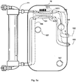
- Fig. 1a and Fig. 1b show the use of a cassette 10 for delivering dialysate streams 105, 106 in a dialysis apparatus according to one embodiment of the present invention. It's in terms of Fig. 1a and 1b It should be noted that the units, components or devices used in both Fig. 1a as well as in Fig. 1b have the same reference numerals, in both embodiments correspond to the same units, components or devices.
- the dialysis machine is in Fig. 1a and in Fig. 1b not shown, but for example as in Fig. 7 be designed indicated.
- the dialysis machine has receiving means which can receive the cassette 10.
- the cassette 10, according to the present embodiment, two centering units 107, by means of which the cassette 10 is locked in the dialysis device in the desired position, can be used.
- the centerings 107 can be introduced, for example, as guide holes for protruding from the dialysis device pins.
- the present invention also allows the use of further means for inserting the cassette 10 in the dialysis machine and is not limited to the centering units 107.
- Cartridges for delivering dialysate streams are well known.
- a conventional cassette is for example in the patent application DE 102 24 750 described.
- FIG. 1a and in Fig. 1b shown representations of the cassette 10 are directed essentially to the necessary for the present embodiment parts cassette. Therefore, other devices, units, or parts of a dialysis circuit (eg, sensors, actuators, etc.) that may be commonly found in the cartridge 10 are shown in FIG Fig. 1a and in Fig. 1b not shown, but may be included in the cassette 10 according to the present embodiment.
- a dialysis circuit eg, sensors, actuators, etc.
- the cassette 10 has according to Fig. 1a and 1b a dialysate input 102 from a fresh dialysate source and a dialysate output 103.
- the cassette 10 For pumping the dialysate stream 105, the cassette 10 according to the present embodiment has a dialysate pump 104.
- the delivery rate of dialysate pump 104 determines the level of dialysate flow rate.
- the cassette 10 may further comprise an ultrafiltration pump 108 which may remove dialysate from the dialysis filter 11 downstream of the dialysis filter 11.
- the dialysate flow 105 flows from the fresh dialysate source into the inlet 102 via the sensor 101, which is designed for balancing liquid flows, to the dialysis filter 11.
- a mass transfer between the patient's blood and dialysate takes place via the semipermeable membrane of the dialysis filter 11, as a result the patient's blood is cleansed of toxins.
- a difference in pressure between the dialysate side and the blood side of the semipermeable membrane allows liquid to be filtered across the membrane from the blood into the dialysate to dehydrate the patient.
- the volume of the liquid filtered from the patient's blood to the dialysate side per unit of time is called the ultrafiltration rate and is prescribed individually by the attending physician.
- the dialysate stream 106 which flows out of the dialysate filter 11 is greater than the dialysate stream 105, which flows into the dialysis filter 11. Since the difference of the two streams 105, 106 can only come from the patient's blood, the difference is equivalent to the ultrafiltration rate.
- the ultrafiltration rate depends primarily on the pressure difference between the blood and dialysate side in the dialysis filter 11. It is true that the more liquid is filtered from the blood to the dialysate side, the higher the pressure surplus on the blood side. The resulting pressure on both sides of the semipermeable membrane is proportional to the delivery side of the blood and the dialysate.
- the ultrafiltration rate can be regulated.
- a control of the blood pump (in Fig. 1a and 1b not shown) or the blood and the dialysate pump is also conceivable.
- the transmembrane pressure can also be generated with the ultrafiltration pump 108 (see Fig. 1b ).
- This additionally draws dialysate 106 downstream of the dialysis filter 11 from the Dialysis filter off. This can be done continuously or periodically. Occluding upstream of the dialyzer, the dialysate is promoted, for example, by the design of the dialysate pump 104 as a hose reel pump, the volume additionally removed from the ultrafiltration pump 108 from the dialysis filter 11 must come from the blood via the semipermeable membrane of the dialysis filter 11 and thus represents the ultrafiltrate. The ultrafiltration can be done continuously in this case.
- dialysate upstream of the filter 11 dialysate is not promoted, for example by designing the dialysate pump 11 as a centrifugal pump, additional occluding means must be provided upstream of the filter 11 (eg pinch valves, not in Fig. 1b shown) occluding the dialysate fluid system during delivery of the ultrafiltration pump 108.
- additional occluding means must be provided upstream of the filter 11 (eg pinch valves, not in Fig. 1b shown) occluding the dialysate fluid system during delivery of the ultrafiltration pump 108.
- the volume additionally removed by the ultrafiltration pump 108 must originate from the blood via the semipermeable membrane of the dialysis filter 11 and thus represents the ultrafiltrate.
- the ultrafiltration then takes place periodically.
- the dialysis pump 104 and the ultrafiltration pump 108 then operate alternately.
- the additional volume of liquid which is the ultrafiltrate, flows over the sensor 101 and the channel 1012.
- the ultrafiltration volume is known.
- the sensor signals of the sensor 101 can then be used in this embodiment also in this embodiment to adjust the delivery rate of the ultrafiltration pump 108 so that the desired ultrafiltration rate is established.
- the sensor 10 has a first channel 1011 for flowing the blood or dialysate stream 105 coming from the patient and a second channel 1012 for flowing the blood or dialysate stream 106 which flows to the patient after filtering.
- first and second are not to be construed as limiting in this description and merely serve to better distinguish the two channels 1011, 1012 of the sensor 10.
- the two channels 1011, 1012 are configured substantially parallel to one another. They may be arranged one above the other or side by side, the present invention has no limitations in this respect.
- the blood or dialysate streams 105, 106 flow in the sensor 101 according to the present embodiment in countercurrent to each other over.
- the present invention is not limited to the counterflow direction of the streams 105, 106.
- the liquid streams 105, 106 may also flow in the same direction.
- Another embodiment, analogous to the embodiment of the Fig. 1 is realized by using the sensor 101 to balance blood.
- This difference can also be detected by the sensor 101.
- This embodiment can analogously to the embodiment in Fig. 1 be configured, with the difference that now blood at the inlet 102 via the first channel 1011 of the sensor 101 flows. From there, blood is delivered through the lower blood inlet of the dialysis filter through the filter and from the upper blood outlet of the filter through the second channel 1012 of the sensor.
- the sensor 101 detects the voltages resulting from the flow of the blood or dialysate stream 105 in the channel 1011 and from the flow of the blood or dialysate stream 106 in the channel 1012.
- the detection of the voltages will become more specific with respect to the embodiment of FIG Fig. 2 be explained.
- the voltages are detected in the sensor 101 by means of corresponding voltage measuring units, which may be electrodes, for example.
- the use of stress measuring units in this context is generally known and therefore not explained in detail, see, for example, the patent application GB 2 003 274 A in which the insertion of electrodes is disclosed. Any suitable known tension measuring units may be used in accordance with the present invention.
- the sensor 101 is configured to transmit or transmit the sensed or measured voltages of the blood or dialysate streams 105, 106 in the channels 1011, 1012 to the dialysis machine.
- the sensor 101 has four voltage measuring units included in Fig. 1 not shown, two of which are attached to one of the channels 1011, 1012, respectively.
- the number of tension measuring units used can vary and is not limited to the use of four tension measuring units.
- electrodes are used as voltage measuring units.
- the sensor 101 has at least one transmission unit. According to the present embodiment, this transmission unit is a contact. Further, according to the present embodiment four transmission units 1013 used as contacts.
- the number of transmission units 1013 used may vary and is not limited to the use of four transmission units 1013. According to the present embodiment, the number of the transmission units 1013 corresponds to the number of the voltage measuring units. In this case, each electrode which is used as a voltage measuring unit is assigned to a transmission unit or a contact 1013.
- the contacts 1013 are the contacts of the four electrodes.
- the contacts 1013 are guided out of the sensor 101 on one side of the sensor 101 and are conductively connected to the dialysis device according to the present embodiment. By means of these contacts 1013, the sensor 101 transmits the determined or measured voltage values of the dialysis device, which can read the voltage values from the contacts 1013.
- the voltage values of the channels 1011, 1012 are used to balance the blood or dialysate streams 105, 106. This will be explained in more detail with reference to FIG. 8.
- contacts 1013 as transmitting units 1013.
- an inductance designed as a receiver coil, generating energy in the cassette by induction from an alternating magnetic field, which provides the dialysis machine or device, and provide in a known manner by rectifying the AC voltage to the receiving coil of an integrated electronic voltage in the cassette.
- This electronic circuit may be configured to process the voltage values of the voltage measuring units of the sensor 101 and to generate therefrom a signal which is contactless, e.g. transmitted via radio or load modulation of the receiver coil to the dialysis machine or device.
- Fig. 2 shows a device 101 for balancing a first and a second liquid flow according to an embodiment.
- the device 101 according to the present embodiment corresponds to the in Fig. 1 shown sensor 101 and shows a detailed embodiment of the sensor 101st
- the sensor 101 has a measuring cell 21, which is set up inside the sensor 101.
- the measuring cell 21 comprises or points to the channel 1011 and the channel 1012.
- the channels 1011, 1012 exemplified as a cuboid. It is to be noted, however, that the present invention is not limited to parallelepiped channels, the present invention is also applicable to other forms usable for channels, eg, cylindrical channels, etc.
- the two channels 1011, 1012 are the same or identical , They are designed the same or identical in particular with regard to their shape, size and dimensions.
- the measuring cell 21 of the sensor 101 is constructed or designed such that the two streams 105, 106 flow past each other in two separate channels 1011, 1012 in countercurrent flow. If the measuring cell 21 is introduced in the sensor 101 into a magnetic field which is directed perpendicular to the flow direction of the blood or dialysate streams 105, 106 or to the channels 1011, 1012 respectively, a charge separation of the positive and negative charge carriers in the fluid occurs.
- the driving force is the Lorentz force.
- the orientation of the magnetic field perpendicular to the blood or dialysate streams 105, 106 or to the channels 1011, 1012 is in FIG Fig. 2 illustrated by the arrow 20.
- the voltage generated by the charge application in the channels 1011, 1012 is measured.
- the potential difference depends on the distance or on the strength of the magnetic field.
- the conductivity of the medium in the sensor 101 does not play a decisive role.
- a minimum conductivity should be given.
- U B * v * D .
- the flowing blood or dialysate, respectively, in the channel 1011 also creates a voltage as the blood or dialysate in the channel 1012. If the blood or dialysate from the channel 1011 after exiting the measuring cell 21 again flow directly into the entrance of the channel 1012, so would the induced voltages cancel each other exactly. That is, a difference of the voltage of the first channel 1011 and the voltage of the second channel 1012 would be zero. If a difference between the two voltages results in a value not equal to zero, the volume flow in both channels 1011, 1012 must be unequal.
- the ultrafiltration rate a rate formed from differences in the voltages of the channels 1011, 1012 is referred to as the ultrafiltration rate.
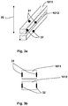
- FIGS. 3a and 3b show a detailed view of the channels 1011, 1012 according to one embodiment.
- each of the first channel 1011 and the second channel 1012 has voltage measuring units for measuring the voltages in the channels 1011, 1012, which are generated by the charge separation as described above and caused by the flow of the respective liquid streams 105, 106.
- the tension measuring units 31, 32 are electrodes.
- each channel 1011, 1012 on two opposite sides of the respective channels 1011, 1012 each have an electrode 31, 32.
- the electrodes 31, 32 are arranged parallel to the orientation 20 of the magnetic field.
- Fig. 3a and Fig. 3b merely show an exemplary embodiment of the present invention.
- the difference of the two measured voltage values is formed for balancing the blood or dialysis currents 105, 106 according to formula (2).
- the exciting magnetic field B can be both a non-variable magnetic field and an alternating magnetic field.
- the self-adjusting voltages are direct voltages in the case of a stimulating non-variable magnetic field, alternating voltages in the case of a stimulating alternating magnetic field. In both cases, the current amplitude of the resulting voltage is modulated by the current fluid flow.
- the difference in the voltage values is carried out in a manner known to the person skilled in the art, e.g. via an analog subtraction circuit or by digitizing the measured values and subsequent mathematical operations in a computing device provided for this, which may be part of a control device of the dialysis machine or device.
- Fig. 4a, 4b show in a device for balancing a first and a second liquid flow established channels 41, 42 for a first and a second liquid, blood or dialysate stream according to two other embodiments.
- each of the channels 41, 42 has a voltage measuring unit 411, 421.
- the tension measuring units 411, 421 are electrodes and are arranged on the opposite outer walls of the channels 41, 42, the outer walls being the outer walls oriented parallel to the orientation 20 of the magnetic field.
- each electrode 411, 421 directly supplies the voltage value of the respective channel 41, 42.
- the two channels 41, 42 are separated by a partition 40, which as in relation to Fig. 4a is set up.
- the channels 41, 42 have a total of three voltage measuring units 411, 421, 43 as electrodes.
- the embodiment of Fig. 4b represents an extension of the embodiment of Fig. 4a wherein a common voltage measuring unit 43 as Electrode for measuring the voltage in both channels 41, 42 is arranged in the partition wall 43 between the electrodes 411, 421 at the same height to the electrodes 411, 421. Similar to the embodiment of Fig. 3a and the Fig.
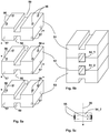
- Fig. 5a and Fig. 5b show an arrangement having two channels 54_1, 54_2 for two liquid, blood or dialysate streams, and the structure of the arrangement according to an embodiment.
- the measuring cell 21 is preferably made of symmetrical parts 51, 52, 53.
- the parts 51, 52, 53 are made of the same or a single injection molding tool.
- the three parts 51, 52, 53 are the same in shape and dimension.
- the parts 51, 52, 53 are substantially cuboid.
- each of the parts 51, 52, 53 has a liquid passage 50 on two opposite sides.
- the three parts 51, 52, 53 are assembled according to the present embodiment by a series of the provided with a liquid flow 50 sides.
- the knobs 56 and the recesses 57 are formed by way of example substantially as a cuboid.
- Fig. 5b shows the finished, created from the parts 51, 52, 53 arrangement, which has two equal, mutually parallel and superimposed channels 54_1, 54_2.
- each part 51, 52, 53 may have a typical mechanical error, it is important, by skillful combination of the channels, each having an upper part-channel of the upper part 51, 52 and a lower part-channel of the corresponding lower Part 52, 53 to assemble a total channel 54_1, 54_2. Small depressions or elevations can provide the appropriate positioning. Even if the positioning of the parts 51, 52, 53 is not exact, that is, if the respective upper and lower channel halves are not exactly on top of each other, the two total channels 54_1, 54_2 are identical.
- the liquid flows 50 have a substantially cuboidal shape, which also leads to a cuboidal configuration of the total channels 54_1, 54_2. It should be noted that this configuration of the liquid flows 50 and the channels 54_1, 54_2 is exemplary and that according to the present invention, further suitable shapes of the liquid flows 50 and consequently of the channels 54_1, 54_2 are possible.
- Fig. 6a and Fig. 6b show an arrangement having two channels for two liquid, blood or Dialysatströme, and the structure of the arrangement according to a further embodiment.
- Fig. 6a and Fig. 6b corresponds to the embodiment of Fig. 5a and the Fig. 5b ,
- the difference between the two embodiments is that according to Fig. 6a and Fig. 6b the parts 61, 62, 63 each have only one liquid run 60 on one side.
- the assembly of the arrangement according to Fig. 6a and Fig. 6b from the parts 61, 62, 63 is similar to the assembly of the parts 51, 52, 53 in Fig. 5a 5b , According to the In the present exemplary embodiment, a side of a part 62, 63 configured with a liquid run 60 is assembled with a side of a part 61, 62 which is not designed with a liquid run 60.
- Fig. 6b illustrates the resulting from the assembly of the parts 61, 62, 63 channels 64_1, 64_2.
- the advantage of this embodiment is that it does not require 100% positioning of the parts 61, 62, 63 and that slight deviations are possible since there is no extremely careful alignment of an upper part of the channel 54_1, 54_2 with the lower part of the channel 54_1 , 54_2 is needed.
- the knobs 66 and depressions 67 of the present embodiment are substantially formed as a cuboid.
- the present invention is not limited to the cuboid shape of the dimples 66 and recesses 67 as shown, and that it also allows for further suitable formations of the dimples 66 and recesses 66, and that according to the present invention, other suitable fastening units are also used can be.
- the magnetic field can be oriented perpendicular to the stacked parts 51, 52, 53 and 61, 62, 63.
- Fig. 5c a dc field situation has been created by the action of the magnetic field.
- the exemplified channel 54_2 has two electrodes 55 as voltage measuring units.
- the left-side electrode 55 is configured to measure the negative-carrier voltage
- the right-side electrode 55 is configured to measure the positive-carrier voltage.
- the charge separation of the positive and negative charge carriers is produced by the magnetic field acting perpendicularly on the channel 54_2 in the measuring cell 21 or in the sensor 101, respectively.
- a sensor signal (derived, for example, from the sensor 101) may be used as a measure of the differential flow between dialysate (ie, blood or dialysate 105 from the patient) and dialysate (ie, blood or dialysate 106) flowing into a dialyzer to the patient) can be used to control the flow of the dialysate pump.
- more than inflow means that fluid from the patient's blood has entered the dialysate via the semipermeable membrane of the dialysis filter.
- This liquid per unit time corresponds to the ultrafiltration rate.
- the ultrafiltration rate is prescribed by the doctor. If the sensor signal is now fed to a control or regulation unit which controls the pump flow (ie the settings of the blood or dialysate pump) depending on the actual value of the difference flow (difference between the voltages of the channels of the sensor), the ultrafiltration rate can be regulated ,
- the ultrafiltration rate is dependent on the transmembrane pressure, which depends essentially on the blood or dialysate flow 105 from the patient and the blood or dialysate flow 106 to the patient, as well as the properties of the dialyzer (e.g., HighFlux property).
- the pump capacity of either the dialysate pump and / or the blood pump can be adjusted so that the desired ultrafiltration rate is established.
- a lower blood or dialysate flow 106 to the patient may mean a higher transmembrane pressure from the side of the flow 105 from the patient to the side of the flow 106 to the patient, thus allowing more fluid from the side of the flow 105 from the patient to the side of the flow 106 to the patient is filtered.
- the reverse case means refiltration, which is usually undesirable.
- Fig. 7 shows a dialysis machine 7, which is configured or configured according to an embodiment for dialysis treatment.
- the dialysis device 7 has a receiving unit 71, which is configured to receive at least one cassette for conveying blood or dialysate streams 105, 106.
- the cassette is at in relation to the Fig. 1 described cassette 10.
- the parts, units and / or components of the dialysis apparatus 7 that are relevant for the present exemplary embodiment are essentially shown.
- the dialysis device 7 also includes other conventional manner contained in dialysis devices parts, units and / or components that allow the proper functioning of the dialysis machine 7.
- Fig. 7 For the sake of clarity, these conventional parts, units and / or components of a dialysis machine are in Fig. 7 Not shown.
- the cassette 10 the sensor 101 for balancing the blood or Dialysatstroms 105 from the patient and the blood or Dialysatstroms 106 to the patient, the two streams 105, 106 parallel to each other and according to the present embodiment in opposite directions in the respective channels 1011, 1012 of the sensor 101 flow (the streams 105, 106 may also flow in the same direction).
- the dialysis apparatus 7 is configured or configured to detect a signal having a difference in the voltage detected in the channel 1011 and the voltage detected in the channel 1012.
- the respective stresses arise from a perpendicular alignment 20 of a magnetic field on the channels 1011, 1012 in the sensor 101 and by the flow of the respective blood or dialysate streams 105, 106 in the channels 1011, 1012.
- the perpendicular alignment of the magnetic field represents only an exemplary alignment of the magnetic field and that, according to the present invention, other angles can also be used in aligning the magnetic field.
- the sensor 101 has corresponding voltage measuring units configured to measure the respective voltages in the channels 1011, 1012.
- the dialysis machine 8 is configured to detect the voltage values measured by the voltage measuring units. So for example this can be done by means of in Fig. 1 illustrated transmission units 1013, which may be as shown above contacts, coils or other means.
- the dialysis device 7 determines the corresponding voltage value for each channel 1011, 1012 in accordance with the present exemplary embodiment. If several voltage values for a channel 1011, 1012 have been measured by a plurality of voltage measuring units, mean value calculations can be used for this, for example. Such calculations for determining a general, representative voltage value from a plurality of measured voltage values are familiar to the expert, therefore, will not be discussed in more detail here on such calculations.
- the dialysis apparatus 7 uses the voltage value detected for the first channel 1011 and the voltage value detected for the second channel 1012 to calculate a difference of the voltages or voltage values of the two channels 1011, 1012. As already stated, this difference corresponds to the ultrafiltration rate.
- the dialysis device 7 has a control or regulating unit 72, which is designed, by means of the determined difference between the voltages of the first and second channels 1011, 1012 of the sensor 101, to flow at least one of the blood or dialysate flows 105, 106 to control or regulate.
- This can be done by the control unit 72, for example, by a corresponding setting of the blood and / or Dialysatpumpe when the control unit 72 has received the current difference of the voltages and after the evaluation of the difference has determined that the difference is not the (from the doctor) predetermined ultrafiltration rate corresponds.
- Controlling or regulating at least one of the blood or dialysate streams 105, 106 is performed by the control unit 72 such that the current ultrafiltration rate or difference in voltages in the channels 1011, 1012 after being controlled by the control unit 72 of the predetermined ultrafiltration rate or difference of the voltages in the channels 1011, 1012 corresponds, for example can be effected by a corresponding adjustment of the blood and / or Dialysatpumpe.
- the dialysis device 7 is designed to detect the difference between the actual voltages of the channels 1011, 1012 or the current ultrafiltration rate, a signal 73 which has the difference between the actual voltages of the channels 1011, 1012 and the current ultrafiltration rate, to transmit to the control unit 72. If the difference between the current voltages of the channels 1011, 1012 or the current ultrafiltration rate does not correspond to the difference (defined by the physician) of the current voltages of the channels 1011, 1012 or the predetermined ultrafiltration rate, the control unit 72 controls or regulates the Blood or dialysate streams 105, 106 as described above.
- the present invention relates to balancing fluid flows in a dialysis system.
- a cassette for conveying a first and a second Liquid stream in a dialysis system wherein the first and the second liquid stream medical medicinal streams such as Dialysatströme or blood streams may be
- the cassette has a sensor as a device for balancing the first and second liquid stream and wherein the sensor has a first channel for the first liquid stream and a second channel for the second liquid stream.
- a dialysis apparatus configured to receive at least one cassette configured as set forth above and an arrangement are provided by which two channels are formed for the first and second liquid streams.
- a method of constructing the two channels or the arrangement is proposed.
- the channels of the sensor or the flows of the parts to construct a two-channel array may have different shapes, or different calculation methods may be used to determine a representative channel voltage using various voltages or voltages measured for the channel, respectively.
Landscapes
- Health & Medical Sciences (AREA)
- Heart & Thoracic Surgery (AREA)
- Vascular Medicine (AREA)
- Engineering & Computer Science (AREA)
- Public Health (AREA)
- Biomedical Technology (AREA)
- Hematology (AREA)
- Life Sciences & Earth Sciences (AREA)
- Animal Behavior & Ethology (AREA)
- General Health & Medical Sciences (AREA)
- Anesthesiology (AREA)
- Veterinary Medicine (AREA)
- Urology & Nephrology (AREA)
- Emergency Medicine (AREA)
- Physics & Mathematics (AREA)
- Cardiology (AREA)
- Fluid Mechanics (AREA)
- Electromagnetism (AREA)
- General Physics & Mathematics (AREA)
- Mechanical Engineering (AREA)
- General Engineering & Computer Science (AREA)
- External Artificial Organs (AREA)
Applications Claiming Priority (4)
| Application Number | Priority Date | Filing Date | Title |
|---|---|---|---|
| DE102010002871 | 2010-03-15 | ||
| DE102010003642A DE102010003642A1 (de) | 2010-03-15 | 2010-04-01 | Kassette mit einem Sensor zur Bestimmung der Differenz eines ersten und eines zweiten Flüssigkeitsstroms |
| PCT/EP2011/053907 WO2011113838A1 (fr) | 2010-03-15 | 2011-03-15 | Cassette pourvue d'un détecteur pour déterminer la différence d'un premier et d'un deuxième flux de liquide |
| EP11708845.0A EP2547378B1 (fr) | 2010-03-15 | 2011-03-15 | Cassette pourvue d'un détecteur pour déterminer la différence d'un premier et d'un deuxième flux de liquide |
Related Parent Applications (2)
| Application Number | Title | Priority Date | Filing Date |
|---|---|---|---|
| EP11708845.0A Division EP2547378B1 (fr) | 2010-03-15 | 2011-03-15 | Cassette pourvue d'un détecteur pour déterminer la différence d'un premier et d'un deuxième flux de liquide |
| EP11708845.0A Division-Into EP2547378B1 (fr) | 2010-03-15 | 2011-03-15 | Cassette pourvue d'un détecteur pour déterminer la différence d'un premier et d'un deuxième flux de liquide |
Publications (1)
| Publication Number | Publication Date |
|---|---|
| EP3372261A1 true EP3372261A1 (fr) | 2018-09-12 |
Family
ID=44507710
Family Applications (2)
| Application Number | Title | Priority Date | Filing Date |
|---|---|---|---|
| EP11708845.0A Active EP2547378B1 (fr) | 2010-03-15 | 2011-03-15 | Cassette pourvue d'un détecteur pour déterminer la différence d'un premier et d'un deuxième flux de liquide |
| EP18163445.2A Withdrawn EP3372261A1 (fr) | 2010-03-15 | 2011-03-15 | Dispositif de commande/réglage d'un taux d'ultrafiltration dans un dispositif de dialyse à l'aide d'une différence déterminée d'un premier et d'un deuxième flux de liquide |
Family Applications Before (1)
| Application Number | Title | Priority Date | Filing Date |
|---|---|---|---|
| EP11708845.0A Active EP2547378B1 (fr) | 2010-03-15 | 2011-03-15 | Cassette pourvue d'un détecteur pour déterminer la différence d'un premier et d'un deuxième flux de liquide |
Country Status (6)
| Country | Link |
|---|---|
| US (3) | US9399089B2 (fr) |
| EP (2) | EP2547378B1 (fr) |
| JP (1) | JP5878487B2 (fr) |
| CN (1) | CN102844057B (fr) |
| DE (1) | DE102010003642A1 (fr) |
| WO (1) | WO2011113838A1 (fr) |
Families Citing this family (44)
| Publication number | Priority date | Publication date | Assignee | Title |
|---|---|---|---|---|
| US7736328B2 (en) | 2007-07-05 | 2010-06-15 | Baxter International Inc. | Dialysis system having supply container autoconnection |
| US10089443B2 (en) | 2012-05-15 | 2018-10-02 | Baxter International Inc. | Home medical device systems and methods for therapy prescription and tracking, servicing and inventory |
| DE102010038923A1 (de) * | 2010-08-04 | 2012-02-09 | Robert Bosch Gmbh | Dialyse-Kassette zur Heimhämodialyse |
| CN103889481B (zh) | 2011-08-02 | 2016-03-09 | 美敦力公司 | 带有具有可控的顺应性容积的流动路径的血液透析系统 |
| DE102011114506A1 (de) * | 2011-09-22 | 2013-03-28 | Technische Universität Ilmenau | Verfahren und Vorrichtung zur berührungslosen Messung eines Massen- oder Volumenstromes eines elektrisch leitfähigen Fluids |
| CN102631720A (zh) * | 2012-04-28 | 2012-08-15 | 广东宝莱特医用科技股份有限公司 | 一种带有检测功能的平衡腔 |
| US9713666B2 (en) | 2013-01-09 | 2017-07-25 | Medtronic, Inc. | Recirculating dialysate fluid circuit for blood measurement |
| US11154648B2 (en) | 2013-01-09 | 2021-10-26 | Medtronic, Inc. | Fluid circuits for sorbent cartridge with sensors |
| ITBO20130024A1 (it) * | 2013-01-21 | 2014-07-22 | Medica S P A | Flussimetro differenziale per la misura del calo ponderale in trattamenti di emodialisi |
| DE102013001587A1 (de) * | 2013-01-30 | 2014-07-31 | Fresenius Medical Care Deutschland Gmbh | Vorrichtung und Verfahren zur Regelung einer Behandlungsvorrichtung |
| US10850016B2 (en) | 2013-02-01 | 2020-12-01 | Medtronic, Inc. | Modular fluid therapy system having jumpered flow paths and systems and methods for cleaning and disinfection |
| US10010663B2 (en) | 2013-02-01 | 2018-07-03 | Medtronic, Inc. | Fluid circuit for delivery of renal replacement therapies |
| US9623164B2 (en) | 2013-02-01 | 2017-04-18 | Medtronic, Inc. | Systems and methods for multifunctional volumetric fluid control |
| DE102013002395A1 (de) * | 2013-02-13 | 2014-08-14 | Fresenius Medical Care Deutschland Gmbh | Vorrichtung und Verfahren zur Regelung einer Behandlungsvorrichtung |
| DE102013006142A1 (de) * | 2013-04-10 | 2014-10-16 | Fresenius Medical Care Deutschland Gmbh | Vorrichtung zum Messen eines Flüssigkeitsflusses |
| US10537875B2 (en) | 2013-11-26 | 2020-01-21 | Medtronic, Inc. | Precision recharging of sorbent materials using patient and session data |
| US9884145B2 (en) | 2013-11-26 | 2018-02-06 | Medtronic, Inc. | Parallel modules for in-line recharging of sorbents using alternate duty cycles |
| DE102014103492A1 (de) * | 2014-03-14 | 2015-09-17 | Fresenius Medical Care Deutschland Gmbh | Flüssigkeitskassette mit kipptoleranter Zentrierverrastung sowie Blutbehandlungsvorrichtung |
| WO2015156299A1 (fr) * | 2014-04-07 | 2015-10-15 | キョーラク株式会社 | Article moulé creux |
| JP6347139B2 (ja) * | 2014-04-07 | 2018-06-27 | キョーラク株式会社 | 中空成形品 |
| US10357757B2 (en) | 2014-06-24 | 2019-07-23 | Medtronic, Inc. | Stacked sorbent assembly |
| EP3160535B1 (fr) | 2014-06-24 | 2024-10-02 | Mozarc Medical US LLC | Ensemble de régénération de dialysat modulaire |
| DE102014009444A1 (de) * | 2014-06-25 | 2015-12-31 | Fresenius Medical Care Deutschland Gmbh | Flussmesser und Kassettenmodul für einen Flussmesser |
| US10980929B2 (en) | 2014-09-12 | 2021-04-20 | Diality Inc. | Hemodialysis system with ultrafiltration controller |
| US10016550B2 (en) | 2014-09-12 | 2018-07-10 | Easydial, Inc. | Portable hemodialysis assembly with ammonia sensor |
| JP6395568B2 (ja) * | 2014-11-13 | 2018-09-26 | 愛知時計電機株式会社 | 流量計測器及び電磁流量計 |
| DE102015001406B3 (de) * | 2015-02-04 | 2016-07-14 | Fresenius Medical Care Deutschland Gmbh | Kassettenmodul für einen Differenzflussmesser und Differenzflussmesser |
| DE102015104431A1 (de) * | 2015-03-24 | 2016-09-29 | Fresenius Medical Care Deutschland Gmbh | Bilanzierungsverfahren und temperaturstörungsunabhängige Bilanzierungseinrichtung |
| DE102015104430A1 (de) * | 2015-03-24 | 2016-09-29 | Fresenius Medical Care Deutschland Gmbh | Temperaturstörungsunabhängige Bilanzierungseinrichtung und Bilanzierungsverfahren |
| JP6524832B2 (ja) * | 2015-07-16 | 2019-06-05 | キョーラク株式会社 | 中空成形体 |
| WO2017193065A1 (fr) | 2016-05-06 | 2017-11-09 | Gambro Lundia Ab | Systèmes et procédés de dialyse péritonéale ayant une préparation de fluide de dialyse au point d'utilisation comprenant un test de cette dernière |
| US10981148B2 (en) | 2016-11-29 | 2021-04-20 | Medtronic, Inc. | Zirconium oxide module conditioning |
| DE102017106403A1 (de) | 2017-03-24 | 2018-09-27 | Fresenius Medical Care Deutschland Gmbh | Medizinische Einrichtung mit additiv aufgebrachtem Wandler samt Leiterbahn |
| DE102017106402A1 (de) | 2017-03-24 | 2018-09-27 | Fresenius Medical Care Deutschland Gmbh | Medizinische Einrichtung mit additiv aufgebrachtem Wandler |
| US10960381B2 (en) | 2017-06-15 | 2021-03-30 | Medtronic, Inc. | Zirconium phosphate disinfection recharging and conditioning |
| DE102018101568A1 (de) * | 2018-01-24 | 2019-07-25 | Krohne Ag | Magnetisch-induktives Durchflussmessgerät |
| US12285552B2 (en) | 2018-08-14 | 2025-04-29 | Mozarc Medical Us Llc | Precision dialysis therapy based on sorbent effluent analysis |
| US11213616B2 (en) | 2018-08-24 | 2022-01-04 | Medtronic, Inc. | Recharge solution for zirconium phosphate |
| US10967719B1 (en) | 2019-11-11 | 2021-04-06 | SinchTech Covers, LLC | Vehicle cover and integrated security system |
| DE102020102485A1 (de) * | 2020-01-31 | 2021-08-05 | Fresenius Medical Care Deutschland Gmbh | Flusssensor und Verfahren zum Messen eines Flusses |
| CN111652849B (zh) * | 2020-05-08 | 2022-03-01 | 武汉联影医疗科技有限公司 | 血流参数计算结果获取方法、装置、设备和系统 |
| US12569601B2 (en) | 2021-04-07 | 2026-03-10 | Mozarc Medical Us Llc | Increased operational capabilities of a dialysis system |
| US12397093B2 (en) | 2021-05-18 | 2025-08-26 | Mozarc Medical Us Llc | Sorbent cartridge designs |
| US20240216596A1 (en) | 2022-12-22 | 2024-07-04 | Fresenius Medical Care Deutschland Gmbh | Medical Functional Device for Hemodialysis, Balancing Device and Method |
Citations (9)
| Publication number | Priority date | Publication date | Assignee | Title |
|---|---|---|---|---|
| GB2003274A (en) | 1977-07-12 | 1979-03-07 | Repgreen Ltd | Compensating for fluid channel dimension variations in a flowmeter |
| EP0122604A1 (fr) * | 1983-04-13 | 1984-10-24 | Fresenius AG | Appareil de régulation du débit d'ultrafiltration |
| JPH05329205A (ja) * | 1991-10-01 | 1993-12-14 | Fumio Watanabe | 人工透析装置 |
| DE10313685A1 (de) * | 2002-03-26 | 2003-10-09 | Peter Prechtl | Mikroreaktor |
| DE10224750A1 (de) | 2002-06-04 | 2003-12-24 | Fresenius Medical Care De Gmbh | Vorrichtung zur Behandlung einer medizinischen Flüssigkeit |
| US20090032232A1 (en) * | 2006-03-22 | 2009-02-05 | Matsushita Electric Industrial Co., Ltd. | Heat exchanger and its manufacturing method |
| US20090095679A1 (en) * | 2007-02-27 | 2009-04-16 | Deka Products Limited Partnership | Hemodialysis systems and methods |
| US20090101550A1 (en) * | 2007-10-22 | 2009-04-23 | Baxter International Inc. | Dialysis system having non-invasive fluid velocity sensing |
| DE202008012801U1 (de) * | 2008-09-26 | 2010-03-04 | Gebr. Kemper Gmbh + Co. Kg | Messarmatur |
Family Cites Families (43)
| Publication number | Priority date | Publication date | Assignee | Title |
|---|---|---|---|---|
| US3522527A (en) | 1967-09-13 | 1970-08-04 | British Iron Steel Research | Method and apparatus for measuring material thickness |
| JPS4915228Y1 (fr) | 1969-05-16 | 1974-04-16 | ||
| BE757310A (fr) | 1969-10-11 | 1971-04-09 | Siemens Ag | Procede pour la determination de la difference volumetrique de deux courants de matiere par la mesure inductive du debit |
| US3946731A (en) * | 1971-01-20 | 1976-03-30 | Lichtenstein Eric Stefan | Apparatus for extracorporeal treatment of blood |
| JPS517941B2 (fr) | 1972-06-03 | 1976-03-12 | ||
| JPS5244214A (en) | 1975-10-03 | 1977-04-07 | Matsushita Electric Works Ltd | Method of producing thin woody veneer laminated board |
| JPS5434268A (en) * | 1977-07-12 | 1979-03-13 | Repgreen Ltd | Method of and apparatus for correcting high channel mismatching in differential type flow rate measurement |
| US4211987A (en) | 1977-11-30 | 1980-07-08 | Harris Corporation | Cavity excitation utilizing microstrip, strip, or slot line |
| SE434192B (sv) * | 1982-09-28 | 1984-07-09 | Gambro Lundia Ab | Anordning for metning av skillnaden mellan tva floden i tva skilda kanaler |
| JPH01170826A (ja) * | 1987-12-25 | 1989-07-05 | Sumitomo Electric Ind Ltd | 液体の漏洩検出方法 |
| US5644240A (en) * | 1992-09-30 | 1997-07-01 | Cobe Laboratories, Inc. | Differential conductivity hemodynamic monitor |
| US5417119A (en) * | 1994-01-07 | 1995-05-23 | Smoll; Owen C. | Dual electromagnet partially disposable fluid flow transducer with side-by-side electrodes |
| JPH07336139A (ja) | 1994-06-07 | 1995-12-22 | Fujitsu Ltd | 発振器 |
| FR2723002B1 (fr) * | 1994-07-26 | 1996-09-06 | Hospal Ind | Dispositif et procede pour preparer un liquide de traitement par filtration |
| US6595943B1 (en) * | 1997-02-14 | 2003-07-22 | Nxstage Medical, Inc. | Systems and methods for controlling blood flow and waste fluid removal during hemofiltration |
| JPH10253411A (ja) * | 1997-03-06 | 1998-09-25 | Yokogawa Electric Corp | 低導電率電磁流量計 |
| US6331252B1 (en) * | 1998-07-31 | 2001-12-18 | Baxter International Inc. | Methods for priming a blood compartment of a hemodialyzer |
| US20020112961A1 (en) * | 1999-12-02 | 2002-08-22 | Nanostream, Inc. | Multi-layer microfluidic device fabrication |
| IT1320024B1 (it) * | 2000-04-07 | 2003-11-12 | Gambro Dasco Spa | Metodo per la regolazione della infusione in una macchina di dialisi e macchina di dialisi per l'applicazione del citato metodo. |
| US6561208B1 (en) * | 2000-04-14 | 2003-05-13 | Nanostream, Inc. | Fluidic impedances in microfluidic system |
| US20030132291A1 (en) | 2002-01-11 | 2003-07-17 | Metrologic Instruments, Inc. | Point of sale (POS) station having bar code reading system with integrated internet-enabled customer-kiosk terminal |
| WO2002005059A2 (fr) | 2000-07-07 | 2002-01-17 | Baxter International Inc. | Systeme, procede et appareil medicaux utilisant des dispositifs mem |
| US6890093B2 (en) * | 2000-08-07 | 2005-05-10 | Nanostream, Inc. | Multi-stream microfludic mixers |
| EP1309404A2 (fr) * | 2000-08-07 | 2003-05-14 | Nanostream, Inc. | Melangeur fluidique pour systeme microfluidique |
| US6536477B1 (en) * | 2000-10-12 | 2003-03-25 | Nanostream, Inc. | Fluidic couplers and modular microfluidic systems |
| US6827095B2 (en) * | 2000-10-12 | 2004-12-07 | Nanostream, Inc. | Modular microfluidic systems |
| AU2002213191B2 (en) * | 2000-10-12 | 2006-06-01 | Renal Solutions, Inc. | Devices and methods for body fluid flow control in extracorporeal fluid treatments |
| US6418968B1 (en) * | 2001-04-20 | 2002-07-16 | Nanostream, Inc. | Porous microfluidic valves |
| US20030101825A1 (en) * | 2001-11-30 | 2003-06-05 | Neubert William J. | Aspiration tube for use with flow meter control system |
| AU2003297060A1 (en) * | 2002-12-13 | 2004-07-09 | Massachusetts Institute Of Technology | Vibratory venous and arterial oximetry sensor |
| US7246530B2 (en) * | 2003-02-10 | 2007-07-24 | Gambro Lundia Ab | Flow sensor and method for measuring a flow rate component of a fluid containing electrically charged elements |
| US20050049539A1 (en) * | 2003-09-03 | 2005-03-03 | O'hara Gerald P. | Control system for driving fluids through an extracorporeal blood circuit |
| US7922667B2 (en) * | 2004-06-04 | 2011-04-12 | The Regents Of The University Of Michigan | Electromagnetic flow sensor device |
| JP2006238915A (ja) * | 2005-02-28 | 2006-09-14 | Terumo Corp | 腹膜透析装置およびその制御方法、並びに制御プログラム |
| JP4765706B2 (ja) * | 2006-03-22 | 2011-09-07 | パナソニック株式会社 | 熱交換器の製造方法 |
| EP2724736B1 (fr) * | 2006-04-14 | 2022-06-08 | DEKA Products Limited Partnership | Cassette à pompe enclose |
| FR2900067B1 (fr) | 2006-04-20 | 2008-07-18 | Commissariat Energie Atomique | Systeme d'echangeur de chaleur comportant des zones de circulation fluidique revetues de facon selective par un catalyseur de reaction chimique |
| CN100438932C (zh) * | 2006-04-28 | 2008-12-03 | 重庆山外山科技有限公司 | 血液净化用容量平衡及超滤装置 |
| US8366655B2 (en) * | 2007-02-27 | 2013-02-05 | Deka Products Limited Partnership | Peritoneal dialysis sensor apparatus systems, devices and methods |
| US8042563B2 (en) * | 2007-02-27 | 2011-10-25 | Deka Products Limited Partnership | Cassette system integrated apparatus |
| US8491184B2 (en) * | 2007-02-27 | 2013-07-23 | Deka Products Limited Partnership | Sensor apparatus systems, devices and methods |
| US9028691B2 (en) * | 2007-02-27 | 2015-05-12 | Deka Products Limited Partnership | Blood circuit assembly for a hemodialysis system |
| US8114276B2 (en) * | 2007-10-24 | 2012-02-14 | Baxter International Inc. | Personal hemodialysis system |
-
2010
- 2010-04-01 DE DE102010003642A patent/DE102010003642A1/de active Pending
-
2011
- 2011-03-15 EP EP11708845.0A patent/EP2547378B1/fr active Active
- 2011-03-15 JP JP2012557531A patent/JP5878487B2/ja active Active
- 2011-03-15 EP EP18163445.2A patent/EP3372261A1/fr not_active Withdrawn
- 2011-03-15 CN CN201180019069.3A patent/CN102844057B/zh active Active
- 2011-03-15 WO PCT/EP2011/053907 patent/WO2011113838A1/fr not_active Ceased
- 2011-03-15 US US13/634,656 patent/US9399089B2/en active Active
-
2016
- 2016-06-20 US US15/186,672 patent/US10260682B2/en active Active
-
2018
- 2018-06-25 US US16/017,236 patent/US11085588B2/en active Active
Patent Citations (9)
| Publication number | Priority date | Publication date | Assignee | Title |
|---|---|---|---|---|
| GB2003274A (en) | 1977-07-12 | 1979-03-07 | Repgreen Ltd | Compensating for fluid channel dimension variations in a flowmeter |
| EP0122604A1 (fr) * | 1983-04-13 | 1984-10-24 | Fresenius AG | Appareil de régulation du débit d'ultrafiltration |
| JPH05329205A (ja) * | 1991-10-01 | 1993-12-14 | Fumio Watanabe | 人工透析装置 |
| DE10313685A1 (de) * | 2002-03-26 | 2003-10-09 | Peter Prechtl | Mikroreaktor |
| DE10224750A1 (de) | 2002-06-04 | 2003-12-24 | Fresenius Medical Care De Gmbh | Vorrichtung zur Behandlung einer medizinischen Flüssigkeit |
| US20090032232A1 (en) * | 2006-03-22 | 2009-02-05 | Matsushita Electric Industrial Co., Ltd. | Heat exchanger and its manufacturing method |
| US20090095679A1 (en) * | 2007-02-27 | 2009-04-16 | Deka Products Limited Partnership | Hemodialysis systems and methods |
| US20090101550A1 (en) * | 2007-10-22 | 2009-04-23 | Baxter International Inc. | Dialysis system having non-invasive fluid velocity sensing |
| DE202008012801U1 (de) * | 2008-09-26 | 2010-03-04 | Gebr. Kemper Gmbh + Co. Kg | Messarmatur |
Also Published As
| Publication number | Publication date |
|---|---|
| DE102010003642A1 (de) | 2011-09-15 |
| WO2011113838A1 (fr) | 2011-09-22 |
| JP5878487B2 (ja) | 2016-03-08 |
| US9399089B2 (en) | 2016-07-26 |
| EP2547378A1 (fr) | 2013-01-23 |
| US20160341366A1 (en) | 2016-11-24 |
| US11085588B2 (en) | 2021-08-10 |
| US20130075314A1 (en) | 2013-03-28 |
| EP2547378B1 (fr) | 2019-08-14 |
| US20180313499A1 (en) | 2018-11-01 |
| US10260682B2 (en) | 2019-04-16 |
| JP2013521910A (ja) | 2013-06-13 |
| CN102844057B (zh) | 2015-09-30 |
| CN102844057A (zh) | 2012-12-26 |
Similar Documents
| Publication | Publication Date | Title |
|---|---|---|
| EP2547378B1 (fr) | Cassette pourvue d'un détecteur pour déterminer la différence d'un premier et d'un deuxième flux de liquide | |
| EP2956188B1 (fr) | Dispositif de régulation d'un dispositif de traitement | |
| EP2844314B1 (fr) | Dispositif d'établissement de bilan d'un appareil de dialyse, circulation extracorporelle et procédé d'établissement de bilans hydriques au moyen d'une cellule de mesure de débit | |
| EP2627368B1 (fr) | Procédé et dispositif pour mesurer et éliminer des variations du système dans un dispositif de traitement du sang | |
| DE60026530T2 (de) | Dialyseapparat | |
| DE19746367C2 (de) | Verfahren zur in-vivo-Bestimmung von Parametern der Hämodialyse und Vorrichtung zur Durchführung des Verfahrens | |
| EP1348457B1 (fr) | Méthode pour déterminer des paramètres de traitement utilisant un appareil d'hémofiltration et dispositif pour cela | |
| EP2416699B1 (fr) | Dispositif et procédé de mesure d'un composant sanguin dans le sang pour un dispositif extracorporel de traitement du sang | |
| EP1144024A2 (fr) | Procede pour determiner le volume de distribution d'un constituant sanguin pendant un traitement sanguin extracorporel et dispositif pour mettre en oeuvre ledit procede | |
| WO2016091366A1 (fr) | Machine de dialyse pour la surveillance de variations temporelles du hématocrite et/ou des valeurs d'hemoglobine | |
| EP2482868B1 (fr) | Dispositif de traitement par dialyse et procédé d'équilibrage du liquide de dialyse frais et usagé | |
| WO2011063906A1 (fr) | Procédé de régulation de l'alimentation en solution de substitution lors d'un traitement extracorporel du sang et dispositif de traitement extracorporel du sang comprenant un dispositif de régulation de l'alimentation en solution de substitution | |
| EP2950845B1 (fr) | Dispositif pour reguler une installation de traitement | |
| EP2783714A1 (fr) | Procédé et dispositif de détermination d'un état de recirculation | |
| DE102009048561B4 (de) | Vorrichtung zur Dialysebehandlung | |
| DE10311547B4 (de) | Verfahren zur Bestimmung der Effektivität eines Filters und Filteranordnung zur Durchführung des Verfahrens | |
| DE102021126681A1 (de) | Verfahren und Vorrichtung zur Überwachung einer Blutreinigung mit einer extrakorporalen Blutreinigungsvorrichtung | |
| EP3941548B1 (fr) | Machine de traitement de sang extracorporelle comportant un système anti-erreur destiné à un capteur de pression | |
| EP3996768B1 (fr) | Machine de dialyse avec trois chambres d'équilibre | |
| DE102016010434B4 (de) | Blutbehandlungsvorrichtung | |
| DE3020756A1 (de) | Messung des fluessigkeitsentzuges an einem dialysesystem |
Legal Events
| Date | Code | Title | Description |
|---|---|---|---|
| PUAI | Public reference made under article 153(3) epc to a published international application that has entered the european phase |
Free format text: ORIGINAL CODE: 0009012 |
|
| STAA | Information on the status of an ep patent application or granted ep patent |
Free format text: STATUS: THE APPLICATION HAS BEEN PUBLISHED |
|
| AC | Divisional application: reference to earlier application |
Ref document number: 2547378 Country of ref document: EP Kind code of ref document: P |
|
| AK | Designated contracting states |
Kind code of ref document: A1 Designated state(s): AL AT BE BG CH CY CZ DE DK EE ES FI FR GB GR HR HU IE IS IT LI LT LU LV MC MK MT NL NO PL PT RO RS SE SI SK SM TR |
|
| STAA | Information on the status of an ep patent application or granted ep patent |
Free format text: STATUS: REQUEST FOR EXAMINATION WAS MADE |
|
| 17P | Request for examination filed |
Effective date: 20190312 |
|
| RBV | Designated contracting states (corrected) |
Designated state(s): AL AT BE BG CH CY CZ DE DK EE ES FI FR GB GR HR HU IE IS IT LI LT LU LV MC MK MT NL NO PL PT RO RS SE SI SK SM TR |
|
| STAA | Information on the status of an ep patent application or granted ep patent |
Free format text: STATUS: EXAMINATION IS IN PROGRESS |
|
| 17Q | First examination report despatched |
Effective date: 20211112 |
|
| STAA | Information on the status of an ep patent application or granted ep patent |
Free format text: STATUS: THE APPLICATION HAS BEEN WITHDRAWN |
|
| 18W | Application withdrawn |
Effective date: 20251209 |