EP3372707B1 - Revêtement de barrière thermique résistant à l'éclatement - Google Patents
Revêtement de barrière thermique résistant à l'éclatement Download PDFInfo
- Publication number
- EP3372707B1 EP3372707B1 EP18166188.5A EP18166188A EP3372707B1 EP 3372707 B1 EP3372707 B1 EP 3372707B1 EP 18166188 A EP18166188 A EP 18166188A EP 3372707 B1 EP3372707 B1 EP 3372707B1
- Authority
- EP
- European Patent Office
- Prior art keywords
- cathode
- layer
- bondcoat
- deposition
- magnet
- Prior art date
- Legal status (The legal status is an assumption and is not a legal conclusion. Google has not performed a legal analysis and makes no representation as to the accuracy of the status listed.)
- Active
Links
Images


Classifications
-
- C—CHEMISTRY; METALLURGY
- C23—COATING METALLIC MATERIAL; COATING MATERIAL WITH METALLIC MATERIAL; CHEMICAL SURFACE TREATMENT; DIFFUSION TREATMENT OF METALLIC MATERIAL; COATING BY VACUUM EVAPORATION, BY SPUTTERING, BY ION IMPLANTATION OR BY CHEMICAL VAPOUR DEPOSITION, IN GENERAL; INHIBITING CORROSION OF METALLIC MATERIAL OR INCRUSTATION IN GENERAL
- C23C—COATING METALLIC MATERIAL; COATING MATERIAL WITH METALLIC MATERIAL; SURFACE TREATMENT OF METALLIC MATERIAL BY DIFFUSION INTO THE SURFACE, BY CHEMICAL CONVERSION OR SUBSTITUTION; COATING BY VACUUM EVAPORATION, BY SPUTTERING, BY ION IMPLANTATION OR BY CHEMICAL VAPOUR DEPOSITION, IN GENERAL
- C23C14/00—Coating by vacuum evaporation, by sputtering or by ion implantation of the coating forming material
- C23C14/06—Coating by vacuum evaporation, by sputtering or by ion implantation of the coating forming material characterised by the coating material
- C23C14/08—Oxides
-
- C—CHEMISTRY; METALLURGY
- C23—COATING METALLIC MATERIAL; COATING MATERIAL WITH METALLIC MATERIAL; CHEMICAL SURFACE TREATMENT; DIFFUSION TREATMENT OF METALLIC MATERIAL; COATING BY VACUUM EVAPORATION, BY SPUTTERING, BY ION IMPLANTATION OR BY CHEMICAL VAPOUR DEPOSITION, IN GENERAL; INHIBITING CORROSION OF METALLIC MATERIAL OR INCRUSTATION IN GENERAL
- C23C—COATING METALLIC MATERIAL; COATING MATERIAL WITH METALLIC MATERIAL; SURFACE TREATMENT OF METALLIC MATERIAL BY DIFFUSION INTO THE SURFACE, BY CHEMICAL CONVERSION OR SUBSTITUTION; COATING BY VACUUM EVAPORATION, BY SPUTTERING, BY ION IMPLANTATION OR BY CHEMICAL VAPOUR DEPOSITION, IN GENERAL
- C23C14/00—Coating by vacuum evaporation, by sputtering or by ion implantation of the coating forming material
- C23C14/06—Coating by vacuum evaporation, by sputtering or by ion implantation of the coating forming material characterised by the coating material
- C23C14/14—Metallic material, boron or silicon
- C23C14/16—Metallic material, boron or silicon on metallic substrates or on substrates of boron or silicon
-
- C—CHEMISTRY; METALLURGY
- C23—COATING METALLIC MATERIAL; COATING MATERIAL WITH METALLIC MATERIAL; CHEMICAL SURFACE TREATMENT; DIFFUSION TREATMENT OF METALLIC MATERIAL; COATING BY VACUUM EVAPORATION, BY SPUTTERING, BY ION IMPLANTATION OR BY CHEMICAL VAPOUR DEPOSITION, IN GENERAL; INHIBITING CORROSION OF METALLIC MATERIAL OR INCRUSTATION IN GENERAL
- C23C—COATING METALLIC MATERIAL; COATING MATERIAL WITH METALLIC MATERIAL; SURFACE TREATMENT OF METALLIC MATERIAL BY DIFFUSION INTO THE SURFACE, BY CHEMICAL CONVERSION OR SUBSTITUTION; COATING BY VACUUM EVAPORATION, BY SPUTTERING, BY ION IMPLANTATION OR BY CHEMICAL VAPOUR DEPOSITION, IN GENERAL
- C23C14/00—Coating by vacuum evaporation, by sputtering or by ion implantation of the coating forming material
- C23C14/22—Coating by vacuum evaporation, by sputtering or by ion implantation of the coating forming material characterised by the process of coating
- C23C14/24—Vacuum evaporation
- C23C14/32—Vacuum evaporation by explosion; by evaporation and subsequent ionisation of the vapours, e.g. ion-plating
- C23C14/325—Electric arc evaporation
-
- F—MECHANICAL ENGINEERING; LIGHTING; HEATING; WEAPONS; BLASTING
- F01—MACHINES OR ENGINES IN GENERAL; ENGINE PLANTS IN GENERAL; STEAM ENGINES
- F01D—NON-POSITIVE DISPLACEMENT MACHINES OR ENGINES, e.g. STEAM TURBINES
- F01D5/00—Blades; Blade-carrying members; Heating, heat-insulating, cooling or antivibration means on the blades or the members
- F01D5/12—Blades
- F01D5/28—Selecting particular materials; Particular measures relating thereto; Measures against erosion or corrosion
- F01D5/288—Protective coatings for blades
-
- F—MECHANICAL ENGINEERING; LIGHTING; HEATING; WEAPONS; BLASTING
- F05—INDEXING SCHEMES RELATING TO ENGINES OR PUMPS IN VARIOUS SUBCLASSES OF CLASSES F01-F04
- F05D—INDEXING SCHEME FOR ASPECTS RELATING TO NON-POSITIVE-DISPLACEMENT MACHINES OR ENGINES, GAS-TURBINES OR JET-PROPULSION PLANTS
- F05D2300/00—Materials; Properties thereof
- F05D2300/10—Metals, alloys or intermetallic compounds
- F05D2300/13—Refractory metals, i.e. Ti, V, Cr, Zr, Nb, Mo, Hf, Ta, W
-
- F—MECHANICAL ENGINEERING; LIGHTING; HEATING; WEAPONS; BLASTING
- F05—INDEXING SCHEMES RELATING TO ENGINES OR PUMPS IN VARIOUS SUBCLASSES OF CLASSES F01-F04
- F05D—INDEXING SCHEME FOR ASPECTS RELATING TO NON-POSITIVE-DISPLACEMENT MACHINES OR ENGINES, GAS-TURBINES OR JET-PROPULSION PLANTS
- F05D2300/00—Materials; Properties thereof
- F05D2300/10—Metals, alloys or intermetallic compounds
- F05D2300/17—Alloys
- F05D2300/175—Superalloys
-
- F—MECHANICAL ENGINEERING; LIGHTING; HEATING; WEAPONS; BLASTING
- F05—INDEXING SCHEMES RELATING TO ENGINES OR PUMPS IN VARIOUS SUBCLASSES OF CLASSES F01-F04
- F05D—INDEXING SCHEME FOR ASPECTS RELATING TO NON-POSITIVE-DISPLACEMENT MACHINES OR ENGINES, GAS-TURBINES OR JET-PROPULSION PLANTS
- F05D2300/00—Materials; Properties thereof
- F05D2300/20—Oxide or non-oxide ceramics
- F05D2300/21—Oxide ceramics
- F05D2300/2118—Zirconium oxides
-
- Y—GENERAL TAGGING OF NEW TECHNOLOGICAL DEVELOPMENTS; GENERAL TAGGING OF CROSS-SECTIONAL TECHNOLOGIES SPANNING OVER SEVERAL SECTIONS OF THE IPC; TECHNICAL SUBJECTS COVERED BY FORMER USPC CROSS-REFERENCE ART COLLECTIONS [XRACs] AND DIGESTS
- Y10—TECHNICAL SUBJECTS COVERED BY FORMER USPC
- Y10T—TECHNICAL SUBJECTS COVERED BY FORMER US CLASSIFICATION
- Y10T428/00—Stock material or miscellaneous articles
- Y10T428/12—All metal or with adjacent metals
- Y10T428/12493—Composite; i.e., plural, adjacent, spatially distinct metal components [e.g., layers, joint, etc.]
- Y10T428/12535—Composite; i.e., plural, adjacent, spatially distinct metal components [e.g., layers, joint, etc.] with additional, spatially distinct nonmetal component
- Y10T428/12611—Oxide-containing component
- Y10T428/12618—Plural oxides
Definitions
- the disclosure relates to gas turbine engines. More particularly, the disclosure relates to hot-corrosion resistant bondcoats for thermal barrier coatings for gas turbine engines.
- Gas turbine engine gaspath components are exposed to extreme heat and thermal gradients during various phases of engine operation. Thermal-mechanical stresses and resulting fatigue contribute to component failure. Significant efforts are made to cool such components and provide thermal barrier coatings to improve durability.
- Exemplary thermal barrier coating systems include two-layer thermal barrier coating systems.
- An exemplary system includes NiCoCrAlY bondcoat as the first layer (e.g., low pressure plasma sprayed (LPPS)) and yttria-stabilized zirconia (YSZ) (or gadolinia-stabilized zirconia (GSZ)) thermal barrier coating (TBC) (e.g., air plasma sprayed (APS), suspension plasma sprayed (SPS) or electron beam physical vapor deposited (EBPVD)) as the second layer.
- a thermally grown oxide (TGO) layer e.g., alumina
- TGO interface layer grows in thickness.
- An exemplary YSZ is 7 weight percent yttria-stabilized zirconia (7YSZ).
- Exemplary TBCs are applied to thicknesses of 1-40 mils (0.025-1.0mm) and can contribute to a temperature reduction of up to 300 °F (167 °C) at the base metal. This temperature reduction translates into improved part durability, or higher turbine operating temperatures and improved turbine efficiency.
- One aspect of the disclosure involves a coated article having: a metallic substrate; a bondcoat; and a thermal barrier coating (TBC).
- the bondcoat has a first layer and a second layer, the first layer having a lower Cr content than the second layer.
- a single or multilayer TBC comprises material selected from the group consisting of yttria-stabilized zirconia or gadolinia-stabilized zirconia or combinations thereof.
- the article consists essentially of the substrate, the bondcoat first layer, the bondcoat second layer, thermally grown oxide (TGO) and the TBC.
- TGO thermally grown oxide
- the bondcoat second layer comprises 20-40 Cr, up to 30 Co, 5-13 Al, up to 2 Y, up to 2 Si, and up to 2 Hf; and the bondcoat first layer comprises 5-30 Cr, up to 30 Co, 6-35 Al, 0.1-2 Y, 0.1 to 2 Hf, 0.1 to 7 Si, up to 8 Ta, up to 8 W, up to 2 Mo, and up to 2 Zr.
- the bondcoat second layer comprises 20-40 Cr, up to 30 Co, 5-13 Al, up to 2 Y, up to 2 Si, and up to 2 Hf; and the bondcoat first layer comprises 1.0-30 Cr, up to 30 Co, 3-35 Al, 0.1-2 Y, 0.1 to 2 Hf, 0.1 to 7 Si, up to 8 Ta, up to 8 W, up to 2 Mo, and up to 2 Zr.
- the bondcoat second layer has a chromium content at least 10 weight percent higher than a chromium content of the bondcoat first layer; and the bondcoat first layer has an aluminum content at least 2 weight percent higher than an aluminum content of the bondcoat second layer.
- the bondcoat second layer comprises 20-40 Cr, up to 30 Co, 5-13 Al, up to 2 Y, up to 2 Si, and up to 2 Hf; and the bondcoat first layer comprises 1.0-30 Cr, up to 30 Co, 3-35 Al, 0.1-2 Y, 0.1-2 Hf, 0.1-7 Si, up to 8 Ta, up to 8 W, up to 2 Mo, and up to 2 Zr.
- the bondcoat second layer has a chromium content at least 10 weight percent higher than a chromium content of the bondcoat first layer.
- the bondcoat first layer has an aluminum content equal to or greater than than an aluminum content of the bondcoat second layer minus 2 weight percent.
- the substrate comprises a nickel or a cobalt based superalloy.
- the nickel based superalloy comprises, in weight %, 4.5-24 Cr, 4.5-20 Co, up to 4.5 Mo, 1.5-11 W, up to 5.5 Ti, up to 12.25 Ta, 1-6.2 Al, up to 0.05 B, up to 0.2 C, up to 0.2 Zr, up to 1.2 Nb, up to 2.0 Hf, and up to 3.5 Re.
- the cobalt based superalloy comprises, in weight %, 18-31 Cr, up to 15 Ni, up to 10 Mo, up to 12 W, up to 3 Ti, 1-10 Ta, up to 0.5 Al, up to 0.02 B, 0.1 to 0.9 C, 0.2 to 0.6 Zr, up to 2 Nb, and up to 2 Fe.
- a method for manufacturing the article comprises: applying the bondcoat first layer having an as-applied weight % composition comprising 1.0-30 Cr, up to 30 Co, 3-35 Al, 0.1-2 Y, 0.1 to 2 Hf, 0.1 to 7 Si, up to 8 Ta, up to 8 W, up to 2 Mo, and up to 2 Zr; and applying the bondcoat second layer atop the bondcoat first layer and having an as-applied weight % composition comprising 20-40 Cr, up to 30 Co, 5-13 Al, up to 2 Y, up to 2 Si, and up to 2 Hf.
- the article consists essentially of the substrate, the bondcoat first layer, the bondcoat second layer, and the TBC.
- a method for manufacturing the article comprises: applying the bondcoat first layer having an as-applied weight % composition comprising 5-30 Cr, up to 30 Co, 6-35 Al, 0.1-2 Y, 0.1 to 2 Hf, 0.1 to 7 Si, up to 8 Ta, up to 8 W, up to 2 Mo, and up to 2 Zr; and applying the bondcoat second layer atop the bondcoat first layer and having an as-applied weight % composition comprising 20-40 Cr, up to 30 Co, 5-13 Al, up to 2 Y, up to 2 Si, and up to 2 Hf.
- a method for manufacturing the article comprises: applying the bondcoat first layer having an as-applied weight % composition comprising 1.0-30 Cr, up to 30 Co, 3-35 Al, 0.1-2 Y, 0.1 to 2 Hf, 0.1 to 7 Si, up to 8 Ta, up to 8 W, up to 2 Mo, and up to 2 Zr; and applying the bondcoat second layer atop the bondcoat first layer and having an as-applied weight % composition comprising 20-40 Cr, up to 30 Co, 5-13 Al, up to 2 Y, up to 2 Si, and up to 2 Hf.
- the bondcoat first layer and the bondcoat second layer are applied by cathodic arc deposition.
- they could be applied by one or a combination of methods such as LPPS, HVOF, sputtering, EB-PVD or others known in industry.
- the bondcoat second layer is applied directly atop the bondcoat first layer; and the TBC is applied directly atop the bondcoat second layer.
- a characteristic thickness of the bondcoat first layer is 1 to 10 mils (0.02 mm to 0.25 mm); and a characteristic thickness of the bondcoat second layer is 1 to 10 mils (0.02 mm to 0.25 mm).
- the TBC comprises yttria-stabilized zirconia or gadolinia-stabilized zirconia or combinations of the two.
- the substrate comprises a nickel based or a cobalt based superalloy.
- One embodiment of the disclosure involves a method for cathodic arc deposition from a first cathode and a second cathode.
- the method comprises: placing one or more substrate(s) in a chamber; generating an arc between the first cathode and an anode to deposit a first material from the first cathode; and generating an arc between the second cathode and the anode to deposit a second material from the second cathode.
- a relative position of a magnet and the first and second cathodes is shifted to shift from depositing the first material to depositing the second material.
- the method further comprises: vertically moving substrates from a first position associated with deposition from the first cathode to a second position associated with deposition from the second cathode.
- the shifting comprises vertically moving the magnet from a first position to a second position.
- the anode is a wall of the vacuum coating-chamber.
- the substrate comprises a nickel-based or a cobalt-based superalloy
- the first material is a first MCrAlY
- the second material is a second MCrAlY different from the first MCrAlY.
- the apparatus comprises: a chamber; a first cathode; a second cathode; a magnet; and an actuator for shifting a relative position of the magnet and the first and second cathodes to shift from depositing from the first cathode to depositing from the second cathode.
- the apparatus further comprises an actuator for vertically moving substrates from a first position associated with deposition from the first cathode to a second position associated with deposition from the second cathode.
- the shifting comprises vertically moving the magnet from a first position to a second position.
- the anode is a wall of the chamber and the first cathode and second cathode surround a vertical axis one above the other.
- the first cathode comprises a first MCrAlY
- the second cathode comprises a second MCrAlY different from the first MCrAlY.
- Documents US 2008/0138529 A1 and EP 2484 799 A1 both describe cathodic arc evaporation methods and apparatuses using a hollow segmented cathode and a movable magnet within it.
- FIG. 1 shows a thermal barrier coating system 20 atop a metallic substrate 22.
- the substrate is a nickel-based superalloy or a cobalt-based superalloy such as a cast component (e.g., a single crystal casting) of a gas turbine engine.
- exemplary components are hot section components such as combustor panels, turbine blades, turbine vanes, and air seals.
- Exemplary substrate compositional ranges are shown in Table I of FIG. 6 .
- the materials in Table I may consist essentially of the listed elements (e.g., with at most trace amounts of other elements).
- other elements may be present in individual quantities less than 2.0 weight percent and/or aggregate quantities less than 5.0 weight percent, more narrowly 1.0 weight percent individually and 2.0 weight percent aggregate.
- the coating system 20 may include a bondcoat 30 atop a surface 26 of the substrate 22 and a thermal barrier coating (TBC) system 28 atop the bondcoat.
- a thermally grown oxide (TGO) layer 24 will form at the interface of the bondcoat to the TBC.
- the bondcoat is a multi-layer bondcoat with at least two layers.
- a first layer 32 is a lower layer.
- a second layer 34 is over the first layer.
- the bondcoat consists of or consists essentially of the first and second layers (e.g., subject to relatively small gradation/transition with each other (and with the TGO as noted above).
- the exemplary TBC is a single-layer TBC.
- Alternatives may involve a multi-layer TBC with at least two layers or a gradient TBC.
- the TBC consists of or consists essentially of the single layer.
- Multi-layer systems may be subject to relatively small gradation/transition or continuous transition with each other. Again, there may be a small transition involving the TGO.
- FIG. 2 shows a vane 50 comprising the cast metallic substrate 22.
- the vane includes an airfoil 52 having a surface comprising a leading edge 54, a trailing edge 56, a pressure side 58, and a suction side 60.
- the airfoil extends from an inboard end at a platform or band segment 62 to an outboard end and an outboard shroud or band segment 64.
- the segments 62 and 64 have respective gaspath surfaces 66 and 68. These are essentially normal to the airfoil surfaces.
- the TBC system extends at least along the surface of the airfoil and the surfaces 66 and 68.
- FIG. 3 shows a blade 100 having an airfoil 102 extending outward from a platform 104.
- the blade includes an attachment root 106 inboard of the platform.
- the platform 104 has an outboard gaspath surface 108.
- the exemplary bondcoat 30 is an overlay MCrAlY bondcoat.
- An exemplary MCrAlY overlay bondcoat is a NiCoCrAlYHfSi.
- Exemplary bondcoat thicknesses are 1-20 mils (0.02 to 0.5 mm), more narrowly, 2-15 mils (0.05 to 0.4 mm) or 3-8 mils (0.08 to 0.2 mm) on average, depending upon the application.
- the layers 32 and 34 may differ in composition from each other and from more typical bondcoats in several manners.
- Exemplary layer 34 is a high chrome NiCoCrAlYHfSi, referred to as HiCrBC.
- This bondcoat material provides excellent corrosion resistance at temperatures below 1800 °F. It was not developed for use as a traditional bondcoat. Its current application is targeted areas that show corrosion issues. HiCrBC has been tested at elevated temperatures and shows a debit in life vs. a typical NiCoCrAlY due to the lower aluminum content.
- Exemplary layer 32 may have one or more of several properties (either absolute or relative to the first substrate).
- layer is high-aluminum, having composition chosen to complement layer 34.
- the oxidation and spallation lives of the ceramic TBC may be, in some aspects, enabled through the formation of an alumina (Al 2 O 3 )-based thermally grown oxide (TGO) or alumina scale 24 (discussed below).
- Exemplary compositional ranges are shown in Table II of FIG. 7 .
- the aluminum from the layer 32 is believed to diffuse through the layer 34.
- the as-applied Al content of the layer 32 may be less than that of the layer 34. In such situations, the layer 32 may still be a lower-Cr composition than the layer 34.
- the alumina scale forms by high-temperature oxidation of the aluminum in the metallic coating, in particular usually during deposition (e.g., electron-beam physical vapor deposition) of the ceramic layer of the thermal barrier coating system.
- the aluminum diffuses outward from the bondcoat, while the oxygen moves inward from the surrounding atmosphere.
- the aluminum and the oxygen combine to form an oxide scale, which initially builds up rapidly, with the thickness growing linearly with time.
- the aluminum has to diffuse through the scale to pick up the oxygen, and the thickness buildup slows down (curves downward). At that point in time (perhaps two to three minutes into the ceramic deposition process at about 2000°F (1093°C)), the rate of thickness growth is no longer linear with time, but closer to parabolic.
- an exemplary scale thickness may be in the range between 0.2 micrometers to 0.4 micrometers (8 microinches to 16 microinches).
- the oxygen remains available to build the oxide scale during ceramic deposition because it is present in the atmosphere of the coating chamber, but it also easily permeates through the ceramic topcoat being deposited while the oxide scale is forming/growing.
- the oxygen permeates between the columns of an electron-beam physically vapor deposited ceramic, as well as through the columns, because the zirconium oxide-based ceramic materials are, effectively, transparent (permeable) to the oxygen.
- the composition of the oxide scale is aluminum oxide, in the form of its alpha-phase, which will form at the temperature of interest of about 2000°F (1093°C), but will transform rapidly through some of its metastable forms (such as the theta aluminum oxide) as the part temperature rises during the preheat step of the coating process.
- the presence, in the bondcoat, of active elements such as yttrium, hafnium, silicon, and zirconium may, in various embodiments further improve the adherence of the thermally grown oxide to the ceramic top coat and bondcoat.
- the HiCrBC composition contains a moderate amount of aluminum
- its Al content is lower than in the high-Al (or, lower-Cr) composition (e.g., by at least 2 weight percent or by at least 3 weight percent or, more narrowly, by at least 5 weight percent). This limits effectiveness of the HiCrBC used alone in an oxidizing atmosphere.
- the HiCrBC Al content may be more than that of the lower-Cr composition (e.g., in some examples up to 2 weight percent more).
- the high chromium content in the HiCrBC will favor the formation of chromia (Cr 2 O 3 ) at intermediate temperatures. While effective against corrosion products, chromia is less effective than alumina for top coat adherence.
- Exemplary as-applied Cr content in the HiCrBC will typically be at least 10 weight percent higher than in the high-Al or lower-Cr, more narrowly at least 15 weight percent or at least 20 weight percent.
- Exemplary thicknesses of each of the layers 32 and 34 is broadly 1 to 10 mils (0.02 to 0.25 mm); narrowly 1.5 to 4 mils (0.04 to 0.1mm).
- Deposition techniques include air plasma spray (APS), low pressure plasma spray (LPPS), high velocity oxy fuel (HVOF), sputtering, cathodic arc deposition and EB-PVD.
- Relative thicknesses may be about equal to each other (e.g., with both layers representing about 20-80% total thickness (locally or average), more particularly 40-60%). The relative importance of the respective properties of these two layers in a given application may influence which layer is thicker.
- An exemplary total thickness (local or average) of the one or more TBC layers 28 is in excess of 1 mil (0.02 mm), more particularly at least 3 mils (0.08 mm) or an exemplary 5 to 20 mils (0.13 to 0.50 mm) or 10 to 40 mils (0.25 to 1 mm) depending upon the application.
- Such layer(s) may be applied by techniques including APS, EB-PVD, SPS, SPPS, and slurry coating (with EB-PVD being particularly facilitative of the TGO formation).
- the hot corrosion protective feature of the bondcoat should be most effective with the columnar form of the thermal barrier coating topcoat deposited by electron beam physical vapor deposition, because the contaminants/corrodants will infiltrate the ceramic TBC between its columns and potentially reach the TBC/bondcoat interface during engine operation.
- a similar columnar feature develops also with the TBC deposited by the solution plasma spray process of interest for combustor panel and blade outer air seal applications.
- air-plasma spray applied dense vertically cracked TBCs would also have a similar feature, these being of interest to the blade outer air seal, industrial gas turbine blades and vanes applications.
- the standard TBC chemical compositions are 7 to 8 wt.% yttria-stabilized zirconia, as well as an exemplary 55 to 64 (nominal 59) wt.% gadolinia-stabilized zirconia topcoat with nearly 50% reduced thermal conductivity relative to the yttria-stabilized zirconia.
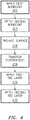
- FIG. 4 shows an exemplary process 200 for coating the substrate.
- initial substrate manufacture e.g., casting, finish machining, cleaning, and the like
- the bondcoat first layer 32 is applied 202 and the second layer 34 then applied 203. This may be done by cathodic arc deposition (or other methods as described above). Both stages may be performed in a single chamber (not shown) or in two chambers with transfer in between; whereafter the substrate(s) are transferred 204 to a second chamber (not shown) for TBC deposition.
- a surface preparation 206 may comprise heat treatment, surface finishing/compaction, further cleaning and/or grit blasting (e.g., in yet other chambers) prior to reaching the second chamber. There may also be thermal conditioning via heater (not shown).
- the TBC 28 or a first layer thereof may be applied 210 via EB-PVD in the second chamber.
- a further surface preparation (not shown) may follow and may require removal from the second chamber.
- a second or further TBC layer may be then applied 212 (e.g., by the same method in the same chamber but using at least a partially differing source (e.g., adding deposition from an ingot of an additive to deposition from an ingot of the base material (e.g., 7YSZ) or switching form an ingot of the 7YSZ to an ingot of the combined material)).
- a partially differing source e.g., adding deposition from an ingot of an additive to deposition from an ingot of the base material (e.g., 7YSZ) or switching form an ingot of the 7YSZ to an ingot of the combined material
- Additional layers may be deposited (whether in the aforementioned chambers or otherwise).
- FIG. 5 shows an exemplary cathodic arc deposition system 300 for depositing the two bondcoat layers 32 and 34.
- the system 300 includes a chamber wall structure 302 having an interior surface 303 bounding a chamber interior space 304.
- a hollow cathode assembly 306 is centrally located in the chamber interior 304 and comprises at least two cathodes 308, 310.
- the exemplary cathodes 308 and 310 are axially aligned end-to-end or spaced apart circumscribing a central vertical axis 520.
- one of the two cathodes has composition selected to yield one of the layers while the other cathode has composition selected to yield the other layer.
- a cup structure 312 having a cover or lid 314 defines a vessel having an interior 316.
- the exemplary interior contains chilled water (cooling system not shown) for cooling a magnet 318.
- the exemplary magnet is a permanent magnet having vertically oriented polarity (e.g., with a north-up orientation in this particular example).
- the water may also cool the cathodes which also cool by radiation.
- the exemplary lid 314 may be conductive to serve as a pathway for electrical transfer to the cathode(s).
- at least a rim flange of the cup 312 is also conductive and intervenes between the lid 314 and the upper cathode 308 to establish electrical connection therebetween.
- the magnet 318 is carried via a shaft 320 or similar means for reciprocal movement at least between an upper condition/position (solid lines) and a lower condition/position (broken lines).
- an actuator 322 e.g., electric, pneumatic, or hydraulic
- a control system 324 e.g., a micro-controller, computer, or the like.
- the shaft 320 passes freely through a cylindrical electrode 326 and is insulated relative to the electrode.
- a cathode power supply 330 creates a potential difference between the electrode 326 (and thus the cathodes) and the chamber wall 302.
- FIG. 5 further shows a conductive support plate 340 in contact with a lower rim of the lower cathode 310 to complete the electrical circuit thereacross.
- 340 is made from a highly conductive metal such as copper to help pull heat out of 310 (the lower cathode) and the 312 (cup structure).
- 342 is a non-conductive material such as a ceramic that supports 340 (plate) and separates it from 344 (metallic plate) and 350 (platter).
- the plate 340 is, in turn, supported by an insulator 342 (e.g., a ceramic plate) which, in turn, may be supported by an additional plate 344.
- an insulator 342 e.g., a ceramic plate
- FIG. 5 further shows a part holder or platter 350.
- the part holder is connected to a power supply 352 for applying a bias voltage relative to ground.
- An actuator allows the part holder to be lifted or lift the parts between respective positions for deposition from the two cathodes.
- rotary or other actuators may be provided to rotate the parts about axes (e.g., rotation in directions 530 about axes 532 for evenness of deposition).
- the upper cathode will be assumed to be associated with the bondcoat material 32 and the lower cathode with the bondcoat material 34.
- These cathodes may be formed of the respective materials or may have slightly altered combinations to account for species attrition during deposition. Accordingly, the magnet and parts are initially in the solid line raised positions associated with the upper cathode 308.
- FIG. 5 shows the magnetic field lines as 358.
- the cathodic arc extends between the associated negatively-charged cathode 308 and the positively-charged chamber wall 302 serving as an anode.
- a stream 362 of positively-charged atoms deposit on the part to form the associated layer 32 or 34.
- the residence time of the part and magnet in the first position will determine the thickness of the first layer 32. The appropriate thickness may be determined by experimental verification of deposition parameters.
- the position of the magnet 318 will determine the location of the cathodic arc.
- the magnet is downwardly shifted by the actuator 322 to the broken-line position.
- the parts are also shifted downwardly to remain at generally even level with the magnet.
Landscapes
- Chemical & Material Sciences (AREA)
- Engineering & Computer Science (AREA)
- Mechanical Engineering (AREA)
- Materials Engineering (AREA)
- Organic Chemistry (AREA)
- Metallurgy (AREA)
- Chemical Kinetics & Catalysis (AREA)
- General Engineering & Computer Science (AREA)
- Physical Vapour Deposition (AREA)
- Turbine Rotor Nozzle Sealing (AREA)
- Physics & Mathematics (AREA)
- Plasma & Fusion (AREA)
- Analytical Chemistry (AREA)
Claims (8)
- Procédé de dépôt par arc cathodique d'une première cathode (308) et d'une seconde cathode (310), le procédé comprenant :le placement d'un ou de plusieurs substrats dans une chambre (304) ;la génération d'un arc (360) entre la première cathode (308) et une anode (302) pour déposer un premier matériau de la première cathode ;la génération d'un arc entre la seconde cathode et l'anode pour déposer un second matériau de la seconde cathode ; etle déplacement d'une position relative d'un aimant (318) et des première et seconde cathodes pour passer du dépôt du premier matériau au dépôt du second matériau ; et comprenant en outre :
le déplacement vertical de substrats entre une première position associée au dépôt de la première cathode et une seconde position associée au dépôt de la seconde cathode. - Procédé selon la revendication 1, dans lequel :
le déplacement comprend le déplacement vertical de l'aimant entre une première position et une seconde position. - Procédé selon la revendication 1 ou 2, dans lequel :
l'anode est une paroi de la chambre. - Procédé selon l'une quelconque des revendications 1 à 3, dans lequel :le substrat comprend un superalliage à base de nickel ou à base de cobalt ;le premier matériau est un premier MCrAlY ; etle second matériau est un second MCrAlY différent du premier MCrAlY.
- Appareil (300) pour le dépôt par arc cathodique, l'appareil comprenant :une chambre (302) ;une première cathode (308) ;une seconde cathode (310) ;un aimant (318) ; etun actionneur (322) pour déplacer une position relative de l'aimant et des première et seconde cathodes pour passer du dépôt de la première cathode au dépôt de la seconde cathode ; et comprenant en outre :
un actionneur destiné à déplacer verticalement des substrats entre une première position associée au dépôt de la première cathode et une seconde position associée au dépôt de la seconde cathode. - Appareil selon la revendication 5, dans lequel :
le déplacement comprend le déplacement vertical de l'aimant entre une première position et une seconde position. - Appareil selon la revendication 5 ou la revendication 6, dans lequel :l'anode est une paroi (302) de la chambre (304) ; etla première cathode et la seconde cathode entourent un axe vertical (520) l'une au-dessus de l'autre.
- Appareil selon l'une quelconque des revendications 5 à 7, dans lequel :la première cathode comprend un premier MCrAlY ; etla seconde cathode comprend un second MCrAlY différent du premier MCrAlY.
Priority Applications (1)
| Application Number | Priority Date | Filing Date | Title |
|---|---|---|---|
| EP22181358.7A EP4130332A3 (fr) | 2013-03-15 | 2014-03-13 | Revêtement de barrière thermique résistant à l'éclatement |
Applications Claiming Priority (3)
| Application Number | Priority Date | Filing Date | Title |
|---|---|---|---|
| US201361800594P | 2013-03-15 | 2013-03-15 | |
| PCT/US2014/026452 WO2014151788A1 (fr) | 2013-03-15 | 2014-03-13 | Revêtement formant barrière thermique et résistant à la spallation |
| EP14767987.2A EP2971239B1 (fr) | 2013-03-15 | 2014-03-13 | Revêtement formant barrière thermique et résistant à la spallation |
Related Parent Applications (2)
| Application Number | Title | Priority Date | Filing Date |
|---|---|---|---|
| EP14767987.2A Division EP2971239B1 (fr) | 2013-03-15 | 2014-03-13 | Revêtement formant barrière thermique et résistant à la spallation |
| EP14767987.2A Division-Into EP2971239B1 (fr) | 2013-03-15 | 2014-03-13 | Revêtement formant barrière thermique et résistant à la spallation |
Related Child Applications (1)
| Application Number | Title | Priority Date | Filing Date |
|---|---|---|---|
| EP22181358.7A Division EP4130332A3 (fr) | 2013-03-15 | 2014-03-13 | Revêtement de barrière thermique résistant à l'éclatement |
Publications (2)
| Publication Number | Publication Date |
|---|---|
| EP3372707A1 EP3372707A1 (fr) | 2018-09-12 |
| EP3372707B1 true EP3372707B1 (fr) | 2022-06-29 |
Family
ID=51528406
Family Applications (3)
| Application Number | Title | Priority Date | Filing Date |
|---|---|---|---|
| EP18166188.5A Active EP3372707B1 (fr) | 2013-03-15 | 2014-03-13 | Revêtement de barrière thermique résistant à l'éclatement |
| EP14767987.2A Active EP2971239B1 (fr) | 2013-03-15 | 2014-03-13 | Revêtement formant barrière thermique et résistant à la spallation |
| EP22181358.7A Pending EP4130332A3 (fr) | 2013-03-15 | 2014-03-13 | Revêtement de barrière thermique résistant à l'éclatement |
Family Applications After (2)
| Application Number | Title | Priority Date | Filing Date |
|---|---|---|---|
| EP14767987.2A Active EP2971239B1 (fr) | 2013-03-15 | 2014-03-13 | Revêtement formant barrière thermique et résistant à la spallation |
| EP22181358.7A Pending EP4130332A3 (fr) | 2013-03-15 | 2014-03-13 | Revêtement de barrière thermique résistant à l'éclatement |
Country Status (3)
| Country | Link |
|---|---|
| US (2) | US9506140B2 (fr) |
| EP (3) | EP3372707B1 (fr) |
| WO (1) | WO2014151788A1 (fr) |
Families Citing this family (9)
| Publication number | Priority date | Publication date | Assignee | Title |
|---|---|---|---|---|
| US10364490B2 (en) * | 2013-12-10 | 2019-07-30 | United Technologies Corporation | Chromizing over cathodic arc coating |
| US9834835B2 (en) * | 2015-02-18 | 2017-12-05 | United Technologies Corporation | Fire containment coating system for titanium |
| US10436042B2 (en) | 2015-12-01 | 2019-10-08 | United Technologies Corporation | Thermal barrier coatings and methods |
| US11015252B2 (en) * | 2018-04-27 | 2021-05-25 | Applied Materials, Inc. | Protection of components from corrosion |
| DE102018112353A1 (de) * | 2018-05-23 | 2019-11-28 | Forschungszentrum Jülich GmbH | Verfahren zur Beschichtung eines Substrates mit einer Hohlraumstruktur |
| DE102018218018A1 (de) * | 2018-10-22 | 2020-04-23 | Siemens Aktiengesellschaft | Auftragschweißen von Nickelbasis-Superlegierungen mittels zweier Pulver, Pulvermischung und Verfahren |
| US10711621B1 (en) | 2019-02-01 | 2020-07-14 | Rolls-Royce Plc | Turbine vane assembly with ceramic matrix composite components and temperature management features |
| US10767495B2 (en) | 2019-02-01 | 2020-09-08 | Rolls-Royce Plc | Turbine vane assembly with cooling feature |
| CN110735117B (zh) * | 2019-11-29 | 2021-06-29 | 中国航发沈阳黎明航空发动机有限责任公司 | 一种双联体导向叶片热障涂层制备方法 |
Citations (8)
| Publication number | Priority date | Publication date | Assignee | Title |
|---|---|---|---|---|
| WO2001023643A2 (fr) * | 1999-09-29 | 2001-04-05 | Siemens Westinghouse Power Corporation | COUCHE BARRIERE POUR COMBINAISON DE SUPERALLIAGE A COUCHE PRIMAIRE McRAlY |
| US6226978B1 (en) * | 1998-04-07 | 2001-05-08 | Ghh Borsig Turbomaschinen Gmbh | Hot gas-carrying gas collection pipe of gas turbine |
| EP1700932A1 (fr) * | 2005-03-08 | 2006-09-13 | Siemens Aktiengesellschaft | Système de couches avec une couche pour l'inhibition de la diffusion |
| EP1801263A1 (fr) * | 2005-12-21 | 2007-06-27 | United Technologies Corporation | Couche de liaison de NiCoCrAly modifié par le platine pour revêtement de barrière thermique |
| EP1990440A1 (fr) * | 2007-04-30 | 2008-11-12 | United Technologies Corporation | Revêtement formant barrière thermique multicouche |
| WO2009038743A1 (fr) * | 2007-09-19 | 2009-03-26 | Siemens Energy, Inc. | Couche de liaison bimétallique pour un revêtement barrière thermique sur un superalliage |
| US20110268987A1 (en) * | 2009-01-08 | 2011-11-03 | Siemens Aktiengesellschaft | Mcralx Layer Having Differing Chromium and Aluminum Content |
| EP2682488A1 (fr) * | 2012-07-05 | 2014-01-08 | Siemens Aktiengesellschaft | Système de couche doté d'une couche de protection doble en NiCoCrAIY ayant une teneur en chrome variable et alliage |
Family Cites Families (28)
| Publication number | Priority date | Publication date | Assignee | Title |
|---|---|---|---|---|
| US4109061A (en) * | 1977-12-08 | 1978-08-22 | United Technologies Corporation | Method for altering the composition and structure of aluminum bearing overlay alloy coatings during deposition from metallic vapor |
| NL8700620A (nl) | 1987-03-16 | 1988-10-17 | Hauzer Holding | Kathode boogverdampingsinrichting alsmede werkwijze voor het bedrijven daarvan. |
| US4944858A (en) * | 1988-12-08 | 1990-07-31 | United Technologies Corporation | Method for applying diffusion aluminide coating |
| RU2147624C1 (ru) * | 1994-10-14 | 2000-04-20 | Сименс АГ | Защитный слой для защиты детали от коррозии, окисления и термической перегрузки, а также способ его изготовления |
| US5972185A (en) * | 1997-08-30 | 1999-10-26 | United Technologies Corporation | Cathodic arc vapor deposition apparatus (annular cathode) |
| DE59801544D1 (de) | 1997-11-03 | 2001-10-25 | Siemens Ag | Erzeugnis mit einem schichtsystem zum schutz gegen ein heisses aggressives gas |
| GB9821903D0 (en) | 1998-10-09 | 1998-12-02 | Rolls Royce Plc | A method of applying a coating to a metallic article and an apparatus for applying a coating to a metallic article |
| US6270318B1 (en) | 1999-12-20 | 2001-08-07 | United Technologies Corporation | Article having corrosion resistant coating |
| US6435835B1 (en) | 1999-12-20 | 2002-08-20 | United Technologies Corporation | Article having corrosion resistant coating |
| US6435830B1 (en) | 1999-12-20 | 2002-08-20 | United Technologies Corporation | Article having corrosion resistant coating |
| ATE386334T1 (de) | 2002-04-22 | 2008-03-15 | Pivot A S | Bogenbeschichtung mit drehkathoden |
| US7060366B2 (en) | 2003-02-19 | 2006-06-13 | General Electric Company | Article including a substrate with a metallic coating and a chromium-aluminide protective coating thereon, and its preparation and use in component restoration |
| JP3865705B2 (ja) | 2003-03-24 | 2007-01-10 | トーカロ株式会社 | 耐食性および耐熱性に優れる熱遮蔽皮膜被覆材並びにその製造方法 |
| DE102005060243A1 (de) | 2005-12-14 | 2007-06-21 | Man Turbo Ag | Verfahren zum Beschichten einer Schaufel und Schaufel einer Gasturbine |
| US20070231589A1 (en) | 2006-04-04 | 2007-10-04 | United Technologies Corporation | Thermal barrier coatings and processes for applying same |
| EP1925687A1 (fr) | 2006-11-24 | 2008-05-28 | Siemens Aktiengesellschaft | Couche à base d'un alliage en NiCoCrAl et système de couches |
| US7879203B2 (en) * | 2006-12-11 | 2011-02-01 | General Electric Company | Method and apparatus for cathodic arc ion plasma deposition |
| US20100254820A1 (en) | 2006-12-29 | 2010-10-07 | Michael Patrick Maly | Article with restored or regenerated structure |
| JP5082563B2 (ja) | 2007-04-18 | 2012-11-28 | 株式会社日立製作所 | 遮熱被覆を有する耐熱部材 |
| EP2128285A1 (fr) * | 2008-05-20 | 2009-12-02 | Siemens Aktiengesellschaft | Couche de MCrAIX à double épaisseur ayant des teneurs en cobalt et nickel différentes |
| EP2206806A1 (fr) | 2009-01-09 | 2010-07-14 | Siemens Aktiengesellschaft | Couche de MCrAIX à double épaisseur ayant des teneurs en cobalt et nickel différentes |
| GB0903199D0 (en) * | 2009-02-25 | 2009-04-08 | Univ Birmingham | Thermal barrier coatings for industrial gas turbines |
| RU2012140953A (ru) | 2010-02-26 | 2014-04-10 | Сименс Акциенгезелльшафт | Двухслойное металлическое связующее покрытие |
| US20120193226A1 (en) | 2011-02-02 | 2012-08-02 | Beers Russell A | Physical vapor deposition system |
| US20120193217A1 (en) | 2011-02-02 | 2012-08-02 | Tryon Brian S | Segmented post cathode |
| RU2566693C2 (ru) | 2011-07-08 | 2015-10-27 | Сименс Акциенгезелльшафт | Система слоев с двухслойным металлическим слоем |
| CN103796828B (zh) | 2011-09-12 | 2016-03-16 | 西门子公司 | 具有双层的MCrAlX金属层的层系统 |
| EP2639336A1 (fr) | 2012-03-16 | 2013-09-18 | Siemens Aktiengesellschaft | Système de couche doté d'une couche de protection doble en NiCoCrAIY ayant une teneur en chrome variable et alliage |
-
2014
- 2014-03-13 US US14/209,761 patent/US9506140B2/en active Active
- 2014-03-13 EP EP18166188.5A patent/EP3372707B1/fr active Active
- 2014-03-13 US US14/773,781 patent/US10113226B2/en active Active
- 2014-03-13 EP EP14767987.2A patent/EP2971239B1/fr active Active
- 2014-03-13 WO PCT/US2014/026452 patent/WO2014151788A1/fr not_active Ceased
- 2014-03-13 EP EP22181358.7A patent/EP4130332A3/fr active Pending
Patent Citations (8)
| Publication number | Priority date | Publication date | Assignee | Title |
|---|---|---|---|---|
| US6226978B1 (en) * | 1998-04-07 | 2001-05-08 | Ghh Borsig Turbomaschinen Gmbh | Hot gas-carrying gas collection pipe of gas turbine |
| WO2001023643A2 (fr) * | 1999-09-29 | 2001-04-05 | Siemens Westinghouse Power Corporation | COUCHE BARRIERE POUR COMBINAISON DE SUPERALLIAGE A COUCHE PRIMAIRE McRAlY |
| EP1700932A1 (fr) * | 2005-03-08 | 2006-09-13 | Siemens Aktiengesellschaft | Système de couches avec une couche pour l'inhibition de la diffusion |
| EP1801263A1 (fr) * | 2005-12-21 | 2007-06-27 | United Technologies Corporation | Couche de liaison de NiCoCrAly modifié par le platine pour revêtement de barrière thermique |
| EP1990440A1 (fr) * | 2007-04-30 | 2008-11-12 | United Technologies Corporation | Revêtement formant barrière thermique multicouche |
| WO2009038743A1 (fr) * | 2007-09-19 | 2009-03-26 | Siemens Energy, Inc. | Couche de liaison bimétallique pour un revêtement barrière thermique sur un superalliage |
| US20110268987A1 (en) * | 2009-01-08 | 2011-11-03 | Siemens Aktiengesellschaft | Mcralx Layer Having Differing Chromium and Aluminum Content |
| EP2682488A1 (fr) * | 2012-07-05 | 2014-01-08 | Siemens Aktiengesellschaft | Système de couche doté d'une couche de protection doble en NiCoCrAIY ayant une teneur en chrome variable et alliage |
Also Published As
| Publication number | Publication date |
|---|---|
| EP4130332A2 (fr) | 2023-02-08 |
| US9506140B2 (en) | 2016-11-29 |
| EP2971239B1 (fr) | 2018-05-16 |
| EP3372707A1 (fr) | 2018-09-12 |
| WO2014151788A1 (fr) | 2014-09-25 |
| EP2971239A1 (fr) | 2016-01-20 |
| US10113226B2 (en) | 2018-10-30 |
| US20160040281A1 (en) | 2016-02-11 |
| US20140272456A1 (en) | 2014-09-18 |
| EP2971239A4 (fr) | 2017-03-29 |
| EP4130332A3 (fr) | 2023-05-31 |
Similar Documents
| Publication | Publication Date | Title |
|---|---|---|
| EP3372707B1 (fr) | Revêtement de barrière thermique résistant à l'éclatement | |
| US9511572B2 (en) | Nanocrystalline interlayer coating for increasing service life of thermal barrier coating on high temperature components | |
| EP1591550B2 (fr) | Revêtement thermique ayant une couche d'interface pour une haute résistance à l'écaillage et basse conductivité thermique | |
| EP1254967B1 (fr) | Système amélioré de revêtement de barrière thermique de projection par plasma | |
| US6255001B1 (en) | Bond coat for a thermal barrier coating system and method therefor | |
| EP2607510B1 (fr) | Alliage en nickel-cobalt et revêtement de liaison et articles revêtus de liaison incorporant celui-ci | |
| EP1340833B1 (fr) | Revêtement hybride formant barrière thermique et méthode pour sa fabrication | |
| EP2258889B1 (fr) | Procédé et appareillage d'application d'un revêtement de barrière thermique | |
| EP2093307B1 (fr) | Revêtements de dépôts par arc cathodique pour composants de moteur à turbine | |
| EP0985745B1 (fr) | Couche de liaison pour système de revêtement de barrière thermique | |
| US20140186656A1 (en) | Spallation-Resistant Thermal Barrier Coating | |
| EP2213760B1 (fr) | Fondation de revêtement d'oxyde pour la promotion de l'adhérence de TBC | |
| CN117328014A (zh) | 可磨耗封严涂层及其制备方法、涡轮外环和应用 | |
| EP1400607A1 (fr) | Revêtement de barrière thermique présentant une résistance et une tenacité à la rupture améliorées | |
| JP2007239101A (ja) | 遮熱コーティングのためのボンドコーティング法 | |
| EP1431416A1 (fr) | Couche protectrice de Ti-Al-Cr-N | |
| US20070087210A1 (en) | High temperature insulative coating (XTR) | |
| Ali et al. | Intermediate PVD layers as diffusion barriers in turbine coating systems | |
| WO2026024701A1 (fr) | Couche de liaison métallique présentant une résistance améliorée à l'écaillage des tbc | |
| 高阳 et al. | Formation and behavior of thermal barrier coatings on nickel-base superalloys | |
| Rai | Development of Protective Coatings for Single Crystal Turbine Blades | |
| Zhu et al. | A Comparison of Thermal Shock Behavior between APS and Low-Energy VLPPS ZrO2-7% Y2O3 Thermal Barrier Coatings | |
| Lima et al. | A Comparison of Thermal Shock Behavior between APS and Low-Energy VLPPS ZrO2-7% Y2O3 Thermal Barrier Coatings |
Legal Events
| Date | Code | Title | Description |
|---|---|---|---|
| PUAI | Public reference made under article 153(3) epc to a published international application that has entered the european phase |
Free format text: ORIGINAL CODE: 0009012 |
|
| STAA | Information on the status of an ep patent application or granted ep patent |
Free format text: STATUS: THE APPLICATION HAS BEEN PUBLISHED |
|
| AC | Divisional application: reference to earlier application |
Ref document number: 2971239 Country of ref document: EP Kind code of ref document: P |
|
| AK | Designated contracting states |
Kind code of ref document: A1 Designated state(s): AL AT BE BG CH CY CZ DE DK EE ES FI FR GB GR HR HU IE IS IT LI LT LU LV MC MK MT NL NO PL PT RO RS SE SI SK SM TR |
|
| RIN1 | Information on inventor provided before grant (corrected) |
Inventor name: TRYON, BRIAN, S. Inventor name: UCASZ, MARK, T. Inventor name: TRUBELJA, MLADEN, F. Inventor name: ZIMMERMAN, BENJAMIN, J. Inventor name: GUPTA, DINESH, K. |
|
| STAA | Information on the status of an ep patent application or granted ep patent |
Free format text: STATUS: REQUEST FOR EXAMINATION WAS MADE |
|
| 17P | Request for examination filed |
Effective date: 20190312 |
|
| RBV | Designated contracting states (corrected) |
Designated state(s): AL AT BE BG CH CY CZ DE DK EE ES FI FR GB GR HR HU IE IS IT LI LT LU LV MC MK MT NL NO PL PT RO RS SE SI SK SM TR |
|
| GRAP | Despatch of communication of intention to grant a patent |
Free format text: ORIGINAL CODE: EPIDOSNIGR1 |
|
| STAA | Information on the status of an ep patent application or granted ep patent |
Free format text: STATUS: GRANT OF PATENT IS INTENDED |
|
| RIC1 | Information provided on ipc code assigned before grant |
Ipc: F01D 5/28 20060101ALI20190327BHEP Ipc: C23C 14/16 20060101ALI20190327BHEP Ipc: C23C 14/08 20060101AFI20190327BHEP Ipc: C23C 14/32 20060101ALI20190327BHEP |
|
| INTG | Intention to grant announced |
Effective date: 20190423 |
|
| GRAJ | Information related to disapproval of communication of intention to grant by the applicant or resumption of examination proceedings by the epo deleted |
Free format text: ORIGINAL CODE: EPIDOSDIGR1 |
|
| STAA | Information on the status of an ep patent application or granted ep patent |
Free format text: STATUS: REQUEST FOR EXAMINATION WAS MADE |
|
| GRAP | Despatch of communication of intention to grant a patent |
Free format text: ORIGINAL CODE: EPIDOSNIGR1 |
|
| INTC | Intention to grant announced (deleted) | ||
| STAA | Information on the status of an ep patent application or granted ep patent |
Free format text: STATUS: GRANT OF PATENT IS INTENDED |
|
| INTG | Intention to grant announced |
Effective date: 20191010 |
|
| GRAJ | Information related to disapproval of communication of intention to grant by the applicant or resumption of examination proceedings by the epo deleted |
Free format text: ORIGINAL CODE: EPIDOSDIGR1 |
|
| STAA | Information on the status of an ep patent application or granted ep patent |
Free format text: STATUS: REQUEST FOR EXAMINATION WAS MADE |
|
| GRAP | Despatch of communication of intention to grant a patent |
Free format text: ORIGINAL CODE: EPIDOSNIGR1 |
|
| STAA | Information on the status of an ep patent application or granted ep patent |
Free format text: STATUS: GRANT OF PATENT IS INTENDED |
|
| INTC | Intention to grant announced (deleted) | ||
| INTG | Intention to grant announced |
Effective date: 20200310 |
|
| GRAJ | Information related to disapproval of communication of intention to grant by the applicant or resumption of examination proceedings by the epo deleted |
Free format text: ORIGINAL CODE: EPIDOSDIGR1 |
|
| STAA | Information on the status of an ep patent application or granted ep patent |
Free format text: STATUS: REQUEST FOR EXAMINATION WAS MADE |
|
| INTC | Intention to grant announced (deleted) | ||
| GRAP | Despatch of communication of intention to grant a patent |
Free format text: ORIGINAL CODE: EPIDOSNIGR1 |
|
| STAA | Information on the status of an ep patent application or granted ep patent |
Free format text: STATUS: GRANT OF PATENT IS INTENDED |
|
| INTG | Intention to grant announced |
Effective date: 20200915 |
|
| GRAJ | Information related to disapproval of communication of intention to grant by the applicant or resumption of examination proceedings by the epo deleted |
Free format text: ORIGINAL CODE: EPIDOSDIGR1 |
|
| STAA | Information on the status of an ep patent application or granted ep patent |
Free format text: STATUS: REQUEST FOR EXAMINATION WAS MADE |
|
| INTC | Intention to grant announced (deleted) | ||
| GRAP | Despatch of communication of intention to grant a patent |
Free format text: ORIGINAL CODE: EPIDOSNIGR1 |
|
| RAP1 | Party data changed (applicant data changed or rights of an application transferred) |
Owner name: RAYTHEON TECHNOLOGIES CORPORATION |
|
| STAA | Information on the status of an ep patent application or granted ep patent |
Free format text: STATUS: GRANT OF PATENT IS INTENDED |
|
| INTG | Intention to grant announced |
Effective date: 20210325 |
|
| GRAJ | Information related to disapproval of communication of intention to grant by the applicant or resumption of examination proceedings by the epo deleted |
Free format text: ORIGINAL CODE: EPIDOSDIGR1 |
|
| STAA | Information on the status of an ep patent application or granted ep patent |
Free format text: STATUS: REQUEST FOR EXAMINATION WAS MADE |
|
| INTC | Intention to grant announced (deleted) | ||
| GRAP | Despatch of communication of intention to grant a patent |
Free format text: ORIGINAL CODE: EPIDOSNIGR1 |
|
| STAA | Information on the status of an ep patent application or granted ep patent |
Free format text: STATUS: GRANT OF PATENT IS INTENDED |
|
| INTG | Intention to grant announced |
Effective date: 20211004 |
|
| GRAS | Grant fee paid |
Free format text: ORIGINAL CODE: EPIDOSNIGR3 |
|
| GRAA | (expected) grant |
Free format text: ORIGINAL CODE: 0009210 |
|
| STAA | Information on the status of an ep patent application or granted ep patent |
Free format text: STATUS: THE PATENT HAS BEEN GRANTED |
|
| AC | Divisional application: reference to earlier application |
Ref document number: 2971239 Country of ref document: EP Kind code of ref document: P |
|
| AK | Designated contracting states |
Kind code of ref document: B1 Designated state(s): AL AT BE BG CH CY CZ DE DK EE ES FI FR GB GR HR HU IE IS IT LI LT LU LV MC MK MT NL NO PL PT RO RS SE SI SK SM TR |
|
| REG | Reference to a national code |
Ref country code: CH Ref legal event code: EP |
|
| REG | Reference to a national code |
Ref country code: AT Ref legal event code: REF Ref document number: 1501407 Country of ref document: AT Kind code of ref document: T Effective date: 20220715 |
|
| REG | Reference to a national code |
Ref country code: IE Ref legal event code: FG4D |
|
| REG | Reference to a national code |
Ref country code: DE Ref legal event code: R096 Ref document number: 602014084195 Country of ref document: DE |
|
| REG | Reference to a national code |
Ref country code: LT Ref legal event code: MG9D |
|
| PG25 | Lapsed in a contracting state [announced via postgrant information from national office to epo] |
Ref country code: SE Free format text: LAPSE BECAUSE OF FAILURE TO SUBMIT A TRANSLATION OF THE DESCRIPTION OR TO PAY THE FEE WITHIN THE PRESCRIBED TIME-LIMIT Effective date: 20220629 Ref country code: NO Free format text: LAPSE BECAUSE OF FAILURE TO SUBMIT A TRANSLATION OF THE DESCRIPTION OR TO PAY THE FEE WITHIN THE PRESCRIBED TIME-LIMIT Effective date: 20220929 Ref country code: LT Free format text: LAPSE BECAUSE OF FAILURE TO SUBMIT A TRANSLATION OF THE DESCRIPTION OR TO PAY THE FEE WITHIN THE PRESCRIBED TIME-LIMIT Effective date: 20220629 Ref country code: HR Free format text: LAPSE BECAUSE OF FAILURE TO SUBMIT A TRANSLATION OF THE DESCRIPTION OR TO PAY THE FEE WITHIN THE PRESCRIBED TIME-LIMIT Effective date: 20220629 Ref country code: GR Free format text: LAPSE BECAUSE OF FAILURE TO SUBMIT A TRANSLATION OF THE DESCRIPTION OR TO PAY THE FEE WITHIN THE PRESCRIBED TIME-LIMIT Effective date: 20220930 Ref country code: FI Free format text: LAPSE BECAUSE OF FAILURE TO SUBMIT A TRANSLATION OF THE DESCRIPTION OR TO PAY THE FEE WITHIN THE PRESCRIBED TIME-LIMIT Effective date: 20220629 Ref country code: BG Free format text: LAPSE BECAUSE OF FAILURE TO SUBMIT A TRANSLATION OF THE DESCRIPTION OR TO PAY THE FEE WITHIN THE PRESCRIBED TIME-LIMIT Effective date: 20220929 |
|
| REG | Reference to a national code |
Ref country code: NL Ref legal event code: MP Effective date: 20220629 |
|
| REG | Reference to a national code |
Ref country code: AT Ref legal event code: MK05 Ref document number: 1501407 Country of ref document: AT Kind code of ref document: T Effective date: 20220629 |
|
| PG25 | Lapsed in a contracting state [announced via postgrant information from national office to epo] |
Ref country code: RS Free format text: LAPSE BECAUSE OF FAILURE TO SUBMIT A TRANSLATION OF THE DESCRIPTION OR TO PAY THE FEE WITHIN THE PRESCRIBED TIME-LIMIT Effective date: 20220629 Ref country code: LV Free format text: LAPSE BECAUSE OF FAILURE TO SUBMIT A TRANSLATION OF THE DESCRIPTION OR TO PAY THE FEE WITHIN THE PRESCRIBED TIME-LIMIT Effective date: 20220629 |
|
| PG25 | Lapsed in a contracting state [announced via postgrant information from national office to epo] |
Ref country code: NL Free format text: LAPSE BECAUSE OF FAILURE TO SUBMIT A TRANSLATION OF THE DESCRIPTION OR TO PAY THE FEE WITHIN THE PRESCRIBED TIME-LIMIT Effective date: 20220629 |
|
| PG25 | Lapsed in a contracting state [announced via postgrant information from national office to epo] |
Ref country code: SM Free format text: LAPSE BECAUSE OF FAILURE TO SUBMIT A TRANSLATION OF THE DESCRIPTION OR TO PAY THE FEE WITHIN THE PRESCRIBED TIME-LIMIT Effective date: 20220629 Ref country code: SK Free format text: LAPSE BECAUSE OF FAILURE TO SUBMIT A TRANSLATION OF THE DESCRIPTION OR TO PAY THE FEE WITHIN THE PRESCRIBED TIME-LIMIT Effective date: 20220629 Ref country code: RO Free format text: LAPSE BECAUSE OF FAILURE TO SUBMIT A TRANSLATION OF THE DESCRIPTION OR TO PAY THE FEE WITHIN THE PRESCRIBED TIME-LIMIT Effective date: 20220629 Ref country code: PT Free format text: LAPSE BECAUSE OF FAILURE TO SUBMIT A TRANSLATION OF THE DESCRIPTION OR TO PAY THE FEE WITHIN THE PRESCRIBED TIME-LIMIT Effective date: 20221031 Ref country code: ES Free format text: LAPSE BECAUSE OF FAILURE TO SUBMIT A TRANSLATION OF THE DESCRIPTION OR TO PAY THE FEE WITHIN THE PRESCRIBED TIME-LIMIT Effective date: 20220629 Ref country code: EE Free format text: LAPSE BECAUSE OF FAILURE TO SUBMIT A TRANSLATION OF THE DESCRIPTION OR TO PAY THE FEE WITHIN THE PRESCRIBED TIME-LIMIT Effective date: 20220629 Ref country code: AT Free format text: LAPSE BECAUSE OF FAILURE TO SUBMIT A TRANSLATION OF THE DESCRIPTION OR TO PAY THE FEE WITHIN THE PRESCRIBED TIME-LIMIT Effective date: 20220629 |
|
| PG25 | Lapsed in a contracting state [announced via postgrant information from national office to epo] |
Ref country code: PL Free format text: LAPSE BECAUSE OF FAILURE TO SUBMIT A TRANSLATION OF THE DESCRIPTION OR TO PAY THE FEE WITHIN THE PRESCRIBED TIME-LIMIT Effective date: 20220629 Ref country code: IS Free format text: LAPSE BECAUSE OF FAILURE TO SUBMIT A TRANSLATION OF THE DESCRIPTION OR TO PAY THE FEE WITHIN THE PRESCRIBED TIME-LIMIT Effective date: 20221029 |
|
| REG | Reference to a national code |
Ref country code: DE Ref legal event code: R097 Ref document number: 602014084195 Country of ref document: DE |
|
| PG25 | Lapsed in a contracting state [announced via postgrant information from national office to epo] |
Ref country code: AL Free format text: LAPSE BECAUSE OF FAILURE TO SUBMIT A TRANSLATION OF THE DESCRIPTION OR TO PAY THE FEE WITHIN THE PRESCRIBED TIME-LIMIT Effective date: 20220629 |
|
| PG25 | Lapsed in a contracting state [announced via postgrant information from national office to epo] |
Ref country code: DK Free format text: LAPSE BECAUSE OF FAILURE TO SUBMIT A TRANSLATION OF THE DESCRIPTION OR TO PAY THE FEE WITHIN THE PRESCRIBED TIME-LIMIT Effective date: 20220629 Ref country code: CZ Free format text: LAPSE BECAUSE OF FAILURE TO SUBMIT A TRANSLATION OF THE DESCRIPTION OR TO PAY THE FEE WITHIN THE PRESCRIBED TIME-LIMIT Effective date: 20220629 |
|
| PLBE | No opposition filed within time limit |
Free format text: ORIGINAL CODE: 0009261 |
|
| STAA | Information on the status of an ep patent application or granted ep patent |
Free format text: STATUS: NO OPPOSITION FILED WITHIN TIME LIMIT |
|
| 26N | No opposition filed |
Effective date: 20230330 |
|
| P01 | Opt-out of the competence of the unified patent court (upc) registered |
Effective date: 20230521 |
|
| PG25 | Lapsed in a contracting state [announced via postgrant information from national office to epo] |
Ref country code: SI Free format text: LAPSE BECAUSE OF FAILURE TO SUBMIT A TRANSLATION OF THE DESCRIPTION OR TO PAY THE FEE WITHIN THE PRESCRIBED TIME-LIMIT Effective date: 20220629 |
|
| PG25 | Lapsed in a contracting state [announced via postgrant information from national office to epo] |
Ref country code: MC Free format text: LAPSE BECAUSE OF FAILURE TO SUBMIT A TRANSLATION OF THE DESCRIPTION OR TO PAY THE FEE WITHIN THE PRESCRIBED TIME-LIMIT Effective date: 20220629 |
|
| REG | Reference to a national code |
Ref country code: CH Ref legal event code: PL |
|
| REG | Reference to a national code |
Ref country code: BE Ref legal event code: MM Effective date: 20230331 |
|
| PG25 | Lapsed in a contracting state [announced via postgrant information from national office to epo] |
Ref country code: LU Free format text: LAPSE BECAUSE OF NON-PAYMENT OF DUE FEES Effective date: 20230313 |
|
| REG | Reference to a national code |
Ref country code: IE Ref legal event code: MM4A |
|
| PG25 | Lapsed in a contracting state [announced via postgrant information from national office to epo] |
Ref country code: LI Free format text: LAPSE BECAUSE OF NON-PAYMENT OF DUE FEES Effective date: 20230331 Ref country code: IT Free format text: LAPSE BECAUSE OF FAILURE TO SUBMIT A TRANSLATION OF THE DESCRIPTION OR TO PAY THE FEE WITHIN THE PRESCRIBED TIME-LIMIT Effective date: 20220629 Ref country code: IE Free format text: LAPSE BECAUSE OF NON-PAYMENT OF DUE FEES Effective date: 20230313 Ref country code: CH Free format text: LAPSE BECAUSE OF NON-PAYMENT OF DUE FEES Effective date: 20230331 |
|
| PG25 | Lapsed in a contracting state [announced via postgrant information from national office to epo] |
Ref country code: BE Free format text: LAPSE BECAUSE OF NON-PAYMENT OF DUE FEES Effective date: 20230331 |
|
| PG25 | Lapsed in a contracting state [announced via postgrant information from national office to epo] |
Ref country code: BG Free format text: LAPSE BECAUSE OF FAILURE TO SUBMIT A TRANSLATION OF THE DESCRIPTION OR TO PAY THE FEE WITHIN THE PRESCRIBED TIME-LIMIT Effective date: 20220629 |
|
| PG25 | Lapsed in a contracting state [announced via postgrant information from national office to epo] |
Ref country code: BG Free format text: LAPSE BECAUSE OF FAILURE TO SUBMIT A TRANSLATION OF THE DESCRIPTION OR TO PAY THE FEE WITHIN THE PRESCRIBED TIME-LIMIT Effective date: 20220629 |
|
| PG25 | Lapsed in a contracting state [announced via postgrant information from national office to epo] |
Ref country code: CY Free format text: LAPSE BECAUSE OF FAILURE TO SUBMIT A TRANSLATION OF THE DESCRIPTION OR TO PAY THE FEE WITHIN THE PRESCRIBED TIME-LIMIT; INVALID AB INITIO Effective date: 20140313 |
|
| PG25 | Lapsed in a contracting state [announced via postgrant information from national office to epo] |
Ref country code: HU Free format text: LAPSE BECAUSE OF FAILURE TO SUBMIT A TRANSLATION OF THE DESCRIPTION OR TO PAY THE FEE WITHIN THE PRESCRIBED TIME-LIMIT; INVALID AB INITIO Effective date: 20140313 |
|
| REG | Reference to a national code |
Ref country code: DE Ref legal event code: R081 Ref document number: 602014084195 Country of ref document: DE Owner name: RTX CORPORATION (N.D.GES.D. STAATES DELAWARE),, US Free format text: FORMER OWNER: RAYTHEON TECHNOLOGIES CORPORATION, FARMINGTON, CT, US |
|
| PG25 | Lapsed in a contracting state [announced via postgrant information from national office to epo] |
Ref country code: TR Free format text: LAPSE BECAUSE OF FAILURE TO SUBMIT A TRANSLATION OF THE DESCRIPTION OR TO PAY THE FEE WITHIN THE PRESCRIBED TIME-LIMIT Effective date: 20220629 |
|
| PGFP | Annual fee paid to national office [announced via postgrant information from national office to epo] |
Ref country code: GB Payment date: 20260220 Year of fee payment: 13 |
|
| PGFP | Annual fee paid to national office [announced via postgrant information from national office to epo] |
Ref country code: DE Payment date: 20260219 Year of fee payment: 13 |
|
| PGFP | Annual fee paid to national office [announced via postgrant information from national office to epo] |
Ref country code: FR Payment date: 20260219 Year of fee payment: 13 |