EP3373839B1 - Systèmes chirurgicaux robotisés de surveillance de forces appliquées - Google Patents
Systèmes chirurgicaux robotisés de surveillance de forces appliquées Download PDFInfo
- Publication number
- EP3373839B1 EP3373839B1 EP16864960.6A EP16864960A EP3373839B1 EP 3373839 B1 EP3373839 B1 EP 3373839B1 EP 16864960 A EP16864960 A EP 16864960A EP 3373839 B1 EP3373839 B1 EP 3373839B1
- Authority
- EP
- European Patent Office
- Prior art keywords
- robotic arm
- patient
- top plate
- sensor
- force
- Prior art date
- Legal status (The legal status is an assumption and is not a legal conclusion. Google has not performed a legal analysis and makes no representation as to the accuracy of the status listed.)
- Active
Links
Images


Classifications
-
- A—HUMAN NECESSITIES
- A61—MEDICAL OR VETERINARY SCIENCE; HYGIENE
- A61B—DIAGNOSIS; SURGERY; IDENTIFICATION
- A61B34/00—Computer-aided surgery; Manipulators or robots specially adapted for use in surgery
- A61B34/30—Surgical robots
-
- A—HUMAN NECESSITIES
- A61—MEDICAL OR VETERINARY SCIENCE; HYGIENE
- A61B—DIAGNOSIS; SURGERY; IDENTIFICATION
- A61B34/00—Computer-aided surgery; Manipulators or robots specially adapted for use in surgery
- A61B34/30—Surgical robots
- A61B34/35—Surgical robots for telesurgery
-
- A—HUMAN NECESSITIES
- A61—MEDICAL OR VETERINARY SCIENCE; HYGIENE
- A61B—DIAGNOSIS; SURGERY; IDENTIFICATION
- A61B34/00—Computer-aided surgery; Manipulators or robots specially adapted for use in surgery
- A61B34/30—Surgical robots
- A61B34/37—Leader-follower robots
-
- A—HUMAN NECESSITIES
- A61—MEDICAL OR VETERINARY SCIENCE; HYGIENE
- A61B—DIAGNOSIS; SURGERY; IDENTIFICATION
- A61B50/00—Containers, covers, furniture or holders specially adapted for surgical or diagnostic appliances or instruments, e.g. sterile covers
- A61B50/10—Furniture specially adapted for surgical or diagnostic appliances or instruments
- A61B50/13—Trolleys, e.g. carts
-
- A—HUMAN NECESSITIES
- A61—MEDICAL OR VETERINARY SCIENCE; HYGIENE
- A61B—DIAGNOSIS; SURGERY; IDENTIFICATION
- A61B90/00—Instruments, implements or accessories specially adapted for surgery or diagnosis and not covered by any of the groups A61B1/00 - A61B50/00, e.g. for luxation treatment or for protecting wound edges
- A61B90/06—Measuring instruments not otherwise provided for
-
- G—PHYSICS
- G01—MEASURING; TESTING
- G01L—MEASURING FORCE, STRESS, TORQUE, WORK, MECHANICAL POWER, MECHANICAL EFFICIENCY, OR FLUID PRESSURE
- G01L5/00—Apparatus for, or methods of, measuring force, work, mechanical power, or torque, specially adapted for specific purposes
- G01L5/22—Apparatus for, or methods of, measuring force, work, mechanical power, or torque, specially adapted for specific purposes for measuring the force applied to control members, e.g. control members of vehicles, triggers
- G01L5/226—Apparatus for, or methods of, measuring force, work, mechanical power, or torque, specially adapted for specific purposes for measuring the force applied to control members, e.g. control members of vehicles, triggers to manipulators, e.g. the force due to gripping
-
- A—HUMAN NECESSITIES
- A61—MEDICAL OR VETERINARY SCIENCE; HYGIENE
- A61B—DIAGNOSIS; SURGERY; IDENTIFICATION
- A61B90/00—Instruments, implements or accessories specially adapted for surgery or diagnosis and not covered by any of the groups A61B1/00 - A61B50/00, e.g. for luxation treatment or for protecting wound edges
- A61B90/06—Measuring instruments not otherwise provided for
- A61B2090/064—Measuring instruments not otherwise provided for for measuring force, pressure or mechanical tension
Definitions
- Robotic surgical systems are used in minimally invasive medical procedures because of their increased accuracy and expediency relative to handheld surgical instruments.
- a robotic arm supports a surgical instrument having an end effector mounted thereto by a wrist assembly.
- the robotic arm In operation, the robotic arm is moved to a position over a patient and then guides the surgical instrument into a small incision via a surgical port or a natural orifice of a patient to position the end effector at a work site within a patient's body.
- the height of the robotic arm over a patient may need to be adjusted (i.e., the robotic arm is lowered) to precisely position the end effector at a work site within a patient's body.
- the robotic arm and/or the surgical instrument attached thereto may exert a downward force on the anatomy, e.g., an abdominal wall of a patient.
- US 2009/248038 A1 describes a robotic surgical system having a robotic arm mounting a surgical instrument, and including a force detection system for improved sensing of forces on the surgical instrument and/or the robotic arm.
- WO 2007/041267 A2 describes a robotic system for harvesting and implanting follicular units.
- the system may comprise a force sensor coupled to a robotic arm and configured to stop a harvest process or an implant process if a sensed force exceeds a prescribed limit.
- US 6723106 B1 describes a robotic surgical system incorporating force sensors to sense forces between components of a robotic arm.
- US 2011/106141 A1 describes robotic surgical systems including a gripping unit, a manipulator unit, a treatment instrument drive unit, a gripping force detection unit, and a control unit.
- US 2009/088639 A1 describes a robotic device for performing ultrasound scans.
- the ultrasound transducer is mounted on a robotic arm.
- a force sensor may be provided to detect excessive force being applied between the transducer and the patient.
- US 2007/156157 A1 describes an imageless robotic surgical device.
- the device is configured to collect anatomical landmarks with a robot arm, combine landmark data with geometric planning parameters to generate position data, and automatically position a guiding tool mounted to the robotic arm.
- GB 1404227 A describes hydrostatic load cells which comprising a piston and a pressure member for supporting a load, wherein the pressure member may be connected to the piston by means of a pivot pin and bearing arrangement.
- the present invention provides a robotic surgical system as defined in claim 1.
- the robotic surgical system includes a robotic arm and a force detection system coupled to the robotic arm.
- the force detection system includes a sensor configured to detect a force being applied to a patient as the robotic arm is translated to a position relative to a patient.
- the robotic surgical system includes a control device in communication with the sensor of the force detection system.
- the control device is configured to change the position of the robotic arm relative to a patient when the force being detected by the sensor exceeds a predetermined force threshold.
- the force detection system further includes a base plate and a top plate.
- the sensor is disposed between the base plate and the top plate.
- a pivoting member is disposed between the base plate and the top plate to pivotably couple the base plate and the top plate to one another.
- the sensor includes a top portion and a bottom portion.
- the top portion of the sensor is coupled to the top plate and the bottom portion of the sensor is coupled to the base plate.
- the top plate may include a first end and a second end.
- the robotic arm may be located adjacent to the first end of the top plate.
- the base plate may include a first end and a second end.
- the sensor may be located between and coupled to the base plate and the top plate at the second end of the top plate and the second end of the base plate.
- the top plate may include a top surface and a bottom surface.
- the robotic arm may be coupled to the top surface of the top plate.
- the robotic surgical system of the present invention further includes a cart base.
- the cart base includes a vertical column having the force detection system supported thereon.
- the cart base may further include a plurality of casters coupled to the vertical column. The plurality of casters are configured to enable movement of the cart base.
- the vertical column may have an adjustable height to change a height of the robotic arm relative to a patient.
- the robotic surgical system may further include a surgical instrument attached to an end of the robotic arm.
- the senor may be a strain gauge load cell, a piezoelectric load cell, a hydraulic load cell, a pneumatic load cell, or an optical load cell.
- the robotic surgical system of the invention may be used in a non-claimed method of monitoring a force being applied on a patient.
- the method includes applying a force on a patient with a robotic arm, determining the force applied on the patient using a sensor coupled to the robotic arm, comparing the determined force applied on the patient with a predetermined force threshold, and adjusting a position of the robotic arm relative to the patient if the determined force applied on the patient exceeds the predetermined force threshold.
- applying the force on the patient with the robotic arm may include engaging the patient with a surgical instrument that is coupled to the robotic arm.
- adjusting the robotic arm relative to the patient may include disengaging the surgical instrument from the patient if the force applied exceeds the predetermined force threshold.
- determining the force applied on the patient may include measuring a tension load on the sensor resulting from a pivoting of a top plate that supports the robotic arm thereon relative to a base plate.
- the method may further include communicating the determined force applied on the patient to a control device.
- the control device may then compare the determined force applied on the patient with the predetermined force threshold.
- distal refers to that portion of the robotic surgical system or component thereof, that is closest to the patient
- proximal refers to that portion of the robotic surgical system or component thereof, that is farthest from the patient.
- a robotic surgical system including a force detection system configured to monitor and measure a force being applied on the anatomy of a patient by a robotic arm and/or a surgical instrument coupled to the robotic arm.
- the system comprises a control device configured to determine whether a force being applied on the anatomy of a patient by a robotic arm and/or a surgical instrument coupled thereto exceeds a patient specific predetermined force threshold and communicate a signal to the robotic arm to adjust the positioning thereof accordingly.
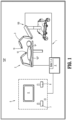
- Robotic surgical system 1 generally includes a plurality of surgical robotic arms 2, 3 having a surgical instrument, such as, for example, an electromechanical instrument 10 removably attached thereto; a control device 4; and an operating console 5 coupled with control device 4.
- Operating console 5 includes a display device 6, which is set up in particular to display three-dimensional images; and manual input devices 7, 8, by means of which a person (not shown), e.g., a surgeon, is able to telemanipulate robotic arms 2, 3 in a first operating mode, as known in principle to a person skilled in the art.
- a person e.g., a surgeon
- Each of the robotic arms 2, 3 may be composed of a plurality of members, which are connected through joints.
- Robotic arms 2, 3 may be driven by electric drives (not shown) that are connected to control device 4.
- Control device 4 e.g., a computer
- Control device 4 is set up to activate the drives, in particular by means of a computer program, in such a way that robotic arms 2, 3 and thus electromechanical instrument 10 (including the electromechanical end effector (not shown)) execute a desired movement according to a movement defined by means of manual input devices 7, 8.
- Control device 4 may also be set up in such a way that it regulates the movement of robotic arms 2, 3 and/or of the drives.
- Robotic surgical system 1 is configured for use on a patient "P" lying on a surgical table “ST” to be treated in a minimally invasive manner by means of a surgical instrument, e.g., electromechanical instrument 10.
- Robotic surgical system 1 may also include more than two robotic arms 2, 3, the additional robotic arms likewise being connected to control device 4 and being telemanipulatable by means of operating console 5.
- a surgical instrument for example, electromechanical instrument 10 (including the electromechanical end effector), may also be attached to the additional robotic arm.
- the robotic arms such as for example, robotic arm 3, is supported on a surgical cart assembly 100.
- Surgical cart assembly 100 may incorporate control device 4.
- the robotic arms, such as for example, robotic arm 2 may be coupled to the surgical table "ST.”
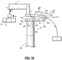
- Surgical cart assembly 100 is configured to move robotic arm 3 to a selected position within operating room "OR” ( FIG. 1 ) and to detect and control a force "F1" applied by robotic arm 3 on a patient "P," as will be described in detail below.
- Surgical cart assembly 100 generally includes robotic arm 3, electromechanical instrument 10, which is attached to robotic arm 3, a cart base 9 configured for supporting robotic arm 3 thereon, and a force detection assembly 200 disposed between robotic arm 3 and cart base 9.
- Cart base 9 of surgical cart assembly 100 includes a vertical column 102 and a platform 104 that supports vertical column 102 thereon.
- Vertical column 102 has a first end 102a and a second end 102b and defines a height "H1" of vertical column 102 therebetween.
- Vertical column 102 is telescopic such that height "H1" of vertical column 102 may be selectively adjusted.
- vertical column 102 includes a motor (not shown) configured to adjust height "H1" thereof.
- Platform 104 is fixed to second end 102b of vertical column 102 and includes four flanges 106a, 106b, 106c, and 106d, having respective casters 108a, 108b, 108c, and 108d (shown in phantom) attached thereto.
- platform 104 may include more than four flanges and casters or fewer than four flanges and casters. Further, in some embodiments, platform 104 may be detachably coupled to second end 102b of vertical column 102.
- force detection system 200 of surgical cart assembly 100 is configured to sense or detect force "F1" applied by electromechanical instrument 10 on a surface, for example, patient "P.”
- Force detection system 200 is interposed between an end 3b of robotic arm 3 and cart base 9.
- force detection assembly 200 may be interposed between robotic arm 2 and surgical table "ST.”
- Height “H1" of vertical column 102 may be adjusted (e.g., vertical column 102 may be telescopic as noted above) to correspondingly adjust a distance "D1" between an end 3a of robotic arm 3 and patient “P.”
- distance “D1" between end 3a of robotic arm 3 and patient “P” may be adjusted by adjusting a height "H2" between ends 3a, 3b of robotic arm 3 (e.g., robotic arm 3 may be telescopic).
- robotic arm 3 and/or electromechanical instrument 10 may apply force “F1" on patient “P” upon engaging the anatomy of patient “P.”
- force detection system 200 is configured to detect and measure force “F1” by measuring a resulting equal and opposing force “F2" being applied on robotic arm 3 and/or electromechanical instrument 10 by the anatomy of patient "P.”
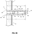
- Force detection system 200 includes a base plate 202, a top plate 204, and a pivot member 206 that pivotably couples base plate 202 and top plate 204 to one another.
- Base plate 202 includes a first end 202a and a second end 202b, wherein ends 202a, 202b define a length "L1" of base plate 202 therebetween.
- top plate 204 includes a first end 204a and a second end 204b, wherein ends 204a, 204b define a length "L2" of top plate 204 therebetween.
- length "L1" of base plate 202 is equal to length "L2" of top plate 204.
- length "L1" of base plate 202 may be greater than or less than length "L2" of top plate 204.
- base plate 202 includes a top surface 202c and a bottom surface 202d.
- top plate 204 includes a top surface 204c and a bottom surface 204d.
- surfaces 202c, 202d, 204c, and 204d of plates 202, 204, respectively, are planar.
- bottom surface 204d of top plate 204 and top surface 202c of base plate 202 define a gap distance "G" therebetween to space apart base plate 202 and top plate 204.
- base plate 202 and top plate 204 are parallel to one another when no force "F1" is being applied to patient "P.”
- Base plate 202 and top plate 204 are rectangular shaped. However, in some embodiments, base plate 202 and top plate 204 may assume a variety of shapes, such as, for example, squared, circular, triangular, or the like.
- Robotic arm 3 is supported on top surface 204c of top plate 204. Specifically, second end 3b of robotic arm 3 is coupled to top surface 204c of top plate 204 at the first end 204a thereof. However, in some embodiments, robotic arm 3 may be located on alternative positions along length "L2" of top plate 204. In some embodiments, second end 3b of robotic arm 3 is fixedly coupled to top surface 204c of top plate 204. Alternatively, in some embodiments, second end 3b of robotic arm 3 may be detachably coupled to top surface 204c of top plate 204.
- Pivot member 206 is disposed between base plate 202 and top plate 204 to allow top plate 204 to pivot relative to base plate 202.
- Pivot member 206 may be a hinge, a cylindrical member, or a rectangular member. However, in some embodiments, suitable alternatives for pivot member 206 are also contemplated.
- Pivot member 206 includes a top portion 206a and a bottom portion 206b. As noted above, pivot member 206 pivotably couples base plate 202 and top plate 204. Specifically, top portion 206a of pivot member 206 is coupled to bottom surface 204d of top plate 204 and bottom portion 206b of pivot member 206 is coupled to top surface 202c of base plate 202.
- portions 206a, 206b of pivot member 206 are fixedly coupled to surfaces 204d, 202c of plates 204, 202, respectively. However, in some embodiments, portions 206a, 206b of pivot member 206 may be detachably coupled to surfaces 204d, 202c of plates 204, 202, respectively.
- Pivot member 206 is disposed between top plate 204 and base plate 202 near the respective first ends 204a and 202a thereof. However, it is contemplated that pivot member 206 may be disposed at various locations between length “L2" of top plate 204 and length "L 1" of base plate 202. A distance “D2” is defined between pivot member 206 and first end 204a of top plate 204. It is contemplated that distance “D2" between pivot member 206 and first end 204a of top plate 204 may be stored in a memory device (not shown) in control device 4 and used in the calculation for determining force "F1" imparted by robotic arm 3 and/or electromechanical instrument 10 on a patient "P" ( FIG. 1 ).
- force detection system 200 also includes a load cell or sensor 208 configured to sense when top plate 204 pivots relative to base plate 202 to ultimately determine the force "F1" imparted by robotic arm 3 and/or electromechanical instrument 10 on a patient "P" ( FIG. 2A ).
- Sensor 208 is located between and coupled to base plate 202 and top plate 204 at respective second ends 202b, 204b thereof. However, it is contemplated that sensor 208 may be disposed at various locations between length "L2" of top plate 204 and length "L1" of base plate 202.
- Sensor 208 includes a top portion 208a and a bottom portion 208b.
- Top portion 208a of sensor 208 is coupled to bottom surface 204d of top plate 204 and bottom portion 208b of sensor 208 is coupled to top surface 202c of base plate 202.
- Portions 208a, 208b of sensor 208 are fixedly coupled to surfaces 204d, 202c of plates 204, 202, respectively.
- portions 208a, 208b of sensor 208 may be detachably coupled to surfaces 204d, 202c of plates 204, 202, respectively.
- sensor 208 may be a strain gauge load cell, a piezoelectric load cell, a hydraulic load cell, a pneumatic load cell, or an optical load cell.
- sensor 208 may be directed towards a strain gauge load cell configured to measure a tension load between base plate 202 and top plate 204 as second ends 202b, 204b of the respective plates 202, 204 are approximated such that sensor 208 is compressed therebetween.
- Sensor 208 includes a transducer (not shown), which converts a load “L” into a measurable electrical output, i.e., a signal readable by control device 4. Specifically, sensor 208 is configured to measure a change in load " ⁇ L” between base plate 202 and top plate 204 as top plate 204 rotates in a direction indicated by arrow "C” (see FIG. 3C ) about pivot member 206 with respect to base plate 202 when robotic arm 3 and/or electromechanical instrument 10 engages and imparts force "F1" on the anatomy of patient "P.”
- Robotic arm 3 includes another sensor 210 configured to sense when electromechanical instrument 10 makes contact with a fixed surface, for example, tissue of a patient "P.”
- robotic arm 3 has a patient facing surface 3c between ends 3a, 3b thereof, wherein surface 3c includes sensor 210.
- sensor 210 may be operably coupled to electromechanical instrument 10 such that contact between electromechanical instrument 10 and patient “P” is detected by sensor 210.
- sensor 210 detects when there is contact between robotic arm 3 and/or electromechanical instrument 10 and patient “P.”
- sensor 210 Upon contact, sensor 210 is configured to communicate a signal "S3" (see FIG. 3B ) to control device 4, which initiates a calculation of force "F1" being exerted by robotic arm 3 and/or electromechanical instrument 10 on the anatomy of patient "P.”
- robotic arm 3 is positioned adjacent patient “P" on surgical table “ST” such that first end 3a of robotic arm 3 is spaced apart from patient “P” by distance “D1 .”
- vertical column 102 of cart base assembly 100 has height “H1” and robotic arm 3 has height “H2.”
- sensor 208 of force detection system 200 measures a starting tension load "TL1" between base plate 202 and top plate 204.
- distance "D1" between first end 3a of robotic arm 3 and patient “P” is adjusted by adjusting height “H1” of vertical column 102 or height “H2” of robotic arm 3 (using a motor, not shown), in a direction indicated by arrow “A” in FIG. 3B .
- the continued movement of robotic arm 3 and electromechanical instrument 10 ultimately results in electromechanical instrument 10 engaging patient “P,” which exerts force “F1” on the anatomy thereof.
- the anatomy of patient “P” exerts an equal and opposing force "F2" on robotic arm 3 and/or electromechanical instrument 10.
- sensor 210 senses that a distal end of electromechanical instrument 10 has contacted patient "P,” and communicates signal “S3" to control device 4 to initiate the calculation of force “F1” and whether force “F1” exceeds a predetermine force "PF” threshold.
- sensor 208 communicates a signal "S1" to control device 4 including the measured change in load “ ⁇ L,” i.e., “TL1”-”TL2” between base plate 202 and top plate 204.
- control device 4 calculates force “F1” being exerted by robotic arm 3 and/or electromechanical instrument 10 on the anatomy of patient “P” and determines whether force “F1” exceeds predetermined force "PF” threshold.
- the predetermined force "PF” threshold may be calculated based on data relating to patient “P” stored in control device 4, e.g., age, height, weight, etc., of patient "P,” to determine the maximum amount of force “F1” that the anatomy of patient “P” can safely withstand without injury.
- control device 4 sends signal “S2" to robotic arm 3 and/or electromechanical instrument 10 to disengage from patient “P.”
- signal “S2" from control device 4 may also initiate an auditory or visual alarm to warn medical personnel.
- control device 4 may stop all movement of electromechanical instrument 10.
Landscapes
- Health & Medical Sciences (AREA)
- Surgery (AREA)
- Life Sciences & Earth Sciences (AREA)
- Engineering & Computer Science (AREA)
- Biomedical Technology (AREA)
- Public Health (AREA)
- Nuclear Medicine, Radiotherapy & Molecular Imaging (AREA)
- Veterinary Medicine (AREA)
- General Health & Medical Sciences (AREA)
- Heart & Thoracic Surgery (AREA)
- Medical Informatics (AREA)
- Molecular Biology (AREA)
- Animal Behavior & Ethology (AREA)
- Robotics (AREA)
- Oral & Maxillofacial Surgery (AREA)
- Pathology (AREA)
- Physics & Mathematics (AREA)
- General Physics & Mathematics (AREA)
- Manipulator (AREA)
Claims (7)
- Système chirurgical robotique (1), comprenant :un bras robotique (3) ;un instrument chirurgical (10) fixé à une extrémité du bras robotique ;un système de détection de force (200) accouplé au bras robotique, dans lequel le système de détection de force comporte un capteur (208) configuré pour détecter une force étant appliquée à un patient lorsque le bras robotique (3) ou l'instrument chirurgical (10), ou les deux, viennent en prise et exercent une force sur l'anatomie du patient lorsque le bras robotique est déplacé en translation vers une position par rapport à un patient ; etun dispositif de commande (4) en communication avec le capteur (208) du système de détection de force (200), le dispositif de commande étant configuré pour changer la position du bras robotique (3) par rapport à un patient lorsque ladite force étant détectée par le capteur dépasse un seuil de force prédéterminé,caractérisé en ce que :
le système de détection de force (200) comporte :une plaque de base (202) ;une plaque supérieure (204), le capteur (208) étant disposé entre la plaque de base (202) et la plaque supérieure (204) ; etun élément pivotant (206) disposé entre la plaque de base (202) et la plaque supérieure (204) pour accoupler de manière pivotante la plaque de base et la plaque supérieure l'une à l'autre ;le capteur (208) ayant une partie supérieure (208a) et une partie inférieure (208b), dans lequel la partie supérieure du capteur est accouplée à la plaque supérieure (204) et la partie inférieure du capteur est accouplée à la plaque de base (202) ; etle système chirurgical robotique comprend en outre une base de chariot (9) comportant une colonne verticale (102) sur laquelle est supporté le système de détection de force (200). - Système chirurgical robotique selon la revendication 1, dans lequel la plaque supérieure (204) a une première extrémité (204a) et une seconde extrémité (204b), le bras robotique (3) étant situé adjacent à la première extrémité de la plaque supérieure.
- Système chirurgical robotique selon la revendication 2, dans lequel la plaque de base (202) a une première extrémité (202a) et une seconde extrémité (202b), le capteur (208) étant situé entre la plaque de base (202) et la plaque supérieure (204) et accouplé à celles-ci au niveau de la seconde extrémité de la plaque supérieure et de la seconde extrémité de la plaque de base.
- Système chirurgical robotique selon l'une quelconque revendication précédente, dans lequel la plaque supérieure (204) a une surface supérieure (204c) et une surface inférieure (204d), le bras robotique (3) étant accouplé à la surface supérieure de la plaque supérieure.
- Système chirurgical robotique selon l'une quelconque revendication précédente, dans lequel la base de chariot (9) comporte une pluralité de roulettes (108a-d) accouplées à la colonne verticale, la pluralité de roulettes étant conçues pour permettre le mouvement de la base de chariot.
- Système chirurgical robotique selon l'une quelconque revendication précédente, dans lequel la colonne verticale (102) a une hauteur réglable pour changer une hauteur du bras robotique (3) par rapport à un patient.
- Système chirurgical robotique selon l'une quelconque revendication précédente, dans lequel le capteur (208) est une cellule de charge à jauge de contrainte, une cellule de charge piézoélectrique, une cellule de charge hydraulique, une cellule de charge pneumatique ou une cellule de charge optique.
Applications Claiming Priority (2)
| Application Number | Priority Date | Filing Date | Title |
|---|---|---|---|
| US201562254433P | 2015-11-12 | 2015-11-12 | |
| PCT/US2016/061221 WO2017083453A1 (fr) | 2015-11-12 | 2016-11-10 | Systèmes chirurgicaux robotisés et procédés de surveillance de forces appliquées |
Publications (3)
| Publication Number | Publication Date |
|---|---|
| EP3373839A1 EP3373839A1 (fr) | 2018-09-19 |
| EP3373839A4 EP3373839A4 (fr) | 2019-07-03 |
| EP3373839B1 true EP3373839B1 (fr) | 2024-09-04 |
Family
ID=58695243
Family Applications (1)
| Application Number | Title | Priority Date | Filing Date |
|---|---|---|---|
| EP16864960.6A Active EP3373839B1 (fr) | 2015-11-12 | 2016-11-10 | Systèmes chirurgicaux robotisés de surveillance de forces appliquées |
Country Status (4)
| Country | Link |
|---|---|
| US (2) | US10874475B2 (fr) |
| EP (1) | EP3373839B1 (fr) |
| CN (2) | CN113303915B (fr) |
| WO (1) | WO2017083453A1 (fr) |
Families Citing this family (58)
| Publication number | Priority date | Publication date | Assignee | Title |
|---|---|---|---|---|
| US20130317519A1 (en) | 2012-05-25 | 2013-11-28 | Hansen Medical, Inc. | Low friction instrument driver interface for robotic systems |
| US9668814B2 (en) | 2013-03-07 | 2017-06-06 | Hansen Medical, Inc. | Infinitely rotatable tool with finite rotating drive shafts |
| US20140277334A1 (en) | 2013-03-14 | 2014-09-18 | Hansen Medical, Inc. | Active drives for robotic catheter manipulators |
| US11213363B2 (en) | 2013-03-14 | 2022-01-04 | Auris Health, Inc. | Catheter tension sensing |
| US9326822B2 (en) | 2013-03-14 | 2016-05-03 | Hansen Medical, Inc. | Active drives for robotic catheter manipulators |
| US9173713B2 (en) | 2013-03-14 | 2015-11-03 | Hansen Medical, Inc. | Torque-based catheter articulation |
| US20140276647A1 (en) | 2013-03-15 | 2014-09-18 | Hansen Medical, Inc. | Vascular remote catheter manipulator |
| US9452018B2 (en) | 2013-03-15 | 2016-09-27 | Hansen Medical, Inc. | Rotational support for an elongate member |
| US9408669B2 (en) | 2013-03-15 | 2016-08-09 | Hansen Medical, Inc. | Active drive mechanism with finite range of motion |
| US20140276936A1 (en) | 2013-03-15 | 2014-09-18 | Hansen Medical, Inc. | Active drive mechanism for simultaneous rotation and translation |
| JP6656148B2 (ja) | 2013-10-24 | 2020-03-04 | オーリス ヘルス インコーポレイテッド | ロボット支援管腔内手術のためのシステムおよび関連する方法 |
| US10046140B2 (en) | 2014-04-21 | 2018-08-14 | Hansen Medical, Inc. | Devices, systems, and methods for controlling active drive systems |
| US10569052B2 (en) | 2014-05-15 | 2020-02-25 | Auris Health, Inc. | Anti-buckling mechanisms for catheters |
| US9561083B2 (en) | 2014-07-01 | 2017-02-07 | Auris Surgical Robotics, Inc. | Articulating flexible endoscopic tool with roll capabilities |
| CN113229942B (zh) | 2015-09-09 | 2024-11-12 | 奥瑞斯健康公司 | 手术器械装置操纵器 |
| US9949749B2 (en) | 2015-10-30 | 2018-04-24 | Auris Surgical Robotics, Inc. | Object capture with a basket |
| US10231793B2 (en) | 2015-10-30 | 2019-03-19 | Auris Health, Inc. | Object removal through a percutaneous suction tube |
| US9955986B2 (en) | 2015-10-30 | 2018-05-01 | Auris Surgical Robotics, Inc. | Basket apparatus |
| US10874475B2 (en) | 2015-11-12 | 2020-12-29 | Covidien Lp | Robotic surgical systems and methods for monitoring applied forces |
| US10454347B2 (en) | 2016-04-29 | 2019-10-22 | Auris Health, Inc. | Compact height torque sensing articulation axis assembly |
| US11241559B2 (en) | 2016-08-29 | 2022-02-08 | Auris Health, Inc. | Active drive for guidewire manipulation |
| KR20230096148A (ko) | 2016-08-31 | 2023-06-29 | 아우리스 헬스, 인코포레이티드 | 길이 보존 수술용 기구 |
| AU2017372911B2 (en) * | 2016-12-07 | 2020-07-02 | Orthosoft Ulc | Torque sensor sawblade anti-skiving system |
| US10244926B2 (en) | 2016-12-28 | 2019-04-02 | Auris Health, Inc. | Detecting endolumenal buckling of flexible instruments |
| US10543048B2 (en) * | 2016-12-28 | 2020-01-28 | Auris Health, Inc. | Flexible instrument insertion using an adaptive insertion force threshold |
| US10792119B2 (en) * | 2017-05-22 | 2020-10-06 | Ethicon Llc | Robotic arm cart and uses therefor |
| US10856948B2 (en) | 2017-05-31 | 2020-12-08 | Verb Surgical Inc. | Cart for robotic arms and method and apparatus for registering cart to surgical table |
| US10485623B2 (en) | 2017-06-01 | 2019-11-26 | Verb Surgical Inc. | Robotic arm cart with fine position adjustment features and uses therefor |
| US11052930B2 (en) * | 2017-06-16 | 2021-07-06 | Verb Surgical Inc. | Robotic arm cart having locking swivel joints and other position adjustment features and uses therefor |
| US10913145B2 (en) | 2017-06-20 | 2021-02-09 | Verb Surgical Inc. | Cart for robotic arms and method and apparatus for cartridge or magazine loading of arms |
| US11026758B2 (en) | 2017-06-28 | 2021-06-08 | Auris Health, Inc. | Medical robotics systems implementing axis constraints during actuation of one or more motorized joints |
| EP3444077A1 (fr) * | 2017-08-17 | 2019-02-20 | Siemens Healthcare GmbH | Procédé pour déterminer une position actuelle d'un effecteur d'extrémité de robot et système robotique |
| EP3678575B1 (fr) * | 2017-09-06 | 2023-08-23 | Covidien LP | Console de commande chirurgicale mobile |
| US10034721B1 (en) * | 2017-09-27 | 2018-07-31 | Verb Surgical Inc. | Robotic arm cart having shock absorbing mechanisms and uses therefor |
| US10470830B2 (en) | 2017-12-11 | 2019-11-12 | Auris Health, Inc. | Systems and methods for instrument based insertion architectures |
| US11510736B2 (en) | 2017-12-14 | 2022-11-29 | Auris Health, Inc. | System and method for estimating instrument location |
| CN111741715A (zh) * | 2017-12-29 | 2020-10-02 | 雷迪安特血氧测定公司 | 具有可调节组件的经腹胎儿脉搏血氧测定和/或子宫张力确定装置和系统及其使用方法 |
| WO2019143458A1 (fr) | 2018-01-17 | 2019-07-25 | Auris Health, Inc. | Systèmes robotiques chirurgicaux dotés de bras robotiques améliorés |
| EP3813632B1 (fr) | 2018-06-27 | 2026-04-22 | Auris Health, Inc. | Systèmes d'alignement et de fixation pour instruments médicaux |
| JP6650153B1 (ja) | 2018-09-06 | 2020-02-19 | リバーフィールド株式会社 | アーム装置、制御方法およびプログラム |
| EP3856001A4 (fr) | 2018-09-28 | 2022-06-22 | Auris Health, Inc. | Dispositifs, systèmes et méthodes d'entraînement manuel et robotique d'instruments médicaux |
| US10611391B1 (en) * | 2018-10-05 | 2020-04-07 | Corindus, Inc. | Mobile support and storage system for a medical device |
| EP3908224A4 (fr) | 2019-03-22 | 2022-10-19 | Auris Health, Inc. | Systèmes et procédés d'alignements d'entrées sur des instruments médicaux |
| US11896330B2 (en) | 2019-08-15 | 2024-02-13 | Auris Health, Inc. | Robotic medical system having multiple medical instruments |
| US11737845B2 (en) | 2019-09-30 | 2023-08-29 | Auris Inc. | Medical instrument with a capstan |
| WO2021137104A1 (fr) | 2019-12-31 | 2021-07-08 | Auris Health, Inc. | Système de poulie dynamique |
| KR20220123269A (ko) | 2019-12-31 | 2022-09-06 | 아우리스 헬스, 인코포레이티드 | 고급 바스켓 구동 모드 |
| WO2021186254A1 (fr) * | 2020-03-19 | 2021-09-23 | Auris Health, Inc. | Systèmes et procédés pour ajustements dynamiques basés sur des entrées de charge pour des systèmes robotisés |
| US20210402538A1 (en) * | 2020-06-30 | 2021-12-30 | Gulfstream Aerospace Corporation | Apparatus and method for holding and/or using a tool |
| US11609130B2 (en) * | 2021-01-19 | 2023-03-21 | Uneo Inc. | Cantilever force sensor |
| KR20240144087A (ko) | 2021-11-30 | 2024-10-02 | 엔도퀘스트 로보틱스 인코포레이티드 | 로봇 수술 시스템용 조종 가능한 오버튜브 조립체 |
| EP4440480A4 (fr) | 2021-11-30 | 2026-01-21 | Endoquest Robotics Inc | Agencements de dispositifs de commande pour systèmes chirurgicaux robotiques |
| JP2024545419A (ja) | 2021-11-30 | 2024-12-06 | エンドクエスト ロボティクス インコーポレイテッド | ロボット手術システム用のバリアドレープアダプタ |
| KR20260041932A (ko) | 2021-11-30 | 2026-03-27 | 엔도퀘스트 로보틱스 인코포레이티드 | 일회용 엔드 이펙터 |
| KR20240134850A (ko) | 2021-11-30 | 2024-09-10 | 엔도퀘스트 로보틱스 인코포레이티드 | 로봇 수술 시스템용 마스터 제어 시스템 |
| WO2023101949A1 (fr) | 2021-11-30 | 2023-06-08 | Endoquest, Inc. | Systèmes de positionnement à 5 degrés de liberté pour console patient |
| TWI836752B (zh) | 2021-11-30 | 2024-03-21 | 美商安督奎斯特機器人公司 | 用於機器人控制醫療裝置的力傳輸系統 |
| WO2023177785A1 (fr) | 2022-03-17 | 2023-09-21 | Mako Surgical Corp. | Techniques pour fixer ensemble des composants d'un ou de plusieurs chariots chirurgicaux |
Citations (1)
| Publication number | Priority date | Publication date | Assignee | Title |
|---|---|---|---|---|
| GB1404227A (en) * | 1972-08-26 | 1975-08-28 | Eyre D | Hydrostatic load cell |
Family Cites Families (18)
| Publication number | Priority date | Publication date | Assignee | Title |
|---|---|---|---|---|
| EP1133265B1 (fr) * | 1998-11-23 | 2004-07-07 | Microdexterity Systems Inc. | Manipulateur chirurgical |
| US8004229B2 (en) * | 2005-05-19 | 2011-08-23 | Intuitive Surgical Operations, Inc. | Software center and highly configurable robotic systems for surgery and other uses |
| US6865464B2 (en) * | 2002-12-17 | 2005-03-08 | Caterpillar Inc. | System for determining an implement arm position |
| US7181314B2 (en) * | 2003-11-24 | 2007-02-20 | Abb Research Ltd. | Industrial robot with controlled flexibility and simulated force for automated assembly |
| FR2871363B1 (fr) * | 2004-06-15 | 2006-09-01 | Medtech Sa | Dispositif robotise de guidage pour outil chirurgical |
| CA2763686C (fr) * | 2005-09-30 | 2014-07-08 | Restoration Robotics, Inc. | Systemes et methodes permettant d'aligner un outil sur un emplacement souhaite d'un objet |
| EP1915963A1 (fr) * | 2006-10-25 | 2008-04-30 | The European Atomic Energy Community (EURATOM), represented by the European Commission | Estimation de la force pour un systeme d'intervention chirurgicale robotisée à effraction minimale |
| DE102007046700A1 (de) | 2007-09-28 | 2009-04-16 | Siemens Ag | Ultraschallvorrichtung |
| US9895813B2 (en) * | 2008-03-31 | 2018-02-20 | Intuitive Surgical Operations, Inc. | Force and torque sensing in a surgical robot setup arm |
| US8594841B2 (en) * | 2008-12-31 | 2013-11-26 | Intuitive Surgical Operations, Inc. | Visual force feedback in a minimally invasive surgical procedure |
| JP4601727B2 (ja) | 2009-03-24 | 2010-12-22 | オリンパスメディカルシステムズ株式会社 | 内視鏡処置用ロボットシステム |
| JP5311294B2 (ja) * | 2010-04-28 | 2013-10-09 | 株式会社安川電機 | ロボットの接触位置検出装置 |
| EP2572838A1 (fr) | 2010-08-31 | 2013-03-27 | Kabushiki Kaisha Yaskawa Denki | Robot, système robotisé, dispositif de commande de robot et procédé de détermination d'état |
| DE102010043584A1 (de) | 2010-11-08 | 2012-05-10 | Kuka Laboratories Gmbh | Medizinscher Arbeitsplatz |
| US8716973B1 (en) | 2011-02-28 | 2014-05-06 | Moog Inc. | Haptic user interface |
| EP2797510B1 (fr) * | 2011-12-30 | 2016-03-23 | Mako Surgical Corp. | Système pour une chirurgie robotique à base d'images |
| EP3610820B1 (fr) | 2014-03-17 | 2023-08-02 | Intuitive Surgical Operations, Inc. | Procédés et dispositifs de suivi la pose de table à l'aide de marqueurs de repère |
| US10874475B2 (en) | 2015-11-12 | 2020-12-29 | Covidien Lp | Robotic surgical systems and methods for monitoring applied forces |
-
2016
- 2016-11-10 US US15/766,957 patent/US10874475B2/en active Active
- 2016-11-10 WO PCT/US2016/061221 patent/WO2017083453A1/fr not_active Ceased
- 2016-11-10 CN CN202110576814.XA patent/CN113303915B/zh active Active
- 2016-11-10 CN CN201680065313.2A patent/CN108348296B/zh active Active
- 2016-11-10 EP EP16864960.6A patent/EP3373839B1/fr active Active
-
2020
- 2020-12-08 US US17/114,663 patent/US11628034B2/en active Active
Patent Citations (1)
| Publication number | Priority date | Publication date | Assignee | Title |
|---|---|---|---|---|
| GB1404227A (en) * | 1972-08-26 | 1975-08-28 | Eyre D | Hydrostatic load cell |
Also Published As
| Publication number | Publication date |
|---|---|
| CN113303915B (zh) | 2024-04-12 |
| US20210106396A1 (en) | 2021-04-15 |
| WO2017083453A1 (fr) | 2017-05-18 |
| EP3373839A4 (fr) | 2019-07-03 |
| CN108348296B (zh) | 2021-06-11 |
| US10874475B2 (en) | 2020-12-29 |
| CN108348296A (zh) | 2018-07-31 |
| US11628034B2 (en) | 2023-04-18 |
| EP3373839A1 (fr) | 2018-09-19 |
| CN113303915A (zh) | 2021-08-27 |
| US20180296299A1 (en) | 2018-10-18 |
Similar Documents
| Publication | Publication Date | Title |
|---|---|---|
| EP3373839B1 (fr) | Systèmes chirurgicaux robotisés de surveillance de forces appliquées | |
| US12048499B2 (en) | Robotic surgical system torque transduction sensing | |
| US11478316B2 (en) | Surgical robot system | |
| JP7127128B2 (ja) | 手術ロボットシステム及びその手術器具 | |
| JP7717872B2 (ja) | 多目的医療機器 | |
| KR20240093727A (ko) | 수술 스테이플러를 위한 통합형 센서 | |
| EP4419036A1 (fr) | Capteurs intégrés pour instruments énergétiques | |
| EP3668471A1 (fr) | Table d'opération pour systèmes chirurgicaux robotiques |
Legal Events
| Date | Code | Title | Description |
|---|---|---|---|
| STAA | Information on the status of an ep patent application or granted ep patent |
Free format text: STATUS: THE INTERNATIONAL PUBLICATION HAS BEEN MADE |
|
| PUAI | Public reference made under article 153(3) epc to a published international application that has entered the european phase |
Free format text: ORIGINAL CODE: 0009012 |
|
| STAA | Information on the status of an ep patent application or granted ep patent |
Free format text: STATUS: REQUEST FOR EXAMINATION WAS MADE |
|
| 17P | Request for examination filed |
Effective date: 20180611 |
|
| AK | Designated contracting states |
Kind code of ref document: A1 Designated state(s): AL AT BE BG CH CY CZ DE DK EE ES FI FR GB GR HR HU IE IS IT LI LT LU LV MC MK MT NL NO PL PT RO RS SE SI SK SM TR |
|
| AX | Request for extension of the european patent |
Extension state: BA ME |
|
| DAV | Request for validation of the european patent (deleted) | ||
| DAX | Request for extension of the european patent (deleted) | ||
| REG | Reference to a national code |
Ref country code: DE Ref legal event code: R079 Free format text: PREVIOUS MAIN CLASS: A61B0034300000 Ipc: A61B0034370000 |
|
| A4 | Supplementary search report drawn up and despatched |
Effective date: 20190605 |
|
| RIC1 | Information provided on ipc code assigned before grant |
Ipc: G01L 5/22 20060101ALI20190529BHEP Ipc: A61B 34/37 20160101AFI20190529BHEP Ipc: G01L 1/00 20060101ALI20190529BHEP Ipc: A61B 50/13 20160101ALI20190529BHEP |
|
| STAA | Information on the status of an ep patent application or granted ep patent |
Free format text: STATUS: EXAMINATION IS IN PROGRESS |
|
| 17Q | First examination report despatched |
Effective date: 20230310 |
|
| GRAP | Despatch of communication of intention to grant a patent |
Free format text: ORIGINAL CODE: EPIDOSNIGR1 |
|
| STAA | Information on the status of an ep patent application or granted ep patent |
Free format text: STATUS: GRANT OF PATENT IS INTENDED |
|
| INTG | Intention to grant announced |
Effective date: 20240408 |
|
| GRAS | Grant fee paid |
Free format text: ORIGINAL CODE: EPIDOSNIGR3 |
|
| GRAA | (expected) grant |
Free format text: ORIGINAL CODE: 0009210 |
|
| STAA | Information on the status of an ep patent application or granted ep patent |
Free format text: STATUS: THE PATENT HAS BEEN GRANTED |
|
| AK | Designated contracting states |
Kind code of ref document: B1 Designated state(s): AL AT BE BG CH CY CZ DE DK EE ES FI FR GB GR HR HU IE IS IT LI LT LU LV MC MK MT NL NO PL PT RO RS SE SI SK SM TR |
|
| REG | Reference to a national code |
Ref country code: GB Ref legal event code: FG4D |
|
| REG | Reference to a national code |
Ref country code: CH Ref legal event code: EP |
|
| REG | Reference to a national code |
Ref country code: IE Ref legal event code: FG4D Ref country code: NL Ref legal event code: FP |
|
| REG | Reference to a national code |
Ref country code: DE Ref legal event code: R096 Ref document number: 602016089287 Country of ref document: DE |
|
| REG | Reference to a national code |
Ref country code: LT Ref legal event code: MG9D |
|
| PG25 | Lapsed in a contracting state [announced via postgrant information from national office to epo] |
Ref country code: NO Free format text: LAPSE BECAUSE OF FAILURE TO SUBMIT A TRANSLATION OF THE DESCRIPTION OR TO PAY THE FEE WITHIN THE PRESCRIBED TIME-LIMIT Effective date: 20241204 |
|
| PG25 | Lapsed in a contracting state [announced via postgrant information from national office to epo] |
Ref country code: PL Free format text: LAPSE BECAUSE OF FAILURE TO SUBMIT A TRANSLATION OF THE DESCRIPTION OR TO PAY THE FEE WITHIN THE PRESCRIBED TIME-LIMIT Effective date: 20240904 Ref country code: GR Free format text: LAPSE BECAUSE OF FAILURE TO SUBMIT A TRANSLATION OF THE DESCRIPTION OR TO PAY THE FEE WITHIN THE PRESCRIBED TIME-LIMIT Effective date: 20241205 Ref country code: FI Free format text: LAPSE BECAUSE OF FAILURE TO SUBMIT A TRANSLATION OF THE DESCRIPTION OR TO PAY THE FEE WITHIN THE PRESCRIBED TIME-LIMIT Effective date: 20240904 |
|
| PG25 | Lapsed in a contracting state [announced via postgrant information from national office to epo] |
Ref country code: BG Free format text: LAPSE BECAUSE OF FAILURE TO SUBMIT A TRANSLATION OF THE DESCRIPTION OR TO PAY THE FEE WITHIN THE PRESCRIBED TIME-LIMIT Effective date: 20240904 |
|
| PG25 | Lapsed in a contracting state [announced via postgrant information from national office to epo] |
Ref country code: LV Free format text: LAPSE BECAUSE OF FAILURE TO SUBMIT A TRANSLATION OF THE DESCRIPTION OR TO PAY THE FEE WITHIN THE PRESCRIBED TIME-LIMIT Effective date: 20240904 |
|
| PG25 | Lapsed in a contracting state [announced via postgrant information from national office to epo] |
Ref country code: HR Free format text: LAPSE BECAUSE OF FAILURE TO SUBMIT A TRANSLATION OF THE DESCRIPTION OR TO PAY THE FEE WITHIN THE PRESCRIBED TIME-LIMIT Effective date: 20240904 |
|
| PG25 | Lapsed in a contracting state [announced via postgrant information from national office to epo] |
Ref country code: ES Free format text: LAPSE BECAUSE OF FAILURE TO SUBMIT A TRANSLATION OF THE DESCRIPTION OR TO PAY THE FEE WITHIN THE PRESCRIBED TIME-LIMIT Effective date: 20240904 Ref country code: RS Free format text: LAPSE BECAUSE OF FAILURE TO SUBMIT A TRANSLATION OF THE DESCRIPTION OR TO PAY THE FEE WITHIN THE PRESCRIBED TIME-LIMIT Effective date: 20241204 |
|
| PG25 | Lapsed in a contracting state [announced via postgrant information from national office to epo] |
Ref country code: RS Free format text: LAPSE BECAUSE OF FAILURE TO SUBMIT A TRANSLATION OF THE DESCRIPTION OR TO PAY THE FEE WITHIN THE PRESCRIBED TIME-LIMIT Effective date: 20241204 Ref country code: PL Free format text: LAPSE BECAUSE OF FAILURE TO SUBMIT A TRANSLATION OF THE DESCRIPTION OR TO PAY THE FEE WITHIN THE PRESCRIBED TIME-LIMIT Effective date: 20240904 Ref country code: NO Free format text: LAPSE BECAUSE OF FAILURE TO SUBMIT A TRANSLATION OF THE DESCRIPTION OR TO PAY THE FEE WITHIN THE PRESCRIBED TIME-LIMIT Effective date: 20241204 Ref country code: LV Free format text: LAPSE BECAUSE OF FAILURE TO SUBMIT A TRANSLATION OF THE DESCRIPTION OR TO PAY THE FEE WITHIN THE PRESCRIBED TIME-LIMIT Effective date: 20240904 Ref country code: HR Free format text: LAPSE BECAUSE OF FAILURE TO SUBMIT A TRANSLATION OF THE DESCRIPTION OR TO PAY THE FEE WITHIN THE PRESCRIBED TIME-LIMIT Effective date: 20240904 Ref country code: GR Free format text: LAPSE BECAUSE OF FAILURE TO SUBMIT A TRANSLATION OF THE DESCRIPTION OR TO PAY THE FEE WITHIN THE PRESCRIBED TIME-LIMIT Effective date: 20241205 Ref country code: FI Free format text: LAPSE BECAUSE OF FAILURE TO SUBMIT A TRANSLATION OF THE DESCRIPTION OR TO PAY THE FEE WITHIN THE PRESCRIBED TIME-LIMIT Effective date: 20240904 Ref country code: ES Free format text: LAPSE BECAUSE OF FAILURE TO SUBMIT A TRANSLATION OF THE DESCRIPTION OR TO PAY THE FEE WITHIN THE PRESCRIBED TIME-LIMIT Effective date: 20240904 Ref country code: BG Free format text: LAPSE BECAUSE OF FAILURE TO SUBMIT A TRANSLATION OF THE DESCRIPTION OR TO PAY THE FEE WITHIN THE PRESCRIBED TIME-LIMIT Effective date: 20240904 |
|
| REG | Reference to a national code |
Ref country code: AT Ref legal event code: MK05 Ref document number: 1719571 Country of ref document: AT Kind code of ref document: T Effective date: 20240904 |
|
| PG25 | Lapsed in a contracting state [announced via postgrant information from national office to epo] |
Ref country code: IS Free format text: LAPSE BECAUSE OF FAILURE TO SUBMIT A TRANSLATION OF THE DESCRIPTION OR TO PAY THE FEE WITHIN THE PRESCRIBED TIME-LIMIT Effective date: 20250104 Ref country code: PT Free format text: LAPSE BECAUSE OF FAILURE TO SUBMIT A TRANSLATION OF THE DESCRIPTION OR TO PAY THE FEE WITHIN THE PRESCRIBED TIME-LIMIT Effective date: 20250106 |
|
| PG25 | Lapsed in a contracting state [announced via postgrant information from national office to epo] |
Ref country code: RO Free format text: LAPSE BECAUSE OF FAILURE TO SUBMIT A TRANSLATION OF THE DESCRIPTION OR TO PAY THE FEE WITHIN THE PRESCRIBED TIME-LIMIT Effective date: 20240904 Ref country code: SM Free format text: LAPSE BECAUSE OF FAILURE TO SUBMIT A TRANSLATION OF THE DESCRIPTION OR TO PAY THE FEE WITHIN THE PRESCRIBED TIME-LIMIT Effective date: 20240904 |
|
| PG25 | Lapsed in a contracting state [announced via postgrant information from national office to epo] |
Ref country code: EE Free format text: LAPSE BECAUSE OF FAILURE TO SUBMIT A TRANSLATION OF THE DESCRIPTION OR TO PAY THE FEE WITHIN THE PRESCRIBED TIME-LIMIT Effective date: 20240904 Ref country code: AT Free format text: LAPSE BECAUSE OF FAILURE TO SUBMIT A TRANSLATION OF THE DESCRIPTION OR TO PAY THE FEE WITHIN THE PRESCRIBED TIME-LIMIT Effective date: 20240904 |
|
| PG25 | Lapsed in a contracting state [announced via postgrant information from national office to epo] |
Ref country code: CZ Free format text: LAPSE BECAUSE OF FAILURE TO SUBMIT A TRANSLATION OF THE DESCRIPTION OR TO PAY THE FEE WITHIN THE PRESCRIBED TIME-LIMIT Effective date: 20240904 |
|
| PG25 | Lapsed in a contracting state [announced via postgrant information from national office to epo] |
Ref country code: IT Free format text: LAPSE BECAUSE OF FAILURE TO SUBMIT A TRANSLATION OF THE DESCRIPTION OR TO PAY THE FEE WITHIN THE PRESCRIBED TIME-LIMIT Effective date: 20240904 Ref country code: SK Free format text: LAPSE BECAUSE OF FAILURE TO SUBMIT A TRANSLATION OF THE DESCRIPTION OR TO PAY THE FEE WITHIN THE PRESCRIBED TIME-LIMIT Effective date: 20240904 |
|
| REG | Reference to a national code |
Ref country code: DE Ref legal event code: R097 Ref document number: 602016089287 Country of ref document: DE |
|
| REG | Reference to a national code |
Ref country code: CH Ref legal event code: PL |
|
| PG25 | Lapsed in a contracting state [announced via postgrant information from national office to epo] |
Ref country code: MC Free format text: LAPSE BECAUSE OF FAILURE TO SUBMIT A TRANSLATION OF THE DESCRIPTION OR TO PAY THE FEE WITHIN THE PRESCRIBED TIME-LIMIT Effective date: 20240904 |
|
| PG25 | Lapsed in a contracting state [announced via postgrant information from national office to epo] |
Ref country code: DK Free format text: LAPSE BECAUSE OF FAILURE TO SUBMIT A TRANSLATION OF THE DESCRIPTION OR TO PAY THE FEE WITHIN THE PRESCRIBED TIME-LIMIT Effective date: 20240904 |
|
| PLBE | No opposition filed within time limit |
Free format text: ORIGINAL CODE: 0009261 |
|
| STAA | Information on the status of an ep patent application or granted ep patent |
Free format text: STATUS: NO OPPOSITION FILED WITHIN TIME LIMIT |
|
| PG25 | Lapsed in a contracting state [announced via postgrant information from national office to epo] |
Ref country code: LU Free format text: LAPSE BECAUSE OF NON-PAYMENT OF DUE FEES Effective date: 20241110 |
|
| REG | Reference to a national code |
Ref country code: CH Ref legal event code: PL |
|
| PG25 | Lapsed in a contracting state [announced via postgrant information from national office to epo] |
Ref country code: CH Free format text: LAPSE BECAUSE OF NON-PAYMENT OF DUE FEES Effective date: 20241130 |
|
| 26N | No opposition filed |
Effective date: 20250605 |
|
| REG | Reference to a national code |
Ref country code: BE Ref legal event code: MM Effective date: 20241130 |
|
| PG25 | Lapsed in a contracting state [announced via postgrant information from national office to epo] |
Ref country code: SE Free format text: LAPSE BECAUSE OF FAILURE TO SUBMIT A TRANSLATION OF THE DESCRIPTION OR TO PAY THE FEE WITHIN THE PRESCRIBED TIME-LIMIT Effective date: 20240904 |
|
| PG25 | Lapsed in a contracting state [announced via postgrant information from national office to epo] |
Ref country code: BE Free format text: LAPSE BECAUSE OF NON-PAYMENT OF DUE FEES Effective date: 20241130 |
|
| PG25 | Lapsed in a contracting state [announced via postgrant information from national office to epo] |
Ref country code: FR Free format text: LAPSE BECAUSE OF NON-PAYMENT OF DUE FEES Effective date: 20241130 |
|
| PG25 | Lapsed in a contracting state [announced via postgrant information from national office to epo] |
Ref country code: IE Free format text: LAPSE BECAUSE OF NON-PAYMENT OF DUE FEES Effective date: 20241110 |
|
| PGFP | Annual fee paid to national office [announced via postgrant information from national office to epo] |
Ref country code: NL Payment date: 20251022 Year of fee payment: 10 |
|
| PGFP | Annual fee paid to national office [announced via postgrant information from national office to epo] |
Ref country code: DE Payment date: 20251022 Year of fee payment: 10 |
|
| PGFP | Annual fee paid to national office [announced via postgrant information from national office to epo] |
Ref country code: GB Payment date: 20251022 Year of fee payment: 10 |
|
| PG25 | Lapsed in a contracting state [announced via postgrant information from national office to epo] |
Ref country code: HU Free format text: LAPSE BECAUSE OF FAILURE TO SUBMIT A TRANSLATION OF THE DESCRIPTION OR TO PAY THE FEE WITHIN THE PRESCRIBED TIME-LIMIT; INVALID AB INITIO Effective date: 20161110 |
|
| PG25 | Lapsed in a contracting state [announced via postgrant information from national office to epo] |
Ref country code: CY Free format text: LAPSE BECAUSE OF FAILURE TO SUBMIT A TRANSLATION OF THE DESCRIPTION OR TO PAY THE FEE WITHIN THE PRESCRIBED TIME-LIMIT; INVALID AB INITIO Effective date: 20161110 |