EP3375573B1 - Bohrhammer - Google Patents
Bohrhammer Download PDFInfo
- Publication number
- EP3375573B1 EP3375573B1 EP18157794.1A EP18157794A EP3375573B1 EP 3375573 B1 EP3375573 B1 EP 3375573B1 EP 18157794 A EP18157794 A EP 18157794A EP 3375573 B1 EP3375573 B1 EP 3375573B1
- Authority
- EP
- European Patent Office
- Prior art keywords
- guide rod
- main body
- connector
- elastic body
- opening
- Prior art date
- Legal status (The legal status is an assumption and is not a legal conclusion. Google has not performed a legal analysis and makes no representation as to the accuracy of the status listed.)
- Active
Links
Images


Classifications
-
- B—PERFORMING OPERATIONS; TRANSPORTING
- B25—HAND TOOLS; PORTABLE POWER-DRIVEN TOOLS; MANIPULATORS
- B25F—COMBINATION OR MULTI-PURPOSE TOOLS NOT OTHERWISE PROVIDED FOR; DETAILS OR COMPONENTS OF PORTABLE POWER-DRIVEN TOOLS NOT PARTICULARLY RELATED TO THE OPERATIONS PERFORMED AND NOT OTHERWISE PROVIDED FOR
- B25F5/00—Details or components of portable power-driven tools not particularly related to the operations performed and not otherwise provided for
- B25F5/006—Vibration damping means
-
- B—PERFORMING OPERATIONS; TRANSPORTING
- B25—HAND TOOLS; PORTABLE POWER-DRIVEN TOOLS; MANIPULATORS
- B25D—PERCUSSIVE TOOLS
- B25D17/00—Details of, or accessories for, portable power-driven percussive tools
- B25D17/04—Handles; Handle mountings
- B25D17/043—Handles resiliently mounted relative to the hammer housing
Definitions
- the present invention relates to a hammer drill provided with a grip gripped by an operator on the rear side of the main body.
- DE 41 24 574 A1 describes an electric power tool having a mechanism for vibration isolation of a grip section relative to a main housing of the tool.
- Document JP 2017/013173 A describes a power work machine including: a housing supporting a motor; a handle which is connected to the housing and may move close to and away from the housing; and an elastic body which is disposed between the housing and the handle and absorbs vibrations transmitted from the housing to the handle. While the handle is moving close to the housing, deformation volume of the elastic body relative to a travel distance of the handle is reduced.
- This document discloses a hammer drill according to the preamble of claim 1.
- Document JP 2002/096690 A describes a retract device which easily adjusts the required pressure value in case that elastic force of a pressure coil spring is large and avoids variation of adjusted value due to different adjusters.
- the distance between the spring bearings is changed and the pressure value of the pressure coil spring is adjusted by rotating an eccentric cam while connecting to one of the spring bearings.
- JP2010-567 discloses a hand-held work tool comprising: a work tool main body; a grip main body extending in a direction intersecting the longitudinal direction of the work tool main body; a lower connector rotatably supported by a rotation shaft provided at the lower rear end of the work tool main body; and an upper connector joined to the upper rear end of the work tool main body via a coil spring.
- the ends of the coil spring are fixed to the work tool main body and the upper connector, respectively.
- the upper connector makes a rotational motion around the rotation shaft relative to the work tool main body. Therefore, the load in the rotational direction is applied to the coil spring fixed at its ends to the work tool main body and to the upper connector. Oblique application of a load to the coil spring with respect to the direction the line of axis results in a change in the spring constant commensurate with the amount of compression or stretching, which makes it more difficult to obtain the benefit of linear vibration absorption and could reduce the life of the coil spring.
- a purpose of the present invention is to provide a hammer drill provided with a suitable vibration control structure.
- Fig. 1 shows an appearance of an electric power tool 1.
- the electric power tool 1 is provided with a main body 2 and a grip 3 gripped by an operator.
- the electric power tool 1 is provided with power from a secondary battery built in a detachable battery pack 4.
- a hammer drill in which the grip 3 is joined to the rear end of the main body 2 is the electric power tool 1.
- the longitudinal direction of the tool is defined such that the left side fitted with a front-end tool 9 is the tool front side, and the right side provided with the grip 3 is the tool rear side.
- the main body 2 is provided with a housing that at least houses a motor and a motion transmission mechanism for transmitting the rotational output of the motor to the front-end tool 9.
- the motion transmission mechanism is provided with an impact mechanism that transforms the rotational output of the motor decelerated by a deceleration mechanism into a reciprocal motion and transmits the reciprocal motion to the front-end tool 9, and a rotary mechanism that transmits the rotational output of the motor decelerated by the deceleration mechanism to the front-end tool 9.
- the grip 3 is provided with a trigger switch 8. When the operator pulls the trigger switch 8, the motor is supplied with power from the secondary battery and is driven into rotation, and the motion transmission mechanism transmits the rotational output of the motor to the front-end tool 9.
- the grip 3 has a handle 3a extending substantially perpendicular to the direction of the line of axis of the front-end tool 9, a lower extension 3b extending from the lower end of the handle 3a in a direction substantially parallel to the direction of the line of axis, and an upper extension 3c extending from the upper end of the handle 3a in a direction substantially parallel to the direction of the line of axis.
- the main body 2 and the grip 3 are configured as separate components.
- the grip 3 is joined to the rear side of the main body 2 by a first connector 5 and a second connector 7. Outside of the second connector 7 is provided a stretchable protection cover 6 to protect the second connector 7 from being exposed outside.
- the first connector 5 and the second connector 7 constitute a vibration control structure in the electric power tool 1.
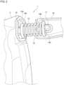
- Fig. 2 shows an example of the structure of the second connector 7.
- the second connector 7 is provided with a coil spring 12 as an elastic body provided between the main body 2 and the grip 3, and a guide rod 13 that maintains the direction of load on the coil spring 12 in alignment with the direction of the line of axis of the coil spring 12.
- the coil spring 12 is provided between the main body 2 and the grip 3 so as to be movable in coordination with the motion of the guide rod 13.
- the guide rod 13 has a role of aligning the direction of the line of axis of the coil spring 12 with the longitudinal direction of the guide rod 13.
- the upper part of the rear side of the main body 2 is provided with a cylindrical first rotation shaft 10 that extends in a transversal direction
- the front end of upper extension 3c is provided with a cylindrical second rotation shaft 11 that extends in a transversal direction.
- the main body 2 and the grip 3 are joined by the guide rod 13 so as to be rotatable relative to each other by inserting the first rotation shaft 10 into the first opening 13a of the guide rod 13 and inserting the second rotation shaft 11 into the second opening 13b of the guide rod 13.
- the second opening 13b is shaped such that the second rotation shaft 11 is slidable in the longitudinal direction of the guide rod 13.
- the second opening 13b is formed as an elongated through hole.
- the guide rod 13 is guided inside the coil spring 12 and is placed in alignment with the line of axis of the coil spring 12. This can make the second connector 7 compact.
- the guide rod 13 is provided with a first spring support 14a and a second spring support 14b.
- the coil spring 12 is supported by the first spring support 14a and the second spring support 14b.
- the first spring support 14a and the second spring support 14b have the same shape and will be referred to as "spring support 14" except when distinction is made.
- Fig. 4 shows an example of the spring support 14.
- the spring support 14 has a spring support surface 15a that the end of the coil spring 12 comes into contact with, a through hole 15b that the guide rod 13 is inserted through, and an annular rising portion 15c that rises from the outer circumference of the spring support surface 15a and prevents the lateral slip of the spring end.
- the first spring support 14a is thrust by the coil spring 12 to come into contact with the first rotation shaft 10
- the second spring support 14b is thrust by the coil spring 12 to come into contact with the second rotation shaft 11.
- Figs. 5 and 6 show the function of the vibration control structure.
- the vibration control structure when vibration or shock impact is generated in the main body 2 while the operator is using the tool, the vibration control structure causes the grip 3 to be rotated in the direction indicated by the arrow A around the first connector 5.
- the guide rod 13 transforms the rotational motion of the grip 3 into linear motion in the direction indicated by the arrow B, i.e., the longitudinal direction of the guide rod 13, by sliding the second rotation shaft 11 in the second opening 13b.
- Fig. 6 shows a state in which the grip 3 is rotated relative to the main body 2 so as to be relatively closer. In the process in which the grip 3 approaches the main body 2, the vibration is absorbed by the coil spring 12.
- Fig. 6 shows a state in which the second rotation shaft 11 moves in the second opening 13b so as to compress the coil spring 12.
- the guide rod 13 always transforms the rotational motion of the grip 3 into linear motion in the direction indicated by the arrow B. Therefore, the direction of load applied to the coil spring 12 moving in coordination with the guide rod 13 is maintained in the direction of the arrow B, i.e., the direction of the line of axis of the coil spring 12.
- the coil spring 12 is compressed or stretched in the presence of a load in the direction of the line of axis so that the spring constant is maintained constant during compression or extraction.
- the vibration control structure capable of providing linear vibration absorption function is realized. Since the coil spring 12 does not receive a load obliquely relative to the direction of the line of axis, the life of the spring can be extended without deteriorating the spring property of the coil spring 12.
- the above-described advantage of the vibration control structure will be appreciated more significantly when the electric power tool 1 is configured to be compact so that the interval between the first connector 5 and the second connector 7 is reduced.
- Fig. 7 shows an example of the structure of the first connector 5.
- the lower part of the housing rear side of the main body 2 is provided with a threaded groove.
- a screw member 18 is inserted through a spacer 17 provided in a through hole of the lower extension 3b and tightened to the main body 2 accordingly.
- the spacer 17 may be made of an elastic material. By configuring the spacer 17 to be elastic, the first connector 5 is provided with the function of absorbing vibration.
- the second connector 7 in which the guide rod 13 is inserted inside the coil spring 12 and the guide rod 13 and the coil spring 12 are integrated with each other is shown.
- the guide rod 13 and the coil spring 12 may be separate on the condition that the guide rod 13 maintains the direction of load on the coil spring 12 to in alignment with the direction of the line of axis of the coil spring 12.
- a plurality of guide rods 13 may be provided or a plurality of coil springs 12 may be provided. Where a plurality of coil springs 12 are provided, it is preferable that the coil springs 12 be arranged in the transversal direction.
- the first rotation shaft 10 is inserted in the first opening 13a of the guide rod 13, and the second rotation shaft 11 is inserted in the second opening 13b of the guide rod 13.
- the second rotation shaft 11 may be inserted in the first opening 13a and the first rotation shaft 10 may be inserted in the second opening 13b.
- the second opening 13b is formed as an elongated through hole.
- both the first opening 13a and the second opening 13b may be formed as elongated through holes.
- the coil spring 12 is shown as exemplifying an elastic body. A spring different from the coil spring 12 may be used as an elastic body. Still alternatively, a rubber body made of a resin material may be used.
Landscapes
- Engineering & Computer Science (AREA)
- Mechanical Engineering (AREA)
- Percussive Tools And Related Accessories (AREA)
- Portable Power Tools In General (AREA)
- Drilling And Boring (AREA)
Claims (5)
- Bohrhammer (1), aufweisend:einen Hauptkörper (2), der einen Motor und einen Bewegungsübertragungsmechanismus zum Übertragen einer Drehleistung des Motors an ein Vorderendwerkzeug (9) aufnimmt; undeinen Griff (3), der über einen ersten Verbinder (5) und einen zweiten Verbinder (7) an eine Rückseite des Hauptkörpers angefügt ist, wobeider erste Verbinder (5) den Hauptkörper (2) und den Griff (3) drehbar aneinanderfügt, undder zweite Verbinder (7) einen elastischen Körper (12), der zwischen dem Hauptkörper (2) und dem Griff (3) vorgesehen ist, sowie eine Führungsstange (13) aufweist,wobei die Führungsstange (13) ins Innere des elastischen Körpers (12) eingeführt ist und eine Richtung einer Belastung auf den elastischen Körper (12) in Ausrichtung mit einer Richtung einer Linie einer Achse des elastischen Körpers (12) aufrechterhält, undein Paar von Federstützen (14a, 14b), die jeweils eine Federstützfläche (15a) aufweisen, die Enden des elastischen Körpers (12) stützt,dadurch gekennzeichnet, dass:die Führungsstange (13) eine erste Öffnung (13a), in die eine erste Drehwelle (10) des Hauptkörpers (2) eingeführt ist, und eine zweite Öffnung (13b), in die eine zweite Drehwelle (11) des Griffs (3) eingeführt ist, aufweist, und die erste Öffnung (13a) oder die zweite Öffnung (13b) derart geformt ist, dass die erste Drehwelle (10) oder die zweite Drehwelle (11) in einer Längsrichtung der Führungsstange (3) verschiebbar ist, wobei die Führungsstange (13) ins Innere des elastischen Körpers (12) eingeführt ist und eine Richtung einer Belastung auf den elastischen Körper (12) in Ausrichtung mit einer Richtung einer Linie einer Achse des elastischen Körpers (13) aufrechterhält, unddass jede der Federstützen (14a, 14b) ein Durchgangsloch (15b) aufweist, durch das die Führungsstange (13) eingeführt ist.
- Bohrhammer nach Anspruch 2, wobei
die erste Öffnung (13a) oder die zweite Öffnung (13b) eine Form eines Langlochs aufweist, welches sich in der Längsrichtung der Führungsstange erstreckt. - Bohrhammer nach Anspruch 1 oder 2, wobei der elastische Körper eine Spiralfeder (12) ist.
- Bohrhammer nach einem der Ansprüche 1 bis 3, wobei
jede der Federstützen (14a, 14b) einen aufsteigenden Abschnitt (15c) aufweist, der von einem Außenumfang der Federstützfläche (15a) ansteigt und seitliches Verrutschen des Endes der Spiralfeder (12) verhindert. - Bohrhammer nach einem der Ansprüche 1 bis 4, wobei
das Paar Federstützen (14a, 14b) an Oberflächen, die den jeweiligen Federstützflächen (15a) gegenüberliegen, mit der ersten Drehwelle (10) bzw. der zweiten Drehwelle (11) in Kontakt kommt.
Applications Claiming Priority (1)
| Application Number | Priority Date | Filing Date | Title |
|---|---|---|---|
| JP2017050309A JP7001953B2 (ja) | 2017-03-15 | 2017-03-15 | ハンマドリル |
Publications (2)
| Publication Number | Publication Date |
|---|---|
| EP3375573A1 EP3375573A1 (de) | 2018-09-19 |
| EP3375573B1 true EP3375573B1 (de) | 2023-08-02 |
Family
ID=61256645
Family Applications (1)
| Application Number | Title | Priority Date | Filing Date |
|---|---|---|---|
| EP18157794.1A Active EP3375573B1 (de) | 2017-03-15 | 2018-02-21 | Bohrhammer |
Country Status (2)
| Country | Link |
|---|---|
| EP (1) | EP3375573B1 (de) |
| JP (1) | JP7001953B2 (de) |
Families Citing this family (6)
| Publication number | Priority date | Publication date | Assignee | Title |
|---|---|---|---|---|
| JP7268395B2 (ja) * | 2019-02-25 | 2023-05-08 | 工機ホールディングス株式会社 | 打込機 |
| CN216442260U (zh) | 2019-06-12 | 2022-05-06 | 米沃奇电动工具公司 | 电动工具 |
| CN113993667B (zh) * | 2019-06-13 | 2025-03-07 | 工机控股株式会社 | 电动作业机 |
| EP3990225A1 (de) * | 2019-06-26 | 2022-05-04 | Rhefor GbR | Handgeführtes setzgerät |
| JP7574634B2 (ja) * | 2020-12-15 | 2024-10-29 | 工機ホールディングス株式会社 | 作業機及び作業機の製造方法 |
| KR102576453B1 (ko) * | 2021-10-01 | 2023-09-12 | 계양전기 주식회사 | 전동공구의 충격완충장치 |
Citations (2)
| Publication number | Priority date | Publication date | Assignee | Title |
|---|---|---|---|---|
| JP2002096690A (ja) * | 2000-09-25 | 2002-04-02 | Sony Corp | リトラクト装置 |
| JP2017013173A (ja) * | 2015-06-30 | 2017-01-19 | 日立工機株式会社 | 動力作業機 |
Family Cites Families (5)
| Publication number | Priority date | Publication date | Assignee | Title |
|---|---|---|---|---|
| DE3312195A1 (de) * | 1983-04-02 | 1984-10-11 | Wacker-Werke Gmbh & Co Kg, 8077 Reichertshofen | Handgefuehrter schlag- und bohrhammer |
| DE4124574A1 (de) * | 1991-07-24 | 1993-01-28 | Wolf Woco & Co Franz J | Griffisolierung |
| DE10236135B4 (de) | 2002-08-07 | 2009-06-10 | Aeg Electric Tools Gmbh | Tragbares, handgeführtes Werkzeug |
| JP5180697B2 (ja) | 2008-06-19 | 2013-04-10 | 株式会社マキタ | 手持式作業工具 |
| US8966773B2 (en) | 2012-07-06 | 2015-03-03 | Techtronic Power Tools Technology Limited | Power tool including an anti-vibration handle |
-
2017
- 2017-03-15 JP JP2017050309A patent/JP7001953B2/ja active Active
-
2018
- 2018-02-21 EP EP18157794.1A patent/EP3375573B1/de active Active
Patent Citations (2)
| Publication number | Priority date | Publication date | Assignee | Title |
|---|---|---|---|---|
| JP2002096690A (ja) * | 2000-09-25 | 2002-04-02 | Sony Corp | リトラクト装置 |
| JP2017013173A (ja) * | 2015-06-30 | 2017-01-19 | 日立工機株式会社 | 動力作業機 |
Also Published As
| Publication number | Publication date |
|---|---|
| JP7001953B2 (ja) | 2022-01-20 |
| EP3375573A1 (de) | 2018-09-19 |
| JP2018153876A (ja) | 2018-10-04 |
Similar Documents
| Publication | Publication Date | Title |
|---|---|---|
| EP3375573B1 (de) | Bohrhammer | |
| EP3568253B1 (de) | Säge mit hin und her gehendem sägeblatt | |
| CA1170865A (en) | Motorized hand tool for drilling | |
| EP2415562B1 (de) | Hinterer Griff | |
| EP2090393B1 (de) | Elektrisches Kolbenwerkzeug | |
| EP3778085B1 (de) | Säbelsägeblattbefestigungsvorrichtung und säbelsäge | |
| EP2551060B1 (de) | Elektrowerkzeug | |
| US8104544B2 (en) | Hand machine tool | |
| US8893819B2 (en) | Hand-held power tool | |
| KR101590216B1 (ko) | 연삭 및 이와 유사한 공정을 위한 휴대용 기계장치 | |
| EP3381619A1 (de) | Hin- und hergehende arbeitsmaschine | |
| EP2415563B1 (de) | Schlagwerkzeug | |
| JPWO2020031888A1 (ja) | 電動工具 | |
| GB0325638D0 (en) | Vibration reduction apparatus for power tool and power tool incorporating such apparatus | |
| EP1693281B1 (de) | Motor betriebene Servo-Lenkvorrichtung | |
| US20120299254A1 (en) | Stroke shortening adapter for reciprocating power tool | |
| CN105710440A (zh) | 往复式电动工具 | |
| US10632605B2 (en) | Work tool | |
| EP3237137B1 (de) | Treibriemeneinstellung für einen elektroschneider | |
| CN104602866B (zh) | 工具机系统 | |
| JP2733075B2 (ja) | レシプロソー | |
| KR20120001182A (ko) | 전동톱 | |
| GB2533985A (en) | Rack guide mechanism | |
| CN117656009A (zh) | 具有机械式旋转冲击机构的手持式工具机 | |
| US9259817B2 (en) | Tool clamping fixture |
Legal Events
| Date | Code | Title | Description |
|---|---|---|---|
| PUAI | Public reference made under article 153(3) epc to a published international application that has entered the european phase |
Free format text: ORIGINAL CODE: 0009012 |
|
| STAA | Information on the status of an ep patent application or granted ep patent |
Free format text: STATUS: REQUEST FOR EXAMINATION WAS MADE |
|
| 17P | Request for examination filed |
Effective date: 20180221 |
|
| AK | Designated contracting states |
Kind code of ref document: A1 Designated state(s): AL AT BE BG CH CY CZ DE DK EE ES FI FR GB GR HR HU IE IS IT LI LT LU LV MC MK MT NL NO PL PT RO RS SE SI SK SM TR |
|
| AX | Request for extension of the european patent |
Extension state: BA ME |
|
| STAA | Information on the status of an ep patent application or granted ep patent |
Free format text: STATUS: EXAMINATION IS IN PROGRESS |
|
| 17Q | First examination report despatched |
Effective date: 20210526 |
|
| GRAP | Despatch of communication of intention to grant a patent |
Free format text: ORIGINAL CODE: EPIDOSNIGR1 |
|
| STAA | Information on the status of an ep patent application or granted ep patent |
Free format text: STATUS: GRANT OF PATENT IS INTENDED |
|
| INTG | Intention to grant announced |
Effective date: 20230301 |
|
| GRAS | Grant fee paid |
Free format text: ORIGINAL CODE: EPIDOSNIGR3 |
|
| GRAA | (expected) grant |
Free format text: ORIGINAL CODE: 0009210 |
|
| STAA | Information on the status of an ep patent application or granted ep patent |
Free format text: STATUS: THE PATENT HAS BEEN GRANTED |
|
| AK | Designated contracting states |
Kind code of ref document: B1 Designated state(s): AL AT BE BG CH CY CZ DE DK EE ES FI FR GB GR HR HU IE IS IT LI LT LU LV MC MK MT NL NO PL PT RO RS SE SI SK SM TR |
|
| REG | Reference to a national code |
Ref country code: GB Ref legal event code: FG4D |
|
| REG | Reference to a national code |
Ref country code: CH Ref legal event code: EP |
|
| REG | Reference to a national code |
Ref country code: DE Ref legal event code: R096 Ref document number: 602018054378 Country of ref document: DE |
|
| REG | Reference to a national code |
Ref country code: IE Ref legal event code: FG4D |
|
| REG | Reference to a national code |
Ref country code: LT Ref legal event code: MG9D |
|
| REG | Reference to a national code |
Ref country code: NL Ref legal event code: MP Effective date: 20230802 |
|
| REG | Reference to a national code |
Ref country code: AT Ref legal event code: MK05 Ref document number: 1594145 Country of ref document: AT Kind code of ref document: T Effective date: 20230802 |
|
| PG25 | Lapsed in a contracting state [announced via postgrant information from national office to epo] |
Ref country code: GR Free format text: LAPSE BECAUSE OF FAILURE TO SUBMIT A TRANSLATION OF THE DESCRIPTION OR TO PAY THE FEE WITHIN THE PRESCRIBED TIME-LIMIT Effective date: 20231103 |
|
| PG25 | Lapsed in a contracting state [announced via postgrant information from national office to epo] |
Ref country code: IS Free format text: LAPSE BECAUSE OF FAILURE TO SUBMIT A TRANSLATION OF THE DESCRIPTION OR TO PAY THE FEE WITHIN THE PRESCRIBED TIME-LIMIT Effective date: 20231202 |
|
| PG25 | Lapsed in a contracting state [announced via postgrant information from national office to epo] |
Ref country code: SE Free format text: LAPSE BECAUSE OF FAILURE TO SUBMIT A TRANSLATION OF THE DESCRIPTION OR TO PAY THE FEE WITHIN THE PRESCRIBED TIME-LIMIT Effective date: 20230802 Ref country code: RS Free format text: LAPSE BECAUSE OF FAILURE TO SUBMIT A TRANSLATION OF THE DESCRIPTION OR TO PAY THE FEE WITHIN THE PRESCRIBED TIME-LIMIT Effective date: 20230802 Ref country code: PT Free format text: LAPSE BECAUSE OF FAILURE TO SUBMIT A TRANSLATION OF THE DESCRIPTION OR TO PAY THE FEE WITHIN THE PRESCRIBED TIME-LIMIT Effective date: 20231204 Ref country code: NO Free format text: LAPSE BECAUSE OF FAILURE TO SUBMIT A TRANSLATION OF THE DESCRIPTION OR TO PAY THE FEE WITHIN THE PRESCRIBED TIME-LIMIT Effective date: 20231102 Ref country code: NL Free format text: LAPSE BECAUSE OF FAILURE TO SUBMIT A TRANSLATION OF THE DESCRIPTION OR TO PAY THE FEE WITHIN THE PRESCRIBED TIME-LIMIT Effective date: 20230802 Ref country code: LV Free format text: LAPSE BECAUSE OF FAILURE TO SUBMIT A TRANSLATION OF THE DESCRIPTION OR TO PAY THE FEE WITHIN THE PRESCRIBED TIME-LIMIT Effective date: 20230802 Ref country code: LT Free format text: LAPSE BECAUSE OF FAILURE TO SUBMIT A TRANSLATION OF THE DESCRIPTION OR TO PAY THE FEE WITHIN THE PRESCRIBED TIME-LIMIT Effective date: 20230802 Ref country code: IS Free format text: LAPSE BECAUSE OF FAILURE TO SUBMIT A TRANSLATION OF THE DESCRIPTION OR TO PAY THE FEE WITHIN THE PRESCRIBED TIME-LIMIT Effective date: 20231202 Ref country code: HR Free format text: LAPSE BECAUSE OF FAILURE TO SUBMIT A TRANSLATION OF THE DESCRIPTION OR TO PAY THE FEE WITHIN THE PRESCRIBED TIME-LIMIT Effective date: 20230802 Ref country code: GR Free format text: LAPSE BECAUSE OF FAILURE TO SUBMIT A TRANSLATION OF THE DESCRIPTION OR TO PAY THE FEE WITHIN THE PRESCRIBED TIME-LIMIT Effective date: 20231103 Ref country code: FI Free format text: LAPSE BECAUSE OF FAILURE TO SUBMIT A TRANSLATION OF THE DESCRIPTION OR TO PAY THE FEE WITHIN THE PRESCRIBED TIME-LIMIT Effective date: 20230802 Ref country code: AT Free format text: LAPSE BECAUSE OF FAILURE TO SUBMIT A TRANSLATION OF THE DESCRIPTION OR TO PAY THE FEE WITHIN THE PRESCRIBED TIME-LIMIT Effective date: 20230802 |
|
| PG25 | Lapsed in a contracting state [announced via postgrant information from national office to epo] |
Ref country code: PL Free format text: LAPSE BECAUSE OF FAILURE TO SUBMIT A TRANSLATION OF THE DESCRIPTION OR TO PAY THE FEE WITHIN THE PRESCRIBED TIME-LIMIT Effective date: 20230802 |
|
| PG25 | Lapsed in a contracting state [announced via postgrant information from national office to epo] |
Ref country code: ES Free format text: LAPSE BECAUSE OF FAILURE TO SUBMIT A TRANSLATION OF THE DESCRIPTION OR TO PAY THE FEE WITHIN THE PRESCRIBED TIME-LIMIT Effective date: 20230802 |
|
| PG25 | Lapsed in a contracting state [announced via postgrant information from national office to epo] |
Ref country code: SM Free format text: LAPSE BECAUSE OF FAILURE TO SUBMIT A TRANSLATION OF THE DESCRIPTION OR TO PAY THE FEE WITHIN THE PRESCRIBED TIME-LIMIT Effective date: 20230802 Ref country code: RO Free format text: LAPSE BECAUSE OF FAILURE TO SUBMIT A TRANSLATION OF THE DESCRIPTION OR TO PAY THE FEE WITHIN THE PRESCRIBED TIME-LIMIT Effective date: 20230802 Ref country code: ES Free format text: LAPSE BECAUSE OF FAILURE TO SUBMIT A TRANSLATION OF THE DESCRIPTION OR TO PAY THE FEE WITHIN THE PRESCRIBED TIME-LIMIT Effective date: 20230802 Ref country code: EE Free format text: LAPSE BECAUSE OF FAILURE TO SUBMIT A TRANSLATION OF THE DESCRIPTION OR TO PAY THE FEE WITHIN THE PRESCRIBED TIME-LIMIT Effective date: 20230802 Ref country code: DK Free format text: LAPSE BECAUSE OF FAILURE TO SUBMIT A TRANSLATION OF THE DESCRIPTION OR TO PAY THE FEE WITHIN THE PRESCRIBED TIME-LIMIT Effective date: 20230802 Ref country code: CZ Free format text: LAPSE BECAUSE OF FAILURE TO SUBMIT A TRANSLATION OF THE DESCRIPTION OR TO PAY THE FEE WITHIN THE PRESCRIBED TIME-LIMIT Effective date: 20230802 Ref country code: SK Free format text: LAPSE BECAUSE OF FAILURE TO SUBMIT A TRANSLATION OF THE DESCRIPTION OR TO PAY THE FEE WITHIN THE PRESCRIBED TIME-LIMIT Effective date: 20230802 |
|
| REG | Reference to a national code |
Ref country code: DE Ref legal event code: R097 Ref document number: 602018054378 Country of ref document: DE |
|
| PG25 | Lapsed in a contracting state [announced via postgrant information from national office to epo] |
Ref country code: IT Free format text: LAPSE BECAUSE OF FAILURE TO SUBMIT A TRANSLATION OF THE DESCRIPTION OR TO PAY THE FEE WITHIN THE PRESCRIBED TIME-LIMIT Effective date: 20230802 |
|
| PLBE | No opposition filed within time limit |
Free format text: ORIGINAL CODE: 0009261 |
|
| STAA | Information on the status of an ep patent application or granted ep patent |
Free format text: STATUS: NO OPPOSITION FILED WITHIN TIME LIMIT |
|
| 26N | No opposition filed |
Effective date: 20240503 |
|
| PG25 | Lapsed in a contracting state [announced via postgrant information from national office to epo] |
Ref country code: SI Free format text: LAPSE BECAUSE OF FAILURE TO SUBMIT A TRANSLATION OF THE DESCRIPTION OR TO PAY THE FEE WITHIN THE PRESCRIBED TIME-LIMIT Effective date: 20230802 |
|
| PG25 | Lapsed in a contracting state [announced via postgrant information from national office to epo] |
Ref country code: MC Free format text: LAPSE BECAUSE OF FAILURE TO SUBMIT A TRANSLATION OF THE DESCRIPTION OR TO PAY THE FEE WITHIN THE PRESCRIBED TIME-LIMIT Effective date: 20230802 |
|
| REG | Reference to a national code |
Ref country code: CH Ref legal event code: PL |
|
| PG25 | Lapsed in a contracting state [announced via postgrant information from national office to epo] |
Ref country code: LU Free format text: LAPSE BECAUSE OF NON-PAYMENT OF DUE FEES Effective date: 20240221 |
|
| PG25 | Lapsed in a contracting state [announced via postgrant information from national office to epo] |
Ref country code: CH Free format text: LAPSE BECAUSE OF NON-PAYMENT OF DUE FEES Effective date: 20240229 |
|
| GBPC | Gb: european patent ceased through non-payment of renewal fee |
Effective date: 20240221 |
|
| PG25 | Lapsed in a contracting state [announced via postgrant information from national office to epo] |
Ref country code: LU Free format text: LAPSE BECAUSE OF NON-PAYMENT OF DUE FEES Effective date: 20240221 Ref country code: CH Free format text: LAPSE BECAUSE OF NON-PAYMENT OF DUE FEES Effective date: 20240229 |
|
| PG25 | Lapsed in a contracting state [announced via postgrant information from national office to epo] |
Ref country code: BG Free format text: LAPSE BECAUSE OF FAILURE TO SUBMIT A TRANSLATION OF THE DESCRIPTION OR TO PAY THE FEE WITHIN THE PRESCRIBED TIME-LIMIT Effective date: 20230802 |
|
| PG25 | Lapsed in a contracting state [announced via postgrant information from national office to epo] |
Ref country code: BG Free format text: LAPSE BECAUSE OF FAILURE TO SUBMIT A TRANSLATION OF THE DESCRIPTION OR TO PAY THE FEE WITHIN THE PRESCRIBED TIME-LIMIT Effective date: 20230802 |
|
| REG | Reference to a national code |
Ref country code: BE Ref legal event code: MM Effective date: 20240229 |
|
| PG25 | Lapsed in a contracting state [announced via postgrant information from national office to epo] |
Ref country code: BE Free format text: LAPSE BECAUSE OF NON-PAYMENT OF DUE FEES Effective date: 20240229 |
|
| PG25 | Lapsed in a contracting state [announced via postgrant information from national office to epo] |
Ref country code: GB Free format text: LAPSE BECAUSE OF NON-PAYMENT OF DUE FEES Effective date: 20240221 |
|
| PG25 | Lapsed in a contracting state [announced via postgrant information from national office to epo] |
Ref country code: FR Free format text: LAPSE BECAUSE OF NON-PAYMENT OF DUE FEES Effective date: 20240229 |
|
| PG25 | Lapsed in a contracting state [announced via postgrant information from national office to epo] |
Ref country code: IE Free format text: LAPSE BECAUSE OF NON-PAYMENT OF DUE FEES Effective date: 20240221 |
|
| PG25 | Lapsed in a contracting state [announced via postgrant information from national office to epo] |
Ref country code: IE Free format text: LAPSE BECAUSE OF NON-PAYMENT OF DUE FEES Effective date: 20240221 Ref country code: GB Free format text: LAPSE BECAUSE OF NON-PAYMENT OF DUE FEES Effective date: 20240221 Ref country code: FR Free format text: LAPSE BECAUSE OF NON-PAYMENT OF DUE FEES Effective date: 20240229 Ref country code: BE Free format text: LAPSE BECAUSE OF NON-PAYMENT OF DUE FEES Effective date: 20240229 |
|
| PGFP | Annual fee paid to national office [announced via postgrant information from national office to epo] |
Ref country code: DE Payment date: 20250218 Year of fee payment: 8 |
|
| PG25 | Lapsed in a contracting state [announced via postgrant information from national office to epo] |
Ref country code: CY Free format text: LAPSE BECAUSE OF FAILURE TO SUBMIT A TRANSLATION OF THE DESCRIPTION OR TO PAY THE FEE WITHIN THE PRESCRIBED TIME-LIMIT; INVALID AB INITIO Effective date: 20180221 |
|
| PG25 | Lapsed in a contracting state [announced via postgrant information from national office to epo] |
Ref country code: HU Free format text: LAPSE BECAUSE OF FAILURE TO SUBMIT A TRANSLATION OF THE DESCRIPTION OR TO PAY THE FEE WITHIN THE PRESCRIBED TIME-LIMIT; INVALID AB INITIO Effective date: 20180221 |
|
| PG25 | Lapsed in a contracting state [announced via postgrant information from national office to epo] |
Ref country code: TR Free format text: LAPSE BECAUSE OF FAILURE TO SUBMIT A TRANSLATION OF THE DESCRIPTION OR TO PAY THE FEE WITHIN THE PRESCRIBED TIME-LIMIT Effective date: 20230802 |