EP3377163B1 - Drehmomentspule und verfahren - Google Patents
Drehmomentspule und verfahren Download PDFInfo
- Publication number
- EP3377163B1 EP3377163B1 EP15808492.1A EP15808492A EP3377163B1 EP 3377163 B1 EP3377163 B1 EP 3377163B1 EP 15808492 A EP15808492 A EP 15808492A EP 3377163 B1 EP3377163 B1 EP 3377163B1
- Authority
- EP
- European Patent Office
- Prior art keywords
- wire layer
- wire
- section
- torque coil
- layers
- Prior art date
- Legal status (The legal status is an assumption and is not a legal conclusion. Google has not performed a legal analysis and makes no representation as to the accuracy of the status listed.)
- Active
Links
Images


Classifications
-
- A—HUMAN NECESSITIES
- A61—MEDICAL OR VETERINARY SCIENCE; HYGIENE
- A61M—DEVICES FOR INTRODUCING MEDIA INTO, OR ONTO, THE BODY; DEVICES FOR TRANSDUCING BODY MEDIA OR FOR TAKING MEDIA FROM THE BODY; DEVICES FOR PRODUCING OR ENDING SLEEP OR STUPOR
- A61M25/00—Catheters; Hollow probes
- A61M25/01—Introducing, guiding, advancing, emplacing or holding catheters
- A61M25/09—Guide wires
- A61M25/09016—Guide wires with mandrils
-
- A—HUMAN NECESSITIES
- A61—MEDICAL OR VETERINARY SCIENCE; HYGIENE
- A61B—DIAGNOSIS; SURGERY; IDENTIFICATION
- A61B5/00—Measuring for diagnostic purposes; Identification of persons
- A61B5/01—Measuring temperature of body parts ; Diagnostic temperature sensing, e.g. for malignant or inflamed tissue
-
- A—HUMAN NECESSITIES
- A61—MEDICAL OR VETERINARY SCIENCE; HYGIENE
- A61B—DIAGNOSIS; SURGERY; IDENTIFICATION
- A61B5/00—Measuring for diagnostic purposes; Identification of persons
- A61B5/02—Detecting, measuring or recording for evaluating the cardiovascular system, e.g. pulse, heart rate, blood pressure or blood flow
- A61B5/021—Measuring pressure in heart or blood vessels
- A61B5/0215—Measuring pressure in heart or blood vessels by means inserted into the body
- A61B5/02154—Measuring pressure in heart or blood vessels by means inserted into the body by optical transmission
-
- A—HUMAN NECESSITIES
- A61—MEDICAL OR VETERINARY SCIENCE; HYGIENE
- A61B—DIAGNOSIS; SURGERY; IDENTIFICATION
- A61B5/00—Measuring for diagnostic purposes; Identification of persons
- A61B5/68—Arrangements of detecting, measuring or recording means, e.g. sensors, in relation to patient
- A61B5/6846—Arrangements of detecting, measuring or recording means, e.g. sensors, in relation to patient specially adapted to be brought in contact with an internal body part, i.e. invasive
- A61B5/6847—Arrangements of detecting, measuring or recording means, e.g. sensors, in relation to patient specially adapted to be brought in contact with an internal body part, i.e. invasive mounted on an invasive device
- A61B5/6851—Guide wires
-
- A—HUMAN NECESSITIES
- A61—MEDICAL OR VETERINARY SCIENCE; HYGIENE
- A61M—DEVICES FOR INTRODUCING MEDIA INTO, OR ONTO, THE BODY; DEVICES FOR TRANSDUCING BODY MEDIA OR FOR TAKING MEDIA FROM THE BODY; DEVICES FOR PRODUCING OR ENDING SLEEP OR STUPOR
- A61M25/00—Catheters; Hollow probes
- A61M25/01—Introducing, guiding, advancing, emplacing or holding catheters
- A61M25/09—Guide wires
-
- F—MECHANICAL ENGINEERING; LIGHTING; HEATING; WEAPONS; BLASTING
- F16—ENGINEERING ELEMENTS AND UNITS; GENERAL MEASURES FOR PRODUCING AND MAINTAINING EFFECTIVE FUNCTIONING OF MACHINES OR INSTALLATIONS; THERMAL INSULATION IN GENERAL
- F16C—SHAFTS; FLEXIBLE SHAFTS; ELEMENTS OR CRANKSHAFT MECHANISMS; ROTARY BODIES OTHER THAN GEARING ELEMENTS; BEARINGS
- F16C1/00—Flexible shafts; Mechanical means for transmitting movement in a flexible sheathing
- F16C1/02—Flexible shafts; Mechanical means for transmitting movement in a flexible sheathing for conveying rotary movements
-
- A—HUMAN NECESSITIES
- A61—MEDICAL OR VETERINARY SCIENCE; HYGIENE
- A61B—DIAGNOSIS; SURGERY; IDENTIFICATION
- A61B34/00—Computer-aided surgery; Manipulators or robots specially adapted for use in surgery
- A61B34/20—Surgical navigation systems; Devices for tracking or guiding surgical instruments, e.g. for frameless stereotaxis
- A61B2034/2046—Tracking techniques
- A61B2034/2061—Tracking techniques using shape-sensors, e.g. fiber shape sensors with Bragg gratings
-
- A—HUMAN NECESSITIES
- A61—MEDICAL OR VETERINARY SCIENCE; HYGIENE
- A61M—DEVICES FOR INTRODUCING MEDIA INTO, OR ONTO, THE BODY; DEVICES FOR TRANSDUCING BODY MEDIA OR FOR TAKING MEDIA FROM THE BODY; DEVICES FOR PRODUCING OR ENDING SLEEP OR STUPOR
- A61M25/00—Catheters; Hollow probes
- A61M25/01—Introducing, guiding, advancing, emplacing or holding catheters
- A61M25/09—Guide wires
- A61M2025/09058—Basic structures of guide wires
- A61M2025/09083—Basic structures of guide wires having a coil around a core
- A61M2025/09091—Basic structures of guide wires having a coil around a core where a sheath surrounds the coil at the distal part
-
- A—HUMAN NECESSITIES
- A61—MEDICAL OR VETERINARY SCIENCE; HYGIENE
- A61M—DEVICES FOR INTRODUCING MEDIA INTO, OR ONTO, THE BODY; DEVICES FOR TRANSDUCING BODY MEDIA OR FOR TAKING MEDIA FROM THE BODY; DEVICES FOR PRODUCING OR ENDING SLEEP OR STUPOR
- A61M25/00—Catheters; Hollow probes
- A61M25/01—Introducing, guiding, advancing, emplacing or holding catheters
- A61M25/0102—Insertion or introduction using an inner stiffening member, e.g. stylet or push-rod
-
- A—HUMAN NECESSITIES
- A61—MEDICAL OR VETERINARY SCIENCE; HYGIENE
- A61N—ELECTROTHERAPY; MAGNETOTHERAPY; RADIATION THERAPY; ULTRASOUND THERAPY
- A61N1/00—Electrotherapy; Circuits therefor
- A61N1/02—Details
- A61N1/04—Electrodes
- A61N1/05—Electrodes for implantation or insertion into the body, e.g. heart electrode
- A61N1/056—Transvascular endocardial electrode systems
Definitions
- a coil includes a single wire that is tightly wound over itself to form a multi-layer coil with a hollow lumen.
- such coils use solder or brazing to secure ends of the coil to prevent its uncoiling. Because there are limitations to use of such approaches, there is a need for the present invention.
- US 2007/083132 A1 describes a medical device coil comprising a first coil and a second coil to which the first coil is affixed with affixation points.
- EP 0661072 A1 describes a catheter includes an inner layer, an outer layer, and an intermediate layer arranged between the inner and outer layers.
- US 5,103,543 A1 describes a torque transmitter includes three coaxial helically wound springs of different inner and outer diameters positioned relative to each other such that the inner a The torque transmitter has three coaxial, helically wound, flat springs, of different inner and outer diameters such that the centre spring is in an interference fit with both inner and outer springs. The springs are brazed or soldered together at each end, leaving a central bore open for catheters.
- One embodiment includes a torque coil according to claim 1.
- the torque coil also includes a core of a polymer material within the inner wire layer, such that the inner, intermediate and outer wire layers are secured between the core and the outer polymer cover. Securing the inner, intermediate and outer layers according to claim 1 allows the torque coil in some embodiments to be readily assembled and provide excellent one-to-one torque with very high flexibility.
- the torque coil includes polymer material from the core or polymer material from the outer polymer cover to penetrate between filars in at least one of the inner and outer wire layers. This provides stiffening of the torque coil in the areas of penetration.
- the torque coil includes an intermediate wire layer helically wound over the inner wire layer in a constricted state, the outer wire layer being helically wound over the intermediate wire layer. Additional intermediate layers provide additional stiffness and add further strength to the torque coil to prevent kinking and provide resistance to elongation, and has excellent compression resistance between adjacent filars.
- the torque coil includes a penetrated section where the polymer material of the outer polymer cover penetrates between adjacent filars in the outer wire layer in a of the torque coil and a non-penetrated section where the polymer material of the outer polymer cover does not significantly penetrate between adjacent filars in the outer wire layer in a of the torque coil.
- the torque coil accordingly has increased relative flexibility in the non-penetrated section and has decreased relative flexibility in the penetrated section, which is useful in many applications, such as within the vasculature of a human or animal.
- the torque coil includes a tight-wound section where at least one of the inner and outer wire layers is tight wound and an open-wound section where at least one of the inner and outer wire layers is open wound.
- the torque coil accordingly has increased relative flexibility in the open-wound section and has decreased relative flexibility in the tight-wound section, which is useful in many applications, such as within the vasculature of a human or animal.
- the torque coil includes a full-wire layer section where both the inner and outer wire layers are within the full-wire layer section and a partial-wire layer section where the outer wire layer is not within the partial-wire layer section.
- the torque coil accordingly has increased relative flexibility in the partial-wire layer section and has decreased relative flexibility in the full-wire layer section, which is useful in many applications, such as within the vasculature of a human or animal.
- the torque coil includes a pull wire is attached directly to at least one of the wire layers adjacent a distal end of the torque coil. This is useful in some applications that use a deflectable catheter and avoids the use of a pull ring, thereby saving expense and manufacturing time.
- the outer polymer cover of the torque coil secures the inner and outer layers without use of welding, brazing or soldering. This allows assemble of the toque coil without damaging a polymer core with heat from welding, brazing or soldering.
- the torque coil has a lumen diameter is between 0.008 inches and 0.220 inches, the diameter of the coil is between 0.01 inches and 0.250 inches, and the diameter of the wire is between 0.0005 inches and 0.004 inches.
- Such dimensions make the torque coil useful in many applications, such as catheter or related application within the vasculature of a human or animal.
- the torque coil includes a polymer core and an inner wire layer helically wound in a constricted state over the polymer core.
- An outer wire layer is helically wound over the inner wire layer in a constricted state.
- An outer polymer cover surrounds the inner and outer wire layers thereby securing the wire layers between the polymer core and the outer polymer cover. Securing the inner and outer wire layers in this way allows the torque coil in some embodiments to be readily assembled and provide excellent one-to-one torque with very high flexibility.
- the stiff section of the torque coil includes a section in which the polymer material of the outer polymer cover penetrates between adjacent filars in the outer wire layer in a of the torque coil or a section in which at least one of the inner and outer wire layers is tight wound or a section in which both the inner and the outer wire layer is contained within the flexible section.
- the flexible section of the torque coil includes a section in which the polymer material of the outer polymer cover does not significantly penetrate between adjacent filars in the outer wire layer in a of the torque coil, or a section in which at least one of the inner and outer wire layers is open wound, or a section wherein the outer wire layer is not within the flexible section.
- One embodiment includes a method of forming a torque coil according to claim 11.
- the method includes temporarily securing one of the inner and outer wire layers with a clamp until the outer polymer cover secures the inner and outer wire layers between the core and the outer polymer cover. This prevents the wire layers from unwinding and holds the constricted state. Because the wire layers remain constrained, there is no slippage between the wire layers, thereby providing the torque coil with excellent one-to-one torque.
- the method includes forming the outer polymer while controlling the polymer material of the outer polymer cover such that it penetrates between adjacent filars in the outer wire layer of the torque coil in a penetrated section and forming the outer polymer while controlling the polymer material of the outer polymer cover such that it does not significantly penetrate between adjacent filars in the outer wire layer in a of the torque coil in a non-penetrated section such that the torque coil has increased relative flexibility in the non-penetrated section and has decreased relative flexibility in the penetrated section, which is useful in many applications, such as within the vasculature of a human or animal.
- the method includes winding the inner or outer wire layer with a tight-wound section in which at least one of the inner and outer wire layers is tight wound and winding the inner or outer wire layer with an open-wound section in which at least one of the inner and outer wire layers is open wound, such that the torque coil has increased relative flexibility in the open-wound section and has decreased relative flexibility in the tight-wound section, which is useful in many applications, such as within the vasculature of a human or animal.
- the method includes winding the inner and outer wire layer with a full-wire layer section in which both the inner and outer wire layers are within the full-wire layer section and winding the inner and outer wire layer with a partial-wire layer section in which the outer wire layer is not within the partial-wire layer section, such that the torque coil has increased relative flexibility in the partial-wire layer section and has decreased relative flexibility in the full-wire layer section, which is useful in many applications, such as within the vasculature of a human or animal.
- FIG. 1a illustrates a partial cut-away perspective view of a helically-wound torque coil 10 in accordance with one embodiment.
- torque coil 10 includes a core 12, which in one embodiment is a layer of polymer material that is customizable to various applications, as will be further discussed below.
- torque coil 10 further includes an inner wire layer 14 helically wound over core 12 and an intermediate wire layer 16 helically wound over inner wire layer 14 (in the figure, a portion of intermediate wire layer 16 is cut away to show inner wire layer 14 below it).
- Torque coil 10 further includes an outer wire layer 18 helically wound over intermediate wire layer 16 (in the figure, a portion of outer wire layer 18 is cut away to show intermediate wire layer 16 below it).
- Outer polymer cover 20 is formed over the combination of core 12, inner wire layer 14, intermediate wire layer 16, and outer wire layer 18, thereby securing the combination together.
- inner wire layer 14 is tightly wound in a constricted state over core 12, and each subsequent wire layer, that is, intermediate wire layer 16, outer wire layer 18, etc., is tightly wound in a constricted state over the previous wire layer across the entire layer.
- a single wire filar is used for each of inner, intermediate and outer wire layers 14, 16 and 18 without ever being cut or interrupted. In this way, inner wire layer 14 is wound on core 12, and then intermediate wire layer 16 is wound back over inner wire layer 14 without ever cutting the wire that is used to wind the layers. The same can be done for outer wire layer 18 and for any additional intermediate wire layers.
- a wire is broken or cut between each adjacent wire layer, but because each wire layer is tightly wound in a constricted state, each immediately adjacent over wire layer, that is, the wire layer subsequently wound over the previous wire layer, constrains the previous wire layer and prevents its unwinding.
- Outer wire layer 18 in the embodiment of Figure 1a is then constrained by outer polymer cover 20, as is discussed further below. Because all wire layers are constrained, there is no slippage between the wire layers. In this way torque coil 10 has excellent "one-to-one" torque, that is, a single full rotation at one end of torque coil 10 results in a single full rotation at the opposite end, rather than something less than a full rotation.
- the illustrated embodiment in Figure 1 has three wire layers (14, 16, 18) between core 12 and outer polymer cover 20, using more than three layers are also possible for torque coil 10 by adding multiple additional intermediate layers.
- inner wire layer 14 is illustrated as helically wound with a pitch in a first direction, while intermediate wire layer 16 is helically wound with a pitch in a second direction that is reverse relative to the first direction.
- Outer wire layer 18 is then illustrated as helically wound with a pitch substantially in the first direction, similar to inner wire layer 14.
- Reverse winding in this way allows torque coil 10 to be used in rotating applications without collapsing in or winding open with the rotation of torque coil 10.
- Reverse winding provides additional stability to torque coil 10 for bi-directional rotational applications, such that it can be rotated in both clockwise and counterclockwise directions without collapsing in or winding open with the rotation. Such an embodiment may be useful in various rotational intravascular applications.
- torque coil 10 is extremely resistant to kinking and resistant to elongation and has excellent compression resistance between adjacent filars, such that it may be useful in intravascular applications requiring pushing, pulling and bending of torque coil 10. Despite these strengths and excellent bi-directional turning, torque coil 10 also has excellent flexibility.
- Figure 1b illustrates one embodiment of torque coil 10, including core 12, inner wire layer 14 wound over core 12, intermediate wire layer 16 wound over inner wire layer 14, outer wire layer 18 wound over intermediate wire layer 16 and outer polymer cover 20 formed over outer wire layer 18.
- mandrel 11 is provided within core 12.
- core 12 is a polymer layer that is provided over mandrel 11. Wire layers 14, 16 and 18 are then wound over core 12 as described above, each wire layer holding and constraining the prior wire layer. Outer polymer cover 20 is then formed over the prior wire layers. Because outer polymer cover is configured to sufficiently constrain the wire layers below it in some embodiments, once outer polymer cover 20 is in place, mandrel 11 can be removed. In such case, core 12 will have an inner lumen (such as that illustrated and discussed below in Figure 2c ) that can be filled or used in various applications as discussed.
- FIGS 2a-2c illustrate various embodiments of core 12 of torque coil 10.
- core 12 is readily adaptable for various applications.
- core 12 is a polymer layer that is configured with a plurality of lumens.
- core 12a illustrated in Figure 2a , includes a main lumen 22.
- Main lumen 22 can be configured, for example, to receive a guidewire, which is useful for placing torque coil 10 within the vasculature system of a human or animal.
- Peripheral lumens 24a-24d are provided in one embodiment adjacent each other and to the main lumen 22 for receiving sensing wires or other wire-like structures, for providing independent passage for fluids, or for other purposes.
- core 12 is readily formed by extruding, injection molding or the like, one skilled in the art understands that a variety of configurations, shapes and sizes of core 12 are available for torque coil 10.
- core 12b illustrated in Figure 2b is completely solid.
- Core 12c, illustrated in Figure 2c has a relatively thick perimeter section 28 defining a single lumen through its center.
- Various other examples and combinations are possible, such as having more lumens that are adjacent or coaxial.
- core 12 is rigid enough that it is capable of functioning as a mandrel and inner wire layer 14 is wound directly on to core 12, with the subsequent wire layers wound over inner wire layer 14.
- inner wire layer 14 can be wound over a more rigid mandrel 11 as discussed above, which can then be subsequently removed once all wire layers are sufficiently constrained, such as by outer polymer cover 20.
- the combination of core 12 and outer polymer cover 20 secure and hold wire layers 14, 16, 18 in place.
- torque coil 10 cannot use braze, solder, welding or fusing, however, since all of these methods of securing the layers include application of significant heat that can damage core 12 in some instances.
- welding or brazing wire layers 14, 16, 18 to secure them will also melt core 12 and damage its functionality, for example, by closing off of partially changing diameter of lumens 22, 24a, 24b, 24c, 24d.
- torque coil 10 coats the outer wire layer 18, in the illustrated example, with outer polymer cover 20.
- Outer polymer cover 20 can be any of a variety of biocompatible polymers that will secure wire layers 14, 16, 18 and prevent their unwinding, even when the wire layers of torque coil 10 are wound in a constricted state.
- Figures 3a-3b are sectional views illustrating wire layers 14, 16, 18 secured between core 12 and outer polymer cover 20.
- a polymer is flowed over wire layers 14, 16 and 18 and then allowed to solidify thereby forming outer polymer cover 20. Once solidified, outer polymer cover 20 has enough rigidity to prevent wire layers 14, 16 and 18 from unwinding.
- FIG 4 is an enlarged detailed section 4 shown in dotted lines in Figure 3b .
- each of wire layers 14, 16 and 18 are tightly wound over a preceding layer, that is, the wire filar used to wind each wire layer is helically wound such that each filar in a layer is immediately adjacent another filar on either side.
- outer wire layer 18 is helically wound with a single wire such that small spaces are left between adjacent filars 18a within outer layer 18.
- small amounts of material 21 from outer polymer cover 20 flow into these small spaces between adjacent filars 18a within outer wire layer 18. In one embodiment, this flow of material 21 can be controlled in order to improve the overall performance of torque coil 10.
- torque coil 10 it can be useful for torque coil 10 to have variable stiffness along its length.
- the melting of a polymer in forming outer polymer cover 20 can be controlled such that more material 21 penetrates into adjacent filars 18a within outer wire layer 18 in certain sections of length along torque coil 10, while in other section of length along coil 10 only small amounts or no material 21 penetrates into outer wire layer 18.
- some sections (non-penetrated) of torque coil 10 will be more flexible from the wire portions within wire layers 14, 16 and 18, while other sections (penetrated) of torque coil 10 will be stiffer where polymer material 21 is allowed to penetrate and limit motion of torque coil 10 within outer wire layer 18.
- torque coil 10 core 12 can also be formed from a polymer material, it too can be controlled such that material 13 from core 12 penetrates in between filars 14a of inner layer 14, thereby adding more stiffness to torque coil 10 in those areas, as also illustrated in Figure 4 .
- FIG. 5 illustrates a portion of torque coil 10, where wire layers 14, 16, and 18 are exploded apart, and core 12 and outer polymer cover 20 are removed. In the exploded view of the figure, wire layers 14, 16, and 18 are aligned so that open-wound section 30 is illustrated between the dotted lines.
- each of wire layers 14, 16, and 18 are "open wound” such that each filar within each wire layer 14, 16, and 18 is spaced apart from each adjacent filar.
- torque coil 10 is readily deflectable in open-wound section 30. This may be useful in certain applications, such as when torque coil 10 is used within the vascular system of a human or animal and needs to deflect within the tortuous path of the vasculature.
- torque coil 10 in Figure 5 is illustrated as "tight wound” such that each filar within each of wire layers 14, 16, and 18 are immediately adjacent each other filar on either side.
- torque coil 10 will have significantly less ability to deflect compared to that in open-wound section 30.
- This variable flexibility along the length of torque coil 10 is useful in some applications.
- the flexibility of open-wound section 30 can be useful for navigation, whereas the relatively stiffer portions outside open-wound section 30 are useful where high push and/or pull strength is needed. Further stiffening in these tight wound areas may be achieved with penetration of material into the layers as discussed above.
- Figures 6a-6d illustrate other embodiments of torque coil 10.
- wire layers 14, 16, and 18 layers each vary in length, thereby also varying the overall flexibility of torque coil 10 along its length.
- inner wire layer 14 is a wire helically wound over a core (not visible in Figures 6a-6b ) similarly to previously-described embodiments.
- Intermediate wire layer 16 is then wound over inner wire layer 14, but then terminated such that it covers less than the entire length of torque coil 10. Accordingly, there is a first partial wire layer section 42 of torque coil 10 in which only inner wire layer 14 is wound over core 12.
- some wire layers will be welded to the wire layer below.
- intermediate wire layer 16 may be welded to inner wire layer 14 at the interface between first and second partial wire layer sections 42 and 44.
- outer wire layer 18 may be welded to intermediate wire layer 16 at the interface between second partial wire layer section 44 and full-wire layer section 46.
- Figure 6b further illustrates outer polymer cover 20 over all of the wire layers of torque coil 10. Once fully assembled within outer polymer cover 20, torque coil 10 will have varied flexibility along its length. In first partial wire layer section 42, where only inner wire layer 14 is present, torque coil 10 will have more flexibility than in full-wire layer section 46, where all three layers 14, 16, and 18 are present. The second partial wire layer section 44 will have flexibility between that of first partial wire layer section 42 and full-wire layer section 46.
- Figures 6c-6d illustrate inner wire layer 14 is a wire helically wound over a core (not visible in Figures 6c-6d ) similarly to previously-described embodiments. Intermediate wire layer 16 is then wound over inner wire layer 14, but then terminated such that it covers less than the entire length of torque coil 10. Also in this section, outer wire layer 18 is wound over intermediate wire layer 16. Accordingly, there is a partial wire layer section 41 of torque coil 10 in which only inner wire layer 14 is wound over core 12. Also, there is a full-wire layer section 43 of torque coil 10 in which wire layers 14, 16 and 18 are all present. As in the previous embodiment, in some embodiments, partial wire layers will be welded to the wire layer below.
- outer wire layer 18 and intermediate wire layer 16 may be welded to inner wire layer 14 at the interface between partial wire layer section 41 and full-wire layer section 43.
- partial wire layer section 41 has greater flexibility than does full-wire layer section 43, where three wire layers are present.
- torque coil 10 in Figures 6a-6d are useful in many applications, including vascular applications, where it is helpful to have certain sections of the coil, for example the distal end, more flexible and have certain sections, for example the proximal end, more stiff.
- the configuration of torque coil 10 having sections of different numbers of wire layers as illustrated in Figure 6a-6d can also be combined with open-wound sections illustrated in Figure 5 and/or flowing material between adjacent filars illustrated in Figure 4 in order to create custom flexibility and stiffness.
- full-wire layer section 46 illustrated in Figure 6b material 21 from outer polymer cover 20 can be allowed to penetrate between filars 18a of third layer 18, as illustrated in Figure 4 .
- full-wire layer section 46 will have even greater relative stiffness than it would have without polymer material penetrating the filars.
- the filars of wire layers 14, 16, 18 can be open wound within second partial wire layer section 44 of Figure 6b so that second partial wire layer section 44 will have even greater relative flexibility.
- torque coil 10 can be further secured beyond the securing of layers between core 12 and outer polymer cover 20.
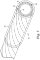
- Figure 7 illustrates an end view of a torque coil 10.
- Wire layers 14, 16 and 18 are helically wound over core 12 (not illustrated in Figure 7 ).
- Clamp 45 (illustrated as ghosted in Figure 7 ) is temporally placed over wire layers 14, 16 and 18 to prevent their unwinding. With clamp 45 in place the wire layers 14, 16 and 18 can be welded along their end surface 50. Once wire layers 14, 16 and 18 are secured along the end surface 50 with a weld, clamp 45 can be removed and an outer polymer cover 20 can be added.
- any welding along end surface 50 is limited to only the end surface 50 and is kept to a very limited duration so as to limit any heat damage to core 12. In one embodiment, the welding does not exceed 30 seconds. In other embodiments, end surface 50 is brazed, solder or the like in order to further secure the layers and prevent their unwinding.
- torque coil 10 is assembled one layer at a time.
- assembly of torque coil 10 begins with mandrel 11 (illustrate din Figure 1b .
- Core 12 is formed over mandrel 11 as a polymer layer using any of a variety of methods of forming polymers over a solid mandrel, such as injection molding, extruding, or the like.
- torque coil 10 can be formed without mandrel 11, and instead begins with forming core 12 (as in Figure 1a ).
- inner wire layer is wound directly over core 12 in a constrained state. If a single wire is used to form all wire layers within torque coil 10, then the winding of each subsequent layer will constrain each prior layer. For example, winding intermediate wire layer 16 over inner wire layer 14 constrains layer 14. If a wire is cut after winding inner wire layer 14, however, that layer 14 will need to be temporarily constrained until a new wire can be wound over it to form intermediate wire layer 16 over inner wire layer 14 constraining it. In such case, a clamp, such as clamp 45 illustrated in Figure 7 , or similar heat shrink or the like can be used to temporarily constrain inner layer 14 until intermediate wire layer 16 is fully wound over it.
- a clamp such as clamp 45 illustrated in Figure 7 , or similar heat shrink or the like can be used to temporarily constrain inner layer 14 until intermediate wire layer 16 is fully wound over it.
- outer wire layer 18 is constrained by outer polymer cover 20, which can be formed in a variety of ways, including injection molding, extruding or similar methods. Outer wire layer 18 can also be temporarily constrained by clamp, heat shrink or the like until outer polymer cover 20 is fully formed.
- torque coil 10 is configured for very small applications, such as for the vascular system of humans and animals.
- the wire in wire layers 14, 16 and 18 has a wire diameter (WD) as small as 0.0005 inches up to 0.004 inches.
- torque coil 10 has an inner diameter (ID) as small as 0.008 inches up to 0.220 inches, which also defines the diameter of the lumen within inner wire layer 14, and thus the outer diameter of core 12, for torque coil 10.
- the outer diameter (OD) of torque coil 10 is 0.01 inches and 0.250 inches. Different OD and ID sizes for torque coil 10 are also possible where various different size wire is used.
- the illustrations herein primarily show the wire that is used in wire layers 14, 16 and 18 as flat or rectangular, but other shapes can be used in accordance with other embodiments. For example, round wire or other shapes can be used.
- the wire in wire layers 14, 16 and 18 can be made from one or more of stainless steel, Nitinol ® , MP35N, titanium and tantalum.
- outer polymer cover 20 can be made from one or more of pebax, nylon, PET, FEP, and polyurenthane and core 12 can be made from one or more of polyimide, PTFE, pebax, nylon, polyurethane, HDPE, and PEEK.
- Wire layers 14, 16 and 18 can be wound in variety of ways according to embodiments.
- one convolution of wire is wound at one time for each of wire layers 14, 16 and 18.
- torque coil 10 is a multi-filar coil, where multiple convolutions of adjacent wire are wound at once. Two, three, four, five or more adjacent wire helices can be wound within each layer at one time.
- each of wire layers 14, 16 and 18 may be wound with a single wire filar, or each layer can be wound with strands of wire so that each layer has adjacent strands of wire.
- outer polymer cover 20 is retaining all layers against core 12 and there is no welding or brazing of the wire layers 14, 16, 18, end surfaces, such as end surface 50 in Figure 7 , are relatively clean and smooth areas. As such, other coils, cables and devices can be readily attached. Because torque coil 10 is thus free of any foreign material, such as braze or solder, which can complicate or weaken the attachment of devices, additional devices can readily be attached to torque coil 10 at its ends.
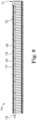
- Figure 8 illustrates a pull-ring catheter 60 in accordance with the prior art.
- Pull-ring catheter 60 includes outer jacket 62, inner jacket 64, pull ring 66, pull wire 68 and lumen 70.
- Deflectable catheters like pull-ring catheter 60 feature a distal tip that can be pulled into a defined curve. This is achieved by using a wire 68 connected to a pull ring 66 near the tip of catheter 60. The distal tip returns to its original shape through natural springback of pull-ring catheter 60.
- outer jacket 62 is partially cut away in the illustration to show the components below, when fully assembled outer jacket 62 covers pull ring 66 thereby securing ring 66 between outer and inner jackets 62 and 64. Furthermore, pull ring 66 also includes opening 72 such that the material of inner jacket 64 flows through opening 72 further securing ring 66 in place. Wire 68 is fixed to ring 66 via a weld or similar means and then fed back to the proximal end of catheter 60 in lumen 70, which extends through outer jacket 62.
- FIG. 9 illustrates torque coil catheter 110 in accordance with one embodiment. Similar to torque coil 10 described above, torque coil catheter 110 can includes a core, but is illustrated without a core for ease of description. Torque coil catheter 110 includes an inner wire layer 114 helically wound over core 12. Additional wire layers 116 and 118 are wound over inner wire layer 114 as described above. Outer polymer cover 120 surrounds wire layers 114, 116 and 118. Torque coil catheter 110 further includes pull wire 115 extending between its proximal and distal ends.
- a small section or groove is made in wire layers 114, 116 and 118 at the distal end of torque coil catheter 110 at connection zone 111. Because wire layers 114, 116 and 118 are typically metal wire, pull wire 115 is readily connectable directly to wire layers 114, 116 and 118 at connection zone 111 via welding or the like. In another embodiment, pull wire 115 can be terminated just short of the distal end, such as two or three inches short of the distal end, and welded, glued or otherwise attached directly to the inner diameter of inner wire layer 114 at alternate connection zone 121.
- pull wire 115 can then be pulled at the proximal end of torque coil catheter 110 to deflect the distal end. Because the entire inner wire layer 114 is typically metal wire, pull wire 115 can be easily connected to any location of the distal end of torque coil catheter 110. Unlike prior systems, no additional pull ring part is necessary allowing both the savings of the cost of the part and its assembly to the catheter.
Landscapes
- Health & Medical Sciences (AREA)
- Life Sciences & Earth Sciences (AREA)
- Engineering & Computer Science (AREA)
- Veterinary Medicine (AREA)
- General Health & Medical Sciences (AREA)
- Biophysics (AREA)
- Biomedical Technology (AREA)
- Heart & Thoracic Surgery (AREA)
- Public Health (AREA)
- Animal Behavior & Ethology (AREA)
- General Engineering & Computer Science (AREA)
- Surgery (AREA)
- Medical Informatics (AREA)
- Pathology (AREA)
- Physics & Mathematics (AREA)
- Molecular Biology (AREA)
- Hematology (AREA)
- Pulmonology (AREA)
- Anesthesiology (AREA)
- Cardiology (AREA)
- Mechanical Engineering (AREA)
- Oral & Maxillofacial Surgery (AREA)
- Physiology (AREA)
- Vascular Medicine (AREA)
- Media Introduction/Drainage Providing Device (AREA)
Claims (15)
- Drehmomentspule (10), umfassend:eine innere Drahtschicht (14, 114), die in einem verengten Zustand spiralförmig gewickelt ist;eine mittlere Drahtschicht (16), die in einem verengten Zustand spiralförmig über die innere Drahtschicht gewickelt isteine äußere Drahtschicht (18), die in einem verengten Zustand spiralförmig über die innere und die mittlere Drahtschicht gewickelt ist; undeine äußere Polymerabdeckung (20, 120), die die innere, mittlere und äußere Drahtschicht umgibt, wodurch die Drahtschichten innerhalb der äußeren Polymerabdeckung befestigt werden;dadurch gekennzeichnet, dass die äußere Polymerabdeckung die innere, mittlere und äußere Schicht ohne Verwendung von Schweißen, Hartlöten oder Löten befestigt.
- Drehmomentspule nach Anspruch 1, ferner umfassend einen Kern (12) eines Polymermaterials innerhalb der inneren Drahtschicht, sodass die innere und äußere Drahtschicht zwischen dem Kern und der äußeren Polymerabdeckung befestigt sind.
- Drehmomentspule nach Anspruch 2, wobei mindestens eines von Polymermaterial aus dem Kern und Polymermaterial aus der äußeren Polymerabdeckung zwischen Filamenten in mindestens einer der inneren und äußeren Drahtschicht durchdringt.
- Drehmomentspule nach Anspruch 1, ferner umfassend:einen durchdrungenen Abschnitt, wobei das Polymermaterial der äußeren Polymerabdeckung zwischen benachbarten Filamenten in der äußeren Drahtschicht in einer der Drehmomentspule durchdringt; undeinen nicht-durchdrungenen Abschnitt, wobei das Polymermaterial der äußeren Polymerabdeckung zwischen benachbarten Filamenten in der äußeren Drahtschicht in einer der Drehmomentspule nicht wesentlich durchdringt;wobei die Drehmomentspule eine erhöhte relative Flexibilität in dem nicht-durchdrungenen Abschnitt aufweist und eine verringerte relative Flexibilität in dem durchdrungenen Abschnitt aufweist.
- Drehmomentspule nach Anspruch 1, ferner umfassend:einen fest gewickelten Abschnitt, wobei mindestens eine der inneren und äußeren Drahtschicht fest gewickelt ist; undeinen offen gewickelten Abschnitt, wobei mindestens eine der inneren und äußeren Drahtschicht offen gewickelt ist;wobei die Drehmomentspule eine erhöhte relative Flexibilität in dem offen gewickelten Abschnitt aufweist und eine verringerte relative Flexibilität in dem fest gewickelten Abschnitt aufweist.
- Drehmomentspule nach Anspruch 1, ferner umfassend:einen Volldrahtschichtabschnitt (43, 46), wobei sowohl die innere als auch die äußere Drahtschicht sich innerhalb des Volldrahtschichtabschnitts befinden; undeinen Teildrahtschichtabschnitt, wobei sich die äußere Drahtschicht nicht innerhalb des Teildrahtschichtabschnitts befindet;wobei die Drehmomentspule eine erhöhte relative Flexibilität in dem Teildrahtschichtabschnitt aufweist und eine verringerte relative Flexibilität in dem Volldrahtschichtabschnitt aufweist.
- Drehmomentspule nach Anspruch 1, wobei ein Zugdraht (68) direkt an mindestens einer der Drahtschichten benachbart an ein distales Ende der Drehmomentspule angebracht ist.
- Drehmomentspule nach Anspruch 1, wobei die Spule für eine Hochgeschwindigkeitsdrehung und ein Eins-zu-Eins-Drehmoment konfiguriert ist.
- Drehmomentspule nach Anspruch 1, wobei der Lumendurchmesser zwischen 0,20 mm (0,008 Zoll) und 5,58 mm (0,220 Zoll) beträgt,
der Durchmesser der Spule zwischen 0,254 mm (0,01 Zoll) und 6,35 mm (0,250 Zoll) beträgt und der Durchmesser des Drahts zwischen 0,0127 mm (0,0005 Zoll) und 0,1 mm (0,004 Zoll) liegt. - Drehmomentspule nach Anspruch 2, wobei die innere Drahtschicht in einem verengten Zustand über dem Kern des Polymermaterials gewickelt ist.
- Verfahren zum Bilden einer Drehmomentspule, umfassend:Bilden eines Polymerkerns;spiralförmiges Wickeln einer inneren Drahtschicht in einem verengten Zustand über den Polymerkern;spiralförmiges Wickeln einer äußeren Drahtschicht über die innere Drahtschicht in einem verengten Zustand; und Bilden einer äußeren Polymerabdeckung, um die innere undäußere Drahtschicht zu umgeben, wodurch die Drahtschichten zwischen dem Polymerkern und der äußeren Polymerabdeckung befestigt werden, dadurch gekennzeichnet, dass die äußere Polymerabdeckung die innere und äußere Schicht ohne Verwendung von Schweißen, Hartlöten oder Löten befestigt.
- Verfahren nach Anspruch 11, ferner umfassend ein temporäres Befestigen einer der inneren und äußeren Drahtschicht mit einer Klemme, bis die äußere Polymerabdeckung die innere und äußere Drahtschicht zwischen dem Kern und der äußeren Polymerabdeckung befestigt.
- Verfahren nach Anspruch 11, wobei:das Bilden des äußeren Polymers ein Steuern des Polymermaterials der äußeren Polymerabdeckung derart einschließt, dass es in einem durchdrungenen Abschnitt zwischen benachbarten Filamenten in der äußeren Drahtschicht der Drehmomentspule durchdringt; unddas Bilden des äußeren Polymers ein Steuern des Polymermaterials der äußeren Polymerabdeckung derart einschließt, dass es zwischen benachbarten Filamenten in der äußeren Drahtschicht in einer der Drehmomentspule in einem nicht-durchdrungenen Abschnitt nicht wesentlich durchdringt, sodass die Drehmomentspule eine erhöhte relative Flexibilität in dem nicht-durchdrungenen Abschnitt aufweist und eine verringerte relative Flexibilität in dem durchdrungenen Abschnitt aufweist.
- Verfahren nach Anspruch 11, wobei:das Wickeln der inneren oder äußeren Drahtschicht ein Wickeln eines fest gewickelten Abschnitts, in dem mindestens eine der inneren und äußeren Drahtschicht fest gewickelt ist, einschließt; unddas Wickeln der inneren oder äußeren Drahtschicht einschließlich Wickeln eines offen gewickelten Abschnitts, in dem mindestens eine der inneren und äußeren Drahtschicht offen gewickelt ist, sodass die Drehmomentspule eine erhöhte relative Flexibilität in dem offen gewickelten Abschnitt aufweist und eine verringerte relative Flexibilität in dem fest gewickelten Abschnitt aufweist.
- Verfahren nach Anspruch 11, wobei:das Wickeln der inneren und äußeren Drahtschicht ein Wickeln eines Volldrahtschichtabschnitts einschließt, in dem sowohl die innere als auch die äußere Drahtschicht innerhalb des Volldrahtschichtabschnitts sind; unddas Wickeln der inneren und äußeren Drahtschicht ein Wickeln eines Teildrahtschichtabschnitts einschließt, in dem sich die äußere Drahtschicht nicht innerhalb des Teildrahtschichtabschnitts befindet, derart, dass die Drehmomentspule eine erhöhte relative Flexibilität in dem Teildrahtschichtabschnitt aufweist und eine verringerte relative Flexibilität in dem Volldrahtschichtabschnitt aufweist.
Applications Claiming Priority (1)
| Application Number | Priority Date | Filing Date | Title |
|---|---|---|---|
| PCT/US2015/061354 WO2017086954A1 (en) | 2015-11-18 | 2015-11-18 | Torque coil and method |
Publications (2)
| Publication Number | Publication Date |
|---|---|
| EP3377163A1 EP3377163A1 (de) | 2018-09-26 |
| EP3377163B1 true EP3377163B1 (de) | 2023-05-31 |
Family
ID=54849697
Family Applications (1)
| Application Number | Title | Priority Date | Filing Date |
|---|---|---|---|
| EP15808492.1A Active EP3377163B1 (de) | 2015-11-18 | 2015-11-18 | Drehmomentspule und verfahren |
Country Status (3)
| Country | Link |
|---|---|
| US (1) | US11511085B2 (de) |
| EP (1) | EP3377163B1 (de) |
| WO (1) | WO2017086954A1 (de) |
Families Citing this family (4)
| Publication number | Priority date | Publication date | Assignee | Title |
|---|---|---|---|---|
| JP7137396B2 (ja) * | 2018-08-08 | 2022-09-14 | 株式会社ヨコオ | ガイドワイヤ |
| JP7580905B2 (ja) * | 2019-06-07 | 2024-11-12 | 株式会社パイオラックスメディカルデバイス | ガイドワイヤ及びその製造方法 |
| US12296181B2 (en) * | 2019-11-08 | 2025-05-13 | Pacesetter, Inc. | Biostimulator transport system having swaged torque shaft |
| EP4370194A4 (de) * | 2021-07-15 | 2025-04-02 | SPR Therapeutics, Inc. | Bruchfeste stimulationsleitung |
Family Cites Families (33)
| Publication number | Priority date | Publication date | Assignee | Title |
|---|---|---|---|---|
| US6685696B2 (en) | 1987-09-30 | 2004-02-03 | Lake Region Manufacturing, Inc. | Hollow lumen cable apparatus |
| US5103543A (en) * | 1989-03-02 | 1992-04-14 | The Microspring Company, Inc. | Method of making a torque transmitter |
| US4979795A (en) | 1989-06-29 | 1990-12-25 | At&T Bell Laboratories | Coilable torque-balanced cable and method of manufacture |
| US5060660A (en) * | 1990-02-28 | 1991-10-29 | C. R. Bard, Inc. | Steerable extendable guidewire with adjustable tip |
| US5147317A (en) * | 1990-06-04 | 1992-09-15 | C.R. Bard, Inc. | Low friction varied radiopacity guidewire |
| US5437282A (en) | 1993-10-29 | 1995-08-01 | Boston Scientific Corporation | Drive shaft for acoustic imaging catheters and flexible catheters |
| JPH07178176A (ja) * | 1993-12-24 | 1995-07-18 | Terumo Corp | カテーテル |
| US6139557A (en) * | 1997-11-07 | 2000-10-31 | Prolifix Medical, Inc. | Apparatus for making wire with radial expansible guide section and methods of manufacturing the same |
| US20050119615A1 (en) * | 2000-04-06 | 2005-06-02 | Norborn Medical, Inc. | Guidewire for crossing occlusions or stenoses |
| JP4898993B2 (ja) | 2000-01-28 | 2012-03-21 | クック メディカル テクノロジーズ エルエルシー | 複数本のワイヤを備えている脈管内医療装置 |
| US20020156460A1 (en) | 2001-04-20 | 2002-10-24 | Scimed Life Systems, Inc | Microcatheter with improved distal tip and transitions |
| EP1526815A1 (de) | 2002-07-31 | 2005-05-04 | MicroVention, Inc. | Aus drei koaxiale elemente bestehende vaso-okklusionsvorrichtung |
| US7077811B2 (en) | 2002-12-23 | 2006-07-18 | Scimed Life Systems, Inc. | Guidewire tip construction |
| US7553287B2 (en) * | 2003-10-30 | 2009-06-30 | Boston Scientific Scimed, Inc. | Guidewire having an embedded matrix polymer |
| US20060047224A1 (en) * | 2004-09-01 | 2006-03-02 | Ryan Grandfield | Polymer coated guide wire |
| US7621904B2 (en) * | 2004-10-21 | 2009-11-24 | Boston Scientific Scimed, Inc. | Catheter with a pre-shaped distal tip |
| US20070083132A1 (en) | 2005-10-11 | 2007-04-12 | Sharrow James S | Medical device coil |
| US8157751B2 (en) | 2007-12-13 | 2012-04-17 | Boston Scientific Scimed, Inc. | Coil member for a medical device |
| US8647323B2 (en) | 2007-12-30 | 2014-02-11 | St. Jude Medical, Atrial Fibrillation Division, Inc. | Catheter shaft with multiple reinforcing layers and method of its manufacture |
| US7713215B2 (en) * | 2008-01-31 | 2010-05-11 | Shriver Edgar L | Steering, piercing, anchoring, distending extravascular guidewire |
| US8702746B2 (en) | 2008-04-29 | 2014-04-22 | Cook Medical Technologies Llc | Device and method for occlusion of fluid flow through a body vessel |
| US8002715B2 (en) * | 2008-05-30 | 2011-08-23 | Boston Scientific Scimed, Inc. | Medical device including a polymer sleeve and a coil wound into the polymer sleeve |
| US8250844B2 (en) | 2008-10-09 | 2012-08-28 | W. C. Heraeus Gmbh | Helically-wound cable and method |
| US8117817B2 (en) | 2008-10-09 | 2012-02-21 | W. C. Heraeus Gmbh | Helically-wound cable and method |
| JP4743800B2 (ja) | 2008-10-11 | 2011-08-10 | 朝日インテック株式会社 | カテーテル |
| US8403867B2 (en) | 2009-05-14 | 2013-03-26 | Medtronic Vascular, Inc. | Concentric guidewire assembly |
| JP4993632B2 (ja) | 2009-06-16 | 2012-08-08 | 朝日インテック株式会社 | 医療用ガイドワイヤ |
| CN102655908B (zh) | 2009-12-31 | 2015-04-22 | 心脏起搏器公司 | 具有多层导体的mri条件下安全的导线 |
| US8480598B2 (en) | 2010-09-14 | 2013-07-09 | Abbott Cardiovascular Systems Inc. | Guide wire with soldered multilayer coil member |
| US10369328B2 (en) * | 2013-02-19 | 2019-08-06 | Beth Israel Deaconess Medical Center, Inc. | Adjustable stiffness catheter |
| US9370639B2 (en) | 2013-03-12 | 2016-06-21 | Cook Medical Technologies, LLC | Variable stiffness catheter |
| WO2015063781A1 (en) | 2013-11-04 | 2015-05-07 | Nitiloop Ltd. | Microcatheter tubing arrangement |
| WO2017087149A1 (en) | 2015-11-18 | 2017-05-26 | Heraeus Deutschland GmbH & Co. KG | Signal and torque transmitting torque coil |
-
2015
- 2015-11-18 EP EP15808492.1A patent/EP3377163B1/de active Active
- 2015-11-18 WO PCT/US2015/061354 patent/WO2017086954A1/en not_active Ceased
- 2015-11-18 US US15/776,833 patent/US11511085B2/en active Active
Also Published As
| Publication number | Publication date |
|---|---|
| EP3377163A1 (de) | 2018-09-26 |
| US20180339139A1 (en) | 2018-11-29 |
| WO2017086954A1 (en) | 2017-05-26 |
| US11511085B2 (en) | 2022-11-29 |
Similar Documents
| Publication | Publication Date | Title |
|---|---|---|
| US10639456B2 (en) | Guidewire with torque transmission element | |
| EP1938859B1 (de) | Führungsdraht | |
| JP6936872B2 (ja) | トルク付与可能なスティーラブル・シース | |
| JP4981471B2 (ja) | ガイドワイヤ | |
| JP5441336B2 (ja) | ガイドワイヤ | |
| EP2895227B1 (de) | Katheter mit kragenloser führungsverlängerung | |
| EP1601404B1 (de) | Längliches intrakorporales medizinprodukt | |
| EP1667757B1 (de) | Medizinprodukt-spule | |
| EP1933921B1 (de) | Spirale für medizinische vorrichtung | |
| US7951091B2 (en) | Guide wire with stranded tip | |
| EP2799105A1 (de) | Führungsdraht | |
| EP3377163B1 (de) | Drehmomentspule und verfahren | |
| JP2018526185A (ja) | カテーテルシャフトならびに関連する装置、システム、及び方法 | |
| JP5967255B2 (ja) | カテーテル及びカテーテルの製造方法 | |
| US11484687B2 (en) | Catheter | |
| JP5526218B2 (ja) | ガイドワイヤ | |
| JP5736735B2 (ja) | カテーテル | |
| US11666251B2 (en) | Signal and torque transmitting torque coil | |
| WO2017087149A1 (en) | Signal and torque transmitting torque coil | |
| EP3476423B1 (de) | Mikrokatheter und verfahren | |
| JP6850368B2 (ja) | カテーテル | |
| JP6241512B2 (ja) | カテーテル及びカテーテルの製造方法 | |
| JP6079826B2 (ja) | カテーテルおよびカテーテルの製造方法 | |
| WO2014162392A1 (ja) | ガイドワイヤ | |
| WO2014162391A1 (ja) | ガイドワイヤ |
Legal Events
| Date | Code | Title | Description |
|---|---|---|---|
| STAA | Information on the status of an ep patent application or granted ep patent |
Free format text: STATUS: THE INTERNATIONAL PUBLICATION HAS BEEN MADE |
|
| PUAI | Public reference made under article 153(3) epc to a published international application that has entered the european phase |
Free format text: ORIGINAL CODE: 0009012 |
|
| STAA | Information on the status of an ep patent application or granted ep patent |
Free format text: STATUS: REQUEST FOR EXAMINATION WAS MADE |
|
| 17P | Request for examination filed |
Effective date: 20180514 |
|
| AK | Designated contracting states |
Kind code of ref document: A1 Designated state(s): AL AT BE BG CH CY CZ DE DK EE ES FI FR GB GR HR HU IE IS IT LI LT LU LV MC MK MT NL NO PL PT RO RS SE SI SK SM TR |
|
| AX | Request for extension of the european patent |
Extension state: BA ME |
|
| RIN1 | Information on inventor provided before grant (corrected) |
Inventor name: TRICKEY, MEGAN Inventor name: DAO, NGAC BA Inventor name: BOUCHER, COLIN Inventor name: BLUHM, SHAWN D. |
|
| DAV | Request for validation of the european patent (deleted) | ||
| DAX | Request for extension of the european patent (deleted) | ||
| STAA | Information on the status of an ep patent application or granted ep patent |
Free format text: STATUS: EXAMINATION IS IN PROGRESS |
|
| 17Q | First examination report despatched |
Effective date: 20220523 |
|
| REG | Reference to a national code |
Ref country code: DE Ref legal event code: R079 Ref document number: 602015083757 Country of ref document: DE Free format text: PREVIOUS MAIN CLASS: A61M0025010000 Ipc: A61M0025090000 |
|
| GRAP | Despatch of communication of intention to grant a patent |
Free format text: ORIGINAL CODE: EPIDOSNIGR1 |
|
| STAA | Information on the status of an ep patent application or granted ep patent |
Free format text: STATUS: GRANT OF PATENT IS INTENDED |
|
| RIC1 | Information provided on ipc code assigned before grant |
Ipc: A61B 34/20 20160101ALN20221125BHEP Ipc: A61N 1/05 20060101ALN20221125BHEP Ipc: A61M 25/01 20060101ALN20221125BHEP Ipc: F16C 1/02 20060101ALI20221125BHEP Ipc: A61M 25/09 20060101AFI20221125BHEP |
|
| INTG | Intention to grant announced |
Effective date: 20230104 |
|
| GRAS | Grant fee paid |
Free format text: ORIGINAL CODE: EPIDOSNIGR3 |
|
| GRAA | (expected) grant |
Free format text: ORIGINAL CODE: 0009210 |
|
| STAA | Information on the status of an ep patent application or granted ep patent |
Free format text: STATUS: THE PATENT HAS BEEN GRANTED |
|
| AK | Designated contracting states |
Kind code of ref document: B1 Designated state(s): AL AT BE BG CH CY CZ DE DK EE ES FI FR GB GR HR HU IE IS IT LI LT LU LV MC MK MT NL NO PL PT RO RS SE SI SK SM TR |
|
| REG | Reference to a national code |
Ref country code: GB Ref legal event code: FG4D Ref country code: CH Ref legal event code: EP |
|
| REG | Reference to a national code |
Ref country code: AT Ref legal event code: REF Ref document number: 1570590 Country of ref document: AT Kind code of ref document: T Effective date: 20230615 Ref country code: DE Ref legal event code: R096 Ref document number: 602015083757 Country of ref document: DE |
|
| REG | Reference to a national code |
Ref country code: IE Ref legal event code: FG4D |
|
| P01 | Opt-out of the competence of the unified patent court (upc) registered |
Effective date: 20230527 |
|
| REG | Reference to a national code |
Ref country code: LT Ref legal event code: MG9D |
|
| REG | Reference to a national code |
Ref country code: NL Ref legal event code: MP Effective date: 20230531 |
|
| REG | Reference to a national code |
Ref country code: AT Ref legal event code: MK05 Ref document number: 1570590 Country of ref document: AT Kind code of ref document: T Effective date: 20230531 |
|
| PG25 | Lapsed in a contracting state [announced via postgrant information from national office to epo] |
Ref country code: SE Free format text: LAPSE BECAUSE OF FAILURE TO SUBMIT A TRANSLATION OF THE DESCRIPTION OR TO PAY THE FEE WITHIN THE PRESCRIBED TIME-LIMIT Effective date: 20230531 Ref country code: NO Free format text: LAPSE BECAUSE OF FAILURE TO SUBMIT A TRANSLATION OF THE DESCRIPTION OR TO PAY THE FEE WITHIN THE PRESCRIBED TIME-LIMIT Effective date: 20230831 Ref country code: ES Free format text: LAPSE BECAUSE OF FAILURE TO SUBMIT A TRANSLATION OF THE DESCRIPTION OR TO PAY THE FEE WITHIN THE PRESCRIBED TIME-LIMIT Effective date: 20230531 Ref country code: AT Free format text: LAPSE BECAUSE OF FAILURE TO SUBMIT A TRANSLATION OF THE DESCRIPTION OR TO PAY THE FEE WITHIN THE PRESCRIBED TIME-LIMIT Effective date: 20230531 |
|
| PG25 | Lapsed in a contracting state [announced via postgrant information from national office to epo] |
Ref country code: RS Free format text: LAPSE BECAUSE OF FAILURE TO SUBMIT A TRANSLATION OF THE DESCRIPTION OR TO PAY THE FEE WITHIN THE PRESCRIBED TIME-LIMIT Effective date: 20230531 Ref country code: PL Free format text: LAPSE BECAUSE OF FAILURE TO SUBMIT A TRANSLATION OF THE DESCRIPTION OR TO PAY THE FEE WITHIN THE PRESCRIBED TIME-LIMIT Effective date: 20230531 Ref country code: NL Free format text: LAPSE BECAUSE OF FAILURE TO SUBMIT A TRANSLATION OF THE DESCRIPTION OR TO PAY THE FEE WITHIN THE PRESCRIBED TIME-LIMIT Effective date: 20230531 Ref country code: LV Free format text: LAPSE BECAUSE OF FAILURE TO SUBMIT A TRANSLATION OF THE DESCRIPTION OR TO PAY THE FEE WITHIN THE PRESCRIBED TIME-LIMIT Effective date: 20230531 Ref country code: LT Free format text: LAPSE BECAUSE OF FAILURE TO SUBMIT A TRANSLATION OF THE DESCRIPTION OR TO PAY THE FEE WITHIN THE PRESCRIBED TIME-LIMIT Effective date: 20230531 Ref country code: IS Free format text: LAPSE BECAUSE OF FAILURE TO SUBMIT A TRANSLATION OF THE DESCRIPTION OR TO PAY THE FEE WITHIN THE PRESCRIBED TIME-LIMIT Effective date: 20230930 Ref country code: HR Free format text: LAPSE BECAUSE OF FAILURE TO SUBMIT A TRANSLATION OF THE DESCRIPTION OR TO PAY THE FEE WITHIN THE PRESCRIBED TIME-LIMIT Effective date: 20230531 Ref country code: GR Free format text: LAPSE BECAUSE OF FAILURE TO SUBMIT A TRANSLATION OF THE DESCRIPTION OR TO PAY THE FEE WITHIN THE PRESCRIBED TIME-LIMIT Effective date: 20230901 |
|
| RAP2 | Party data changed (patent owner data changed or rights of a patent transferred) |
Owner name: HERAEUS MEDEVIO GMBH & CO. KG |
|
| PG25 | Lapsed in a contracting state [announced via postgrant information from national office to epo] |
Ref country code: FI Free format text: LAPSE BECAUSE OF FAILURE TO SUBMIT A TRANSLATION OF THE DESCRIPTION OR TO PAY THE FEE WITHIN THE PRESCRIBED TIME-LIMIT Effective date: 20230531 |
|
| PG25 | Lapsed in a contracting state [announced via postgrant information from national office to epo] |
Ref country code: SK Free format text: LAPSE BECAUSE OF FAILURE TO SUBMIT A TRANSLATION OF THE DESCRIPTION OR TO PAY THE FEE WITHIN THE PRESCRIBED TIME-LIMIT Effective date: 20230531 |
|
| PG25 | Lapsed in a contracting state [announced via postgrant information from national office to epo] |
Ref country code: SM Free format text: LAPSE BECAUSE OF FAILURE TO SUBMIT A TRANSLATION OF THE DESCRIPTION OR TO PAY THE FEE WITHIN THE PRESCRIBED TIME-LIMIT Effective date: 20230531 Ref country code: SK Free format text: LAPSE BECAUSE OF FAILURE TO SUBMIT A TRANSLATION OF THE DESCRIPTION OR TO PAY THE FEE WITHIN THE PRESCRIBED TIME-LIMIT Effective date: 20230531 Ref country code: RO Free format text: LAPSE BECAUSE OF FAILURE TO SUBMIT A TRANSLATION OF THE DESCRIPTION OR TO PAY THE FEE WITHIN THE PRESCRIBED TIME-LIMIT Effective date: 20230531 Ref country code: PT Free format text: LAPSE BECAUSE OF FAILURE TO SUBMIT A TRANSLATION OF THE DESCRIPTION OR TO PAY THE FEE WITHIN THE PRESCRIBED TIME-LIMIT Effective date: 20231002 Ref country code: EE Free format text: LAPSE BECAUSE OF FAILURE TO SUBMIT A TRANSLATION OF THE DESCRIPTION OR TO PAY THE FEE WITHIN THE PRESCRIBED TIME-LIMIT Effective date: 20230531 Ref country code: DK Free format text: LAPSE BECAUSE OF FAILURE TO SUBMIT A TRANSLATION OF THE DESCRIPTION OR TO PAY THE FEE WITHIN THE PRESCRIBED TIME-LIMIT Effective date: 20230531 Ref country code: CZ Free format text: LAPSE BECAUSE OF FAILURE TO SUBMIT A TRANSLATION OF THE DESCRIPTION OR TO PAY THE FEE WITHIN THE PRESCRIBED TIME-LIMIT Effective date: 20230531 |
|
| REG | Reference to a national code |
Ref country code: DE Ref legal event code: R097 Ref document number: 602015083757 Country of ref document: DE |
|
| PLBE | No opposition filed within time limit |
Free format text: ORIGINAL CODE: 0009261 |
|
| STAA | Information on the status of an ep patent application or granted ep patent |
Free format text: STATUS: NO OPPOSITION FILED WITHIN TIME LIMIT |
|
| PG25 | Lapsed in a contracting state [announced via postgrant information from national office to epo] |
Ref country code: SI Free format text: LAPSE BECAUSE OF FAILURE TO SUBMIT A TRANSLATION OF THE DESCRIPTION OR TO PAY THE FEE WITHIN THE PRESCRIBED TIME-LIMIT Effective date: 20230531 |
|
| 26N | No opposition filed |
Effective date: 20240301 |
|
| PG25 | Lapsed in a contracting state [announced via postgrant information from national office to epo] |
Ref country code: SI Free format text: LAPSE BECAUSE OF FAILURE TO SUBMIT A TRANSLATION OF THE DESCRIPTION OR TO PAY THE FEE WITHIN THE PRESCRIBED TIME-LIMIT Effective date: 20230531 Ref country code: IT Free format text: LAPSE BECAUSE OF FAILURE TO SUBMIT A TRANSLATION OF THE DESCRIPTION OR TO PAY THE FEE WITHIN THE PRESCRIBED TIME-LIMIT Effective date: 20230531 |
|
| REG | Reference to a national code |
Ref country code: CH Ref legal event code: PL |
|
| PG25 | Lapsed in a contracting state [announced via postgrant information from national office to epo] |
Ref country code: MC Free format text: LAPSE BECAUSE OF FAILURE TO SUBMIT A TRANSLATION OF THE DESCRIPTION OR TO PAY THE FEE WITHIN THE PRESCRIBED TIME-LIMIT Effective date: 20230531 |
|
| PG25 | Lapsed in a contracting state [announced via postgrant information from national office to epo] |
Ref country code: LU Free format text: LAPSE BECAUSE OF NON-PAYMENT OF DUE FEES Effective date: 20231118 |
|
| REG | Reference to a national code |
Ref country code: DE Ref legal event code: R081 Ref document number: 602015083757 Country of ref document: DE Owner name: HERAEUS MEDEVIO GMBH & CO. KG, DE Free format text: FORMER OWNER: HERAEUS DEUTSCHLAND GMBH & CO. KG, 63450 HANAU, DE |
|
| PG25 | Lapsed in a contracting state [announced via postgrant information from national office to epo] |
Ref country code: CH Free format text: LAPSE BECAUSE OF NON-PAYMENT OF DUE FEES Effective date: 20231130 |
|
| GBPC | Gb: european patent ceased through non-payment of renewal fee |
Effective date: 20231118 |
|
| PG25 | Lapsed in a contracting state [announced via postgrant information from national office to epo] |
Ref country code: MC Free format text: LAPSE BECAUSE OF FAILURE TO SUBMIT A TRANSLATION OF THE DESCRIPTION OR TO PAY THE FEE WITHIN THE PRESCRIBED TIME-LIMIT Effective date: 20230531 Ref country code: LU Free format text: LAPSE BECAUSE OF NON-PAYMENT OF DUE FEES Effective date: 20231118 Ref country code: CH Free format text: LAPSE BECAUSE OF NON-PAYMENT OF DUE FEES Effective date: 20231130 |
|
| REG | Reference to a national code |
Ref country code: BE Ref legal event code: MM Effective date: 20231130 |
|
| REG | Reference to a national code |
Ref country code: IE Ref legal event code: MM4A |
|
| PG25 | Lapsed in a contracting state [announced via postgrant information from national office to epo] |
Ref country code: IE Free format text: LAPSE BECAUSE OF NON-PAYMENT OF DUE FEES Effective date: 20231118 |
|
| PG25 | Lapsed in a contracting state [announced via postgrant information from national office to epo] |
Ref country code: GB Free format text: LAPSE BECAUSE OF NON-PAYMENT OF DUE FEES Effective date: 20231118 |
|
| PG25 | Lapsed in a contracting state [announced via postgrant information from national office to epo] |
Ref country code: BE Free format text: LAPSE BECAUSE OF NON-PAYMENT OF DUE FEES Effective date: 20231130 |
|
| PG25 | Lapsed in a contracting state [announced via postgrant information from national office to epo] |
Ref country code: FR Free format text: LAPSE BECAUSE OF NON-PAYMENT OF DUE FEES Effective date: 20231130 |
|
| PG25 | Lapsed in a contracting state [announced via postgrant information from national office to epo] |
Ref country code: IE Free format text: LAPSE BECAUSE OF NON-PAYMENT OF DUE FEES Effective date: 20231118 Ref country code: GB Free format text: LAPSE BECAUSE OF NON-PAYMENT OF DUE FEES Effective date: 20231118 Ref country code: FR Free format text: LAPSE BECAUSE OF NON-PAYMENT OF DUE FEES Effective date: 20231130 Ref country code: BE Free format text: LAPSE BECAUSE OF NON-PAYMENT OF DUE FEES Effective date: 20231130 |
|
| PG25 | Lapsed in a contracting state [announced via postgrant information from national office to epo] |
Ref country code: BG Free format text: LAPSE BECAUSE OF FAILURE TO SUBMIT A TRANSLATION OF THE DESCRIPTION OR TO PAY THE FEE WITHIN THE PRESCRIBED TIME-LIMIT Effective date: 20230531 |
|
| PG25 | Lapsed in a contracting state [announced via postgrant information from national office to epo] |
Ref country code: BG Free format text: LAPSE BECAUSE OF FAILURE TO SUBMIT A TRANSLATION OF THE DESCRIPTION OR TO PAY THE FEE WITHIN THE PRESCRIBED TIME-LIMIT Effective date: 20230531 |
|
| PG25 | Lapsed in a contracting state [announced via postgrant information from national office to epo] |
Ref country code: CY Free format text: LAPSE BECAUSE OF FAILURE TO SUBMIT A TRANSLATION OF THE DESCRIPTION OR TO PAY THE FEE WITHIN THE PRESCRIBED TIME-LIMIT; INVALID AB INITIO Effective date: 20151118 |
|
| PG25 | Lapsed in a contracting state [announced via postgrant information from national office to epo] |
Ref country code: HU Free format text: LAPSE BECAUSE OF FAILURE TO SUBMIT A TRANSLATION OF THE DESCRIPTION OR TO PAY THE FEE WITHIN THE PRESCRIBED TIME-LIMIT; INVALID AB INITIO Effective date: 20151118 |
|
| PG25 | Lapsed in a contracting state [announced via postgrant information from national office to epo] |
Ref country code: TR Free format text: LAPSE BECAUSE OF FAILURE TO SUBMIT A TRANSLATION OF THE DESCRIPTION OR TO PAY THE FEE WITHIN THE PRESCRIBED TIME-LIMIT Effective date: 20230531 |
|
| PGFP | Annual fee paid to national office [announced via postgrant information from national office to epo] |
Ref country code: DE Payment date: 20251119 Year of fee payment: 11 |