EP3377821B1 - Vorrichtung zur zubereitung von speisen - Google Patents
Vorrichtung zur zubereitung von speisen Download PDFInfo
- Publication number
- EP3377821B1 EP3377821B1 EP16801985.9A EP16801985A EP3377821B1 EP 3377821 B1 EP3377821 B1 EP 3377821B1 EP 16801985 A EP16801985 A EP 16801985A EP 3377821 B1 EP3377821 B1 EP 3377821B1
- Authority
- EP
- European Patent Office
- Prior art keywords
- filter
- cover device
- flow channel
- cover
- exhaust air
- Prior art date
- Legal status (The legal status is an assumption and is not a legal conclusion. Google has not performed a legal analysis and makes no representation as to the accuracy of the status listed.)
- Active
Links
Images



Classifications
-
- A—HUMAN NECESSITIES
- A47—FURNITURE; DOMESTIC ARTICLES OR APPLIANCES; COFFEE MILLS; SPICE MILLS; SUCTION CLEANERS IN GENERAL
- A47J—KITCHEN EQUIPMENT; COFFEE MILLS; SPICE MILLS; APPARATUS FOR MAKING BEVERAGES
- A47J36/00—Parts, details or accessories of cooking-vessels
- A47J36/38—Parts, details or accessories of cooking-vessels for withdrawing or condensing cooking vapors from cooking utensils
-
- B—PERFORMING OPERATIONS; TRANSPORTING
- B01—PHYSICAL OR CHEMICAL PROCESSES OR APPARATUS IN GENERAL
- B01D—SEPARATION
- B01D46/00—Filters or filtering processes specially modified for separating dispersed particles from gases or vapours
- B01D46/0084—Filters or filtering processes specially modified for separating dispersed particles from gases or vapours provided with safety means
- B01D46/0091—Including arrangements for environmental or personal protection
- B01D46/0093—Including arrangements for environmental or personal protection against fire or explosion
-
- B—PERFORMING OPERATIONS; TRANSPORTING
- B01—PHYSICAL OR CHEMICAL PROCESSES OR APPARATUS IN GENERAL
- B01D—SEPARATION
- B01D46/00—Filters or filtering processes specially modified for separating dispersed particles from gases or vapours
- B01D46/56—Filters or filtering processes specially modified for separating dispersed particles from gases or vapours with multiple filtering elements, characterised by their mutual disposition
- B01D46/62—Filters or filtering processes specially modified for separating dispersed particles from gases or vapours with multiple filtering elements, characterised by their mutual disposition connected in series
-
- F—MECHANICAL ENGINEERING; LIGHTING; HEATING; WEAPONS; BLASTING
- F24—HEATING; RANGES; VENTILATING
- F24C—DOMESTIC STOVES OR RANGES ; DETAILS OF DOMESTIC STOVES OR RANGES, OF GENERAL APPLICATION
- F24C15/00—Details
- F24C15/20—Removing cooking fumes
- F24C15/2042—Devices for removing cooking fumes structurally associated with a cooking range e.g. downdraft
-
- H—ELECTRICITY
- H05—ELECTRIC TECHNIQUES NOT OTHERWISE PROVIDED FOR
- H05B—ELECTRIC HEATING; ELECTRIC LIGHT SOURCES NOT OTHERWISE PROVIDED FOR; CIRCUIT ARRANGEMENTS FOR ELECTRIC LIGHT SOURCES, IN GENERAL
- H05B6/00—Heating by electric, magnetic or electromagnetic fields
- H05B6/02—Induction heating
- H05B6/10—Induction heating apparatus, other than furnaces, for specific applications
- H05B6/12—Cooking devices
- H05B6/1209—Cooking devices induction cooking plates or the like and devices to be used in combination with them
-
- B—PERFORMING OPERATIONS; TRANSPORTING
- B01—PHYSICAL OR CHEMICAL PROCESSES OR APPARATUS IN GENERAL
- B01D—SEPARATION
- B01D2279/00—Filters adapted for separating dispersed particles from gases or vapours specially modified for specific uses
- B01D2279/35—Filters adapted for separating dispersed particles from gases or vapours specially modified for specific uses for venting arrangements
-
- Y—GENERAL TAGGING OF NEW TECHNOLOGICAL DEVELOPMENTS; GENERAL TAGGING OF CROSS-SECTIONAL TECHNOLOGIES SPANNING OVER SEVERAL SECTIONS OF THE IPC; TECHNICAL SUBJECTS COVERED BY FORMER USPC CROSS-REFERENCE ART COLLECTIONS [XRACs] AND DIGESTS
- Y02—TECHNOLOGIES OR APPLICATIONS FOR MITIGATION OR ADAPTATION AGAINST CLIMATE CHANGE
- Y02B—CLIMATE CHANGE MITIGATION TECHNOLOGIES RELATED TO BUILDINGS, e.g. HOUSING, HOUSE APPLIANCES OR RELATED END-USER APPLICATIONS
- Y02B40/00—Technologies aiming at improving the efficiency of home appliances, e.g. induction cooking or efficient technologies for refrigerators, freezers or dish washers
Definitions
- the invention relates to a device for preparing meals according to the preamble of claim 1.
- an aircraft cooking device with a cookware and a lid that can be firmly connected to the cookware is known.
- the aircraft cooking device can be fixed on a hotplate, the lid having at least one movable element, the movement of which can expose one or more openings to the interior of the cookware.
- the hob can also be equipped with extractor hoods. By exposing the opening, access to the interior of the cookware is made possible. There is no need to dismantle or otherwise remove protective brackets or covers.
- One movement of the movable element is sufficient to gain temporary access to the food.
- the opening allows access to the food to be cooked.
- the access opening is so large that, for example, ingredients can be added or a wooden spoon can be inserted.
- the movable element can be designed in various ways in that it can be displaced radially or tangentially. For example, it can be moved on a section of a circular path or a spiral arc.
- a tangential direction of movement is particularly advantageous in the case of round pots, since this direction of movement runs uniformly in the circumferential direction to the shape of the pot.
- the object of the present invention is to develop a device for preparing food.
- the invention includes a device for preparing food, comprising a heating device with a heating plate, a filter device and a cover device which is operatively connected to the filter device and has a top side, a Bottom and side surfaces.
- the cover device has on the underside at least one inlet opening of a flow channel for exhaust air arranged in the interior of the cover device.
- the flow channel has an outlet opening on a first side surface, the outlet opening being positionable such that the exhaust air can flow via the outlet opening into an inlet opening of the filter device.
- the covering device can be displaced in parallel by a multi-armed mechanism in the form of a parallel pivot arm.
- the cover device is arranged to be displaceable in parallel at least in space.
- corresponding bearing points such as rails sliding on one another by means of ball bearings, can offer energy-saving, user-friendly support.
- the cover device can be moved directly, for example via a handle attached to the movable element, and positioned on the cooking vessel.
- the invention also includes the preparation of beverages or the heating of water.
- the term food is intended to encompass any type of food.
- the invention relates to a hotplate, preferably for aircraft or other means of transport, which can be installed or pushed in as a relatively small device even in tight spaces.
- a hotplate preferably for aircraft or other means of transport
- Such a modular and mobile system can be built into a shelf to save space and connected to the on-board network of an aircraft.
- the hotplate can be put into operation in an airplane as a slide-in unit or as a table-top version if required.
- a heating device in the form of a flat heating plate is provided for the preparation of food.
- the heating plate of the hotplate is directly accessible by an operator, preferably from the front, and the filter device is arranged behind it as a filter box.
- the cover device can be movably supported on the filter box.
- the device according to the invention has a filter device and a cover device that is operatively connected to the filter device as an integrated extractor hood.
- the operative connection consists in the fact that the vapors produced during food preparation are passed through a flow channel within the covering device and exit through an outlet opening located, for example, on one end face and flow from there directly into the filter device.
- This outlet opening on the end face is consequently directly adjacent to the inlet opening of the filter device.
- This first side surface on the end face can also have additional suitable means for guiding and shaping the exhaust air flow.
- the cover device is designed for every shape and size of a cooking vessel in such a way that it covers the cooking vessel like a lid for the preparation of food.
- the inlet opening for the exhaust air present on the underside of the cover device is consequently positioned on the cooking or roasting vessel that is open at the top.
- the different heights of the cooking vessels make it necessary to position the cover in a flexible manner.
- the cooking vessel can either be completely closed or a defined gap can be left through which air from the environment can pass.
- a variably adjustable distance between the cover device and the heating plate enables the outlet opening located on the end face to be guided along an elongated inlet opening of the filter device.
- the exhaust air in the flow channel of the cover device is already cooled to such an extent that, for example, the grease carried along in the air flow is deposited on the wall.
- This desired effect has the effect that a filter effect already emanates from the wall of the flow channel. Adding fresh air also prevents overheating. Nevertheless, temperature sensors or temperature sensor switching elements can be used at suitable points be present, which trigger a shutdown of the device when predetermined maximum temperatures are reached.
- a smoke detection sensor can also be arranged in the exhaust air duct. This safety aspect is intended to detect a flame formation in the interior of the vessel at an early stage, particularly when preparing fried food.
- the particular advantage of the invention is that a compact, lightweight device, particularly in aircraft, enables food to be prepared safely and conveniently. Unwanted or unpleasant odors are filtered out by the filter device.
- the covering device has a multiple function. It also serves as a splash guard, extractor hood and to secure the cooking vessels. A simple fixation of the cooking vessel on the heating plate also enables one-handed operation during preparation. Thanks to the efficient filtering of the exhaust air, there is no odor nuisance for the passengers.
- the flow channel between the inlet opening and the outlet opening can cause, at least in sections, a multiple deflection of the exhaust air flow. Multiple deflections lengthen the path of the exhaust air and, in connection with an intended vortex formation, can cool the exhaust air sufficiently far in the covering device so that fat is separated out. Overall, such measures cool the exhaust air to such an extent that it can be blown out into the environment after passing through the filter device.
- the cover device can of course be dismantled and reassembled in a few simple steps to clean the flow channel.
- the flow channel between the inlet opening and the outlet opening can advantageously be designed at least in sections in a meandering shape. As a result, a sufficiently long path to the actual filter device is created in the cover device for cooling the exhaust air and for separating off grease.
- the flow channel between the inlet opening and the outlet opening can have ribs, peg-like projections or grids for deflection the exhaust air.
- the path for the exhaust air is lengthened and, on the other hand, vortex zones are efficiently formed, in which an intensive heat exchange with the duct wall takes place in order to bring about an early separation of fat.
- a filter can be arranged in the flow channel. Additional filters support the effect of fat separation in the flow channel. Particle filters can also be used here to pre-clean the exhaust air flow.
- the filter can advantageously consist of metal wool or of open-pored metal foam.
- Such filter materials can also serve as flame protection and, due to their compactness, be particularly efficient in terms of filtering.
- Such reusable components can also be cleaned in dishwashers, for example.
- an additional paper filter by means of a holding device in front of the inlet opening.
- a paper filter - which can preferably be designed as a disposable filter - helps to increase the service life of the subsequent filter units.
- the cover device can be equipped with a flame arrester.
- a flame arrester can either act through sealing mechanisms that block the ignited exhaust air flow or consist of porous ceramic materials or of open-pored metal foam.
- Suitable temperature and / or fire sensors can detect the exceeding of critical temperatures and indicate a dangerous situation or intervene to control it.
- the cover device can preferably be displaceable between an open position and a closed position.
- the vessels for preparing the food can be brought in or removed again without any problems.
- the cover device In the closed position, the cover device can be designed to be lockable as a movable element. The lock prevents the cover device from entering Unwanted releases cooking vessel. For safety reasons, this is essential, especially in air traffic. In the case of certain flight maneuvers or turbulence, for example, it may also be desired that an automatic locking mechanism acts in the closed position, which cannot be released in dangerous situations. Acceleration or inclination sensors help to recognize the dangerous situation on the basis of threshold values. Between the open position and the intended closed position, however, the cover device can also be designed in such a way that it can be fixed or locked in any intermediate position.
- the cover device can be acted upon by spring force, at least in the closed position.
- a mechanical spring system can represent a type of safety device which reacts automatically in a dangerous situation as soon as the aircraft acceleration has exceeded a permissible threshold value.
- the aircraft cooking device preferably comprises an acceleration sensor and an inclination sensor.
- the covering device can be displaced in parallel by a multi-armed mechanism in the form of a parallel pivot arm.
- a parallel shift By means of a parallel shift, the opening of a cooking vessel can be directly covered over a large area and the vessel can be stabilized.
- the multi-armed mechanism can advantageously be attached to the side of the filter device and to the side of at least one of the side surfaces of the cover device.
- the cover device can thus be pivoted parallel over the filter device in order to expose the opening of a cooking vessel.
- the cover device can also be pivotable about at least one axis. In this way, the releasing of the upper opening of a cooking vessel can be made even easier in order to make the food accessible. By pivoting, the underside with the inlet opening for the exhaust air can also be easily accessed. If necessary, this can be useful for cleaning the underside.
- the filter device can advantageously have a fan for generating an exhaust air flow.
- the fan is preferably also adjustable in order to be able to control the intensity of the exhaust air flow as required.
- the filter device can have a plurality of filters arranged one behind the other in the direction of flow. This allows filters with different functions to be combined. For example, after fat separation, a particle filter and then a carbon filter can follow one another to completely remove unpleasant odors in a position downstream in the exhaust air flow. Such three-stage filters or also four-stage filters with fat separation are particularly efficient.
- each filter can be individually exchangeable.
- the filters are fixed in the filter device by means of brackets in such a way that they can be easily removed or pushed in.
- cleanable filters can also be used.
- a filter cassette which, as a structural unit, includes all of the filters associated with the filter device.
- the entire cassette can advantageously be removed from the arrangement at once. This considerably simplifies the maintenance of the filter unit or the replacement of individual filters due to the better accessibility of the individual filters.
- the heating plate can advantageously have inductive heating.
- the inductive heating can be controlled by means of near-field communication NFC or other suitable control devices.
- the energy requirement for control by NFC is only in the range of a few watts.
- the electronics and control technology are designed so that little power is required.
- the user Via user and control displays, the user can select the generator power for the inductive coils with a time preset on a control panel.
- Modern control panels allow setting by means of direct selection or so-called sliders by swiping or dragging with a finger.
- a cooking vessel can preferably be arranged between the heating plate and the cover device.
- the entire arrangement and dimensioning of the device should enable the use of different cooking vessels. Flat as well as large and tall vessels fit between the flexibly arranged cover device and the heating plate.
- the cooking vessel can be a pan, a saucepan, a wok, a steam cooker or a device for preparing rice.
- Cooking vessels and in particular pans can consist of materials that have overheating protection. These materials have a Curie point, for example between 200 ° C and 250 ° C, above which the material is no longer magnetic and thus prevents overheating. In addition to controlling and regulating the hob, the physical properties of the material itself can increase the safety of the system.
- inductive apps are cooking devices which, in addition to the inductive cooking point, have additional control and regulation electronics and additional inductive components and temperature sensors. Inductive apps are supplied with power inductively and wirelessly, and data is also transmitted wirelessly. Inductive apps have their own independent control for this purpose, in order to achieve intuitive use with optimal cooking results and service quality. Examples of inductive apps are toasters, rice cookers, woks and steamers. But other kitchen appliances such as coffee machines and kettles can also function on this basis. Such additional devices require multiple and effective use of the limited work area in an aircraft galley and enable flexible catering processes. For example, a rice cooker has a capacity of approx. 2.5 l and automatically prepares rice, soup and other dishes in a cooking vessel. This also makes it possible to fry meat, fish, eggs and vegetables in catering quality.
- a toaster device can advantageously be arranged between the heating plate and the cover device.
- the toaster device is another example of an inductive app that is indirectly heated with a secondary coil.
- the secondary coil heats the actual heating elements via an NFC control circuit.
- An intelligent time control Using an intelligent time control, several toasts can be prepared in the desired browning levels.
- a toaster device is also docked to the exhaust air system of the filter device, which makes it possible to actively cool the inside of the device and the outside walls.
- the inductive apps described enable the required power consumption and the total weight of the galley to be minimized with high energy efficiency and multiple use of the cooking appliances. Inductive apps can be stowed in convenient locations while they are not in use.
- electromagnets or induction coils can only be switched on for a short time for detection and the identification can be carried out by recognizing the electromagnetically detectable element that is either present or not present.
- the cooking vessel or the toaster device can advantageously be lockable and releasable on the heating device and / or the filter device and / or on the cover device by a holding system.
- the cookware can preferably be fixed on the heating plate by means of a form-fitting connection.
- the positive connection is preferably implemented by a thread, a hold-down device or a quick-release fastener.
- the positive connection can also comprise a bayonet lock or pins. This fixation is preferably initially carried out independently of the cover device in the function of a lid. In this way, the cookware is already reliably secured even when the cover device is in the open position.
- the cookware can also be secured in the closed position either alone or in addition by the cover device.
- the inductive apps can be pre-equipped as insert elements before the actual heating and, if necessary, fed to the induction furnace, with the The food can be heated within a very short time, ie within a few minutes.
- the cover device can lock the cooking vessel or the toaster device in the closed position.
- an additional lateral locking device preferably pivotable about an axis, can be advantageous on the filter device or on the heating device.
- a further flow channel for supply air with an inlet opening on the underside of the cover device can advantageously be implemented in the cover device, so that outside air can be supplied. As a result, additional fresh air is introduced into the exhaust air flow, which cools it down. This is an important safety aspect to achieve a sufficiently low temperature in the exhaust air flow as quickly as possible.
- At least one passage opening can be formed between the cooking vessel and the underside of the cover device. Passages also serve to supply fresh air into the exhaust air flow. This can be additional mostly ring-shaped attachments with recesses, which are positioned between the upper edge of the cooking vessel and the underside of the cover device during the cooking process. As a result, the fresh air flow is regulated via the size of the recesses. The regulation of the inflow of fresh air can also take place via recesses of variable size.
- the at least one passage opening can be designed in the form of a gap or a circle in the closed position.
- window-like openings are formed, the opening areas of which can optionally be enlarged or reduced in order to regulate the air flow.
- double rings which can be displaced against one another and have mutually covering passage openings can be used.
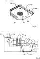
- Fig. 1 shows schematically an oblique view of a device 1 for preparing food.
- the lower part of the device 1 forms the heating device 2 with the heating plate 21 with a control panel 22 and a ventilation grille 23 for the supply of cooling air to the induction coil and control electronics.
- the filter device 3 is arranged on the heating device 2 behind the heating plate 21.
- the inlet opening of the filter device 31 is elongated in the vertical direction. The exhaust air from the cooking process enters through this inlet opening of the filter device 31 until it is filtered and discharged again into the surrounding space through the outlet opening of the filter device 32.
- the covering device 4 is in this case in the closed position and positioned over the upper opening of a pan 7 as a cooking vessel. Via an inlet opening (not visible in the figure) into a flow channel for exhaust air formed within the cover device 4, the exhaust air reaches the inlet opening of the filter device 31 via the outlet opening of the flow channel 52. The position of the outlet opening of the flow channel 52 is not in the closed position The more visible rear first side surface of the cover device 4.
- the cover device 4 can preferably be dismantled by means of a locking device 41, so that the flow channel located therein is accessible for control or cleaning purposes.
- a handle 48 is arranged on the third side surface 45, by means of which the cover device 4 can be moved from an open position into a closed position.
- a multi-armed mechanism in the form of a parallel pivot arm 47 is visible on the fourth side surface 46, which in the closed position applies sufficient force to the cover device 4 to fix the pan 7.
- Fig. 1 it can be clearly seen that the inlet opening of the filter device 31 is elongated in the vertical direction and is generally only partially covered by the outlet opening of the flow channel 52. In this way, comparatively cool outside air can also enter the filter device 3 in order to efficiently cool the exhaust air originating from the cooking process.
- Fig. 2 shows schematically a further oblique view of a device 1 for the preparation of food with a rice cooker 7 as a cooking vessel.
- the rice cooker 7 as an inductive app has a greater height than a pan due to its capacity.
- the cover device 4 is arranged at a greater distance from the heating device 2 in the illustrated closed position. This is easily possible with the parallel pivot arm 47.
- the outlet opening of the flow channel 52 on the first side surface 43 of the cover device 4 is then still immediately in front of the inlet opening of the filter device 31, whereby the exhaust air can flow from the cover device 4 into the filter device 3 for cleaning.
- further means for thermal insulation of the underside of the Inducive app can be present so that the Inducive app can be placed on sensitive surfaces even after its contents have been heated.
- Fig. 3 shows schematically a front view of the heating device 2 and the filter device 3 without the cover device.
- the inlet opening of the filter device 31 is now visible, which is dimensioned in such a way that a height-adjustable cover device with the outlet opening for the exhaust air can be arranged directly in front of it.
- the filter device 3 and the cover device are positioned at a minimum distance from one another, so that the exhaust air cannot flow to the outside in the transition area.
- Fig. 3 The inductive heating plate 21 of the heating device 2 is also visible.
- This cooking area which is generally flat, is also suitable for all different bottom dimensions of the cooking vessels.
- the holding system 9 already ensures secure locking when arranging a cooking vessel before it is put into operation. This is an angle fastened to the filter device 3 which, for example, engages in an upper opening of a pan and causes a form-fitting connection. This fixation is preferably initially carried out independently of the cover device in the function of a lid. In this way, the cookware is already reliably secured even when the cover device is in the open position. The cookware can also be secured in the closed position either alone or in addition by the cover device.
- Fig. 4 shows a rear partial view of the heating device 2 and the filter device 3.
- the rear cover panel of the filter device 3 has been removed.
- the fan 33 is now visible, which is usually arranged in the last section of the exhaust air flow below the outlet opening of the filter device 32.
- the fan 33 is arranged at the end of the exhaust air flow, since this is a component that is relatively difficult to clean.
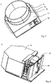
- Fig. 5 shows schematically an oblique view of the cover device 4 as a separate component.
- the inlet opening of the flow channel 51 is arranged centrally on the underside 42. This inlet opening of the flow channel 51 for receiving the vapors produced during the cooking process is in the operating state centrally above the opening of a cooking vessel.
- the outlet opening of the flow channel 52 which, during operation, is arranged directly in front of the inlet opening of the filter device, is indicated by dashed lines on the first side face of the cover device 4, which is remote from it.
- the fourth side surface 46 shows the screw connection point for a multi-armed mechanism.
- Fig. 6 shows a schematic view of the air duct in the filter device 3 and in the cover device 4 of the device according to the invention. Of the heating device located below, only the heating plate 21 is indicated.
- the Fig. 6 shows the operating status.
- a pot 7 is arranged on the heating plate 21.
- the steam generated in the pot 7 is passed through the inlet opening of the flow channel 51.
- the cover device 4 also comprises, as a variant, a flow channel for additional supply air 6, which feeds the supply air from the surroundings into the interior of the pot 7 via a separate inlet opening of the flow channel 61 and an outlet opening of the flow channel 62.
- This air flow mixes with the steam produced in the pot 7 to form the exhaust air flow, which is passed through the flow channel for exhaust air 5.
- the exhaust air can be passed through a first filter 34 which, for example, first filters out the particles.
- the pre-filtered exhaust air then passes into a second filter 35 which, for example as a carbon filter, removes unpleasant odors.
- the cleaned exhaust air is blown out to the environment by the fan 33 via the outlet opening of the filter device 32.
- Fig. 7 shows schematically a view of a cooking vessel 7. It is a rice cooker which, as an inductive app, is equipped with additional control and regulation electronics and an additional inductive component.
- these inductive apps have their own self-sufficient control, which corresponds in handling with the control of the heating plate.
- the control panel of the heating device on the control panel 75 of the cooking vessel is preferably uniformly matched to one another in terms of its technical design as well as its design and is arranged immediately adjacent. Both act like a single control unit for the user during operation.
- the cooking vessel 7 consists of a separate induction cooking point 71, on which the container 73 is arranged by means of a retaining ring 72 and is securely fixed there.
- the handle strip 74 is used for safe handling for introducing and removing the food after the cooking process.
- Such additional devices can also be used more universally and offer effective use of the valuable work area in an aircraft galley.
- the separate induction hotplate 71 as a passive component without its own control elements and heating elements or only with elements for displaying an operating state.
- a view of a toaster device 8 is shown schematically. This is also positioned between the heating device 2 and the covering device 4 during use and is held securely by fixations.
- the toaster device 8 in turn forms a previously described inductive app with a housing 81 and a toaster drawer 82 which can be pulled out in the housing 81 and has a locking device (not specifically designated).
- a handle 83 is mounted on the toaster drawer 82. It is furthermore conceivable to provide an additional transport lock in the form of a hook or bolt which is arranged laterally on the toaster device 8 and is not shown separately in the figure.
- Figure 9 shows an advantageous operating concept, in particular for operating the cooking vessel 7 for preparing rice dishes.
- the control panel 22 ' is designed as a so-called slider, which is on the part of an operator can be operated by swiping your finger and then lifting your finger in the desired position or by tapping it directly.
- the slider corresponds to a display field 75 'which is arranged on the rice cooker 7, which is not shown separately in FIG.
Landscapes
- Engineering & Computer Science (AREA)
- Chemical & Material Sciences (AREA)
- Chemical Kinetics & Catalysis (AREA)
- Food Science & Technology (AREA)
- Electromagnetism (AREA)
- Physics & Mathematics (AREA)
- Combustion & Propulsion (AREA)
- General Engineering & Computer Science (AREA)
- Mechanical Engineering (AREA)
- Health & Medical Sciences (AREA)
- Environmental & Geological Engineering (AREA)
- Toxicology (AREA)
- Electric Stoves And Ranges (AREA)
- Commercial Cooking Devices (AREA)
- Cookers (AREA)
Description
- Die Erfindung betrifft eine Vorrichtung zur Zubereitung von Speisen nach dem Oberbegriff des Anspruchs 1.
- In Flugzeugen werden Speisen üblicherweise mit besonderen Flugzeugkocheinrichtungen zubereitet. Flugzeuge im Linienbetrieb weisen dazu beispielsweise Heißluftöfen zur Erwärmung abgepackter Speisen auf. In individuell ausgestatteten Flugzeugen wird auch Kochgeschirr in Form von Töpfen, Pfannen und Woks eingesetzt. Diese werden dabei häufig mitsamt Deckel über Sicherheitsbügel auf der Kochstelle fixiert, wobei gleichzeitig mehrere Töpfe durch einen Schutzbügel festgehalten werden. Eine Fixierung des Kochgeschirrs ist wichtig, damit bei Flugturbulenzen keine heißen Speisen unkontrolliert in die Kabine gelangen. Diese Sicherheitsaspekte stellen besondere Anforderungen an die Gestaltung und die Handhabung von Flugzeugkocheinrichtungen.
- So ist aus der Druckschrift
EP BE- 1 596 694 B1 - Des Weiteren ist aus der Druckschrift
DE 10 2012 213 811 A1 eine Flugzeugkocheinrichtung mit einem Kochgeschirr und einem mit dem Kochgeschirr fest verbindbaren Deckel bekannt. Die Flugzeugkocheinrichtung ist auf einer Kochstelle fixierbar, wobei der Deckel mindestens ein bewegliches Element aufweist, durch dessen Bewegung eine Öffnung oder mehrere Öffnungen zum Innenraum des Kochgeschirrs freilegbar sind. Die Kochstelle kann auch mit Abzugshauben ausgestattet sein. Durch das Freilegen der Öffnung wird ein Zugang zum Innenraum des Kochgeschirrs ermöglicht. Es müssen dafür keine Schutzbügel oder Deckel abgebaut oder auf sonstige Weise entfernt werden. Eine Bewegung des beweglichen Elements reicht aus, um temporären Zugang zum Kochgut zu erlangen. Die Öffnung erlaubt dabei den Zugriff auf das Kochgut. Die Zugangsöffnung ist so groß, dass beispielsweise Zutaten zugegeben werden können oder ein Kochlöffel eingebracht werden kann. Das bewegliche Element kann verschiedenartig ausgestaltet sein, indem es radial oder tangential verschiebbar ist. Es kann beispielsweise auf einem Abschnitt einer Kreisbahn oder eines Spiralbogens verschoben werden. Eine tangentiale Bewegungsrichtung ist insbesondere bei runden Töpfen vorteilhaft, da diese Bewegungsrichtung in Umfangsrichtung gleichförmig zur Form des Topfes verläuft. - Eine weitere Vorrichtung zur Zubereitung von Speisen ist aus der Europäischen Patentanmeldung
EP 1 296 096 A2 bekannt. In der genannten Schrift ist eine mobile Dunstabzugsvorrichtung offenbart, bei welcher eine Absaughaube über ein eine horizontale Drehachse aufweisendes Drehgelenk mit einem Ständer verbunden ist. - Aufgabe der vorliegenden Erfindung ist es, eine Vorrichtung zur Zubereitung von Speisen weiterzubilden.
- Diese Aufgabe wird gelöst durch die Vorrichtung mit den Merkmalen des Anspruchs 1. Die Unteransprüche betreffen vorteilhafte Ausführungsformen und Varianten der Erfindung.
- Die Erfindung schließt eine Vorrichtung zur Zubereitung von Speisen ein, umfassend eine Heizeinrichtung mit Heizplatte, eine Filtereinrichtung und eine mit der Filtereinrichtung in Wirkverbindung stehende Abdeckeinrichtung mit einer Oberseite, einer Unterseite und Seitenflächen. Die Abdeckeinrichtung weist an der Unterseite zumindest eine Eintrittsöffnung eines im Inneren der Abdeckeinrichtung angeordneten Strömungskanals für Abluft auf. Der Strömungskanal weist an einer ersten Seitenfläche eine Austrittsöffnung auf, wobei die Austrittsöffnung derart positionierbar ist, dass die Abluft über die Austrittsöffnung in eine Eintrittsöffnung der Filtereinrichtung strömen kann.
- Erfindungsgemäß ist die Abdeckeinrichtung durch eine mehrarmige Mechanik in Form eines Parallelschwenkarms parallel verschiebbar.
- Somit ist die Abdeckeinrichtung zumindest im Raum parallel verschiebbar angeordnet. Zur Parallelführung können entsprechende Lagerstellen, wie beispielsweise mittels Kugellagern aufeinander abgleitenden Schienen, eine kraftsparende bedienerfreundliche Unterstützung bieten. Die Abdeckeinrichtung kann als bewegliches Element direkt, beispielsweise über einen am beweglichen Element angebrachten Handgriff, bewegt und auf dem Kochgefäß positioniert werden.
- Die Erfindung umfasst unter dem Begriff Zubereitung von Speisen auch die Zubereitung von Getränken oder die Erwärmung von Wasser. In diesem Zusammenhang und bei allen weiteren Ausgestaltungen der Erfindung soll der Begriff Speisen jegliche Art von Nahrungsmitteln umfassen.
- Die Erfindung betrifft eine Kochstelle bevorzugt für Flugzeuge oder auch andere Transportmittel, die als relativ kleines Gerät auch auf engem Raum verbaut oder eingeschoben werden kann. Hierbei kann ein derartiges modulares und mobiles System platzsparend in ein Regal eingebaut und an das Bordnetz eines Flugzeuges angeschlossen werden. Die Kochstelle kann in einem Flugzeug als Einschub oder als Auf-Tisch-Version bei Bedarf unmittelbar in Betrieb genommen werden. Zur Zubereitung von Speisen ist eine Heizeinrichtung in Form einer flachen Heizplatte vorgesehen. Aus praktischen Gründen ist die Heizplatte der Kochstelle unmittelbar von einer Bedienperson bevorzugt von vorne her zugänglich und die Filtereinrichtung dahinter als Filterkasten angeordnet. Die Abdeckeinrichtung kann dabei beweglich am Filterkasten gehaltert sein.
- Die erfindungsgemäße Vorrichtung weist eine Filtereinrichtung und eine mit der Filtereinrichtung in Wirkverbindung stehende Abdeckeinrichtung als integrierte Dunstabzugshaube auf. Die Wirkverbindung besteht darin, dass die bei der Speisenzubereitung entstehenden Dämpfe in einem Strömungskanal innerhalb der Abdeckeinrichtung hindurchgeführt werden und durch eine beispielsweise an einer Stirnseite befindliche Austrittsöffnung austreten und von dort aus unmittelbar in die Filtereinrichtung einströmen. Diese Austrittsöffnung an der Stirnseite ist folglich unmittelbar zur Eintrittsöffnung der Filtereinrichtung benachbart. Diese erste Seitenfläche an der Stirnseite kann zur Führung und Formung des Abluftstroms auch zusätzliche geeignete Mittel aufweisen.
- Für jede Form und Größe eines Kochgefäßes ist die Abdeckeinrichtung so konzipiert, dass diese zur Zubereitung von Speisen das Kochgefäß gleich einem Deckel abdeckt. Die an der Unterseite der Abdeckeinrichtung vorhandene Eintrittsöffnung für die Abluft wird folglich auf dem nach oben offenen Koch- oder Bratgefäß positioniert.
- Insbesondere die unterschiedliche Höhe der Kochgefäße macht es erforderlich, die Abdeckeinrichtung flexibel zu positionieren. Hierbei kann das Kochgefäß entweder komplett verschlossen werden oder ein definierter Spalt verbleiben, durch den Luft aus der Umgebung hindurch treten kann.
- Dabei ermöglicht ein variabel einstellbarer Abstand der Abdeckeinrichtung zur Heizplatte, dass die an der Stirnseite befindliche Austrittsöffnung an einer langgestreckten Eintrittsöffnung der Filtereinrichtung entlang geführt werden kann.
- Dringt von außen Frischluft hinzu, wird hierdurch die Abluft im Strömungskanal der Abdeckeinrichtung bereits so weit abgekühlt, dass sich beispielsweise das im Luftstrom mitgeführte Fett an der Wandung niederschlägt. Dieser gewünschte Effekt bewirkt, dass bereits von der Wandung des Strömungskanals ein Filtereffekt ausgeht. Durch das Hinzuführen von Frischluft wird auch einer Überhitzung vorgebeugt. Dennoch können an geeigneten Stellen Temperatursensoren oder Temperatursensorschaltelemente vorhanden sein, die bei Erreichen von vorgebbaren Maximaltemperaturen eine Abschaltung der Vorrichtung auslösen.
- Ebenso kann im Abluftkanal ein Sensor zur Raucherkennung angeordnet sein. Dieser sicherheitstechnische Aspekt soll insbesondere beim Zubereiten von gebratenen Speisen eine Flammbildung im Gefäßinneren frühzeitig erkennen.
- Der besondere Vorteil der Erfindung besteht darin, dass ein kompaktes, leichtes Gerät, insbesondere in Flugzeugen, ein sicheres und komfortables Zubereiten von Speisen ermöglicht. Unerwünschte oder unangenehme Gerüche werden durch die Filtereinrichtung herausgefiltert. Hierbei übt die Abdeckvorrichtung eine Mehrfachfunktion aus. Zudem dient sie als Spritzschutz, Dunstabzug und zur Sicherung der Kochgefäße. Eine einfache Fixierung des Kochgefäßes auf der Heizplatte ermöglicht auch eine Einhand-Bedienung bei der Zubereitung. Durch eine effiziente Filterung der Abluft kommt es zu keiner Geruchsbelästigung der Passagiere.
- In vorteilhafter Ausgestaltung der Erfindung kann der Strömungskanal zwischen Eintrittsöffnung und Austrittsöffnung zumindest abschnittsweise eine mehrfache Umlenkung des Abluftstroms bewirken. Mehrfache Umlenkungen verlängern den Weg der Abluft und können in Verbindung mit einer beabsichtigten Wirbelbildung die Abluft bereits in der Abdeckeinrichtung ausreichend weit abkühlen, damit Fett abgeschieden wird. Insgesamt wird durch derartige Maßnahmen die Abluft so weit abgekühlt, das diese nach dem Durchtritt durch die Filtereinrichtung in die Umgebung ausgeblasen werden kann. Die Abdeckeinrichtung kann natürlich zum Reinigen des Strömungskanals mit wenigen Handgriffen zerlegt und wieder zusammengebaut werden.
- Vorteilhafterweise kann der Strömungskanal zwischen Eintrittsöffnung und Austrittsöffnung zumindest abschnittsweise mäanderförmig ausgebildet sein. Hierdurch wird zur Abkühlung der Abluft und zur Fettabscheidung bereits in der Abdeckeinrichtung ein ausreichend langer Weg bis zur eigentlichen Filtereinrichtung geschaffen.
- In einer alternativen Ausgestaltung kann der Strömungskanal zwischen Eintrittsöffnung und Austrittsöffnung Rippen, zapfenartige Auskragungen oder Gitter zur Umlenkung der Abluft aufweisen. Damit wird einerseits für die Abluft der Weg verlängert und andererseits effizient Wirbelzonen gebildet, an denen ein intensiver Wärmeaustausch mit der Kanalwand stattfindet, um eine frühzeitige Fettabscheidung zu bewirken.
- In vorteilhafter Ausgestaltung der Erfindung kann im Strömungskanal ein Filter angeordnet sein. Zusätzliche Filter unterstützen den Effekt der Fettabscheidung im Strömungskanal. Hier können auch bereits Partikelfilter zum Einsatz kommen, um den Abluftstrom vorzureinigen.
- Vorteilhafterweise kann der Filter aus Metallwolle oder aus offenporigem Metallschaum bestehen. Derartige Filtermaterialien können auch als Flammschutz dienen und durch ihre Kompaktheit in der Filterwirkung besonders effizient sein. Auch die Reinigung derartiger wieder verwendbarer Komponenten ist beispielsweise in Spülmaschinen möglich.
- Daneben ist es auch denkbar, einen zusätzlichen Papierfilter mittels einer Halteeinrichtung vor der Eintrittsöffnung anzuordnen. Ein derartiger Papierfilter - welcher vorzugweise als Einmalfilter ausgebildet sein kann - trägt dazu bei, die Standzeiten der nachfolgenden Filtereinheiten zu erhöhen.
- In weiterer Ausführungsform kann die Abdeckeinrichtung mit einer Flammensperre ausgestattet sein. Derartige Sperren können entweder durch iegelungsmechanismen wirken, die den entzündeten Abluftstrom blockieren oder aus porösen Keramikmaterialien oder aus offenporigem Metallschaum bestehen. Geeignete Temperatur- und/oder Feuersensoren können dabei das Überschreiten kritischer Temperaturen detektieren und eine Gefahrensituation anzeigen bzw. steuernd eingreifen.
- Des Weiteren kann die Abdeckeinrichtung bevorzugt zwischen einer Offenstellung und einer Schließstellung verschiebbar sein. In der Offenstellung können die Gefäße zur Zubereitung der Speisen problemlos eingebracht oder wieder entfernt werden. In der Schließstellung kann die Abdeckeinrichtung als bewegliches Element verriegelbar ausgeführt sein. Die Verriegelung verhindert, dass die Abdeckeinrichtung ein Kochgefäß unerwünscht freigibt. Aus sicherheitstechnischen Gründen ist dies besonders im Luftverkehr unabdingbar. Auch kann beispielsweise bei bestimmten Flugmanövern oder Turbulenzen gewünscht sein, dass in der Schließstellung ein automatischer Verriegelungsmechanismus wirkt, der in Gefahrensituationen nicht gelöst werden kann. Hierbei helfen Beschleunigungs- oder Neigungssensoren, die Gefahrensituation anhand von Schwellwerten zu erkennen. Zwischen Offenstellung und der vorgesehenen Schließstellung kann die Abdeckeinrichtung jedoch auch so ausgeführt sein, dass diese in jeder Zwischenstellung fixierbar oder arretierbar ist.
- In vorteilhafter Ausgestaltung der Erfindung kann die Abdeckeinrichtung zumindest in Schließstellung mit Federkraft beaufschlagt sein. Hierdurch wird ein automatischer Verschlussmechanismus erzeugt, der die Haltekraft auf das darunter angeordnete Kochgefäß ausgeübt. Hierbei kann ein mechanisches Federsystem eine Art Sicherungseinrichtung darstellen, welche in einer Gefahrensituation automatisch reagiert, sobald die Flugzeugbeschleunigung einen zulässigen Schwellwert überschritten hat. Hierzu umfasst die Flugzeugkocheinrichtung bevorzugt einen Beschleunigungssensor und Neigungssensor.
- Erfindungsgemäß ist die Abdeckeinrichtung durch eine mehrarmige Mechanik in Form eines Parallelschwenkarms parallel verschiebbar. Durch eine Parallelverschiebung kann die Öffnung eines Kochgefäßes unmittelbar flächig abgedeckt und das Gefäß stabilisiert werden.
- Vorteilhafterweise kann die mehrarmige Mechanik seitlich an der Filtereinrichtung sowie seitlich an zumindest einer der Seitenflächen der Abdeckeinrichtung ansetzen. Damit kann die Abdeckeinrichtung parallel über die Filtereinrichtung geschwenkt werden, um so die Öffnung eines Kochgefäßes freizugeben.
- In besonders bevorzugter Ausgestaltung kann die Abdeckeinrichtung zusätzlich um zumindest eine Achse schwenkbar sein. Hierdurch kann das Freigeben der oberen Öffnung eines Kochgefäßes noch einfacher gestaltet werden, um das Kochgut zugänglich zu machen. Durch ein Schwenken kann auch die Unterseite mit der Eintrittsöffnung für die Abluft in einfacher Weise zugänglich werden. Gegebenenfalls kann dies für eine Reinigung der Unterseite zweckmäßig sein.
- Vorteilhafterweise kann die Filtereinrichtung einen Ventilator zur Erzeugung eines Abluftstroms aufweisen. Bevorzugt ist der Ventilator auch regelbar, um die Intensität des Abluftstroms nach Bedarf steuern zu können.
- In weiterer vorteilhafter Ausgestaltung der Erfindung kann die Filtereinrichtung mehrere in Strömungsrichtung hintereinander angeordnete Filter aufweisen. Hierdurch können Filter mit unterschiedlicher Funktion kombiniert werden. Beispielsweise können nach einer Fettabscheidung in einer im Abluftstrom nachgeordneten Position ein Partikelfilter und anschließend ein Kohlenstofffilter zur vollständigen Entfernung störender Gerüche aufeinanderfolgen. Derartige dreistufige oder auch mit einer Fettabscheidung vierstufige Filter sind besonders effizient.
- In weiterer ergänzender Ausführungsform kann jeder Filter einzeln austauschbar sein. In der Filtereinrichtung sind die Filter mittels Halterungen so fixiert, dass diese auf einfache Weise herausgenommen oder eingeschoben werden können. Neben Einmalfiltern können auch reinigbare Filter zum Einsatz kommen.
- Daneben kann auch eine integrierte Ausbildung eine Filterkassette, welche als bauliche Einheit sämtliche der Filtereinrichtung zugehörige Filter umfasst, vorhanden sein. In diesem Fall lässt sich in vorteilhafter Weise die gesamte Kassette auf einmal aus der Anordnung entnehmen. Hierdurch vereinfacht sich aufgrund der dann besseren Zugänglichkeit der einzelnen Filter die Wartung der Filtereinheit oder ein Austausch einzelner Filter erheblich.
- Vorteilhafterweise kann die Heizplatte eine induktive Heizung aufweisen. Die Steuerung der induktiven Heizung kann mittels Nahfeldkommunikation NFC oder durch andere geeignete Steuerungseinrichtungen erfolgen. Der Energiebedarf für die Steuerung durch NFC liegt lediglich im Bereich von wenigen Watt. Die Elektronik und Regeltechnik ist darauf ausgelegt, dass wenig Leistung benötigt wird. Über Benutzer- und Kontrollanzeigen kann der Benutzer die Generatorleistung für die induktiven Spulen mit einer Zeitvorwahl an einem Bedienpanel auswählen. Moderne Bedienpanels erlauben eine Einstellung mittels direkter Anwahl oder durch sogenannte Slider mittels einer mit einem Finger ausgeführten Wisch- oder Ziehbewegung.
- Bevorzugt kann zwischen der Heizplatte und der Abdeckeinrichtung ein Kochgefäß anordenbar sein. Die gesamte Anordnung und Dimensionierung der Vorrichtung soll den Einsatz unterschiedlicher Kochgefäße ermöglichen. Flache sowie im Volumen große und hohe Gefäße passen zwischen die flexibel anordenbare Abdeckeinrichtung und die Heizplatte.
- In vorteilhafter Ausgestaltung der Erfindung kann das Kochgefäß eine Pfanne, ein Topf, ein Wok, ein Dampfgarer oder eine Vorrichtung zur Zubereitung von Reis sein.
- Kochgefäße und insbesondere Pfannen können aus Materialien bestehen, die einen Überhitzungsschutz aufweisen. Diese Materialien haben einen Curie-Punkt beispielsweise zwischen 200°C und 250°C, oberhalb dessen das Material nicht mehr magnetisch ist und so einer Überhitzung vorbeugt. So kann durch die physikalischen Eigenschaften des Materials selbst, zusätzlich zur Steuerung und Regelung des Kochfeldes, die Sicherheit des Systems erhöht werden.
- Weitere auf den Bedarf angepasste Kochgefäße sind die sogenannten Inductive-Apps. Es handelt sich um Kocheinrichtungen, die zur induktiven Kochstelle selbst über eine zusätzliche Steuerungs- und Regelungselektronik und zusätzliche induktive Komponenten und Temperatursensoren verfügen. Inductive-Apps werden induktiv und drahtlos mit Strom versorgt, auch die Datenübertragung erfolgt drahtlos. Hierzu haben Inductive-Apps ihre eigene autarke Steuerung, um eine intuitive Benutzung bei optimalem Kochergebnis und Servicequalität zu erzielen. Beispiele für Inductive-Apps sind Toaster, Reiskocher, Wok und Dampfgarer. Aber auch andere Küchengeräte wie Kaffeemaschine und Wasserkocher können auf dieser Basis funktionieren. Derartige Zusatzgeräte bedingen eine multiple und effektive Nutzung des begrenzten Arbeitsbereichs in einer Flugzeugbordküche und ermöglichen flexible Catering-Abläufe. Beispielsweise hat ein Reiskocher ein Fassungsvermögen von ca. 2,5 l und bereitet automatisch in einem Kochgefäß Reis, Suppe und weitere Speisen zu. So wird auch das Braten von Fleisch, Fisch, Eiern und Gemüse in Gastronomiequalität möglich.
- Vorteilhafterweise kann zwischen der Heizplatte und der Abdeckeinrichtung eine Toastereinrichtung anordenbar sein. Die Toastereinrichtung ist ein weiteres Beispiel für eine Inductive-App, welche indirekt mit einer Sekundärspule beheizt wird. Über einen NFC-Steuerkreislauf beheizt die Sekundärspule die eigentlichen Heizelemente. Mittels einer intelligenten Zeitsteuerung können mehrere Toasts in den gewünschten Bräunungsstufen zubereitet werden. Auch eine Toastereinrichtung ist an das Abluftsystem der Filtereinrichtung angedockt, wodurch die Möglichkeit besteht, das Geräteinnere und die Außenwände aktiv zu kühlen. Durch die beschriebenen Inductive-Apps wird eine Minimierung des benötigten Strombedarfs und des Gesamtgewichts der Bordküche mit hoher Energieeffizienz und einer multiplen Nutzung der Kochgeräte möglich. Inductive-Apps können an geeigneten Orten während sie nicht benutzt werden verstaut werden.
- Für die Identifikation des jeweiligen Einschubelementes können Elektromagnete oder Induktionsspulen zur Detektion lediglich kurzzeitig eingeschaltet werden und die Identifikation durch Erkennung des entweder vorhandenen oder nicht vorhandenen elektromagnetisch detektierbaren Elementes erfolgen.
- Vorteilhafterweise kann das Kochgefäß oder die Toastereinrichtung an der Heizeinrichtung und/oder der Filtereinrichtung und/oder an der Abdeckeinrichtung durch ein Haltesystem arretierbar und wieder lösbar sein. Vorzugsweise ist das Kochgeschirr durch eine formschlüssige Verbindung auf der Heizplatte fixierbar. Die formschlüssige Verbindung ist vorzugsweise durch ein Gewinde, einen Niederhalter oder einen Schnellverschluss realisiert. Die formschlüssige Verbindung kann auch einen Bajonettverschluss oder Pins umfassen. Diese Fixierung erfolgt bevorzugt zunächst unabhängig von der Abdeckeinrichtung in Funktion eines Deckels. So wird das Kochgeschirr auch bei einer in Öffnungsstellung befindlichen Abdeckeinrichtung bereits zuverlässig gesichert. Eine Sicherung des Kochgeschirrs kann aber auch alleine oder zusätzlich durch die Abdeckeinrichtung in Schließstellung erfolgen.
- Die Inductive-Apps können als Einschubelemente vor der eigentlichen Erwärmung vorbestückt und bei Bedarf dem Induktionsofen zugeführt werden, wobei dann die Erwärmung der Speisen innerhalb sehr kurzer Zeit, d. h. innerhalb weniger Minuten erreicht werden kann.
- In vorteilhafter Ausgestaltung der Erfindung kann die Abdeckeinrichtung in der Schließstellung das Kochgefäß bzw. die Toastereinrichtung arretieren. Hierbei kann an der Filtereinrichtung oder an der Heizeinrichtung eine zusätzliche seitliche bevorzugt über eine Achse schwenkbare Arretierung vorteilhaft sein.
- Vorteilhafterweise kann in der Abdeckeinrichtung ein weiterer Strömungskanal für Zuluft mit einer Eintrittsöffnung an der Unterseite der Abdeckeinrichtung ausgeführt sein, so dass Außenluft zugeführt werden kann. Hierdurch wird zusätzliche Frischluft in den Abluftstrom eingebracht, wodurch dieser abgekühlt wird. Dies ist ein wichtiger sicherheitstechnischer Gesichtspunkt, im Abluftstrom möglichst schnell eine ausreichend geringe Temperatur zu erlangen.
- Vorteilhafterweise kann in Schließstellung zumindest eine Durchtrittsöffnung zwischen Kochgefäß und der Unterseite der Abdeckeinrichtung ausgebildet sein. Durchtrittsöffnungen dienen ebenfalls zur Frischluftzufuhr in den Abluftstrom. Hierbei kann es sich um zusätzliche meist ringförmige Aufsätze mit Ausnehmungen handeln, die beim Kochvorgang zwischen dem oberen Rand des Kochgefäßes und der Unterseite der Abdeckeinrichtung positioniert sind. Hierdurch wird über die Größe der Ausnehmungen der Frischluftstrom geregelt. Die Regelung des Zustroms an Frischluft kann auch über in der Größe variable Ausnehmungen erfolgen.
- In vorteilhafter Ausgestaltung der Erfindung kann in Schließstellung die zumindest eine Durchtrittsöffnung spaltförmig oder kreisförmig ausgebildet sein. Hierdurch werden fensterartige Öffnungen ausgebildet, deren Öffnungsflächen zur Regelung des Luftstroms gegebenenfalls vergrößert oder verkleinert werden können. Hierzu können gegeneinander verschiebbare Doppelringe mit sich gegenseitig abdeckenden Durchtrittsöffnungen dienen.
- Nachfolgend wird die Erfindung anhand der Zeichnungen exemplarisch erläutert. Es zeigen:
- Figur 1
- Schematisch eine Schrägansicht einer Vorrichtung zur Zubereitung von Speisen;
- Figur 2
- Schematisch eine weitere Schrägansicht einer Vorrichtung zur Zubereitung von Speisen mit einem zusätzlichen Kochgefäß;
- Figur 3
- Schematisch eine vorderseitige Ansicht der Heizeinrichtung und der Filtereinrichtung;
- Figur 4
- Schematisch eine rückseitige Ansicht der Heizeinrichtung und der Filtereinrichtung;
- Figur 5
- Schematisch eine Schrägansicht der Abdeckeinrichtung;
- Figur 6
- Schematisch eine Ansicht der Luftführung in der Filtereinrichtung und in der Abdeckeinrichtung;
- Figur 7
- Schematisch eine Ansicht eines Kochgefäßes;
- Figur 8
- Schematisch eine Ansicht einer Toastereinrichtung;
- Figur 9
- Schematisch eine Bedieneinrichtung.
-
Fig. 1 zeigt schematisch eine Schrägansicht einer Vorrichtung 1 zur Zubereitung von Speisen. Der untere Teil der Vorrichtung 1 bildet die Heizeinrichtung 2 mit der Heizplatte 21 mit einem Bedienfeld 22 und einem Lüftungsgitter 23 für die Zufuhr von Kühlluft zur Induktionsspule und Steuerungs-/Regelungs-Elektronik. - Die Filtereinrichtung 3 ist auf der Heizeinrichtung 2 hinter der Heizplatte 21 angeordnet. Die Eintrittsöffnung der Filtereinrichtung 31 ist in senkrechter Richtung langgestreckt ausgebildet. Durch diese Eintrittsöffnung der Filtereinrichtung 31 tritt die Abluft des Kochvorganges ein, bis diese gefiltert und geruchsneutral durch die Austrittsöffnung der Filtereinrichtung 32 wieder in den umgebenden Raum abgegeben wird.
- Die Abdeckeinrichtung 4 ist in diesem Falle in Schließstellung und über der oberen Öffnung einer Pfanne 7 als Kochgefäß positioniert. Über eine in der Figur nicht sichtbare Eintrittsöffnung in einen innerhalb der Abdeckeinrichtung 4 ausgebildeten Strömungskanal für Abluft gelangt die Abluft über die Austrittsöffnung des Strömungskanals 52 in die Eintrittsöffnung der Filtereinrichtung 31. Die Position der Austrittsöffnung des Strömungskanals 52 befindet sich an einer in der Schließstellung nicht mehr sichtbaren rückwärtigen ersten Seitenfläche der Abdeckeinrichtung 4. Mittels einer Verriegelungseinrichtung 41 ist die Abdeckeinrichtung 4 bevorzugt zerlegbar, so dass der darin befindliche Strömungskanal für Kontroll- oder Reinigungszwecke zugänglich ist. An der dritten Seitenfläche 45 ist ein Griff 48 angeordnet, mittels dem die Abdeckeinrichtung 4 von einer Offenstellung in eine Schließstellung verschoben werden kann. An der vierten Seitenfläche 46 ist eine mehrarmige Mechanik in Form eines Parallelschwenkarms 47 sichtbar, welche die Abdeckeinrichtung 4 in der Schließstellung zur Fixierung der Pfanne 7 ausreichend mit Kraft beaufschlagt.
- In
Fig. 1 ist gut erkennbar, dass die Eintrittsöffnung der Filtereinrichtung 31 in senkrechter Richtung langgestreckt ausgebildet ist und dabei von der Austrittsöffnung des Strömungskanals 52 im Regelfall nur teilweise abgedeckt wird. Auf diese Weise kann auch vergleichsweise kühle Außenluft in die Filtereinrichtung 3 eintreten, um die aus dem Kochvorgang stammende Abluft effizient abzukühlen. -
Fig. 2 zeigt schematisch eine weitere Schrägansicht einer Vorrichtung 1 für die Zubereitung von Speisen mit einem Reiskocher 7 als Kochgefäß. In dieser Figur ist erkennbar, dass der Reiskocher 7 als Inductive-App durch sein Fassungsvolumen eine größere Höhe als eine Pfanne aufweist. Hierdurch wird die Abdeckeinrichtung 4 in der dargestellten Schließstellung in einem größeren Abstand zur Heizeinrichtung 2 angeordnet. Durch den Parallelschwenkarm 47 ist dies problemlos möglich. Die Austrittsöffnung des Strömungskanals 52 an der ersten Seitenfläche 43 der Abdeckeinrichtung 4 befindet sich dann immer noch unmittelbar vor der Eintrittsöffnung der Filtereinrichtung 31, wodurch die Abluft aus der Abdeckeinrichtung 4 zur Reinigung in die Filtereinrichtung 3 strömen kann. Insbesondere in einer Ausführung des Reiskochers 7 mit einem induktionsfähigen Topf können weitere Mittel zur thermischen Isolierung der Unterseite der Inducive-App vorhanden sein, so dass die Inductive App auch nach der Erwärmung ihres Inhaltes auf empfindlichen Flächen abgestellt werden kann. -
Fig. 3 zeigt schematisch eine vorderseitige Ansicht der Heizeinrichtung 2 und der Filtereinrichtung 3 ohne die Abdeckeinrichtung. Sichtbar ist nun die Eintrittsöffnung der Filtereinrichtung 31, die so dimensioniert ist, dass eine in der Höhe verstellbare Abdeckeinrichtung mit der Austrittsöffnung für die Abluft unmittelbar davor angeordnet werden kann. Im Betrieb sind die Filtereinrichtung 3 und die Abdeckeinrichtung in einem Minimalabstand zueinander positioniert, so dass im Übergangsbereich die Abluft nicht nach außen strömen kann. - In
Fig. 3 ebenfalls sichtbar ist die induktive Heizplatte 21 der Heizeinrichtung 2. Diese im Regelfall ebene Kochstelle ist auch für alle unterschiedlichen Bodenabmessungen der Kochgefäße geeignet. - Das Haltesystem 9 sorgt bereits für eine sichere Arretierung bei der Anordnung eines Kochgefäßes vor der Inbetriebnahme. Hier handelt es sich um einen an der Filtereinrichtung 3 befestigten Winkel, der beispielsweise in eine obere Öffnung einer Pfanne eingreift und eine formschlüssige Verbindung bedingt. Diese Fixierung erfolgt bevorzugt zunächst unabhängig von der Abdeckeinrichtung in Funktion eines Deckels. So wird das Kochgeschirr auch bei einer in Öffnungsstellung befindlichen Abdeckeinrichtung bereits zuverlässig gesichert. Eine Sicherung des Kochgeschirrs kann aber auch alleine oder zusätzlich durch die Abdeckeinrichtung in Schließstellung erfolgen.
-
Fig. 4 zeigt eine rückseitige Teilansicht der Heizeinrichtung 2 und der Filtereinrichtung 3. Die rückseitige Abdeckblende der Filtereinrichtung 3 ist entfernt. Innerhalb der Filtereinrichtung 3 ist nun der Ventilator 33 sichtbar, der in der Regel im letzten Abschnitt des Abluftstroms unterhalb der Austrittsöffnung der Filtereinrichtung 32 angeordnet ist. Der Ventilator 33 ist am Ende des Abluftstroms angeordnet, da dieser ein relativ schlecht zu reinigendes Bauteil darstellt. -
Fig. 5 zeigt schematisch eine Schrägansicht der Abdeckeinrichtung 4 als separates Bauteil. An der Unterseite 42 ist die Eintrittsöffnung des Strömungskanals 51 mittig angeordnet. Diese Eintrittsöffnung des Strömungskanals 51 zur Aufnahme der beim Kochvorgang entstehenden Dämpfe liegt im Betriebszustand zentral über der Öffnung eines Kochgefäßes. An der abgewandten ersten Seitenfläche der Abdeckeinrichtung 4 ist gestrichelt die Austrittsöffnung des Strömungskanals 52 angedeutet, die im Betrieb unmittelbar vor der Eintrittsöffnung der Filtereinrichtung angeordnet ist. An der dritten Seitenfläche 45 ist ein mit einer Hand komfortabel bedienbarer Griff 48 dezentral montiert. Die vierte Seitenfläche 46 zeigt die Verschraubungsstelle für eine mehrarmige Mechanik. -
Fig. 6 zeigt schematisch eine Ansicht der Luftführung in der Filtereinrichtung 3 und in der Abdeckeinrichtung 4 der erfindungsgemäßen Vorrichtung. Von der darunter befindlichen Heizeinrichtung ist nur die Heizplatte 21 angedeutet. - Die
Fig. 6 zeigt den Betriebszustand. Hierzu ist auf der Heizplatte 21 ein Topf 7 angeordnet. Der im Topf 7 entstehende Dampf wird über die Eintrittsöffnung des Strömungskanals 51 geleitet. Dies ist mit Pfeilen dargestellt, welche die Strömung der Abluft darstellen. Die Abdeckeinrichtung 4 umfasst in diesem Fall als Variante auch einen Strömungskanal für zusätzliche Zuluft 6, der über eine separate Eintrittsöffnung des Strömungskanals 61 und eine Austrittsöffnung des Strömungskanals 62 die Zuluft aus der Umgebung in das Innere des Topfes 7 zuführt. Dieser Luftstrom vermischt sich mit dem im Topf 7 entstehenden Dampf zum Abluftstrom, der durch den Strömungskanal für Abluft 5 geleitet wird. Auf dem Weg von der Eintrittsöffnung des Strömungskanals 51 zur Austrittsöffnung des Strömungskanals 52 befinden sich Rippen 53 die den Abluftstrom mehrfach umlenken und dabei eine Wirbelbildung verursachen. Die mehrfachen Umlenkungen verlängern den Weg der Abluft. Durch eine Wirbelbildung findet ein intensiver Wärmeaustausch mit der Kanalwand statt, wodurch die Abluft bereits in der Abdeckeinrichtung 4 ausreichend weit zur Fettabscheidung abgekühlt wird. Die Abdeckeinrichtung 4 kann zur Reinigung mit wenigen Handgriffen zerlegt und wieder zusammengebaut werden. - Über die unmittelbar vor der Eintrittsöffnung der Filtereinrichtung 31 angeordnete Austrittsöffnung des Strömungskanals 52 kann die Abluft durch einen ersten Filter 34, der beispielsweise zunächst die Partikel herausfiltert, geleitet werden. Danach gelangt die vorgefilterte Abluft in einen zweiten Filter 35, der beispielsweise als Karbonfilter störende Gerüche entfernt. Im weiteren Verlauf wird die gereinigte Abluft durch den Ventilator 33 über die Austrittsöffnung der Filtereinrichtung 32 an die Umgebung ausgeblasen.
-
Fig. 7 zeigt schematisch eine Ansicht eines Kochgefäßes 7. Es handelt sich um einen Reiskocher, der als Inductive-App mit einer zusätzliche Steuerungs- und Regelungselektronik und einer zusätzlichen induktive Komponente ausgestattet ist. Hierzu haben diese Inductive-Apps eine eigene autarke Steuerung, die in der Handhabung mit der Steuerung der Heizplatte korrespondiert. Hierzu wird bevorzugt auch das Bedienfeld der Heizeinrichtung auf das Bedienfeld 75 des Kochgefäßes in der technischen Ausführung wie auch im Design einheitlich aufeinander abgestimmt und unmittelbar benachbart angeordnet. So wirken beide im Betrieb auf den Benutzer wie eine einheitliche Steuereinheit. - Bei der in
Fig. 7 dargestellten Ausführungsform besteht das Kochgefäß 7 aus einer separaten Induktionskochstelle 71, auf der mittels eines Halterings 72 das Behältnis 73 angeordnet und dort sicher fixiert ist. Die Griffleiste 74 dient zum sicheren Handling zum Einbringen und zur Entnahme der Speisen nach dem Kochvorgang. Derartige Zusatzgeräte sind auch universeller einsetzbar und bieten eine effektive Nutzung des wertvollen Arbeitsbereichs in einer Flugzeugbordküche. - Es ist ebenso denkbar, die separate Induktionskochstelle 71 als passive Komponente ohne eigene Steuerungselemente und Heizelemente bzw. lediglich mit Elementen zur Anzeige eines Betriebszustandes vorzusehen.
- In
Fig. 8 ist schematisch eine Ansicht einer Toastereinrichtung 8 dargestellt. Dieser wird ebenfalls im Gebrauch zwischen der Heizeinrichtung 2 und der Abdeckeinrichtung 4 positioniert und durch Fixierungen sicher gehalten. Die Toastereinrichtung 8 bildet wiederum ein zuvor beschriebenes Inductive-App mit einem Gehäuse 81 und einer im Gehäuse 81 herausziehbaren Toasterschublade 82 mit einer nicht gesondert bezeichneten Arretiereinrichtung Zum besseren Handling ist an der Toasterschublade 82 ein Griff 83 montiert. Es ist darüber hinaus denkbar, eine zusätzliche Transportsicherung in Form eines seitlich an der Toastereinrichtung 8 angeordneten, in der Figur nicht gesondert dargestellten Hakens oder Riegels vorzusehen. -
Figur 9 zeigt ein vorteilhaftes Bedienkonzept insbesondere zur Bedienung des Kochgefäßes 7 zur Zubereitung von Reisgerichten. In der inFigur 9 dargestellten Variante ist das Bedienfeld 22' als sogenannter Slider ausgebildet, welcher seitens eines Bedieners mittels einer Wischbewegung mit dem Finger und anschließendem Abheben des Fingers in der gewünschten Stellung oder durch direktes Antippen bedient werden kann. Dem Slider korrespondiert ein Anzeigefeld 75', welches auf dem in der Figur 9 nicht gesondert dargestellten Reiskocher 7 angeordnet ist. Das Anzeigefeld 7 bildet zusammen mit dem Slider eine integrierte, intuitiv zu bedienende Bedieneinheit. -
- 1
- Vorrichtung
- 2
- Heizeinrichtung
- 21
- Heizplatte
- 22
- Bedienfeld
- 23
- Lüftungsgitter
- 3
- Filtereinrichtung
- 31
- Eintrittsöffnung der Filtereinrichtung
- 32
- Austrittsöffnung der Filtereinrichtung
- 33
- Ventilator
- 34
- Filter
- 35
- Filter
- 4
- Abdeckeinrichtung
- 41
- Verriegelungseinrichtung
- 42
- Unterseite
- 43
- erste Seitenfläche
- 44
- zweite Seitenfläche
- 45
- dritte Seitenfläche
- 46
- vierte Seitenfläche
- 47
- mehrarmige Mechanik; Parallelschwenkarm
- 48
- Griff
- 5
- Strömungskanal für Abluft
- 51
- Eintrittsöffnung des Strömungskanals
- 52
- Austrittsöffnung des Strömungskanals
- 53
- Rippen
- 6
- Strömungskanal für Zuluft
- 61
- Eintrittsöffnung des Strömungskanals
- 62
- Austrittsöffnung des Strömungskanals
- 7
- Kochgefäß, Pfanne, Topf, Reiskocher
- 71
- Induktionskochstelle Reiskocher
- 72
- Haltering
- 73
- Behältnis
- 74
- Griffleiste
- 75
- Bedienfeld
- 8
- Toastereinrichtung
- 81
- Gehäuse
- 82
- Toasterschublade
- 83
- Griff
- 9
- Haltesystem
Claims (13)
- Vorrichtung (1) zur Zubereitung von Speisen, umfassend eine Heizeinrichtung (2) mit Heizplatte (21), eine mit der Heizeinrichtung dauerhaft verbundene Filtereinrichtung (3) und eine mit der Filtereinrichtung (3) in Wirkverbindung stehende Abdeckeinrichtung (4) mit einer Oberseite, einer Unterseite (42) und Seitenflächen (43, 44, 45, 46), wobei- die Abdeckeinrichtung (4) an der Unterseite (42) zumindest eine Eintrittsöffnung (51) eines im Inneren der Abdeckeinrichtung (4) angeordneten Strömungskanals (5) für Abluft aufweist- und wobei der Strömungskanal (5) an einer ersten Seitenfläche (43) eine Austrittsöffnung (52) aufweist,- die Abdeckeinrichtung (4) relativ zu der Filtereinrichtung (3) derart bewegbar ist, dass die Austrittsöffnung (52) derart positionierbar ist, dass die Abluft über die Austrittsöffnung (52) in eine Eintrittsöffnung (31) der Filtereinrichtung (3) strömen kann,dadurch gekennzeichnet, dass
die Abdeckeinrichtung (4) durch eine mehrarmige Mechanik in Form eines Parallelschwenkarms (47) parallel verschiebbar ist. - Vorrichtung (1) nach Anspruch 1, dadurch gekennzeichnet, dass
der Strömungskanal (5) zwischen Eintrittsöffnung (51) und Austrittsöffnung (52) zumindest abschnittsweise eine mehrfache Umlenkung des Abluftstroms bewirkt. - Vorrichtung (1) nach einem der Ansprüche 1 oder 2,
dadurch gekennzeichnet, dass
im Strömungskanal (5) ein Filter angeordnet ist. - Vorrichtung (1) nach einem der Ansprüche 1 bis 3,
dadurch gekennzeichnet, dass
die Abdeckeinrichtung (4) mit einer Flammensperre ausgestattet ist. - Vorrichtung (1) nach Anspruch 1,
dadurch gekennzeichnet, dass
die Abdeckeinrichtung (4) zwischen einer Offenstellung und einer Schließstellung verschiebbar ist. - Vorrichtung (1) nach einem der Ansprüche 1 bis 5,
dadurch gekennzeichnet, dass
die Filtereinrichtung (3) mehrere in Strömungsrichtung hintereinander angeordnete Filter (34, 35) aufweist. - Vorrichtung (1) nach Anspruch 6,
dadurch gekennzeichnet, dass
jeder Filter (34, 35) einzeln austauschbar ist. - Vorrichtung (1) nach einem der Ansprüche 1 bis 7,
dadurch gekennzeichnet, dass
die Heizplatte (21) eine induktive Heizung aufweist. - Vorrichtung (1) nach einem der Ansprüche 1 bis 8,
dadurch gekennzeichnet, dass
zwischen der Heizplatte (21) und der Abdeckeinrichtung (4) ein Kochgefäß (7) angeordnet ist. - Vorrichtung (1) nach Anspruch 9,
dadurch gekennzeichnet, dass
das Kochgefäß (7) eine Pfanne, ein Topf, ein Wok, ein Dampfgarer oder eine Vorrichtung zur Zubereitung von Reis ist. - Vorrichtung (1) nach einem der Ansprüche 1 bis 10,
dadurch gekennzeichnet, dass
zwischen der Heizplatte (21) und der Abdeckeinrichtung (4) eine Toastereinrichtung (8) angeordnet ist. - Vorrichtung (1) einem der Ansprüche 9 bis 11,
dadurch gekennzeichnet, dass
das Kochgefäß (7) oder die Toastereinrichtung (8) an der Heizeinrichtung (2) und/oder der Filtereinrichtung (3) und/oder an der Abdeckeinrichtung (4) durch ein Haltesystem (9) arretierbar und wieder lösbar ist. - Vorrichtung (1) nach einem der Ansprüche 9 bis 12,
dadurch gekennzeichnet, dass
die Abdeckeinrichtung (4) in der Schließstellung das Kochgefäß (7) bzw. die Toastereinrichtung (8) arretiert.
Applications Claiming Priority (2)
| Application Number | Priority Date | Filing Date | Title |
|---|---|---|---|
| DE102015119742.1A DE102015119742A1 (de) | 2015-11-16 | 2015-11-16 | Vorrichtung zur Zubereitung von Speisen |
| PCT/EP2016/077609 WO2017085026A1 (de) | 2015-11-16 | 2016-11-14 | Vorrichtung zur zubereitung von speisen |
Publications (2)
| Publication Number | Publication Date |
|---|---|
| EP3377821A1 EP3377821A1 (de) | 2018-09-26 |
| EP3377821B1 true EP3377821B1 (de) | 2021-04-07 |
Family
ID=57421821
Family Applications (1)
| Application Number | Title | Priority Date | Filing Date |
|---|---|---|---|
| EP16801985.9A Active EP3377821B1 (de) | 2015-11-16 | 2016-11-14 | Vorrichtung zur zubereitung von speisen |
Country Status (4)
| Country | Link |
|---|---|
| US (1) | US11344152B2 (de) |
| EP (1) | EP3377821B1 (de) |
| DE (1) | DE102015119742A1 (de) |
| WO (1) | WO2017085026A1 (de) |
Cited By (1)
| Publication number | Priority date | Publication date | Assignee | Title |
|---|---|---|---|---|
| EP4265966A1 (de) * | 2022-04-20 | 2023-10-25 | Vorwerk & Co. Interholding GmbH | Dunstabzugsvorrichtung für ein speisenzubereitungsgerät, verwendung und system |
Families Citing this family (18)
| Publication number | Priority date | Publication date | Assignee | Title |
|---|---|---|---|---|
| CN110200516A (zh) | 2017-08-09 | 2019-09-06 | 沙克忍者运营有限责任公司 | 烹饪系统 |
| USD914436S1 (en) | 2018-06-19 | 2021-03-30 | Sharkninja Operating Llc | Air diffuser with food preparation pot |
| USD903413S1 (en) | 2018-08-09 | 2020-12-01 | Sharkninja Operating Llc | Cooking basket |
| USD883014S1 (en) | 2018-08-09 | 2020-05-05 | Sharkninja Operating Llc | Food preparation device |
| USD883015S1 (en) | 2018-08-09 | 2020-05-05 | Sharkninja Operating Llc | Food preparation device and parts thereof |
| USD934027S1 (en) | 2018-08-09 | 2021-10-26 | Sharkninja Operating Llc | Reversible cooking rack |
| KR102213630B1 (ko) * | 2019-07-08 | 2021-02-05 | 엘지전자 주식회사 | 조리기기 |
| EP3681250B1 (de) | 2019-01-11 | 2021-08-18 | LG Electronics Inc. | Kochgerät |
| US12042090B2 (en) | 2019-01-11 | 2024-07-23 | Lg Electronics Inc. | Cooking appliance |
| US11033146B2 (en) | 2019-02-25 | 2021-06-15 | Sharkninja Operating Llc | Cooking device and components thereof |
| WO2020176477A1 (en) | 2019-02-25 | 2020-09-03 | Sharkninja Operating Llc | Cooking system with guard |
| USD982375S1 (en) | 2019-06-06 | 2023-04-04 | Sharkninja Operating Llc | Food preparation device |
| USD918654S1 (en) | 2019-06-06 | 2021-05-11 | Sharkninja Operating Llc | Grill plate |
| KR102522669B1 (ko) * | 2019-07-08 | 2023-04-14 | 엘지전자 주식회사 | 조리기기 |
| CN110974044B (zh) * | 2019-11-25 | 2021-04-06 | 中山市欧博尔电器有限公司 | 分体壁挂式烤箱 |
| KR102299437B1 (ko) * | 2020-02-10 | 2021-09-08 | (주)쿠첸 | 사용자 선호 레시피를 안내하는 조리 기기 및 그 동작 방법 |
| US11647861B2 (en) | 2020-03-30 | 2023-05-16 | Sharkninja Operating Llc | Cooking device and components thereof |
| EP4008966A1 (de) * | 2020-12-03 | 2022-06-08 | Electrolux Appliances Aktiebolag | Kombinationsgerät |
Family Cites Families (23)
| Publication number | Priority date | Publication date | Assignee | Title |
|---|---|---|---|---|
| US589727A (en) * | 1897-09-07 | Charles i-ioopes | ||
| US274408A (en) * | 1883-03-20 | Cooking utensil | ||
| US2554694A (en) * | 1945-06-06 | 1951-05-29 | Delbert F Belt | Odor eliminating apparatus |
| US2555694A (en) | 1950-04-07 | 1951-06-05 | Ihling Bros Everard Co | Case for ritualistic aprons and the like |
| BE683721A (de) | 1965-07-12 | 1966-12-16 | ||
| IE54080B1 (en) * | 1982-03-22 | 1989-06-07 | Safety Kleen Corp | Baffle type hood and duct filters for commercial use |
| US4505194A (en) * | 1983-09-09 | 1985-03-19 | Bishop Charles D | Automatic food frying and dispensing apparatus |
| DE9311478U1 (de) * | 1993-08-02 | 1993-09-30 | BHL-Blechbearbeitungs GmbH, 73485 Unterschneidheim | Filtereinsatz für eine Dunstabzugshaube |
| DE4423557C2 (de) * | 1994-07-05 | 2001-02-01 | Wiesheu Gmbh | Ofen zur Wärmebehandlung von Lebensmitteln |
| US5553531A (en) * | 1994-12-21 | 1996-09-10 | Legion Industries, Inc. | Cooking device |
| FR2761620B1 (fr) * | 1997-04-02 | 1999-05-28 | Sarl Geom | Hotte aspirante de table |
| DE10146153A1 (de) * | 2001-09-19 | 2003-04-10 | Bsh Bosch Siemens Hausgeraete | Mobile Dunstabzugsvorrichtung |
| JP2003329277A (ja) * | 2002-05-08 | 2003-11-19 | Toshio Sakurazawa | 空気清浄化手段を備えたレンジフード |
| US7284733B2 (en) * | 2002-12-17 | 2007-10-23 | Christopher Eugene Parenteau | Apparatus and method for lifting and supporting a utensil cover |
| DE10309506A1 (de) * | 2003-02-25 | 2004-09-02 | Hubert Eric Walter | Gerät zur Erwärmung von Speisen |
| US6845707B1 (en) * | 2003-07-17 | 2005-01-25 | Zhaoxia Xu | Automatic frying apparatus for both deep and shallow frying |
| US20050223906A1 (en) * | 2004-04-12 | 2005-10-13 | Zhaoxia Xu | Stir-frying Apparatus with Overhead Heating Device |
| DE102005010002A1 (de) * | 2005-03-03 | 2006-09-14 | Max Maier | Dunstabsagvorrichtung, insbesondere für Küchen |
| WO2006104318A1 (en) * | 2005-03-30 | 2006-10-05 | Sun Ja Seo | Apparatus for discharging the smell in the lid of cooking receptacle |
| EP2062514B1 (de) * | 2007-11-20 | 2015-01-07 | ELECTROLUX PROFESSIONAL S.p.A. | Vorrichtung zum beidseitigen Kochen von Lebensmitteln |
| DE102008009249B4 (de) * | 2008-02-07 | 2010-04-08 | Rieber Gmbh & Co. Kg | Vorrichtung zum Zubereiten, Aufbewahren oder Ausgeben von Speisen |
| DE202008012751U1 (de) * | 2008-09-25 | 2009-02-12 | Degner, Roland | Vorrichtung zum Sichern von Kochgeschirr auf dem Kochfeld eines Herdes |
| DE102012213811A1 (de) | 2012-08-03 | 2014-02-06 | Lufthansa Technik Ag | Flugzeugkocheinrichtung |
-
2015
- 2015-11-16 DE DE102015119742.1A patent/DE102015119742A1/de not_active Ceased
-
2016
- 2016-11-14 EP EP16801985.9A patent/EP3377821B1/de active Active
- 2016-11-14 WO PCT/EP2016/077609 patent/WO2017085026A1/de not_active Ceased
-
2018
- 2018-05-16 US US15/981,529 patent/US11344152B2/en active Active
Non-Patent Citations (1)
| Title |
|---|
| None * |
Cited By (1)
| Publication number | Priority date | Publication date | Assignee | Title |
|---|---|---|---|---|
| EP4265966A1 (de) * | 2022-04-20 | 2023-10-25 | Vorwerk & Co. Interholding GmbH | Dunstabzugsvorrichtung für ein speisenzubereitungsgerät, verwendung und system |
Also Published As
| Publication number | Publication date |
|---|---|
| US20180255967A1 (en) | 2018-09-13 |
| WO2017085026A1 (de) | 2017-05-26 |
| DE102015119742A1 (de) | 2017-05-18 |
| EP3377821A1 (de) | 2018-09-26 |
| US11344152B2 (en) | 2022-05-31 |
Similar Documents
| Publication | Publication Date | Title |
|---|---|---|
| WO2017085026A1 (de) | Vorrichtung zur zubereitung von speisen | |
| EP3953645B1 (de) | Vorrichtung zum erhitzen von gargut | |
| EP3338031B1 (de) | Kombinationsgerät mit kochfeld und dunstabzugsvorrichtung | |
| EP2838406A2 (de) | Grillvorrichtung | |
| WO2020020953A1 (de) | Kochfeldsystem und dunstabzugsvorrichtung zum abzug von kochdünsten nach unten | |
| EP3168537A1 (de) | Kochvorrichtung mit dunstabzugsvorrichtung | |
| EP3338029B1 (de) | Kombinationsgerät mit kochfeld und dunstabzugsvorrichtung | |
| DE102015111337B4 (de) | Kochvorrichtung | |
| EP4414616A1 (de) | Dampfgarschublade | |
| EP0115838B1 (de) | Gasbetriebener Mehrfunktionsbackofen | |
| EP3647664B1 (de) | Verfahren zum automatischen betrieb eines dampfgargeräts und dampfgargerät hierfür | |
| EP3266280A1 (de) | Gerät zur zubereitung von lebensmitteln | |
| EP1967795B2 (de) | Kombidämpfer | |
| EP3210508B1 (de) | Elektrischer grill | |
| EP1608252A1 (de) | Küchentisch mit umluftbratanlage | |
| DE102022208147B4 (de) | Garsystem mit Dunstabzugsvorrichtung | |
| EP4191140B1 (de) | Lebensmittelgargerät mit einem strahlungsofen | |
| DE102016115240B4 (de) | Garvorrichtung zum Garen und Gareinheit mit einer Garvorrichtung | |
| DE102024133011A1 (de) | Gargerät und Gargerätebaugruppe | |
| DE10349312A1 (de) | Verfahren und Backofen zur pyrolytischen Selbstreinigung einer Backofenmuffel | |
| WO2022144814A1 (de) | Toaster | |
| EP2336648B1 (de) | Gaskochstelle mit einem Grillaufsatz | |
| EP4235037A1 (de) | Dunstabzug | |
| DE202021100930U1 (de) | Grillgerät zum Garen von Lebensmitteln | |
| DE102016103140A1 (de) | Kochfeldeinrichtung |
Legal Events
| Date | Code | Title | Description |
|---|---|---|---|
| STAA | Information on the status of an ep patent application or granted ep patent |
Free format text: STATUS: UNKNOWN |
|
| STAA | Information on the status of an ep patent application or granted ep patent |
Free format text: STATUS: THE INTERNATIONAL PUBLICATION HAS BEEN MADE |
|
| PUAI | Public reference made under article 153(3) epc to a published international application that has entered the european phase |
Free format text: ORIGINAL CODE: 0009012 |
|
| STAA | Information on the status of an ep patent application or granted ep patent |
Free format text: STATUS: REQUEST FOR EXAMINATION WAS MADE |
|
| 17P | Request for examination filed |
Effective date: 20180613 |
|
| AK | Designated contracting states |
Kind code of ref document: A1 Designated state(s): AL AT BE BG CH CY CZ DE DK EE ES FI FR GB GR HR HU IE IS IT LI LT LU LV MC MK MT NL NO PL PT RO RS SE SI SK SM TR |
|
| AX | Request for extension of the european patent |
Extension state: BA ME |
|
| DAV | Request for validation of the european patent (deleted) | ||
| DAX | Request for extension of the european patent (deleted) | ||
| STAA | Information on the status of an ep patent application or granted ep patent |
Free format text: STATUS: EXAMINATION IS IN PROGRESS |
|
| 17Q | First examination report despatched |
Effective date: 20200722 |
|
| GRAP | Despatch of communication of intention to grant a patent |
Free format text: ORIGINAL CODE: EPIDOSNIGR1 |
|
| STAA | Information on the status of an ep patent application or granted ep patent |
Free format text: STATUS: GRANT OF PATENT IS INTENDED |
|
| INTG | Intention to grant announced |
Effective date: 20210122 |
|
| GRAS | Grant fee paid |
Free format text: ORIGINAL CODE: EPIDOSNIGR3 |
|
| GRAA | (expected) grant |
Free format text: ORIGINAL CODE: 0009210 |
|
| STAA | Information on the status of an ep patent application or granted ep patent |
Free format text: STATUS: THE PATENT HAS BEEN GRANTED |
|
| AK | Designated contracting states |
Kind code of ref document: B1 Designated state(s): AL AT BE BG CH CY CZ DE DK EE ES FI FR GB GR HR HU IE IS IT LI LT LU LV MC MK MT NL NO PL PT RO RS SE SI SK SM TR |
|
| REG | Reference to a national code |
Ref country code: GB Ref legal event code: FG4D Free format text: NOT ENGLISH |
|
| REG | Reference to a national code |
Ref country code: AT Ref legal event code: REF Ref document number: 1380172 Country of ref document: AT Kind code of ref document: T Effective date: 20210415 Ref country code: CH Ref legal event code: EP |
|
| REG | Reference to a national code |
Ref country code: DE Ref legal event code: R096 Ref document number: 502016012785 Country of ref document: DE |
|
| REG | Reference to a national code |
Ref country code: IE Ref legal event code: FG4D Free format text: LANGUAGE OF EP DOCUMENT: GERMAN |
|
| REG | Reference to a national code |
Ref country code: LT Ref legal event code: MG9D |
|
| REG | Reference to a national code |
Ref country code: NL Ref legal event code: MP Effective date: 20210407 |
|
| PG25 | Lapsed in a contracting state [announced via postgrant information from national office to epo] |
Ref country code: BG Free format text: LAPSE BECAUSE OF FAILURE TO SUBMIT A TRANSLATION OF THE DESCRIPTION OR TO PAY THE FEE WITHIN THE PRESCRIBED TIME-LIMIT Effective date: 20210707 Ref country code: HR Free format text: LAPSE BECAUSE OF FAILURE TO SUBMIT A TRANSLATION OF THE DESCRIPTION OR TO PAY THE FEE WITHIN THE PRESCRIBED TIME-LIMIT Effective date: 20210407 Ref country code: NL Free format text: LAPSE BECAUSE OF FAILURE TO SUBMIT A TRANSLATION OF THE DESCRIPTION OR TO PAY THE FEE WITHIN THE PRESCRIBED TIME-LIMIT Effective date: 20210407 Ref country code: LT Free format text: LAPSE BECAUSE OF FAILURE TO SUBMIT A TRANSLATION OF THE DESCRIPTION OR TO PAY THE FEE WITHIN THE PRESCRIBED TIME-LIMIT Effective date: 20210407 Ref country code: FI Free format text: LAPSE BECAUSE OF FAILURE TO SUBMIT A TRANSLATION OF THE DESCRIPTION OR TO PAY THE FEE WITHIN THE PRESCRIBED TIME-LIMIT Effective date: 20210407 |
|
| PG25 | Lapsed in a contracting state [announced via postgrant information from national office to epo] |
Ref country code: SE Free format text: LAPSE BECAUSE OF FAILURE TO SUBMIT A TRANSLATION OF THE DESCRIPTION OR TO PAY THE FEE WITHIN THE PRESCRIBED TIME-LIMIT Effective date: 20210407 Ref country code: RS Free format text: LAPSE BECAUSE OF FAILURE TO SUBMIT A TRANSLATION OF THE DESCRIPTION OR TO PAY THE FEE WITHIN THE PRESCRIBED TIME-LIMIT Effective date: 20210407 Ref country code: PT Free format text: LAPSE BECAUSE OF FAILURE TO SUBMIT A TRANSLATION OF THE DESCRIPTION OR TO PAY THE FEE WITHIN THE PRESCRIBED TIME-LIMIT Effective date: 20210809 Ref country code: NO Free format text: LAPSE BECAUSE OF FAILURE TO SUBMIT A TRANSLATION OF THE DESCRIPTION OR TO PAY THE FEE WITHIN THE PRESCRIBED TIME-LIMIT Effective date: 20210707 Ref country code: PL Free format text: LAPSE BECAUSE OF FAILURE TO SUBMIT A TRANSLATION OF THE DESCRIPTION OR TO PAY THE FEE WITHIN THE PRESCRIBED TIME-LIMIT Effective date: 20210407 Ref country code: LV Free format text: LAPSE BECAUSE OF FAILURE TO SUBMIT A TRANSLATION OF THE DESCRIPTION OR TO PAY THE FEE WITHIN THE PRESCRIBED TIME-LIMIT Effective date: 20210407 Ref country code: GR Free format text: LAPSE BECAUSE OF FAILURE TO SUBMIT A TRANSLATION OF THE DESCRIPTION OR TO PAY THE FEE WITHIN THE PRESCRIBED TIME-LIMIT Effective date: 20210708 Ref country code: IS Free format text: LAPSE BECAUSE OF FAILURE TO SUBMIT A TRANSLATION OF THE DESCRIPTION OR TO PAY THE FEE WITHIN THE PRESCRIBED TIME-LIMIT Effective date: 20210807 |
|
| REG | Reference to a national code |
Ref country code: DE Ref legal event code: R097 Ref document number: 502016012785 Country of ref document: DE |
|
| PG25 | Lapsed in a contracting state [announced via postgrant information from national office to epo] |
Ref country code: EE Free format text: LAPSE BECAUSE OF FAILURE TO SUBMIT A TRANSLATION OF THE DESCRIPTION OR TO PAY THE FEE WITHIN THE PRESCRIBED TIME-LIMIT Effective date: 20210407 Ref country code: CZ Free format text: LAPSE BECAUSE OF FAILURE TO SUBMIT A TRANSLATION OF THE DESCRIPTION OR TO PAY THE FEE WITHIN THE PRESCRIBED TIME-LIMIT Effective date: 20210407 Ref country code: DK Free format text: LAPSE BECAUSE OF FAILURE TO SUBMIT A TRANSLATION OF THE DESCRIPTION OR TO PAY THE FEE WITHIN THE PRESCRIBED TIME-LIMIT Effective date: 20210407 Ref country code: ES Free format text: LAPSE BECAUSE OF FAILURE TO SUBMIT A TRANSLATION OF THE DESCRIPTION OR TO PAY THE FEE WITHIN THE PRESCRIBED TIME-LIMIT Effective date: 20210407 Ref country code: RO Free format text: LAPSE BECAUSE OF FAILURE TO SUBMIT A TRANSLATION OF THE DESCRIPTION OR TO PAY THE FEE WITHIN THE PRESCRIBED TIME-LIMIT Effective date: 20210407 Ref country code: SM Free format text: LAPSE BECAUSE OF FAILURE TO SUBMIT A TRANSLATION OF THE DESCRIPTION OR TO PAY THE FEE WITHIN THE PRESCRIBED TIME-LIMIT Effective date: 20210407 Ref country code: SK Free format text: LAPSE BECAUSE OF FAILURE TO SUBMIT A TRANSLATION OF THE DESCRIPTION OR TO PAY THE FEE WITHIN THE PRESCRIBED TIME-LIMIT Effective date: 20210407 |
|
| PLBE | No opposition filed within time limit |
Free format text: ORIGINAL CODE: 0009261 |
|
| STAA | Information on the status of an ep patent application or granted ep patent |
Free format text: STATUS: NO OPPOSITION FILED WITHIN TIME LIMIT |
|
| 26N | No opposition filed |
Effective date: 20220110 |
|
| PG25 | Lapsed in a contracting state [announced via postgrant information from national office to epo] |
Ref country code: IS Free format text: LAPSE BECAUSE OF FAILURE TO SUBMIT A TRANSLATION OF THE DESCRIPTION OR TO PAY THE FEE WITHIN THE PRESCRIBED TIME-LIMIT Effective date: 20210807 Ref country code: AL Free format text: LAPSE BECAUSE OF FAILURE TO SUBMIT A TRANSLATION OF THE DESCRIPTION OR TO PAY THE FEE WITHIN THE PRESCRIBED TIME-LIMIT Effective date: 20210407 |
|
| PG25 | Lapsed in a contracting state [announced via postgrant information from national office to epo] |
Ref country code: MC Free format text: LAPSE BECAUSE OF FAILURE TO SUBMIT A TRANSLATION OF THE DESCRIPTION OR TO PAY THE FEE WITHIN THE PRESCRIBED TIME-LIMIT Effective date: 20210407 |
|
| REG | Reference to a national code |
Ref country code: CH Ref legal event code: PL |
|
| PG25 | Lapsed in a contracting state [announced via postgrant information from national office to epo] |
Ref country code: LU Free format text: LAPSE BECAUSE OF NON-PAYMENT OF DUE FEES Effective date: 20211114 Ref country code: IT Free format text: LAPSE BECAUSE OF FAILURE TO SUBMIT A TRANSLATION OF THE DESCRIPTION OR TO PAY THE FEE WITHIN THE PRESCRIBED TIME-LIMIT Effective date: 20210407 Ref country code: BE Free format text: LAPSE BECAUSE OF NON-PAYMENT OF DUE FEES Effective date: 20211130 |
|
| REG | Reference to a national code |
Ref country code: BE Ref legal event code: MM Effective date: 20211130 |
|
| PG25 | Lapsed in a contracting state [announced via postgrant information from national office to epo] |
Ref country code: IE Free format text: LAPSE BECAUSE OF NON-PAYMENT OF DUE FEES Effective date: 20211114 |
|
| REG | Reference to a national code |
Ref country code: AT Ref legal event code: MM01 Ref document number: 1380172 Country of ref document: AT Kind code of ref document: T Effective date: 20211114 |
|
| PG25 | Lapsed in a contracting state [announced via postgrant information from national office to epo] |
Ref country code: AT Free format text: LAPSE BECAUSE OF NON-PAYMENT OF DUE FEES Effective date: 20211114 |
|
| PG25 | Lapsed in a contracting state [announced via postgrant information from national office to epo] |
Ref country code: HU Free format text: LAPSE BECAUSE OF FAILURE TO SUBMIT A TRANSLATION OF THE DESCRIPTION OR TO PAY THE FEE WITHIN THE PRESCRIBED TIME-LIMIT; INVALID AB INITIO Effective date: 20161114 |
|
| PG25 | Lapsed in a contracting state [announced via postgrant information from national office to epo] |
Ref country code: CY Free format text: LAPSE BECAUSE OF FAILURE TO SUBMIT A TRANSLATION OF THE DESCRIPTION OR TO PAY THE FEE WITHIN THE PRESCRIBED TIME-LIMIT Effective date: 20210407 |
|
| PG25 | Lapsed in a contracting state [announced via postgrant information from national office to epo] |
Ref country code: LI Free format text: LAPSE BECAUSE OF NON-PAYMENT OF DUE FEES Effective date: 20220630 Ref country code: CH Free format text: LAPSE BECAUSE OF NON-PAYMENT OF DUE FEES Effective date: 20220630 |
|
| P01 | Opt-out of the competence of the unified patent court (upc) registered |
Effective date: 20231018 |
|
| PG25 | Lapsed in a contracting state [announced via postgrant information from national office to epo] |
Ref country code: MK Free format text: LAPSE BECAUSE OF FAILURE TO SUBMIT A TRANSLATION OF THE DESCRIPTION OR TO PAY THE FEE WITHIN THE PRESCRIBED TIME-LIMIT Effective date: 20210407 |
|
| PG25 | Lapsed in a contracting state [announced via postgrant information from national office to epo] |
Ref country code: MT Free format text: LAPSE BECAUSE OF FAILURE TO SUBMIT A TRANSLATION OF THE DESCRIPTION OR TO PAY THE FEE WITHIN THE PRESCRIBED TIME-LIMIT Effective date: 20210407 |
|
| PG25 | Lapsed in a contracting state [announced via postgrant information from national office to epo] |
Ref country code: TR Free format text: LAPSE BECAUSE OF FAILURE TO SUBMIT A TRANSLATION OF THE DESCRIPTION OR TO PAY THE FEE WITHIN THE PRESCRIBED TIME-LIMIT Effective date: 20210407 |
|
| PGFP | Annual fee paid to national office [announced via postgrant information from national office to epo] |
Ref country code: DE Payment date: 20251118 Year of fee payment: 10 |
|
| PGFP | Annual fee paid to national office [announced via postgrant information from national office to epo] |
Ref country code: GB Payment date: 20251120 Year of fee payment: 10 |
|
| PGFP | Annual fee paid to national office [announced via postgrant information from national office to epo] |
Ref country code: FR Payment date: 20251120 Year of fee payment: 10 |