EP3380652B1 - Dynamische purgekammer - Google Patents
Dynamische purgekammer Download PDFInfo
- Publication number
- EP3380652B1 EP3380652B1 EP16801220.1A EP16801220A EP3380652B1 EP 3380652 B1 EP3380652 B1 EP 3380652B1 EP 16801220 A EP16801220 A EP 16801220A EP 3380652 B1 EP3380652 B1 EP 3380652B1
- Authority
- EP
- European Patent Office
- Prior art keywords
- flushing
- pursuant
- fuel cell
- storage chamber
- flushing arrangement
- Prior art date
- Legal status (The legal status is an assumption and is not a legal conclusion. Google has not performed a legal analysis and makes no representation as to the accuracy of the status listed.)
- Active
Links
Images



Classifications
-
- H—ELECTRICITY
- H01—ELECTRIC ELEMENTS
- H01M—PROCESSES OR MEANS, e.g. BATTERIES, FOR THE DIRECT CONVERSION OF CHEMICAL ENERGY INTO ELECTRICAL ENERGY
- H01M8/00—Fuel cells; Manufacture thereof
- H01M8/04—Auxiliary arrangements, e.g. for control of pressure or for circulation of fluids
- H01M8/04223—Auxiliary arrangements, e.g. for control of pressure or for circulation of fluids during start-up or shut-down; Depolarisation or activation, e.g. purging; Means for short-circuiting defective fuel cells
- H01M8/04231—Purging of the reactants
-
- C—CHEMISTRY; METALLURGY
- C25—ELECTROLYTIC OR ELECTROPHORETIC PROCESSES; APPARATUS THEREFOR
- C25B—ELECTROLYTIC OR ELECTROPHORETIC PROCESSES FOR THE PRODUCTION OF COMPOUNDS OR NON-METALS; APPARATUS THEREFOR
- C25B1/00—Electrolytic production of inorganic compounds or non-metals
- C25B1/01—Products
- C25B1/02—Hydrogen or oxygen
- C25B1/04—Hydrogen or oxygen by electrolysis of water
-
- C—CHEMISTRY; METALLURGY
- C25—ELECTROLYTIC OR ELECTROPHORETIC PROCESSES; APPARATUS THEREFOR
- C25B—ELECTROLYTIC OR ELECTROPHORETIC PROCESSES FOR THE PRODUCTION OF COMPOUNDS OR NON-METALS; APPARATUS THEREFOR
- C25B15/00—Operating or servicing cells
- C25B15/08—Supplying or removing reactants or electrolytes; Regeneration of electrolytes
-
- C—CHEMISTRY; METALLURGY
- C25—ELECTROLYTIC OR ELECTROPHORETIC PROCESSES; APPARATUS THEREFOR
- C25B—ELECTROLYTIC OR ELECTROPHORETIC PROCESSES FOR THE PRODUCTION OF COMPOUNDS OR NON-METALS; APPARATUS THEREFOR
- C25B15/00—Operating or servicing cells
- C25B15/08—Supplying or removing reactants or electrolytes; Regeneration of electrolytes
- C25B15/083—Separating products
-
- C—CHEMISTRY; METALLURGY
- C25—ELECTROLYTIC OR ELECTROPHORETIC PROCESSES; APPARATUS THEREFOR
- C25B—ELECTROLYTIC OR ELECTROPHORETIC PROCESSES FOR THE PRODUCTION OF COMPOUNDS OR NON-METALS; APPARATUS THEREFOR
- C25B9/00—Cells or assemblies of cells; Constructional parts of cells; Assemblies of constructional parts, e.g. electrode-diaphragm assemblies; Process-related cell features
- C25B9/17—Cells comprising dimensionally-stable non-movable electrodes; Assemblies of constructional parts thereof
- C25B9/19—Cells comprising dimensionally-stable non-movable electrodes; Assemblies of constructional parts thereof with diaphragms
-
- H—ELECTRICITY
- H01—ELECTRIC ELEMENTS
- H01M—PROCESSES OR MEANS, e.g. BATTERIES, FOR THE DIRECT CONVERSION OF CHEMICAL ENERGY INTO ELECTRICAL ENERGY
- H01M8/00—Fuel cells; Manufacture thereof
- H01M8/04—Auxiliary arrangements, e.g. for control of pressure or for circulation of fluids
- H01M8/04082—Arrangements for control of reactant parameters, e.g. pressure or concentration
- H01M8/04089—Arrangements for control of reactant parameters, e.g. pressure or concentration of gaseous reactants
- H01M8/04119—Arrangements for control of reactant parameters, e.g. pressure or concentration of gaseous reactants with simultaneous supply or evacuation of electrolyte; Humidifying or dehumidifying
- H01M8/04156—Arrangements for control of reactant parameters, e.g. pressure or concentration of gaseous reactants with simultaneous supply or evacuation of electrolyte; Humidifying or dehumidifying with product water removal
-
- H—ELECTRICITY
- H01—ELECTRIC ELEMENTS
- H01M—PROCESSES OR MEANS, e.g. BATTERIES, FOR THE DIRECT CONVERSION OF CHEMICAL ENERGY INTO ELECTRICAL ENERGY
- H01M8/00—Fuel cells; Manufacture thereof
- H01M8/04—Auxiliary arrangements, e.g. for control of pressure or for circulation of fluids
- H01M8/04082—Arrangements for control of reactant parameters, e.g. pressure or concentration
- H01M8/04089—Arrangements for control of reactant parameters, e.g. pressure or concentration of gaseous reactants
- H01M8/04119—Arrangements for control of reactant parameters, e.g. pressure or concentration of gaseous reactants with simultaneous supply or evacuation of electrolyte; Humidifying or dehumidifying
- H01M8/04156—Arrangements for control of reactant parameters, e.g. pressure or concentration of gaseous reactants with simultaneous supply or evacuation of electrolyte; Humidifying or dehumidifying with product water removal
- H01M8/04164—Arrangements for control of reactant parameters, e.g. pressure or concentration of gaseous reactants with simultaneous supply or evacuation of electrolyte; Humidifying or dehumidifying with product water removal by condensers, gas-liquid separators or filters
-
- H—ELECTRICITY
- H01—ELECTRIC ELEMENTS
- H01M—PROCESSES OR MEANS, e.g. BATTERIES, FOR THE DIRECT CONVERSION OF CHEMICAL ENERGY INTO ELECTRICAL ENERGY
- H01M8/00—Fuel cells; Manufacture thereof
- H01M8/06—Combination of fuel cells with means for production of reactants or for treatment of residues
- H01M8/0662—Treatment of gaseous reactants or gaseous residues, e.g. cleaning
-
- H—ELECTRICITY
- H01—ELECTRIC ELEMENTS
- H01M—PROCESSES OR MEANS, e.g. BATTERIES, FOR THE DIRECT CONVERSION OF CHEMICAL ENERGY INTO ELECTRICAL ENERGY
- H01M2250/00—Fuel cells for particular applications; Specific features of fuel cell system
- H01M2250/10—Fuel cells in stationary systems, e.g. emergency power source in plant
-
- Y—GENERAL TAGGING OF NEW TECHNOLOGICAL DEVELOPMENTS; GENERAL TAGGING OF CROSS-SECTIONAL TECHNOLOGIES SPANNING OVER SEVERAL SECTIONS OF THE IPC; TECHNICAL SUBJECTS COVERED BY FORMER USPC CROSS-REFERENCE ART COLLECTIONS [XRACs] AND DIGESTS
- Y02—TECHNOLOGIES OR APPLICATIONS FOR MITIGATION OR ADAPTATION AGAINST CLIMATE CHANGE
- Y02E—REDUCTION OF GREENHOUSE GAS [GHG] EMISSIONS, RELATED TO ENERGY GENERATION, TRANSMISSION OR DISTRIBUTION
- Y02E60/00—Enabling technologies; Technologies with a potential or indirect contribution to GHG emissions mitigation
- Y02E60/30—Hydrogen technology
- Y02E60/36—Hydrogen production from non-carbon containing sources, e.g. by water electrolysis
-
- Y—GENERAL TAGGING OF NEW TECHNOLOGICAL DEVELOPMENTS; GENERAL TAGGING OF CROSS-SECTIONAL TECHNOLOGIES SPANNING OVER SEVERAL SECTIONS OF THE IPC; TECHNICAL SUBJECTS COVERED BY FORMER USPC CROSS-REFERENCE ART COLLECTIONS [XRACs] AND DIGESTS
- Y02—TECHNOLOGIES OR APPLICATIONS FOR MITIGATION OR ADAPTATION AGAINST CLIMATE CHANGE
- Y02E—REDUCTION OF GREENHOUSE GAS [GHG] EMISSIONS, RELATED TO ENERGY GENERATION, TRANSMISSION OR DISTRIBUTION
- Y02E60/00—Enabling technologies; Technologies with a potential or indirect contribution to GHG emissions mitigation
- Y02E60/30—Hydrogen technology
- Y02E60/50—Fuel cells
Definitions
- the present invention relates to a flushing arrangement for flushing a fuel cell unit on its anode side and / or an electrolysis unit on its cathode side.
- the present invention also relates to a house energy center and a method for operating a house energy center.
- Arrangements for flushing a fuel cell unit on its anode side and / or an electrolysis unit on its cathode side are basically known from the prior art. Flushing is necessary in order to discharge undesired foreign gas components as well as liquid water which collects locally in the cell structures and which can negatively affect the performance and service life of the fuel cell and / or the electrolyzer at regular intervals or depending on the operating conditions.
- a fuel cell system which has a pressure equalization unit with two chambers which are separated from one another by a membrane in such a way that the volumes of the two chambers can change by corresponding deflection of the membrane.
- the discharge mass flow which typically consists largely of H 2
- the air mass flow can be mixed with an air mass flow, so that the resulting gas mixture has an H 2 concentration significantly below the lower one in all operating states Has flammability limit of H 2 in air. This dilution effect enables safe operation of the system.
- the outflow element can be designed as a diaphragm, throttle, nozzle, jet pump, venturi nozzle or recombiner.
- the buffer store can branch off from the second flushing channel section.
- the second flushing channel section can run at least in sections through the buffer store.
- the invention includes the knowledge that in a purge according to the prior art, which takes place in a pulse-like manner with a flushing mass flow, relatively high amounts of hydrogen are flushed out of a fuel cell unit and / or an electrolysis unit typically over a fraction of a second. After such a pulse-like purge, no more hydrogen is released for a long time.
- a purge according to the prior art, which takes place in a pulse-like manner with a flushing mass flow, relatively high amounts of hydrogen are flushed out of a fuel cell unit and / or an electrolysis unit typically over a fraction of a second.
- no more hydrogen is released for a long time.
- the exhaust air mass flow must therefore be increased in order to ensure a sufficient dilution effect.
- a buffer store with a storage chamber is connected downstream of the purge valve, the fluid mass discharged in a pulsed manner with the flushing mass flow can be discharged with a discharge mass flow that is lower than the flushing mass flow.
- the storage chamber is expandable.
- the storage chamber can be expanded by the fluid mass to be flushed out in a pulsed manner with the flushing mass flow from the fuel cell unit and / or the electrolysis unit.
- the storage chamber is particularly preferably designed as a bellows, which can accommodate a respective flush volume, i.e. the flush mass flow multiplied by a pulse duration of a purge, with no or only a slight build-up of counterpressure.
- a storage chamber designed as a bellows can be designed to be moved back into its non-expanded state by a gravitational force, in particular exclusively by a gravitational force of a preferably freely movable end plate of the bellows.
- the gravitational force can also be increased or partially compensated by an attached spring device.
- a pulse-like flushing process preferably takes less than 0.5 s, preferably a maximum of 0.2 s. It is also advantageous to flush out approximately 0.75 NI (standard liters) of H 2 -rich gas per kW of nominal power of the electrolysis unit per flushing process.
- the pressure on the anode side and thus the pre-pressure during the flushing process is typically around 300 millibars in a fuel cell unit that operates at ambient pressure on the air side.
- the flushing mass flow and the flushing volume for the fuel cell unit can be set by the flushing arrangement, usually with a fixed anode pressure, via the flow resistance of the fuel cell purge valve (for example an electromagnetic valve) and / or the opening time during the pulse.
- the fuel cell purge valve for example an electromagnetic valve
- the flushing mass flow and the flushing volume for the electrolysis unit can be set by choosing the cathode pressure at which the flushing process begins, the flow resistance of the electrolysis purge valve (for example an electromagnetic valve) and / or the opening time during the pulse.
- the cathode pressure at which the flushing process begins the flow resistance of the electrolysis purge valve (for example an electromagnetic valve) and / or the opening time during the pulse.
- the ratio of exhaust air mass flow and discharge mass flow as well as the efficiency of the mixing of the two mass flows determine the concentration of flammable gases, in particular H 2 , in the exhaust air. For safety reasons, this should be well below the lower flammability limit of H 2 in air (the UZG of H 2 in air is 4%), preferably below approx. 2%. With a given exhaust air mass flow, this can become the limiting variable for the maximum discharge mass flow that is still permitted, and the entire flushing arrangement must then be dimensioned.
- the charging / discharging behavior in particular the progression of the discharge mass flow over time, can be determined using the parameters of the cross-sectional area of the bellows, length to diameter ratio of the bellows, spring stiffness of the bellows material, weight of the freely movable end plate and, in particular, the design of the flow resistance of the outflow element be designed.
- the design data of the bellows and the outflow element described below can apply to a flushing device for a fuel cell unit with a nominal output of 1 kW.
- a flow coefficient of the outflow element is particularly preferably greater than or equal to that of the purge valve.
- the cross-sectional area of the bellows is preferably 100 to 150 cm 2 .
- the length to diameter ratio of an active volume of the bellows at maximum deflection is particularly preferably 1.5: 1 to 1: 1.
- the spring stiffness of the bellows is preferably between 50 and 100 N / m.
- the material of the elastic part of the bellows can preferably consist of a chemically stable and permanently elastic elastomer or of a metal that does not embrittle in contact with hydrogen.
- the outflow element preferably has a flow coefficient that is essentially the same as that of the purge valve. This can be achieved, for example, by means of a diaphragm with a free diameter of approx. 1 mm.
- the weight of the freely movable end plate is preferably between 0.3 and 0.5 kg.
- Preferably one has a bellows formed storage chamber in the expanded state has a volume of less than 3 L, preferably less than 2.6 L.
- the bellows is preferably designed so that the overpressure in the bellows with respect to the environment during operation corresponds at most to the nominal anode pressure, for example 300 millibars.
- the bellows is particularly preferably designed so that the overpressure at maximum deflection is less than 100 millibars and / or during nominal operation, i.e. up to approx. 50 percent of its maximum deflection, is at most 20 millibars.
- the dead volume of a storage chamber designed as a bellows is preferably minimal for safety reasons.
- a dead volume of a storage chamber designed as a bellows is particularly preferred to be less than 250 ml.
- the storage chamber can be used as a bladder accumulator or as a piston accumulator (cf. Fig. 5 ) be trained.
- the storage chamber can be designed as a rigid pressure vessel, in which the storage chamber is designed in such a way that the fluid mass flushed out of the fuel cell unit and / or the electrolysis unit in a pulsed manner with the flushing mass flow leads to a pressure increase in the storage chamber.
- the buffer store has an outlet throttle as an outflow element, which can be designed as a diaphragm.
- the outlet throttle can be dimensioned such that, for example, a storage chamber designed as a bellows with a volume of 2.6 L in the expanded state is discharged within at least 30 seconds.
- the outflow element can preferably be a sintered metal cylinder or a sintered ceramic cylinder or a metal fleece, via which the discharge mass flow is evenly distributed into the exhaust air. This improves the mixing of the outflowing hydrogen-containing gas with the exhaust air that dilutes the hydrogen concentration.
- the advantageous nominal pressure loss via this device can be dimensioned analogously to the outlet throttle described above.
- the outflow element can preferably be a catalytically active recombiner or have one.
- a hydrogen-containing discharge mass flow is preferably fed to this in the presence of an oxidation catalyst, preferably catalysts from the platinum metal group containing noble metals, with a large excess of air, so that the recombination of the hydrogen with the oxygen in the air, at approx. 0.5% to 8% hydrogen in air, preferably at 1% to 5% hydrogen in air, takes place in a controlled and flameless manner to form water with the release of heat.
- an oxidation catalyst preferably catalysts from the platinum metal group containing noble metals
- the recombiner is assigned a compressor for supplying the recombiner with air, the control of which is temporally coupled with an activation of the purge valve.
- the activation of the compressor can be linked to the pre-run and / or post-run of a ventilation device of a house energy center.
- the compressor can be controlled at an outlet temperature of the outlet mass flow and / or an exhaust air flow / exhaust air flow caused by a ventilation device of a house energy center.
- the advantage of the invention is that the evacuation of the discharge mass flow through the buffer storage means that the occurring concentrations can be set well and the recombination can only be controlled reliably with little control effort. This means that the chemical energy of the hydrogen contained in the discharge mass flow can be used thermally in the process and the exhaust air from the system is not contaminated with hydrogen from the flushing process.
- the outflow element is set to a mass flow of less than 2.5 NI / min per kW nominal fuel cell power, preferably at most 2.0 Nl / min per kW nominal fuel cell power, in each case in normal operation (error-free operation of the buffer store ) is designed.
- the flushing arrangement can be designed to reduce a flushing volume flow to a discharge volume flow of less than 10%, preferably less than 3% of the flushing volume flow.
- the discharge volume flow is preferably discharged to the environment via an exhaust air flow / exhaust air flow of at least 50 Nm 3 / h.
- a nominal operating pressure of the storage chamber is preferably less than 50 millibars, preferably less than 20 millibars, above an operating pressure of the exhaust air flow / exhaust air flow.
- liquid water can also be discharged during the flushing process.
- the water is first separated from the gas flow and then advantageously fed back into the process of the fuel cell and / or the electrolysis.
- the water separation can advantageously be implemented in the buffer tank because there the flow velocities of the carrier gas for a separation of the liquid by gravitational forces are advantageously low.
- the buffer container preferably has at least one inlet and / or one outlet each for the flushing gas.
- Liquid that reaches the buffer container together with the hydrogen-containing flushing gas via the inlet at high flow velocity can be stored there preferably gravimetrically and / or through flow-guiding and / or droplet-separating internals and / or with a corresponding tangential introduction by centrifugal forces or by other common methods according to the prior art technology can be separated from the gas flow.
- the liquid can preferably be collected at the bottom of the buffer store and drained off closed via the liquid outlet and preferably fed back into the process.
- the flushing arrangement can be connected to a gas-liquid separator, preferably to an oxygen separator present in the electrolysis unit or to the water refill tank and / or an equalizing tank also present there and / or have such a tank.
- the gas-liquid separator and / or the expansion tank can be arranged in a secondary channel branching off from the second flushing section.
- a compensation tank is preferably connected downstream of a gas-liquid separator. It has been found to be advantageous if the secondary channel is designed in the manner of a siphon.
- a siphon-like side channel can serve as overpressure protection for the buffer storage, the water column of which can press into the gas-liquid separator if the overpressure of the hydrogen is too high. The hydrogen then flowing off via the secondary channel leads to a pressure relief of the buffer storage.
- a gas-liquid separation system can also be integrated into the siphon-like side channel. With such a design of the flushing arrangement, the water from the flushing process can also be returned to the electrolysis module for use.
- the flushing arrangement has a filling level sensor, in particular a filling level sensor assigned to the buffer store.
- the fill level sensor is designed and arranged to detect an expansion state of the storage chamber.
- the level sensor can preferably be designed as an optical sensor or magnetic sensor or as an ultrasonic sensor and is preferably permissible for operation in a potentially hydrogen-containing environment.
- the filling level sensor is preferably arranged and set in such a way that it is in the event of an expansion State of preferably a maximum of 80% of the maximum volume, which can occur in the event of a faulty solenoid valve that no longer closes, triggers a safety chain and prevents further outflow of hydrogen.
- the filling level sensor can also be used to monitor the quality of the flushing process and / or to transfer the flushing process from a controlled process to a regulated process by detecting the volume actually flushed.
- a further or further buffer store each with an expandable storage chamber, can be included in the flushing arrangement. At least two of the storage chambers can be fluidly connected with regard to a flow through the flushing mass flow in such a way that a parallel or serial flow through the storage chambers is realized.
- the advantage of this arrangement is that different parameters can be set through the design, which enable, for example: a two-stage, improved water separation, which can be implemented in particular with the serial fluid connection and / or a redundancy or reserve and / or a detection of an error, for example by Monitoring of the response of the further (redundant) buffer memory.
- the buffer storage tanks can be switched on and off individually using a solenoid valve, or the buffer storage tanks can only respond at different pressures due to a different design.
- the object is achieved by a house energy center with at least one fuel cell unit and / or electrolysis unit, the house energy center having a flushing arrangement as described above, which is connected to flush the fuel cell unit on its anode side and / or the electrolysis unit on its cathode side.
- the house energy center has a lounge ventilation system.
- the lounge ventilation system can have a supply air duct via which supply air can be guided into the lounge ventilation system.
- the lounge ventilation system can have a room supply air duct via which air can be guided from the lounge ventilation system into a lounge, for example a living room.
- the lounge ventilation system can have an exhaust air duct via which exhaust air can be guided from the lounge ventilation system to the environment.
- the outflow element of the flushing arrangement is preferably arranged in such a way that the fluid mass exiting from the outflow element can be discharged to the environment via the exhaust air duct.
- the emerging fluid mass can also be mixed into the cathode air of the fuel cell unit via the outflow element. Most of the hydrogen content is then catalytically converted with oxygen when it flows through the cathode on the catalyst located there. This creates water vapor and heat, which increases the air temperature and is therefore available for heating the room air. .
- the house energy center is preferably designed and / or operable in such a way that a nominal operating pressure of the storage chamber is less than 50 millibars, preferably less than 20 millibars, more preferably less than 10 millibars above an operating pressure of the exhaust air flow routed via the exhaust air duct.
- the anode side of the fuel cell unit is preferably designed for an operating pressure of at most 300 millibars.
- the house energy center with the flushing arrangement can be further configured in accordance with the flushing arrangement described above.
- the object is achieved by a method with the step: Discharge of the fluid mass via the exhaust air duct to the environment together with an exhaust air.
- the method according to the invention is carried out with a house energy center as described above.
- the flushing arrangement is designed in terms of size and configuration such that it can be used jointly for the fuel cell unit and the electrolysis unit if both components are present in the system at the same time.
- the fuel cell unit and the electrolysis unit are not operated simultaneously, but the requirements that the two components place on the flushing device are usually different, but can be met in a targeted manner by setting the parameters described here.
- the method can provide for a purge at intervals, with a maximum of 0.8 Nl per kW of nominal fuel cell power preferably emerging per purge as fluid mass from a fuel cell unit and / or an electrolysis unit with a rinsing mass flow.
- the method preferably provides that per purge a maximum of 0.8 Nl per kW nominal fuel cell power is taken up in the buffer store and discharged via the outflow element with a mass flow of approximately 2 Nl / min per kW nominal fuel cell power.
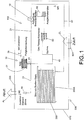
- a house energy center 500 according to the invention in Fig. 1 has a fuel cell unit 200.
- the house energy center 500 can have a lounge ventilation system, of which only one supply air duct 551 and one exhaust air duct 555 are shown in the present case.
- the house energy center 500 has a flushing arrangement 100 for flushing the fuel cell unit 200 on its anode side 200A.
- the flushing arrangement 100 has a flushing channel, which in the present case is formed by a first flushing channel section 20 and a second flushing channel section 21.
- the first 20 and second 21 flushing channel sections can be fluidly connected to one another via a purge valve 10 of the flushing arrangement 100.
- the first flushing channel section 20 is fluidly connected on the one hand to the anode side 200A of the fuel cell unit 200, in this example with a nominal fuel cell power of 1 kW, on the other hand to the purge valve 10.
- the buffer store 30 branches off from the second flushing channel section 21.
- the storage chamber 31 is designed as a bellows.
- the storage chamber 31 designed as a bellows serves for the intermediate storage of a fluid mass to be flushed out of the fuel cell unit 200 in a pulsed manner with a flushing mass flow M1.
- This pulse-like fluid mass flushed out with the flushing mass flow M1 of for example 100 Nl / min over a period of approx. 500 milliseconds can enter the storage chamber 31 designed as a bellows when the purge valve 10 is open, whereby this expands in the process.
- the storage chamber 31, designed as a bellows has a volume of 2.6 L in the expanded state E1.
- the flushing arrangement 100 furthermore has an outflow element 40 which is fluidly connected to the second flushing channel section 21.
- the outflow element 40 is designed for a discharge mass flow M2 of at most 2.5 Nl / min during normal operation and is used to discharge the fluid mass with a discharge mass flow M2 which is significantly lower in amount than the flushing mass flow M1.
- a secondary channel 45 branches off from the second flushing channel section 21, which in the present case is designed in the manner of a siphon.
- a gas-liquid separator 50 and an expansion tank 60 are arranged in the secondary channel 45.
- a fill level sensor 35 is assigned to the buffer store 30, which is designed and arranged in the present case to detect an expansion state of the storage chamber 31.
- the storage chamber 31 is shown expanded by less than 50%, so that the filling level sensor 35, which in the present case is designed as an optical light barrier, does not trigger.
- Supply air ZL can enter a housing section 510 of the house energy system 500 via the supply air duct 551, in the present case the flushing arrangement 100 and fuel cell unit 200 being arranged within the housing section 510 of the house energy system 500.
- Exhaust air AL from the lounge ventilation system (not shown) can be guided to the surroundings via the exhaust air duct 555.
- the outflow element 40 of the flushing arrangement 100 is arranged in such a way that the fluid mass exiting from the outflow element 40 can be discharged to the environment via the exhaust air duct 555.
- a house energy center 500 in Fig. 2 has an electrolysis unit 300 with an attached flushing arrangement 100. Furthermore in Fig. 2 A supply air duct 551 of a lounge ventilation system (not shown) is shown, which enters the housing section 510 of the domestic energy installation 500. Furthermore, the exhaust air duct 555 of a recreation room ventilation system (not shown), from which exhaust air AL from the housing section 510, which is assigned to the electrolysis unit 300, can exit from the house energy center 500, can be seen.
- the house energy center 500 in Fig. 2 has a flushing arrangement 100 for flushing the electrolysis unit 300 on its cathode side 300K.
- the rinsing arrangement 100 has a first 20 and second 21 rinsing channel section which can be fluidly connected to one another via a purge valve 10 of the rinsing arrangement 100.
- the rinsing arrangement 100 also has a buffer store 30 connected downstream of the purge valve 10 with a storage chamber 31, which in the present case is designed as a bellows and is provided for the intermediate storage of a fluid mass to be rinsed out of the electrolysis unit 300 in a pulsed manner with a rinsing mass flow M1.
- the second flushing channel section 21 runs at least in sections through the buffer store 30.
- This fluid mass can be discharged via an outflow element 40, which is fluidly connected to the second flushing channel section 21, with an outlet mass flow M2 that is lower than the flushing mass flow M1.
- the outflow element 40 of the flushing arrangement 100 is arranged in such a way that the fluid mass exiting from the outflow element 40 can be discharged to the environment via the exhaust air duct 555.
- the storage chamber 31 has an internal water separator 32, so that separated water can be returned to a house energy center for further use. In the present case, this takes place via the secondary channel 45.
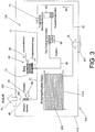
- Fig. 3 shows the arrangement Fig. 1 , in which the outflow element 40 is provided as a recombiner.
- the discharge mass flow M2 flows into the outflow element 40 provided as a recombiner and an air flow M3 flows via a separate fan 41.
- the two material flows are mixed and the hydrogen contained in the discharge mass flow is catalytically converted with oxygen from the air flow M3 to form water and heat.
- the now hydrogen-free, heated product gas is added to the exhaust air AL.
- Fig. 4 serves to explain the function of the flushing arrangement according to the invention on the basis of a mass flow diagram over time.
- a fuel cell unit (not shown) is rinsed at times T1, T2 and T3 with a pulse-like rinsing mass flow M1, M1, M1 ′′.
- a pulse-like rinsing mass flow M1, M1, M1 ′′ There is a pause of 24 seconds each between the individual purges Fig. 3 can be removed, the rinsing mass flows M1, M1, M1 ′′ that are rinsed out in a pulse-like manner each have a rinsing mass flow of 5, for example 96 Nl / min, which is the case, for example, when a purge is a maximum of 0.8 Nl and within 500 milliseconds is discharged on the anode side of a fuel cell unit.
- a respective discharge mass flow M2, M2 'and M3 is shown in the lower part of the figure.
- flushing mass flows each have a flushing mass flow of less than 2 Nl / min.
- a rinse mass flow M2, M2 ', M3 ′′ reaches, for example, a mass flow of 0 L / min, that is, the buffer store is correspondingly discharged and ready for the next rinse mass flow to be expelled in a pulsed manner.
- Fig. 5 shows three expansion states E1, E2, E3 of a storage chamber 31, designed as a bellows, of a buffer tank 30 of a flushing arrangement 100 according to the invention the fault detection of the storage chamber 31 designed as a bellows.
- Figure 5a shows an expansion state E1, which in error-free normal operation, immediately after a purge with 0.8 Nl is emitted in a pulse-like manner with a flushing mass flow, i.e. in a state that occurs at times T1, T2 and T3 in Fig. 3 is shown.
- the non-expanded state E1 is in Figure 5a ) indicated by the correspondingly designated axis and is taken with a fluid mass of 0 to 0.25 Nl (dead volume) in the storage chamber 31 designed as a bellows.
- the storage chamber 31 designed as a bellows is expanded to half of its maximum expansion state. This can be the case, for example, in the event of a software error that can affect the purge rate.
- the level sensor 35 detects the in Figure 5B shown expansion state E2 of the storage chamber 31 designed as a bellows, which has the effect that no further purges are triggered.
- FIG 5c shows the error state of a storage chamber 31 designed as a bellows that is "hanging" in its maximally expanded expansion state E3.
- This expansion state E3 is also detected by the fill level sensor 35. Since the storage chamber 31 designed as a bellows can no longer serve as a damping buffer for a purge that is flushed out in the manner of a pulse, the discharge mass flow M2 increases to an undesirably high level of, for example, 4 NI / min.
- a secondary channel 45 branches off from the second flushing channel section 21 and has a gas-liquid separator 50. Since the secondary channel 45 is designed in the form of a siphon in the present case, it serves as overpressure protection for the storage chamber 31 designed as a bellows.
- Fig. 6 is a buffer storage 30 with an expandable storage chamber 31 designed as a piston storage.
- the flushing mass flow M1 is directed into the liquid-filled storage chamber 31, which in the illustrated embodiment is limited by concentrically arranged and mutually axially movable cylinder elements 31 ', 31 "and displaces the liquid FL Similar to a piston, the inner cylinder element 31 'moves upwards and thereby realizes an expansion of the storage chamber 31.
- a bellows cf. Fig.
- an end plate here the cover plate 32 of the inner cylinder element 31 ', and optionally a spring arrangement (not shown) can generate a defined pressure in the flushing gas volume, which can be emptied again via the outflow element 40 at a desired time interval.
- a spring arrangement not shown
Landscapes
- Chemical & Material Sciences (AREA)
- Engineering & Computer Science (AREA)
- Electrochemistry (AREA)
- Chemical Kinetics & Catalysis (AREA)
- Sustainable Development (AREA)
- Sustainable Energy (AREA)
- Life Sciences & Earth Sciences (AREA)
- Manufacturing & Machinery (AREA)
- General Chemical & Material Sciences (AREA)
- Materials Engineering (AREA)
- Metallurgy (AREA)
- Organic Chemistry (AREA)
- Inorganic Chemistry (AREA)
- Fuel Cell (AREA)
- Electrolytic Production Of Non-Metals, Compounds, Apparatuses Therefor (AREA)
Description
- Die vorliegende Erfindung betrifft eine Spülanordnung zum Spülen (Purgen) einer Brennstoffzelleneinheit auf ihrer Anodenseite und/oder einer Elektrolyseeinheit auf ihrer Kathodenseite. Die vorliegende Erfindung betrifft ebenfalls eine Hausenergiezentrale sowie ein Verfahren zum Betreiben einer Hausenergiezentrale.
- Anordnungen zum Spülen einer Brennstoffzelleneinheit auf ihrer Anodenseite und/oder einer Elektrolyseeinheit auf ihrer Kathodenseite sind grundsätzlich aus dem Stand der Technik bekannt. Ein Spülen ist erforderlich, um unerwünschte Fremdgasanteile, sowie sich lokal in den Zellstrukturen ansammelndes flüssiges Wasser die die Leistungsfähigkeit und die Lebensdauer der Brennstoffzelle und/oder des Elektrolyseurs negativ beeinflussen können, in regelmäßigen Abständen oder abhängig von den Betriebszuständen abzuführen.
- Es ist Aufgabe der vorliegenden Erfindung, eine hinsichtlich H2-Sicherheit, Betriebsverhalten und Auslegung der relevanten Stoffströme verbesserte Spülanordnung, eine Hausenergiezentrale mit einer Spülanordnung sowie ein Verfahren zum Betreiben einer Hausenergiezentrale anzugeben.
- Aus
US 2006/0105224 A1 ist ein Brennstoffzellensystem beschrieben, das Mittel zum Spülen (purgen) des Brennstoffzellenstacks aufweist. - Aus
US 2002/0094469 A1 ist ein Brennstoffzellensystem bekannt, das einen balgenartigen Pufferspeicher aufweist, um ausgespülten Wasserstoff langsamer an die Umgebung abgeben zu können. - Aus
DE 10 2014 103 724 A1 ist eine Brennstoffzellenvorrichtung mit einer Purgevorrichtung und einem Pufferbehälter bekannt. - Aus
US 2005/0214617 A1 ist ein Brennstoffzellensystem mit einem Akkumulator zum Auffangen ausgespülten Anodengases bekannt. - Aus
US 2006/0263658 A1 ist ein Brennstoffzellensystem mit einer Kammer zum zwischenzeitlichen Aufnehmen ausgespülten Wasserstoffs bekannt. - Aus
US 2013/0149627 ist ein Brennstoffzellensystem mit einem Puffertank bekannt, der einen Füllstandsensor für in dem Puffertank sich ansammelndes Wasser aufweist. - Aus
WO 2012/113932 A2 ist ein Lüftungs- und Heizsystem bekannt, bei dem die Abwärme einer Brennstoffzelle zum Wärmen eines Raums genutzt werden kann. - Aus
JP 2001130901 - Bezüglich der Spülanordnung wird die Aufgabe gelöst durch eine Spülanordnung nach Anspruch 1. Der Ablass-Massenstrom, welcher typischerweise großteils aus H2 besteht, kann einem Luftmassenstrom zugemischt werden, so dass das entstehende Gasgemisch eine H2-Konzentration in allen Betriebszuständen deutlich unterhalb der unteren Zündgrenze von H2 in Luft aufweist. Durch diesen Verdünnungseffekt ist ein sicherer Betrieb der Anlage möglich.
- Das Ausströmelement kann als Blende, Drossel, Düse, Strahlpumpe, Venturidüse oder Rekombinator ausgebildet sein. Der Pufferspeicher kann vom zweiten Spülkanalabschnitt abzweigen. Der zweite Spülkanalabschnitt kann zumindest abschnittweise durch den Pufferspeicher verlaufen.
- Die Erfindung schließt die Erkenntnis ein, dass bei einem Purgen gemäß des Standes der Technik, das pulsartig mit einem Spül-Massenstrom erfolgt, typischerweise über Bruchteile einer Sekunde relativ hohe Mengen von Wasserstoff aus einer Brennstoffzelleneinheit und/oder einer Elektrolyseeinheit ausgespült werden. Im Anschluss an einen derartigen pulsartigen Purge wird längere Zeit kein Wasserstoff mehr freigesetzt. Dadurch können bei der Zumischung zur Abluft lokal und temporär kritisch hohe Wasserstoffkonzentrationen, insbesondere auch Konzentrationen über der unteren Zündgrenze, auftreten, die zu einer gefährlichen Knallgasreaktion führen können. Zumindest während des Pulses mit hohem Spül-Massenstrom ist daher der Abluft-Massenstrom zu erhöhen, um einen hinreichenden Verdünnungseffekt zu gewährleisten.
- Dadurch, dass erfindungsgemäß dem Purge-Ventil ein Pufferspeicher mit einer Speicherkammer nachgeschaltet ist, kann die pulsartig mit dem Spül-Massenstrom ausgetragene Fluidmasse mit einem Ablass-Massenstrom, der geringer als der Spül-Massenstrom ist, ausgetragen werden. Vorteilhafterweise ergibt sich dadurch eine Glättung des pulsartigen Spül-Massenstroms, was vorteilhaft zur Vermeidung von kritischen Wasserstoffkonzentrationen bei gleichzeitig niedrigerem Abluft-Massenstrom führt.
- Erfindungsgemäß ist die Speicherkammer expandierbar. Die Speicherkammer ist durch die pulsartig mit dem Spül-Massenstrom aus der Brennstoffzelleneinheit und/oder der Elektrolyseeinheit auszuspülenden Fluidmasse expandierbar. Besonders bevorzugt ist die Speicherkammer als Faltenbalg ausgebildet, der ein jeweiliges Spül-Volumen, d.h. den Spül-Massenstrom multipliziert mit einer Pulsdauer eines Purges, ohne oder mit nur geringfügigem Aufbau von Gegendruck aufnehmen kann. Eine als Faltenbalg ausgebildete Speicherkammer kann ausgebildet sein, durch eine Gravitationskraft, insbesondere ausschließlich durch eine Gravitationskraft einer bevorzugt frei beweglichen Endplatte des Faltenbalgs, in ihren nicht expandierten Zustand zurückbewegt zu werden. Zur gezielten Anpassung der Kraft, die den Faltenbalg in seinen nicht expandierten Zustand zurückbewegt, und damit der Entladezeit und des Druckverlaufes des Faltenbalgpuffers über der Zeit, kann die Gravitationskraft auch durch eine angebrachte Federvorrichtung verstärkt oder teilweise kompensiert sein.
- Um erhöhte Leistungsverluste und Alterungseffekte auszuschließen, ist es vorteilhaft, pro Spülvorgang jeweils ca. 0,75 Nl (Normliter) H2-reiches Gas pro kW Nennleistung der Brennstoffzelleneinheit anodenseitig auszuspülen. Bevorzugt dauert ein pulsartiger Spülvorgang weniger als 0,5 s, vorzugsweise maximal 0,2 s. Es ist ebenfalls vorteilhaft, pro Spülvorgang jeweils ca. 0,75 NI (Normliter) H2-reiches Gas pro kW Nennleistung der Elektrolyseeinheit auszuspülen.
- Im Folgenden, wenn nicht anders erwähnt, soll davon ausgegangen werden, dass eine Auslegung der Spülstrecke hinsichtlich der Brennstoffzelleneinheit-Anforderungen auch für die Elektrolyseeinheit ausreichend ist. Bei deutlich geänderten Leistungsgrößen und Betriebsbedingungen im Gesamtsystem sind die Auslegungen jedoch auch analog über spezielle Elektrolyseeinheit -Spülanforderungen durchführbar.
- Der Druck auf der Anodenseite und damit der Vordruck beim Spül-Prozess ist bei einer Brennstoffzelleneinheit, die luftseitig bei Umgebungsdruck arbeitet, typischerweise bei etwa 300 Millibar.
- Der Spül-Massenstrom und das Spülvolumen für die Brennstoffzelleneinheit kann seitens der Spülanordnung, bei üblicherweise fest eingestelltem Anodendruck, über den Strömungswiderstand des Brennstoffzellen-Purge-Ventils (beispielsweise ein Elektromagnetventil) und/oder die Öffnungszeit während des Pulses einstellbar sein.
- Der Spül-Massenstrom und das Spülvolumen für die Elektrolyseeinheit kann über die Wahl des Kathodendruckes, bei welchem der Spülvorgang beginnt, den Strömungswiderstand des Elektrolyse-Purge-Ventils (beispielsweise ein Elektromagnetventil) und/oder die Öffnungszeit während des Pulses einstellbar sein.
- Das Verhältnis von Abluft-Massenstrom und Ablass-Massenstrom sowie die Effizienz der Vermischung beider Massenströme bestimmen die Konzentration von brennbaren Gasen, insbesondere H2, in der Fortluft. Diese soll aus Sicherheitsgründen deutlich unterhalb der Unteren Zündgrenze von H2 in Luft sein (die UZG von H2 in Luft liegt bei 4%), vorzugsweise unterhalb von ca. 2 %. Bei gegebenem Abluft-Massenstrom kann dies zur limitierenden Größe für den noch erlaubten maximalen Ablass-Massenstrom werden und die gesamte Spülanordnung ist daraufhin zu dimensionieren.
- Über die Parameter Querschnittsfläche des Faltenbalgs, Längen- zu DurchmesserVerhältnisses des Faltenbalgs, Federsteifigkeit des Balgmaterials, Gewicht der frei beweglichen Endplatte, und insbesondere über die Auslegung des Strömungswiderstands des Ausströmelements kann das Lade-/Entladeverhalten, insbesondere der Verlauf des Ablass-Massenstroms über der Zeit ausgelegt sein. Nachfolgend beschriebene Auslegungsdaten des Faltenbalgs und des Ausströmelements können für eine Spülvorrichtung für ein Brennstoffzelleneinheit mit einer Nennleistung von 1 kW gelten.
- Besonders bevorzugt ist ein Durchflusskoeffizient des Ausströmelements größer oder gleich dem des Purge-Ventils.
- Bevorzugt beträgt die Querschnittsfläche des Faltenbalgs 100 bis 150 cm2. Besonders bevorzugt beträgt das Längen- zu Durchmesser-Verhältnis eines aktiven Volumens des Faltenbalgs bei maximaler Auslenkung 1,5 : 1 bis 1 : 1. Die Federsteifigkeit des Balges liegt bevorzugt zwischen 50 und 100 N/m. Das Material des elastischen Teils des Faltenbalges kann vorzugsweise aus einem chemisch stabilen und dauerhaft elastischen Elastomer oder aus einem im Kontakt mit Wasserstoff nicht versprödenden Metall bestehen.
- Das Ausströmelement hat bevorzugt einen im Wesentlichen gleich großen Durchflusskoeffizienten wie das Purge-Ventil. Dies kann beispielsweise über eine Blende mit einem freien Durchmesser von ca. 1 mm erreicht werden. Das Gewicht der frei beweglichen Endplatte beträgt bevorzugt zwischen 0,3 und 0,5 kg. Bevorzugt weist eine als Faltenbalg ausgebildete Speicherkammer in expandiertem Zustand ein Volumen von weniger als 3 L, bevorzugt weniger als 2,6 L auf.
- Bevorzugt ist der Faltenbalg ausgelegt, dass der Überdruck im Faltenbalg gegenüber der Umgebung im Betrieb maximal dem Anoden-Nenndruck entspricht, beispielsweise 300 Millibar beträgt. Besonders bevorzugt ist der Faltenbalg ausgelegt, dass der Überdruck bei Maximalauslenkung kleiner als 100 Millibar beträgt und/oder beim nominalen Betrieb, d.h. bis zu ca. 50 Prozent seiner Maximalauslenkung höchstens 20 Millibar beträgt.
- Das Totvolumen einer als Faltenbalg ausgebildeten Speicherkammer ist bevorzugt aus Sicherheitsgründen minimal ausgeführt. Besonders bevorzugt ist ein Totvolumen einer als Faltenbalg ausgebildeten Speicherkammer kleiner als 250 ml.
- Die Speicherkammer kann als Blasenspeicher oder als Kolbenspeicher (vgl.
Fig. 5 ) ausgebildet sein. Alternativ zu einer expandierbaren Ausbildung der Speicherkammer kann die Speicherkammer als starrer Druckbehälter ausgebildet sein, bei welchem die Speicherkammer derart ausgebildet ist, dass die pulsartig mit dem Spül-Massenstrom aus der Brennstoffzelleneinheit und/oder der Elektrolyseeinheit ausgespülte Fluidmasse zu einem Druckanstieg in der Speicherkammer führt. - In einer bevorzugten Ausgestaltung weist der Pufferspeicher eine Auslassdrossel als Ausströmelement auf, die als Blende ausgebildet sein kann. Die Auslassdrossel kann derart dimensioniert sein, dass beispielsweise eine als Faltenbalg ausgebildete Speicherkammer mit einem Volumen von 2,6 L in expandiertem Zustand innerhalb von wenigstens 30 Sekunden entladen wird.
- Das Ausströmelement kann bevorzugt ein Sintermetallzylinder oder ein Sinterkeramikzylinder oder ein Metallvlies sein, über welches der Ablass-Massenstrom gleichmäßig in die Abluft verteilt wird. Damit wird die Vermischung des ausströmenden wasserstoffhaltigen Gases mit der die Wasserstoff-Konzentration verdünnenden Abluft verbessert. Der vorteilhafte Nenndruckverlust über diese Vorrichtung kann analog zur oben beschriebenen Auslassdrossel dimensioniert sein.
- Das Ausströmelement kann bevorzugt ein katalytisch aktiver Rekombinator sein oder einen solchen aufweisen. Bevorzugt wird diesem ein wasserstoffhaltiger Ablassmassenstrom bei Anwesenheit eines Oxidationskatalysators, vorzugsweise edelmethallhaltige Katalysatoren aus der Platinmetallgruppe, Luft in hohem Überschuss zugeführt, so dass die Rekombination des Wasserstoffs mit dem Luftsauerstoff, bei ca. 0,5% bis 8 % Wasserstoff in Luft, vorzugsweise bei 1% bis 5% Wasserstoff in Luft, kontrolliert und flammenlos zu Wasser unter Freisetzung von Wärme erfolgt.
- Es hat sich als vorteilhaft herausgestellt, wenn dem Rekombinator ein Kompressor zur Versorgung des Rekombinators mit Luft zugeordnet ist, dessen Ansteuerung mit einer Ansteuerung des Purge-Ventils zeitlich gekoppelt ist. Alternativ oder zusätzlich kann die Ansteuerung des Kompressors an den zeitlichen Vorlauf und/oder Nachlauf eines Lüftungsgerät einer Hausenergiezentrale gekoppelt sein. Alternativ oder zusätzlich kann die Ansteuerung des Kompressors an eine Auslass-Temperatur des Ablass-Massenstroms und/oder eines durch ein Lüftungsgerät einer Hausenergiezentrale bewirkten Abluftstroms/Fortluftstroms sein.
- Vorteil der Erfindung ist, dass sich durch die Vergleichmäßigung des Ablass-Massenstromes durch den Pufferspeicher die auftretenden Konzentrationen gut einstellen lassen und die Rekombination erst dadurch mit geringem Regelungsaufwand sicher beherrschbar ist. Damit ist die im Ablass-Massenstrom enthaltenen chemische Energie des Wasserstoffs thermisch im Prozess nutzbar und die Abluft des Systems wird nicht mit Wasserstoff aus dem Spülvorgang belastet.
- Es hat sich als vorteilhaft herausgestellt, wenn das Ausströmelement auf einen Massenstrom von kleiner als 2,5 NI/min pro kW Brennstoffzellen-Nennleistung, bevorzugt höchstens 2,0 Nl/min pro kW Brennstoffzellen-Nennleistung, jeweils im Normbetrieb (fehlerfreier Betrieb des Pufferspeichers) ausgelegt ist.
- Die Spülanordnung kann ausgebildet sein, einen Spül-Volumenstrom auf einen Ablass-Volumenstrom von weniger als 10%, vorzugsweise weniger als 3 % des Spül-Volumenstroms zu reduzieren. Bevorzugt erfolgt ein Austragen des Ablass-Volumenstrom zur Umgebung über einen mindestens 50 Nm3/h großen Abluftstrom/Fortluftstrom. Bevorzugt liegt ein Nenn-Betriebsdruck der Speicherkammer weniger als 50 Millibar, bevorzugt weniger als 20 Millibar über einem Betriebsdruck des Abluftstroms/Fortluftstroms.
- Beim Spülvorgang kann bestimmungsgemäß flüssiges Wasser mit ausgetragen werden. In einer bevorzugten Variante wird das Wasser zunächst vom Gasstrom abgeschieden und danach vorteilhafterweise in den Prozess der Brennstoffzelle und/oder der Elektrolyse zurückgeführt. Die Wasser-Abscheidung kann vorteilhaft im Pufferbehälter realisiert sein, da dort die Strömungsgeschwindigkeiten des Trägergases für eine Abscheidung der Flüssigkeit über Gravitationskräfte vorteilhaft gering sind.
- Vorzugsweise hat der Pufferbehälter mindestens je einen Eingang und/oder einen Ausgang für das Spülgas. Flüssigkeit, die zusammen mit dem wasserstoffhaltigen Spülgas über den Einlass mit hoher Strömungsgeschwindigkeit in den Pufferbehälter gelangt, kann dort vorzugsweise gravimetrisch oder/und durch strömungsführende und/oder tropfenabscheidende Einbauten und/oder bei entsprechender tangentialer Einleitung durch Zentrifugalkräfte oder durch andere gängige Verfahren nach dem Stand der Technik vom Gasstrom abgeschieden werden. Die Flüssigkeit kann vorzugsweise am Boden des Pufferspeichers gesammelt und geschlossen über den Flüssigkeitsauslass abgeleitet und vorzugsweise dem Prozess wieder zugeführt werden.
- Die Spülanordnung kann an einen Gas-Flüssig-Abscheider, vorzugsweise an einen in der Elektrolyseeinheit vorhandenen Sauerstoffabscheider oder an den ebenfalls dort vorhandenen Wassernachfüllbehälter und/oder einen Ausgleichsbehälter angeschlossen sein und/oder einen solchen aufweisen.
- Der Gas-Flüssig-Abscheider und/oder der Ausgleichsbehälter kann in einem von dem zweiten Spülabschnitt abzweigenden Nebenkanal angeordnet sein. Bevorzugt ist ein Ausgleichsbehälter einem Gas-Flüssig-Abscheider nachgeschaltet. Es hat sich als vorteilhaft herausgestellt, wenn der Nebenkanal siphonartig ausgebildet ist. Ein siphonartig ausgebildeter Nebenkanal kann als Überdruckschutz für den Pufferspeicher dienen, dessen Wassersäule bei zu hohem Überdruck des Wasserstoffs in den Gas-Flüssig-Abscheider drücken kann. Der dann über Nebenkanal abfließende Wasserstoff führt zu einer Druckentlastung des Pufferspeichers. In einer bevorzugten Variante kann in den siphonartig ausgebildeten Nebenkanal auch eine Gas-Flüssig-Abscheidung integriert sein. Durch eine derartige Ausgestaltung der Spülanordnung kann auch das Wasser aus dem Spülvorgang wieder zur Nutzung in das Elektrolysemodul zurückgeführt werden.
- Die Spülanordnung weist einen Füllstandssensor auf, insbesondere einen dem Pufferspeicher zugeordneten Füllstandssensor. Der Füllstandssensor ist erfindungsgemäß zum Detektieren eines Expansionszustands der Speicherkammer ausgebildet und angeordnet sein. Der Füllstandssensor kann vorzugsweise als optischer Sensor oder magnetischer Sensor oder als Ultraschallsensor ausgebildet sein und ist vorzugsweise für den Betrieb in einer potentiell wasserstoffhaltigen Umgebung zulässig. Bevorzugt ist der Füllstandssensor derart angeordnet und eingestellt, dass dieser bei einem Expansions zustand von bevorzugt maximal 80 % des Maximalvolumens, welcher bei einem fehlerhaft nicht mehr schließenden Magnetventil auftreten kann, eine Sicherheitskette auslöst und weiteres Ausströmen von Wasserstoff verhindert. Über den Füllstandssensor kann in einem bevorzugten Verfahren auch die Qualität des Spülvorgangs überwacht und/oder der Spülvorgang von einem gesteuerten Prozess über die Erfassung des tatsächlich gespülten Volumens in einen geregelt Prozess überführt werden.
- In einer weiteren bevorzugten Ausführung kann ein weiterer oder weitere Pufferspeicher mit jeweils einer expandierbaren Speicherkammer von der Spülanordnung umfasst sein. Wenigstens zwei der Speicherkammern können, bezüglich eines Durchströmens durch den Spül-Massenstrom, derart fluidverbunden sein, dass ein paralleles oder serielles Durchströmen der Speicherkammern realisiert wird. Vorteil dieser Anordnung ist, dass unterschiedliche Parameter durch die Auslegung eingestellt werden können, welche z.B. ermöglichen: eine zweistufige, verbesserte Wasserabscheidung, welche insbesondere bei der seriellen Fluidverbindung realisierbar ist und/oder eine Redundanz oder Reserve und/oder eine Detektion eines Fehlerfalls, beispielsweise durch Überwachung des Ansprechens des weiteren (redundanten) Pufferspeicher. Bei zwei- oder mehrstufiger Pufferung können beispielsweise die Pufferspeicher per Magnetventil individuell zu- und weggeschaltet werden oder die Pufferspeicher können durch eine unterschiedliche Auslegung erst bei unterschiedlichen Drücken ansprechen.
- Bezüglich der Hausenergiezentrale wird die Aufgabe gelöst durch eine Hausenergiezentrale mit wenigstens einer Brennstoffzelleneinheit und/oder Elektrolyseeinheit, wobei die Hausenergiezentrale eine vorbeschriebene Spülanordnung aufweist, die zum Spülen der Brennstoffzelleneinheit auf ihrer Anodenseite und/oder der Elektrolyseeinheit auf ihrer Kathodenseite angeschlossen ist.
- In einer bevorzugten Ausgestaltung der Hausenergiezentrale weist diese ein Aufenthaltsraum-Lüftungssystem auf. Das Aufenthaltsraum-Lüftungssystem kann einen Zuluftkanal aufweisen, über den Zuluft in das Aufenthaltsraum-Lüftungssystem führbar ist. Das Aufenthaltsraum-Lüftungssystem kann einen Raumzuluftkanal aufweisen, über den Luft vom Aufenthaltsraum-Lüftungssystem in einen Aufenthaltsraum, beispielsweise ein Wohnzimmer, führbar ist. Das Aufenthaltsraum-Lüftungssystem kann einen Abluftkanal aufweisen, über den Abluft aus dem Aufenthaltsraum-Lüftungssystem zur Umgebung führbar ist. Bevorzugt ist das Ausströmelement der Spülanordnung derart angeordnet, dass die aus dem Ausströmelement austretende Fluidmasse über den Abluftkanal zur Umgebung austragbar ist.
- Alternativ kann über das Ausströmelement die austretende Fluidmasse auch in die Kathodenluft der Brennstoffzelleneinheit zugemischt werden. Der Wasserstoffanteil wird dann beim Durchströmen der Kathode am sich dort befindlichen Katalysator zum Großteil mit Sauerstoff katalytisch umgesetzt. Es entsteht dabei Wasserdampf und Wärme, welche die Lufttemperatur erhöht und dadurch für die Beheizung der Raumluft zur Verfügung steht. .
- Die Hausenergiezentrale ist bevorzugt derart ausgebildet und/oder betreibbar, dass ein Nenn-Betriebsdruck der Speicherkammer weniger als 50 Millibar, bevorzugt weniger als 20 Millibar, weiter bevorzugt weniger als 10 Millibar über einem Betriebsdruck des über den Abluftkanal geführten Abluftstroms liegt. Die die Anodenseite der Brennstoffzelleneinheit ist bevorzugt auf einen Betriebsdruck von höchstens 300 Millibar ausgelegt.
- Die Hausenergiezentrale mit der Spülanordnung kann entsprechend der vorbeschriebenen Spülanordnung weiter ausgestaltet sein.
- Bezüglich des Verfahrens zum Betreiben einer Hausenergiezentrale wird die Aufgabe durch ein Verfahren gelöst mit dem Schritt: Austragen der Fluidmasse über den Abluftkanal zur Umgebung zusammen mit einer Abluft. Das erfindungsgemäße Verfahren wird mit einer vorbeschriebenen Hausenergiezentrale durchgeführt. Eine weitere bevorzugte Anordnung stellt dar, dass die Spülanordnung in Größe und Konfiguration so ausgelegt ist, dass sie gemeinsam für die Brennstoffzelleneinheit und die Elektrolyseeinheit verwendbar ist, falls beide Komponenten gleichzeitig im System vorhanden sind. Typischerweise werden die Brennstoffzelleneinheit und die Elektrolyseeinheit zwar nicht gleichzeitig betrieben, die Anforderungen, die die beide Komponenten an die Spülvorrichtung stellen, sind in der Regel unterschiedlich können aber durch die Einstellung der hier beschriebenen Parameter gezielt erfüllt werden.
- Es hat sich als vorteilhaft herausgestellt, wenn die Fluidmasse mit einem Ablass-Massenstrom von höchstens 2,5 Nl/min pro kW Brennstoffzellen-Nennleistung und die Abluft mit einem Volumenstrom von wenigstens 100 m3/h ausgetragen werden. Das Verfahren kann ein Purgen in Intervallen vorsehen, wobei bevorzugt pro Purge maximal 0,8 Nl pro kW Brennstoffzellen-Nennleistung als Fluidmasse aus einer Brennstoffzelleneinheit und/oder einer Elektrolyseeinheit mit einem Spül-Massenstrom austreten. Bevorzugt liegt zwischen den Intervallen eine Spülpause von wenigstens 20 Sekunden, bevorzugt eine Spülpause von mehr als 30 Sekunden.
- Bevorzugt sieht das Verfahren vor, dass pro Purge maximal 0,8 Nl pro kW Brennstoffzellen-Nennleistung im Pufferspeicher aufgenommen und über das Ausströmelement mit einem Massenstrom von ungefähr 2 Nl/min pro kW Brennstoffzellen-Nennleistung ausgetragen werden.
- Die Ausführungsbeispiele der vorliegenden Erfindung werden im Folgenden beispielhaft unter Bezugnahme auf die beigefügten Figuren erläutert. Es zeigt:
-
Fig. 1 eine schematische Darstellung eines ersten Ausführungsbeispiels einer Hausenergiezentrale mit einer Spülanordnung; -
Fig. 2 eine schematische Darstellung eines zweiten Ausführungsbeispiels einer Hausenergiezentrale mit einer Spülanordnung; -
Fig. 3 eine schematische Darstellung des dritten Ausführungsbeispiels einer Hausenergiezentrale mit Rekombinator als Ausströmelement; -
Fig. 4 eine schematische Darstellung eines zeitlichen Verlaufs von Spül-Massenstrom und Ablass-Massenstrom; -
Fig. 5 eine schematische Darstellung verschiedener Zustände eines Pufferspeichers; und -
Fig. 6 eine schematische Darstellung eines Pufferspeichers mit expandierbarer Speicherkammer. - Eine erfindungsgemäße Hausenergiezentrale 500 in
Fig. 1 weist eine Brennstoffzelleneinheit 200 auf. Die Hausenergiezentrale 500 kann ein Aufenthaltsraum-Lüftungssystem aufweisen, von dem vorliegend nur ein Zuluftkanal 551 und ein Abluftkanal 555 gezeigt ist. Des Weiteren weist die Hausenergiezentrale 500 eine Spülanordnung 100 zum Spülen der Brennstoffzelleneinheit 200 auf ihrer Anodenseite 200A auf. - Die Spülanordnung 100 weist einen Spülkanal auf, der vorliegend durch einen ersten Spülkanalabschnitt 20 und einen zweiten Spülkanalabschnitt 21 gebildet ist. Der erste 20 und zweite 21 Spülkanalabschnitt sind über ein Purge-Ventil 10 der Spülanordnung 100 miteinander fluidverbindbar. Der erste Spülkanalabschnitt 20 ist einerseits mit der Anodenseite 200A der Brennstoffzelleneinheit 200, in diesem Beispiel mit einer Brennstoffzellen-Nennleistung von 1 kW, andererseits mit dem Purge-Ventil 10 fluidverbunden. Dem Purge-Ventil 10 nachgeschaltet und über den zweiten Spülkanalabschnitt 21 mit dem Purge-Ventil 10 fluidverbunden ist ein Pufferspeicher 30 mit einer Speicherkammer 31. Der Pufferspeicher 30 zweigt vom zweiten Spülkanalabschnitt 21 ab.
- Vorliegend ist die Speicherkammer 31 als Faltenbalg ausgebildet. Die als Faltenbalg ausgebildete Speicherkammer 31 dient zur Zwischenspeicherung einer pulsartig mit einem Spül-Massenstrom M1 aus der Brennstoffzelleneinheit 200 auszuspülenden Fluidmasse. Diese impulsartige mit dem Spül-Massenstrom M1 von beispielsweise 100 Nl/min über einen Zeitraum von ca. 500 Millisekunden ausgespülte Fluidmasse kann bei geöffnetem Purge-Ventil 10 in die als Faltenbalg ausgebildete Speicherkammer 31 eintreten, wobei diese dabei expandiert. Die als Faltenbalg ausgebildete Speicherkammer 31 weist in expandiertem Zustand E1 ein Volumen von 2,6 L auf.
- Die Spülanordnung 100 weist des Weiteren ein Ausströmelement 40 auf, das mit dem zweiten Spülkanalabschnitt 21 fluidverbunden ist. Das Ausströmelement 40 ist auf einen Ablass-Massenstrom M2 von höchstens 2,5 Nl/min bei Normalbetrieb ausgelegt und dient dem Auslass der Fluidmasse mit einem Ablass-Massenstrom M2, der betragsmäßig deutlich geringer ist als der Spül-Massenstrom M1.
- Vom zweiten Spülkanalabschnitt 21 zweigt ein Nebenkanal 45 ab, der vorliegend siphonartig ausgebildet ist. Im Nebenkanal 45 angeordnet sind ein Gas-Flüssig-Abscheider 50 und ein Ausgleichsbehälter 60.
- Dem Pufferspeicher 30 ist ein Füllstandssensor 35 zugeordnet, der vorliegend zum Detektieren eines Expansionszustands der Speicherkammer 31 ausgebildet und angeordnet ist. Im vorliegenden Fall ist die Speicherkammer 31 um weniger als 50 % expandiert dargestellt, sodass der Füllstandssensor 35, der vorliegend als optische Lichtschranke ausgebildet ist, nicht auslöst.
- Über den Zuluftkanal 551 kann Zuluft ZL in einen Gehäuseabschnitt 510 der Hausenergieanlage 500 eintreten, wobei vorliegend Spülanordnung 100 und Brennstoffzelleneinheit 200 innerhalb des Gehäuseabschnitts 510 der Hausenergieanlage 500 angeordnet sind. Über den Abluftkanal 555 ist Abluft AL aus dem Aufenthaltsraum-Lüftungssystem (nicht gezeigt) zur Umgebung führbar. Das Ausströmelement 40 der Spülanordnung 100 ist derart angeordnet, dass die aus dem Ausströmelement 40 austretende Fluidmasse über den Abluftkanal 555 zur Umgebung austragbar ist.
- Eine Hausenergiezentrale 500 in
Fig. 2 weist eine Elektrolyseeinheit 300 mit angeschlossener Spülanordnung 100 auf. Des Weiteren inFig. 2 gezeigt ist ein Zuluftkanal 551 eines nicht gezeigten Aufenthaltsraum-Lüftungssystems, der in den Gehäuseabschnitt 510 der Hausenergieanlage 500 eintritt. Des Weiteren ersichtlich ist der Abluftkanal 555 eines nicht gezeigten Aufenthaltsraum-Lüftungssystems, aus dem Abluft AL aus dem Gehäuseabschnitt 510, der der Elektrolyseeinheit 300 zugeordnet ist, aus der Hausenergiezentrale 500 austreten kann. - Die Hausenergiezentrale 500 in
Fig. 2 weist eine Spülanordnung 100 zum Spülen der Elektrolyseeinheit 300 auf ihrer Kathodenseite 300K auf. Die Spülanordnung 100 weist einen ersten 20 und zweiten 21 Spülkanalabschnitt auf, die über ein Purge-Ventil 10 der Spülanordnung 100 miteinander fluidverbindbar sind. Die Spülanordnung 100 weist ebenfalls einen dem Purge-Ventil 10 nachgeschalteten Pufferspeicher 30 mit einer Speicherkammer 31 auf, die vorliegend als Faltenbalg ausgebildet ist und der Zwischenspeicherung einer pulsartig mit einem Spül-Massenstrom M1 aus der Elektrolyseeinheit 300 auszuspülenden Fluidmasse vorgesehen ist. Der zweiten Spülkanalabschnitt 21 verläuft zumindest abschnittweise durch den Pufferspeicher 30. - Diese Fluidmasse kann über eine mit dem zweiten Spülkanalabschnitt 21 fluidverbundene Ausströmelement 40 mit einem Ablass-Massenstrom M2, der geringer als der Spül-Massenstrom M1 ist, ausgetragen werden.
- Vorliegend ist das Ausströmelement 40 der Spülanordnung 100 derart angeordnet, dass die aus dem Ausströmelement 40 austretende Fluidmasse über den Abluftkanal 555 zur Umgebung austragbar ist.
- Die Speicherkammer 31 weist einen innenliegenden Wasserabscheider 32 aufweist, so dass abgeschiedenes Wasser einer Hausenergiezentrale zur weiteren Nutzung zurückgeführt werden kann. Dies erfolgt vorliegend über den Nebenkanal 45.
-
Fig. 3 zeigt die Anordnung ausFig. 1 , bei der das Ausströmelement 40 als Rekombinator bereitgestellt ist. In das als Rekombinator bereitgestellte Ausströmelement 40 strömt der Ablass-Massenstrom M2 und über einen separaten Lüfter 41 ein Luftstrom M3. Im Inneren des Rekombinators werden die beiden Stoffströme vermischt und der im Ablass-Massenstrom enthaltene Wasserstoff mit Sauerstoff aus dem Luftstrom M3 katalytisch zu Wasser und Wärme umgesetzt. Das nun wasserstofffreie, erwärmte Produktgas wird der Abluft AL zugemischt. -
Fig. 4 dient der Erläuterung der Funktion der erfindungsgemäßen Spülanordnung anhand eines zeitlichen Massenstromverlaufsdiagramms. - Eine nicht gezeigte Brennstoffzelleneinheit wird in den Zeitpunkten T1, T2 und T3 jeweils mit einem pulsartigen Spül-Massenstrom M1, M1, M1" gespült. Zwischen den einzelnen Purges liegt eine Pause von jeweils 24 sek. Wie der
Fig. 3 entnommen werden kann, weisen die pulsartig ausgespülten Spül-Massenströme M1, M1 M1" jeweils einen Spül-Massenstrom von 5 exemplarisch 96 Nl/min auf, was beispielsweise der Fall ist, wenn ein Purge maximal 0,8 Nl beträgt und innerhalb von 500 Millisekunden an der Anodenseite einer Brennstoffzelleneinheit ausgetragen wird. Ein jeweiliger Ablass-Massenstrom M2, M2' und M3" ist im unteren Teil der Fig. gezeigt. Diese Spül-Massenströme weisen jeweils einen Spül-Massenstrom von unter 2 Nl/min auf. Zur Hälfte eines Intervalls zwischen zwei Purges erreicht ein Spül-Massenstrom M2, M2', M3" beispielhaft einen Massenstrom von 0 L/min, das heißt der Pufferspeicher ist entsprechend entladen und für den nächsten pulsartig auszutreibenden Spül-Massenstrom bereit. -
Fig. 5 zeigt drei Expansionszustände E1, E2, E3 einer als Faltenbalg ausgebildeten Speicherkammer 31 eines Pufferspeichers 30 einer erfindungsgemäßen Spülanordnung 100. Gezeigt ist ebenfalls ein dem Pufferspeicher 30 zugeordneter Füllstandssensor 35, vorliegend in Form einer Lichtschranke, zum Detektieren eines jeweiligen Expansionszustands der Speicherkammer 31, vorliegend insbesondere der Fehlerdetektion der als Faltenbalg ausgebildeten Speicherkammer 31. -
Fig. 5a ) zeigt einen Expansionszustand E1, der im fehlerfreien Normalbetrieb, unmittelbar nach Aufnahme eines pulsartig mit einem Spül-Massenstrom abgegebenen Purges mit 0,8 Nl, also in einem Zustand, der zum Zeitpunkt T1, T2 und T3 inFig. 3 gezeigt ist. Der nicht expandierte Zustand E1 ist inFig. 5a ) durch die entsprechend bezeichnete Achse angedeutet und wird eingenommen bei einer Fluidmasse von 0 bis 0,25 Nl (Totvolumen) in der als Faltenbalg ausgebildeten Speicherkammer 31. - Wie aus
Fig. 5b ) ersichtlich ist, ist die als Faltenbalg ausgebildete Speicherkammer 31 auf die Hälfte ihres maximalen Expansionszustandes expandiert. Dies kann beispielsweise bei einem Softwarefehler, der die Purgerate beeinflussen kann, der Fall sein. Der Füllstandssensor 35 detektiert den inFig. 5B gezeigten Expansionszustand E2 der als Faltenbalg ausgebildeten Speicherkammer 31, wodurch bewirkt wird, dass keine weiteren Purges ausgelöst werden. - In
Fig. 5c ) ist der Fehlerzustand einer in ihrem maximal expandierten Expansionszustand E3 "hängenden", als Faltenbalg ausgebildeten Speicherkammer 31 dargestellt. Auch dieser Expansionszustand E3 wird durch den Füllstandssensor 35 detektiert. Da die als Faltenbalg ausgebildete Speicherkammer 31 nunmehr nicht als Dämpfungspuffer für einen impulsartig ausgespülten Purge dienen kann, steigt der Ablass-Massenstrom M2 auf ein unerwünscht hohes Maß von beispielsweise 4 NI/min. Um diesen unerwünschten Zustand abzusichern, zweigt vom zweiten Spülkanalabschnitt 21 ein Nebenkanal 45 auf, der einen Gas-Flüssig-Abscheider 50 aufweist. Da der Nebenkanal 45 vorliegend siphonartig ausgebildet ist, dient er als Überdruckschutz für die als Faltenbalg ausgebildete Speicherkammer 31. - In
Fig. 6 ist ein Pufferspeicher 30 mit expandierbarer als Kolbenspeicher ausgebildeter Speicherkammer 31. Der Spül-Massenstrom M1 wird in die flüssigkeitsbefüllte Speicherkammer 31 geleitet, welche im gezeigten Ausführungsbeispiel von konzentrisch angeordneten und gegeneinander axial beweglichen Zylinderelementen 31', 31" begrenzt wird und verdrängt dabei die Flüssigkeit FL. Ähnlich einem Kolben bewegt sich das innere Zylinderelement 31' nach oben und realisiert dadurch eine Expansion der Speicherkammer 31. Wie bei einem Faltenbalg (vgl.Fig. 5 ) kann durch eine Endplatte, hier die Deckplatte 32 des innere Zylinderelement 31', sowie optional durch eine Federanordnung (nicht gezeigt) ein definierter Druck im Spülgas-Volumen erzeugt werden, der über das Ausströmelement 40 in einem gewünschten Zeitintervall wieder geleert werden kann. Im gezeigten Ausführungsbeispiel derFig. 6 ist auch die Funktion einer Gas-/Flüssigkeits-Abscheidung realisiert.
Claims (17)
- Spülanordnung (100) zum Spülen (Purgen) einer Brennstoffzelleneinheit (200) auf deren Anodenseite (200A) und/oder einer Elektrolyseeinheit (300) auf deren Kathodenseite (300K), wobei die Spülanordnung (100) einen Spülkanal (20, 21), mit einem ersten (20) und einem zweiten (21) Spülkanalabschnitt aufweist, die über ein Purge-Ventil (10) der Spülanordnung (100) miteinander fluidverbindbar sind, und mit einem mit dem Spülkanal (20, 21) fluidverbundenen und dem Purge-Ventil (10) nachgeschalteten Pufferspeicher (30) mit einer Speicherkammer (31), die zur Zwischenspeicherung einer pulsartig mit einem Spül-Massenstrom (M1) aus der Brennstoffzelleneinheit (200) und/oder der Elektrolyseeinheit (300) auszuspülenden Fluidmasse vorgesehen ist, sodass diese Fluidmasse mit einem Ablass-Massenstrom (M2), der geringer als der Spül-Massenstrom (M1) ist, aus einem mit dem zweiten Spülkanalabschnitt (21) fluidverbundenen Ausströmelement (40) ablassbar ist, wobei die Speicherkammer (31) durch die pulsartig mit den Spül-Massenstrom (M1) aus der Brennstoffzelleneinheit (200) und/oder der Elektrolyseeinheit (300) auszuspülenden Fluidmasse expandierbar ist und
dem Pufferspeicher (30) ein Füllstandsensor (35) zugeordnet ist, der zum Detektieren eines Expansionszustands der Speicherkammer (31) ausgebildet und angeordnet ist. - Spülanordnung (100) nach Anspruch 1, dadurch gekennzeichnet, dass die Speicherkammer (31) als Faltenbalg oder Kolbenspeicher oder Blasenspeicher oder Rollmembranspeicher ausgebildet ist.
- Spülanordnung (100) nach Anspruch 2, dadurch gekennzeichnet, dass die als Faltenbalg ausgebildete Speicherkammer (31) ausgebildet ist durch Gravitationskraft in ihren nicht expandierten Zustand (E0) zurückbewegt zu werden.
- Spülanordnung (100) nach Anspruch 2 oder 3, dadurch gekennzeichnet, dass die Faltenbalg ausgebildete Speicherkammer (31) in expandiertem Zustand (E1) ein Volumen von weniger als 3 Liter aufweist.
- Spülanordnung (100) nach wenigstens einem der vorangehenden Ansprüche, dadurch gekennzeichnet, dass die Speicherkammer einen innenliegenden Wasserabscheider aufweist, so dass abgeschiedenes Wasser einer Hausenergiezentrale zur weiteren Nutzung zurückgeführt werden kann.
- Spülanordnung (100) nach wenigstens einem der vorangehenden Ansprüche, dadurch gekennzeichnet, dass das Ausströmelement (40) auf einen Ablass-Massenstrom (M2) von höchstens 2,5 Nl/min pro kW Brennstoffzellen-Nennleistung ausgelegt ist.
- Spülanordnung (100) nach wenigstens einem der vorangehenden Ansprüche, gekennzeichnet durch einen Gas-Flüssig-Abscheider (50) und/oder einen Ausgleichsbehälter (60), die in einem von dem zweiten Spülkanalabschnitt (21) abzweigenden Nebenkanal (45) der Spülanordnung (100) angeordnet sind.
- Spülanordnung (100) nach Anspruch 7, dadurch gekennzeichnet, dass der Nebenkanal (45) syphonartig ausgebildet ist.
- Spülanordnung (100) nach wenigstens einem der vorangehenden Ansprüche, dadurch gekennzeichnet, dass das Ausströmelement (40) ein katalytisch aktiver Rekombinator ist oder einen solchen aufweist.
- Spülanordnung (100) nach Anspruch 9, dadurch gekennzeichnet, dass dem Rekombinator ein Kompressor zur Versorgung des Rekombinators mit Luft zugeordnet ist, dessen Ansteuerung mit einer Ansteuerung des Purge-Ventils (10) zeitlich gekoppelt ist.
- Spülanordnung (100) nach wenigstens einem der vorangehenden Ansprüche, dadurch gekennzeichnet, dass ein Durchflusskoeffizient des Ausströmelements (40) größer oder gleich dem des Purge-Ventils (10) ist.
- Hausenergiezentrale (500) mit wenigstens einer Brennstoffzelleneinheit (200) und/oder Elektrolyseeinheit (300), dadurch gekennzeichnet, dass die Hausenergiezentrale (500) eine Spülanordnung (100) nach einem der vorangehenden Ansprüche aufweist, die zum Spülen der Brennstoffzelleneinheit (200) auf ihrer Anodenseite (200A) und/oder der Elektrolyseeinheit (300) auf ihrer Kathodenseite (300K) angeschlossen ist.
- Hausenergiezentrale (500) nach Anspruch 12, gekennzeichnet durch ein Aufenthaltsraum-Lüftungssystem mit einem Außenzuluftkanal (551,) über den Zuluft in das Aufenthaltsraum-Lüftungssystem führbar ist, einem Raumzuluftkanal über den Luft vom Aufenthaltsraum-Lüftungssystem in einen Aufenthaltsraum führbar und mit einem Abluftkanal (555) über den Abluft aus dem Aufenthaltsraum-Lüftungssystem zur Umgebung führbar ist, wobei das Ausströmelement (40) der Spülanordnung (100) derart angeordnet ist, dass die aus dem Ausströmelement (40) austretende Fluidmasse über den Abluftkanal (555) zur Umgebung austragbar ist.
- Hausenergiezentrale (500) nach Anspruch 12 oder 13, dadurch gekennzeichnet, dass ein Nenn-Betriebsdruck der Speicherkammer (31) weniger als 50 Millibar, bevorzugt weniger als 20 Millibar, weiter bevorzugt weniger als 10 Millibar über einem Betriebsdruck des über den Abluftkanal (555) geführten Abluftstroms liegt.
- Hausenergiezentrale (500) nach einem der Ansprüche 12 bis 14, dadurch gekennzeichnet, dass die Anodenseite (200A) der Brennstoffzelleneinheit (200) auf einen Betriebsdruck von höchstens 300 Millibar ausgelegt ist.
- Verfahren zum Betreiben einer Hausenergiezentrale (500) nach einem der Ansprüche 12 bis 15, aufweisend den Schritt: Austragen der Fluidmasse über den Abluftkanal (555) zur Umgebung zusammen mit einer Abluft.
- Verfahren nach Anspruch 16, wobei die Fluidmasse mit Ablass-Massenstrom von höchstens 2,5 Nl/min pro kW Brennstoffzellen-Nennleistung und/oder die Abluft mit einem Volumenstrom von wenigstens 500 m3/h ausgetragen wird.
Priority Applications (1)
| Application Number | Priority Date | Filing Date | Title |
|---|---|---|---|
| PL16801220T PL3380652T3 (pl) | 2015-11-25 | 2016-11-24 | Dynamiczna komora czyszcząca |
Applications Claiming Priority (2)
| Application Number | Priority Date | Filing Date | Title |
|---|---|---|---|
| DE102015120456 | 2015-11-25 | ||
| PCT/EP2016/078687 WO2017089466A1 (de) | 2015-11-25 | 2016-11-24 | Dynamische purgekammer |
Publications (2)
| Publication Number | Publication Date |
|---|---|
| EP3380652A1 EP3380652A1 (de) | 2018-10-03 |
| EP3380652B1 true EP3380652B1 (de) | 2021-08-25 |
Family
ID=57394580
Family Applications (1)
| Application Number | Title | Priority Date | Filing Date |
|---|---|---|---|
| EP16801220.1A Active EP3380652B1 (de) | 2015-11-25 | 2016-11-24 | Dynamische purgekammer |
Country Status (7)
| Country | Link |
|---|---|
| US (1) | US10886546B2 (de) |
| EP (1) | EP3380652B1 (de) |
| CN (1) | CN108474126B (de) |
| DK (1) | DK3380652T3 (de) |
| ES (1) | ES2897776T3 (de) |
| PL (1) | PL3380652T3 (de) |
| WO (1) | WO2017089466A1 (de) |
Cited By (3)
| Publication number | Priority date | Publication date | Assignee | Title |
|---|---|---|---|---|
| EP4317761A1 (de) | 2022-08-03 | 2024-02-07 | HPS Home Power Solutions AG | Speichervorrichtung zum speichern von gas |
| DE102022130105A1 (de) | 2022-08-03 | 2024-02-08 | Hps Home Power Solutions Ag | Speichervorrichtung zum Speichern von Gas |
| EP4570964A1 (de) | 2023-12-13 | 2025-06-18 | HPS Home Power Solutions AG | Spülvorrichtung zum zwischenspeichern eines gasförmigen mediums aus einem spülvorgang |
Families Citing this family (5)
| Publication number | Priority date | Publication date | Assignee | Title |
|---|---|---|---|---|
| DE102018133201A1 (de) * | 2018-12-20 | 2020-06-25 | Hps Home Power Solutions Gmbh | Spülsystem und dessen Verwendung in einem Energiesystem |
| DE102018133203A1 (de) | 2018-12-20 | 2020-06-25 | Hps Home Power Solutions Gmbh | Spülsystem und Verfahren zu dessen Überwachung |
| AT522522B1 (de) | 2019-05-09 | 2021-06-15 | Avl List Gmbh | Brennstoffzellensystem und Verfahren zum Entfernen von Wasser aus dem Brennstoffzellensystem |
| JP7298541B2 (ja) * | 2020-05-19 | 2023-06-27 | トヨタ自動車株式会社 | 燃料電池システム |
| DE102023211003A1 (de) | 2023-11-07 | 2025-05-08 | Robert Bosch Gesellschaft mit beschränkter Haftung | Elektrochemisches System und Verfahren zum Spülen eines solchen elektrochemischen Systems |
Citations (1)
| Publication number | Priority date | Publication date | Assignee | Title |
|---|---|---|---|---|
| JP2001130901A (ja) * | 1999-11-02 | 2001-05-15 | Mitsubishi Corp | 水素エネルギ供給装置 |
Family Cites Families (8)
| Publication number | Priority date | Publication date | Assignee | Title |
|---|---|---|---|---|
| JP4470346B2 (ja) * | 2001-01-18 | 2010-06-02 | トヨタ自動車株式会社 | 車載用燃料電池システムおよび水素オフガス排出方法 |
| US20060105244A1 (en) * | 2002-06-08 | 2006-05-18 | Kejha Joseph B | Lithium based electrochemical devices having a ceramic separator glued therein by an ion conductive adhesive |
| JP4649861B2 (ja) | 2003-09-09 | 2011-03-16 | トヨタ自動車株式会社 | 燃料電池システム |
| US7651806B2 (en) * | 2004-03-26 | 2010-01-26 | Gm Global Technology Operations, Inc. | Non-flammable exhaust enabler for hydrogen powered fuel cells |
| DE102004055158B4 (de) * | 2004-11-16 | 2015-07-16 | Volkswagen Ag | Brennstoffzellensystem und Verfahren zum Betreiben eines Brennstoffzellensystems |
| CN103081196B (zh) * | 2010-10-21 | 2015-05-13 | 日产自动车株式会社 | 燃料电池系统的运转方法 |
| DE102011076650A1 (de) * | 2011-02-25 | 2012-10-04 | Heliocentris Energiesysteme Gmbh | Lüftungs- und Heizsystem |
| DE102014103724A1 (de) * | 2014-03-19 | 2015-09-24 | Deutsches Zentrum für Luft- und Raumfahrt e.V. | Brennstoffzellenvorrichtung und Verfahren zum Betreiben einer Brennstoffzellenvorrichtung |
-
2016
- 2016-11-24 ES ES16801220T patent/ES2897776T3/es active Active
- 2016-11-24 US US15/777,979 patent/US10886546B2/en active Active
- 2016-11-24 PL PL16801220T patent/PL3380652T3/pl unknown
- 2016-11-24 CN CN201680075623.2A patent/CN108474126B/zh active Active
- 2016-11-24 DK DK16801220.1T patent/DK3380652T3/da active
- 2016-11-24 WO PCT/EP2016/078687 patent/WO2017089466A1/de not_active Ceased
- 2016-11-24 EP EP16801220.1A patent/EP3380652B1/de active Active
Patent Citations (1)
| Publication number | Priority date | Publication date | Assignee | Title |
|---|---|---|---|---|
| JP2001130901A (ja) * | 1999-11-02 | 2001-05-15 | Mitsubishi Corp | 水素エネルギ供給装置 |
Cited By (3)
| Publication number | Priority date | Publication date | Assignee | Title |
|---|---|---|---|---|
| EP4317761A1 (de) | 2022-08-03 | 2024-02-07 | HPS Home Power Solutions AG | Speichervorrichtung zum speichern von gas |
| DE102022130105A1 (de) | 2022-08-03 | 2024-02-08 | Hps Home Power Solutions Ag | Speichervorrichtung zum Speichern von Gas |
| EP4570964A1 (de) | 2023-12-13 | 2025-06-18 | HPS Home Power Solutions AG | Spülvorrichtung zum zwischenspeichern eines gasförmigen mediums aus einem spülvorgang |
Also Published As
| Publication number | Publication date |
|---|---|
| EP3380652A1 (de) | 2018-10-03 |
| US20190036135A1 (en) | 2019-01-31 |
| CN108474126A (zh) | 2018-08-31 |
| WO2017089466A1 (de) | 2017-06-01 |
| DK3380652T3 (da) | 2021-11-22 |
| US10886546B2 (en) | 2021-01-05 |
| ES2897776T3 (es) | 2022-03-02 |
| PL3380652T3 (pl) | 2022-01-10 |
| CN108474126B (zh) | 2021-06-15 |
Similar Documents
| Publication | Publication Date | Title |
|---|---|---|
| WO2017089466A1 (de) | Dynamische purgekammer | |
| DE10201668B4 (de) | On-Board-Brennstoffzellensystem und Verfahren zum Abgeben von Wasserstoffabgas sowie seine Verwendung in einem Fahrzeug | |
| EP2715849B1 (de) | Rezirkulationseinrichtung für ein brennstoffzellensystem | |
| EP3899095B1 (de) | Energiesystem mit einem spülsystem, und verfahren zu dessen überwachung | |
| EP2826038B1 (de) | Reaktordruckentlastungsfiltersystem | |
| EP1656679A2 (de) | Kerntechnische anlage und verfahren zur druckentlastung einer kerntechnischen anlage | |
| DE102007021415A1 (de) | Austragvorrichtung | |
| DE3837354C2 (de) | ||
| DE102012219061A1 (de) | Brennstoffzellensystem mit stabilisiertem H2-Mitteldruck | |
| DE102012218011A1 (de) | Brennstoffzelleneinheit mit einem Wasserstoffspeicher und Verfahren zur Steuerung des Wasserstoffspeichers | |
| DE102012007374A1 (de) | Verfahren zum Betreiben eines Brennstoffzellensystems | |
| DE102023110690A1 (de) | Betreiben einer Brennstoffzelle in einem kleinen Druckkörper, insbesondere für ein autonomes Unterwasserfahrzeug | |
| DE1539650B1 (de) | Schutzbehaeltersystem fuer atomkernreaktoren | |
| DE102012007375A1 (de) | Brennstoffzellensystem mit einem Anodenkreislauf | |
| DE10311786A1 (de) | Vorrichtung und Verfahren zur Bereitstellung von zu reduzierendem Reaktionsstoff für einen Anodenbereich einer Brennstoffzelle | |
| DE10152836C1 (de) | Gaserzeugungssystem | |
| DE102024126341B3 (de) | Vorrichtung zur Erzeugung von Wasserstoff aus Wasser mit Hilfe von elektrischem Strom und Verfahren zum Betreiben desselben | |
| DE10164755A1 (de) | Gaserzeugungssystem | |
| DE2719523C3 (de) | Gasventil | |
| WO2020127527A1 (de) | Spülsystem und dessen verwendung in einem energiesystem | |
| EP1271027B1 (de) | Ventilanordnung | |
| EP4317761A1 (de) | Speichervorrichtung zum speichern von gas | |
| DE577443C (de) | Betriebssicherung an Druckzersetzeranlagen, insbesondere fuer Wasserzersetzung | |
| DE1539650C (de) | Schutzbehaltersystem fur Atomkern reaktoren | |
| WO2026057486A1 (de) | Elektrolysesystem zur elektrolytischen spaltung von wasser |
Legal Events
| Date | Code | Title | Description |
|---|---|---|---|
| STAA | Information on the status of an ep patent application or granted ep patent |
Free format text: STATUS: UNKNOWN |
|
| STAA | Information on the status of an ep patent application or granted ep patent |
Free format text: STATUS: THE INTERNATIONAL PUBLICATION HAS BEEN MADE |
|
| PUAI | Public reference made under article 153(3) epc to a published international application that has entered the european phase |
Free format text: ORIGINAL CODE: 0009012 |
|
| STAA | Information on the status of an ep patent application or granted ep patent |
Free format text: STATUS: REQUEST FOR EXAMINATION WAS MADE |
|
| 17P | Request for examination filed |
Effective date: 20180625 |
|
| AK | Designated contracting states |
Kind code of ref document: A1 Designated state(s): AL AT BE BG CH CY CZ DE DK EE ES FI FR GB GR HR HU IE IS IT LI LT LU LV MC MK MT NL NO PL PT RO RS SE SI SK SM TR |
|
| AX | Request for extension of the european patent |
Extension state: BA ME |
|
| RIN1 | Information on inventor provided before grant (corrected) |
Inventor name: SCHROEDER, KEVIN Inventor name: SCHNEIDER, GUNNAR Inventor name: HIERL, ANDREAS Inventor name: BENZ, UWE Inventor name: ABUL-ELLA, ZEYAD Inventor name: RADUE, DIRK |
|
| RIN1 | Information on inventor provided before grant (corrected) |
Inventor name: ABUL-ELLA, ZEYAD Inventor name: BENZ, UWE Inventor name: SCHROEDER, KEVIN Inventor name: RADUE, DIRK Inventor name: HIERL, ANDREAS Inventor name: SCHNEIDER, GUNNAR |
|
| DAV | Request for validation of the european patent (deleted) | ||
| DAX | Request for extension of the european patent (deleted) | ||
| STAA | Information on the status of an ep patent application or granted ep patent |
Free format text: STATUS: EXAMINATION IS IN PROGRESS |
|
| 17Q | First examination report despatched |
Effective date: 20190529 |
|
| GRAP | Despatch of communication of intention to grant a patent |
Free format text: ORIGINAL CODE: EPIDOSNIGR1 |
|
| STAA | Information on the status of an ep patent application or granted ep patent |
Free format text: STATUS: GRANT OF PATENT IS INTENDED |
|
| RIC1 | Information provided on ipc code assigned before grant |
Ipc: C25B 15/08 20060101AFI20210304BHEP Ipc: H01M 8/04119 20160101ALI20210304BHEP Ipc: H01M 8/0662 20160101ALI20210304BHEP Ipc: H01M 8/04223 20160101ALI20210304BHEP Ipc: C25B 1/04 20210101ALI20210304BHEP |
|
| INTG | Intention to grant announced |
Effective date: 20210319 |
|
| GRAS | Grant fee paid |
Free format text: ORIGINAL CODE: EPIDOSNIGR3 |
|
| GRAA | (expected) grant |
Free format text: ORIGINAL CODE: 0009210 |
|
| STAA | Information on the status of an ep patent application or granted ep patent |
Free format text: STATUS: THE PATENT HAS BEEN GRANTED |
|
| AK | Designated contracting states |
Kind code of ref document: B1 Designated state(s): AL AT BE BG CH CY CZ DE DK EE ES FI FR GB GR HR HU IE IS IT LI LT LU LV MC MK MT NL NO PL PT RO RS SE SI SK SM TR |
|
| RIN1 | Information on inventor provided before grant (corrected) |
Inventor name: ABUL-ELLA, ZEYAD Inventor name: SCHROEDER, KEVIN Inventor name: BENZ, UWE Inventor name: SCHNEIDER, GUNNAR Inventor name: RADUE, DIRK Inventor name: HIERL, ANDREAS |
|
| REG | Reference to a national code |
Ref country code: CH Ref legal event code: EP |
|
| REG | Reference to a national code |
Ref country code: IE Ref legal event code: FG4D Free format text: LANGUAGE OF EP DOCUMENT: GERMAN Ref country code: AT Ref legal event code: REF Ref document number: 1423889 Country of ref document: AT Kind code of ref document: T Effective date: 20210915 |
|
| REG | Reference to a national code |
Ref country code: DE Ref legal event code: R096 Ref document number: 502016013714 Country of ref document: DE |
|
| REG | Reference to a national code |
Ref country code: DK Ref legal event code: T3 Effective date: 20211116 |
|
| REG | Reference to a national code |
Ref country code: NL Ref legal event code: FP |
|
| REG | Reference to a national code |
Ref country code: LT Ref legal event code: MG9D |
|
| REG | Reference to a national code |
Ref country code: SE Ref legal event code: TRGR |
|
| PG25 | Lapsed in a contracting state [announced via postgrant information from national office to epo] |
Ref country code: LT Free format text: LAPSE BECAUSE OF FAILURE TO SUBMIT A TRANSLATION OF THE DESCRIPTION OR TO PAY THE FEE WITHIN THE PRESCRIBED TIME-LIMIT Effective date: 20210825 Ref country code: BG Free format text: LAPSE BECAUSE OF FAILURE TO SUBMIT A TRANSLATION OF THE DESCRIPTION OR TO PAY THE FEE WITHIN THE PRESCRIBED TIME-LIMIT Effective date: 20211125 Ref country code: PT Free format text: LAPSE BECAUSE OF FAILURE TO SUBMIT A TRANSLATION OF THE DESCRIPTION OR TO PAY THE FEE WITHIN THE PRESCRIBED TIME-LIMIT Effective date: 20211227 Ref country code: NO Free format text: LAPSE BECAUSE OF FAILURE TO SUBMIT A TRANSLATION OF THE DESCRIPTION OR TO PAY THE FEE WITHIN THE PRESCRIBED TIME-LIMIT Effective date: 20211125 Ref country code: HR Free format text: LAPSE BECAUSE OF FAILURE TO SUBMIT A TRANSLATION OF THE DESCRIPTION OR TO PAY THE FEE WITHIN THE PRESCRIBED TIME-LIMIT Effective date: 20210825 Ref country code: FI Free format text: LAPSE BECAUSE OF FAILURE TO SUBMIT A TRANSLATION OF THE DESCRIPTION OR TO PAY THE FEE WITHIN THE PRESCRIBED TIME-LIMIT Effective date: 20210825 Ref country code: RS Free format text: LAPSE BECAUSE OF FAILURE TO SUBMIT A TRANSLATION OF THE DESCRIPTION OR TO PAY THE FEE WITHIN THE PRESCRIBED TIME-LIMIT Effective date: 20210825 |
|
| PG25 | Lapsed in a contracting state [announced via postgrant information from national office to epo] |
Ref country code: LV Free format text: LAPSE BECAUSE OF FAILURE TO SUBMIT A TRANSLATION OF THE DESCRIPTION OR TO PAY THE FEE WITHIN THE PRESCRIBED TIME-LIMIT Effective date: 20210825 Ref country code: GR Free format text: LAPSE BECAUSE OF FAILURE TO SUBMIT A TRANSLATION OF THE DESCRIPTION OR TO PAY THE FEE WITHIN THE PRESCRIBED TIME-LIMIT Effective date: 20211126 |
|
| REG | Reference to a national code |
Ref country code: ES Ref legal event code: FG2A Ref document number: 2897776 Country of ref document: ES Kind code of ref document: T3 Effective date: 20220302 |
|
| REG | Reference to a national code |
Ref country code: DE Ref legal event code: R097 Ref document number: 502016013714 Country of ref document: DE |
|
| PG25 | Lapsed in a contracting state [announced via postgrant information from national office to epo] |
Ref country code: SM Free format text: LAPSE BECAUSE OF FAILURE TO SUBMIT A TRANSLATION OF THE DESCRIPTION OR TO PAY THE FEE WITHIN THE PRESCRIBED TIME-LIMIT Effective date: 20210825 Ref country code: SK Free format text: LAPSE BECAUSE OF FAILURE TO SUBMIT A TRANSLATION OF THE DESCRIPTION OR TO PAY THE FEE WITHIN THE PRESCRIBED TIME-LIMIT Effective date: 20210825 Ref country code: RO Free format text: LAPSE BECAUSE OF FAILURE TO SUBMIT A TRANSLATION OF THE DESCRIPTION OR TO PAY THE FEE WITHIN THE PRESCRIBED TIME-LIMIT Effective date: 20210825 Ref country code: EE Free format text: LAPSE BECAUSE OF FAILURE TO SUBMIT A TRANSLATION OF THE DESCRIPTION OR TO PAY THE FEE WITHIN THE PRESCRIBED TIME-LIMIT Effective date: 20210825 Ref country code: CZ Free format text: LAPSE BECAUSE OF FAILURE TO SUBMIT A TRANSLATION OF THE DESCRIPTION OR TO PAY THE FEE WITHIN THE PRESCRIBED TIME-LIMIT Effective date: 20210825 Ref country code: AL Free format text: LAPSE BECAUSE OF FAILURE TO SUBMIT A TRANSLATION OF THE DESCRIPTION OR TO PAY THE FEE WITHIN THE PRESCRIBED TIME-LIMIT Effective date: 20210825 |
|
| PG25 | Lapsed in a contracting state [announced via postgrant information from national office to epo] |
Ref country code: MC Free format text: LAPSE BECAUSE OF FAILURE TO SUBMIT A TRANSLATION OF THE DESCRIPTION OR TO PAY THE FEE WITHIN THE PRESCRIBED TIME-LIMIT Effective date: 20210825 |
|
| PLBE | No opposition filed within time limit |
Free format text: ORIGINAL CODE: 0009261 |
|
| STAA | Information on the status of an ep patent application or granted ep patent |
Free format text: STATUS: NO OPPOSITION FILED WITHIN TIME LIMIT |
|
| PG25 | Lapsed in a contracting state [announced via postgrant information from national office to epo] |
Ref country code: LU Free format text: LAPSE BECAUSE OF NON-PAYMENT OF DUE FEES Effective date: 20211124 |
|
| 26N | No opposition filed |
Effective date: 20220527 |
|
| PG25 | Lapsed in a contracting state [announced via postgrant information from national office to epo] |
Ref country code: SI Free format text: LAPSE BECAUSE OF FAILURE TO SUBMIT A TRANSLATION OF THE DESCRIPTION OR TO PAY THE FEE WITHIN THE PRESCRIBED TIME-LIMIT Effective date: 20210825 |
|
| PG25 | Lapsed in a contracting state [announced via postgrant information from national office to epo] |
Ref country code: IE Free format text: LAPSE BECAUSE OF NON-PAYMENT OF DUE FEES Effective date: 20211124 |
|
| PG25 | Lapsed in a contracting state [announced via postgrant information from national office to epo] |
Ref country code: HU Free format text: LAPSE BECAUSE OF FAILURE TO SUBMIT A TRANSLATION OF THE DESCRIPTION OR TO PAY THE FEE WITHIN THE PRESCRIBED TIME-LIMIT; INVALID AB INITIO Effective date: 20161124 |
|
| P01 | Opt-out of the competence of the unified patent court (upc) registered |
Effective date: 20230522 |
|
| PG25 | Lapsed in a contracting state [announced via postgrant information from national office to epo] |
Ref country code: CY Free format text: LAPSE BECAUSE OF FAILURE TO SUBMIT A TRANSLATION OF THE DESCRIPTION OR TO PAY THE FEE WITHIN THE PRESCRIBED TIME-LIMIT Effective date: 20210825 |
|
| PG25 | Lapsed in a contracting state [announced via postgrant information from national office to epo] |
Ref country code: MK Free format text: LAPSE BECAUSE OF FAILURE TO SUBMIT A TRANSLATION OF THE DESCRIPTION OR TO PAY THE FEE WITHIN THE PRESCRIBED TIME-LIMIT Effective date: 20210825 |
|
| PG25 | Lapsed in a contracting state [announced via postgrant information from national office to epo] |
Ref country code: TR Free format text: LAPSE BECAUSE OF FAILURE TO SUBMIT A TRANSLATION OF THE DESCRIPTION OR TO PAY THE FEE WITHIN THE PRESCRIBED TIME-LIMIT Effective date: 20210825 |
|
| PG25 | Lapsed in a contracting state [announced via postgrant information from national office to epo] |
Ref country code: MT Free format text: LAPSE BECAUSE OF FAILURE TO SUBMIT A TRANSLATION OF THE DESCRIPTION OR TO PAY THE FEE WITHIN THE PRESCRIBED TIME-LIMIT Effective date: 20210825 |
|
| PGFP | Annual fee paid to national office [announced via postgrant information from national office to epo] |
Ref country code: NL Payment date: 20241120 Year of fee payment: 9 |
|
| PGFP | Annual fee paid to national office [announced via postgrant information from national office to epo] |
Ref country code: DE Payment date: 20241206 Year of fee payment: 9 |
|
| PGFP | Annual fee paid to national office [announced via postgrant information from national office to epo] |
Ref country code: DK Payment date: 20241120 Year of fee payment: 9 |
|
| PGFP | Annual fee paid to national office [announced via postgrant information from national office to epo] |
Ref country code: BE Payment date: 20241119 Year of fee payment: 9 Ref country code: PL Payment date: 20241021 Year of fee payment: 9 |
|
| PGFP | Annual fee paid to national office [announced via postgrant information from national office to epo] |
Ref country code: GB Payment date: 20241121 Year of fee payment: 9 |
|
| PGFP | Annual fee paid to national office [announced via postgrant information from national office to epo] |
Ref country code: FR Payment date: 20241120 Year of fee payment: 9 |
|
| PGFP | Annual fee paid to national office [announced via postgrant information from national office to epo] |
Ref country code: AT Payment date: 20241118 Year of fee payment: 9 |
|
| PGFP | Annual fee paid to national office [announced via postgrant information from national office to epo] |
Ref country code: IT Payment date: 20241129 Year of fee payment: 9 Ref country code: ES Payment date: 20241213 Year of fee payment: 9 |
|
| PGFP | Annual fee paid to national office [announced via postgrant information from national office to epo] |
Ref country code: SE Payment date: 20241120 Year of fee payment: 9 |
|
| PGFP | Annual fee paid to national office [announced via postgrant information from national office to epo] |
Ref country code: CH Payment date: 20241201 Year of fee payment: 9 |
|
| REG | Reference to a national code |
Ref country code: DE Ref legal event code: R082 Ref document number: 502016013714 Country of ref document: DE Representative=s name: EISENFUEHR SPEISER PATENTANWAELTE RECHTSANWAEL, DE |