EP3381280A1 - Lampe pour tuer des moustiques - Google Patents
Lampe pour tuer des moustiques Download PDFInfo
- Publication number
- EP3381280A1 EP3381280A1 EP16920625.7A EP16920625A EP3381280A1 EP 3381280 A1 EP3381280 A1 EP 3381280A1 EP 16920625 A EP16920625 A EP 16920625A EP 3381280 A1 EP3381280 A1 EP 3381280A1
- Authority
- EP
- European Patent Office
- Prior art keywords
- fly
- storage means
- light
- fan
- fly storage
- Prior art date
- Legal status (The legal status is an assumption and is not a legal conclusion. Google has not performed a legal analysis and makes no representation as to the accuracy of the status listed.)
- Granted
Links
Images


Classifications
-
- A—HUMAN NECESSITIES
- A01—AGRICULTURE; FORESTRY; ANIMAL HUSBANDRY; HUNTING; TRAPPING; FISHING
- A01M—CATCHING, TRAPPING OR SCARING OF ANIMALS; APPARATUS FOR THE DESTRUCTION OF NOXIOUS ANIMALS OR NOXIOUS PLANTS
- A01M1/00—Stationary means for catching or killing insects
- A01M1/08—Attracting and catching insects by using combined illumination or colours and suction effects
-
- A—HUMAN NECESSITIES
- A01—AGRICULTURE; FORESTRY; ANIMAL HUSBANDRY; HUNTING; TRAPPING; FISHING
- A01M—CATCHING, TRAPPING OR SCARING OF ANIMALS; APPARATUS FOR THE DESTRUCTION OF NOXIOUS ANIMALS OR NOXIOUS PLANTS
- A01M1/00—Stationary means for catching or killing insects
-
- A—HUMAN NECESSITIES
- A01—AGRICULTURE; FORESTRY; ANIMAL HUSBANDRY; HUNTING; TRAPPING; FISHING
- A01M—CATCHING, TRAPPING OR SCARING OF ANIMALS; APPARATUS FOR THE DESTRUCTION OF NOXIOUS ANIMALS OR NOXIOUS PLANTS
- A01M1/00—Stationary means for catching or killing insects
- A01M1/02—Stationary means for catching or killing insects with devices or substances, e.g. food, pheronones attracting the insects
- A01M1/04—Attracting insects by using illumination or colours
-
- A—HUMAN NECESSITIES
- A01—AGRICULTURE; FORESTRY; ANIMAL HUSBANDRY; HUNTING; TRAPPING; FISHING
- A01M—CATCHING, TRAPPING OR SCARING OF ANIMALS; APPARATUS FOR THE DESTRUCTION OF NOXIOUS ANIMALS OR NOXIOUS PLANTS
- A01M1/00—Stationary means for catching or killing insects
- A01M1/06—Catching insects by using a suction effect
-
- A—HUMAN NECESSITIES
- A01—AGRICULTURE; FORESTRY; ANIMAL HUSBANDRY; HUNTING; TRAPPING; FISHING
- A01M—CATCHING, TRAPPING OR SCARING OF ANIMALS; APPARATUS FOR THE DESTRUCTION OF NOXIOUS ANIMALS OR NOXIOUS PLANTS
- A01M1/00—Stationary means for catching or killing insects
- A01M1/10—Catching insects by using Traps
- A01M1/106—Catching insects by using Traps for flying insects
-
- F—MECHANICAL ENGINEERING; LIGHTING; HEATING; WEAPONS; BLASTING
- F04—POSITIVE - DISPLACEMENT MACHINES FOR LIQUIDS; PUMPS FOR LIQUIDS OR ELASTIC FLUIDS
- F04D—NON-POSITIVE-DISPLACEMENT PUMPS
- F04D17/00—Radial-flow pumps, e.g. centrifugal pumps; Helico-centrifugal pumps
- F04D17/08—Centrifugal pumps
- F04D17/16—Centrifugal pumps for displacing without appreciable compression
-
- F—MECHANICAL ENGINEERING; LIGHTING; HEATING; WEAPONS; BLASTING
- F04—POSITIVE - DISPLACEMENT MACHINES FOR LIQUIDS; PUMPS FOR LIQUIDS OR ELASTIC FLUIDS
- F04D—NON-POSITIVE-DISPLACEMENT PUMPS
- F04D19/00—Axial-flow pumps
- F04D19/002—Axial flow fans
-
- F—MECHANICAL ENGINEERING; LIGHTING; HEATING; WEAPONS; BLASTING
- F04—POSITIVE - DISPLACEMENT MACHINES FOR LIQUIDS; PUMPS FOR LIQUIDS OR ELASTIC FLUIDS
- F04D—NON-POSITIVE-DISPLACEMENT PUMPS
- F04D29/00—Details, component parts, or accessories
- F04D29/60—Mounting; Assembling; Disassembling
- F04D29/64—Mounting; Assembling; Disassembling of axial pumps
- F04D29/644—Mounting; Assembling; Disassembling of axial pumps especially adapted for elastic fluid pumps
-
- F—MECHANICAL ENGINEERING; LIGHTING; HEATING; WEAPONS; BLASTING
- F04—POSITIVE - DISPLACEMENT MACHINES FOR LIQUIDS; PUMPS FOR LIQUIDS OR ELASTIC FLUIDS
- F04D—NON-POSITIVE-DISPLACEMENT PUMPS
- F04D29/00—Details, component parts, or accessories
- F04D29/70—Suction grids; Strainers; Dust separation; Cleaning
- F04D29/701—Suction grids; Strainers; Dust separation; Cleaning especially adapted for elastic fluid pumps
- F04D29/703—Suction grids; Strainers; Dust separation; Cleaning especially adapted for elastic fluid pumps specially for fans, e.g. fan guards
-
- F—MECHANICAL ENGINEERING; LIGHTING; HEATING; WEAPONS; BLASTING
- F21—LIGHTING
- F21K—NON-ELECTRIC LIGHT SOURCES USING LUMINESCENCE; LIGHT SOURCES USING ELECTROCHEMILUMINESCENCE; LIGHT SOURCES USING CHARGES OF COMBUSTIBLE MATERIAL; LIGHT SOURCES USING SEMICONDUCTOR DEVICES AS LIGHT-GENERATING ELEMENTS; LIGHT SOURCES NOT OTHERWISE PROVIDED FOR
- F21K9/00—Light sources using semiconductor devices as light-generating elements, e.g. using light-emitting diodes [LED] or lasers
- F21K9/20—Light sources comprising attachment means
- F21K9/23—Retrofit light sources for lighting devices with a single fitting for each light source, e.g. for substitution of incandescent lamps with bayonet or threaded fittings
- F21K9/232—Retrofit light sources for lighting devices with a single fitting for each light source, e.g. for substitution of incandescent lamps with bayonet or threaded fittings specially adapted for generating an essentially omnidirectional light distribution, e.g. with a glass bulb
-
- F—MECHANICAL ENGINEERING; LIGHTING; HEATING; WEAPONS; BLASTING
- F21—LIGHTING
- F21K—NON-ELECTRIC LIGHT SOURCES USING LUMINESCENCE; LIGHT SOURCES USING ELECTROCHEMILUMINESCENCE; LIGHT SOURCES USING CHARGES OF COMBUSTIBLE MATERIAL; LIGHT SOURCES USING SEMICONDUCTOR DEVICES AS LIGHT-GENERATING ELEMENTS; LIGHT SOURCES NOT OTHERWISE PROVIDED FOR
- F21K9/00—Light sources using semiconductor devices as light-generating elements, e.g. using light-emitting diodes [LED] or lasers
- F21K9/20—Light sources comprising attachment means
- F21K9/23—Retrofit light sources for lighting devices with a single fitting for each light source, e.g. for substitution of incandescent lamps with bayonet or threaded fittings
- F21K9/237—Details of housings or cases, i.e. the parts between the light-generating element and the bases; Arrangement of components within housings or cases
-
- F—MECHANICAL ENGINEERING; LIGHTING; HEATING; WEAPONS; BLASTING
- F21—LIGHTING
- F21V—FUNCTIONAL FEATURES OR DETAILS OF LIGHTING DEVICES OR SYSTEMS THEREOF; STRUCTURAL COMBINATIONS OF LIGHTING DEVICES WITH OTHER ARTICLES, NOT OTHERWISE PROVIDED FOR
- F21V19/00—Fastening of light sources or lamp holders
- F21V19/001—Fastening of light sources or lamp holders the light sources being semiconductors devices, e.g. LEDs
- F21V19/003—Fastening of light source holders, e.g. of circuit boards or substrates holding light sources
- F21V19/005—Fastening of light source holders, e.g. of circuit boards or substrates holding light sources by permanent fixing means, e.g. gluing, riveting or embedding in a potting compound
-
- F—MECHANICAL ENGINEERING; LIGHTING; HEATING; WEAPONS; BLASTING
- F21—LIGHTING
- F21V—FUNCTIONAL FEATURES OR DETAILS OF LIGHTING DEVICES OR SYSTEMS THEREOF; STRUCTURAL COMBINATIONS OF LIGHTING DEVICES WITH OTHER ARTICLES, NOT OTHERWISE PROVIDED FOR
- F21V23/00—Arrangement of electric circuit elements in or on lighting devices
- F21V23/001—Arrangement of electric circuit elements in or on lighting devices the elements being electrical wires or cables
-
- F—MECHANICAL ENGINEERING; LIGHTING; HEATING; WEAPONS; BLASTING
- F21—LIGHTING
- F21V—FUNCTIONAL FEATURES OR DETAILS OF LIGHTING DEVICES OR SYSTEMS THEREOF; STRUCTURAL COMBINATIONS OF LIGHTING DEVICES WITH OTHER ARTICLES, NOT OTHERWISE PROVIDED FOR
- F21V3/00—Globes; Bowls; Cover glasses
- F21V3/02—Globes; Bowls; Cover glasses characterised by the shape
-
- F—MECHANICAL ENGINEERING; LIGHTING; HEATING; WEAPONS; BLASTING
- F21—LIGHTING
- F21V—FUNCTIONAL FEATURES OR DETAILS OF LIGHTING DEVICES OR SYSTEMS THEREOF; STRUCTURAL COMBINATIONS OF LIGHTING DEVICES WITH OTHER ARTICLES, NOT OTHERWISE PROVIDED FOR
- F21V33/00—Structural combinations of lighting devices with other articles, not otherwise provided for
-
- A—HUMAN NECESSITIES
- A01—AGRICULTURE; FORESTRY; ANIMAL HUSBANDRY; HUNTING; TRAPPING; FISHING
- A01M—CATCHING, TRAPPING OR SCARING OF ANIMALS; APPARATUS FOR THE DESTRUCTION OF NOXIOUS ANIMALS OR NOXIOUS PLANTS
- A01M2200/00—Kind of animal
- A01M2200/01—Insects
- A01M2200/012—Flying insects
-
- F—MECHANICAL ENGINEERING; LIGHTING; HEATING; WEAPONS; BLASTING
- F21—LIGHTING
- F21Y—INDEXING SCHEME ASSOCIATED WITH SUBCLASSES F21K, F21L, F21S and F21V, RELATING TO THE FORM OR THE KIND OF THE LIGHT SOURCES OR OF THE COLOUR OF THE LIGHT EMITTED
- F21Y2103/00—Elongate light sources, e.g. fluorescent tubes
- F21Y2103/30—Elongate light sources, e.g. fluorescent tubes curved
- F21Y2103/33—Elongate light sources, e.g. fluorescent tubes curved annular
-
- F—MECHANICAL ENGINEERING; LIGHTING; HEATING; WEAPONS; BLASTING
- F21—LIGHTING
- F21Y—INDEXING SCHEME ASSOCIATED WITH SUBCLASSES F21K, F21L, F21S and F21V, RELATING TO THE FORM OR THE KIND OF THE LIGHT SOURCES OR OF THE COLOUR OF THE LIGHT EMITTED
- F21Y2115/00—Light-generating elements of semiconductor light sources
- F21Y2115/10—Light-emitting diodes [LED]
-
- Y—GENERAL TAGGING OF NEW TECHNOLOGICAL DEVELOPMENTS; GENERAL TAGGING OF CROSS-SECTIONAL TECHNOLOGIES SPANNING OVER SEVERAL SECTIONS OF THE IPC; TECHNICAL SUBJECTS COVERED BY FORMER USPC CROSS-REFERENCE ART COLLECTIONS [XRACs] AND DIGESTS
- Y02—TECHNOLOGIES OR APPLICATIONS FOR MITIGATION OR ADAPTATION AGAINST CLIMATE CHANGE
- Y02A—TECHNOLOGIES FOR ADAPTATION TO CLIMATE CHANGE
- Y02A50/00—TECHNOLOGIES FOR ADAPTATION TO CLIMATE CHANGE in human health protection, e.g. against extreme weather
- Y02A50/30—Against vector-borne diseases, e.g. mosquito-borne, fly-borne, tick-borne or waterborne diseases whose impact is exacerbated by climate change
Definitions
- the present invention relates to a light. More specifically, the present invention relates to a light having a fly killing function that can be used for both lighting and killing flies.
- Fly killing lamp is generally an effective black light fly killing device which takes advantage of behaviors of flies, such asphotokinesis, moving with air flow, sensitive to temperature, gregariousness, especially the behavior of chasing carbon dioxide wind and sex pheromone.
- the fly killing lamp typically does not use any fly killing chemicals, and thus is an environmentally friendly and pollution-free way of killing flies.
- Cid Patent CN 201270731 Y discloses a photocatalysis fly killer comprising a shell having an upper opening, a fan fixed at the upper opening of the shell by a fixing holder, a ventilation filter screen provided at the side surface of the lower section of the shell; a titanium oxide coated plate is fixed above the shell by vertical posts; and a zapper lamp is provided above the titanium oxide coated plate and at the side of the coating layer.
- the photocatalysis mosquito killer can simulate the situation of a human exhaling wet carbon dioxide wind, so as to induce flies to approach and draw them into the shell by a strong airflow generated by the fan, and then the flies are air-dried and dehydrated to death.
- This patent can be used merely as a fly-killing device, and a titanium oxide coated plate is required, which results in a complex structure.
- Chinese Patent CN 201230527 Y discloses a fly killer which comprises a shell, a top cover, an ultraviolet tube, an air inlet, a fan, a fan support and a fly storage means, wherein the air inlet is disposed between the top cover and the shell, the ultraviolet tube is disposed in the air inlet under the top cover, the fan is disposed in the shell under the air inlet and provided on the fan support, and the fly storage means is disposed under the fan support.
- the fan is a centrifugal fan. When the fan blades rotate, the airflow produced by the centrifugal fan is dispersed all around in the form of a vortex, and a vacuum is formed in the middle thereof, so that supplemental air from outside flows inside quickly. When air flows inside, flies are trapped, thereby achieving the effect of fly killing.
- This patent uses an ultraviolet tube and cannot be used as a light.
- Chinese patent CN 203136859 U discloses a fly killer wherein an anti-fly escape plate is provided at the top opening of a fly storage box, and a funnel structure is formed downward from the center of the anti-fly escape plate; the funnel structure is formed by a plurality of arc-shaped bodies, and the cross section of each arc-shaped body is in the shape of a triangle with a wide bottom and a pointed top; a ventilation hole is formed between each two adjacent arc-shaped bodies. Additionally, a light emitting device and a negative pressure fan are provided above the anti-fly escape plate.
- the light emitting device When the fly killer is in use, the light emitting device emits light, and the negative pressure fan generates a suction force, so that flies approach the fly killer and are sucked inside the killer, and fall within the fly storage box due to the anti-fly escape plate and then dried to death. Since each ventilation hole are formed between two arc-shaped bodies, and the wind resistance of the arc-shaped bodies are small, the air flow generated by the negative pressure fan can flow smoothly to generate a proper suction force, thereby improving the fly killing effect.
- This utility model relates primarily to a design and structure of the anti-fly escape plate, and can be used merely as a fly killer.
- the light having a fly killing function comprises at least one LED chip, a fly storage means, a negative pressure fan, a fan hanger, a ventilation net, a power supply; wherein the fly storage means is connected to the fan hanger, the LED chip is secured to a lower end surface of the fly storage means, the fly storage means comprises an air inlet and a fly storage groove, the negative pressure fan is mounted onto the fan hanger above the fly storage means, a gap is provided between the blades of the negative pressure fan and an upper end of the fly storage means to allow flies to go through; the ventilation net comprises a plurality of ventilation holes having a size that is able to stop flies from passing therethrough, and the ventilation net is provided circumferentially between the outside wall of the fan hanger and the outside wall of the fly storage means, and the fan hanger, the ventilation net and the fly storage means form a closed space except for the ventilation holes and the air inlet.
- flies are photokenitic, they will aggregate near the LED chip when the LED chip is powered on and emits light, and be sucked into the closed space formed by the fan hanger, the ventilation net and the fly storage means via the gap provided between the blades of the negative pressure fan and the upper end of the fly storage means by the rotating negative pressure fan when powered on. Due to the act of the negative pressure fan, the flies would not be able to fly outside of the air inlet after they are trapped. Furthermore, since the size of the ventilation holes in the ventilation net can stop the flies from passing therethrough, the flies would not be able to fly outside the closed space, and finally fall into the fly storage groove of the fly storage means, and air dried to death.
- the light having fly killing function of the present invention may be used just for lighting when the negative pressure fan is not powered on and rotates.
- the light having a fly killing function is provided with a transparent light cover that cooperates with the shape of the lower end of the fly storage means and secured to the lower end of the fly storage means, and the light cover comprises a light cover air inlet which is aligned with, and in fluid communication with the air inlet of the fly storage means.
- the fly storage means and the fan hanger are connected together by means of insertion, wherein the fan hanger comprises an insertion head extending downward, and the fly storage means comprises an insertion socket capable of being engaged with the insertion head.
- the fly storage means may comprise an insertion head extending upward, and the fan hanger comprises an insertion socket capable of being engaged with the insertion head.
- a fastening screw is used to secure the insertion head and the insertion socket together.
- the insertion head is a portion of a cylinder having a thickness and a length
- the ventilation net is provided outside of the insertion head abutting against the same, and is rotatable with respect to the insertion head;
- the ventilation net comprises a window opening for observing and removing flies from the fly storage means, and the window opening is completely covered by the insertion head when the light having a fly killing function is in the working state.
- the insertion head is provided with a hole for power lines supplying power to the LED chip to pass through.
- a circuit board for controlling the LED chip and the negative pressure fan is provided above the fan hanger.
- a circuit board cover shell is further provided, and the circuit board cover shell, the circuit board and the fan hanger are secured together by a fastening screw.
- a speed control rod for changing speed of the negative pressure fan extends from the circuit board to outside of the circuit board cover shell to facilitate manual adjustment of the speed of the negative pressure fan.
- a light head is provided on the circuit board cover shell, and the lamp head comprises a male screw on the outer wall thereof that can be rotated into a light socket for supplying power.
- the light having a fly killing function of the present invention can be used just for lighting when killing flies is not required. Where fly killing is required, the negative pressure fan can be put into operation to force flies into the fly storage means and then the flies can be air dried to death in the fly storage groove. Furthermore, the generally closed light of the present invention comprising the light cover, the circuit board, the circuit board cover shell and the light head with male screw can, as a whole, can be detachably mounted into a regular light socket. Therefore, it is safe and easy to install and remove.
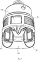
- the light 100 having a fly killing function illustrated herein comprises at least a LED chip 80, a fly storage means 70, a negative pressure fan 60, a fan hanger 40, a ventilation net 50, and a powers source.
- the LED chip 80 may be welded to a circuit board (not shown), such as an aluminum circuit board, and then the circuit board is secured to the lower end surface of the fly storage means 70.
- the LED chip 80 is coupled to the power source via the circuit board.
- the fly storage means 70 comprises an air inlet 730 and a fly storage groove 710 that is separated from the air inlet 730.
- the negative pressure fan 60 is mounted to the fan hanger 40 above the air inlet 730, and preferably, is extended a depth into the air inlet 730.
- a gap 65 that allows flies to pass therethrough is provided between the blades of the negative pressure fan 60 and the upper end of the fly storage means.
- the ventilation net 50 is provided with a plurality of ventilation holes 510 having a size capable of stopping flies from passing therethrough.
- the ventilation net is provided circumferentially between the outside wall 401 of the fan hanger 40 and the outside wall 701 of the fly storage means 70, with the fly storage means 70 being connected to the fan hanger 40.
- the fan hanger 40, the ventilation net 50 and the fly storage means 70 form a substantially closed space except the ventilation holes 510 and the air inlet 730.
- flies are photokinetic, once the LED chip is supplied with power and emits light, flies will aggregate around the LED chip 80, and sucked by the powered-on, rotating negative pressure fan 60 into the closed space except the ventilation holes 510 and the air inlet 730 formed by the fan hanger 40, the ventilation net 50 and the fly storage means 70 via the air inlet 730 of the fly storage means and the gap 65 formed between the blades of the negative pressure fan 60 and the upper end of the fly storage means 70. Due to the act of the negative pressure fan 60, the flies would not be able to fly backward out of the air inlet 730.
- the size of the ventilation holes 510 of the ventilation net 50 is capable of stopping the flies from passing therethrough, the flies would not be able to fly out of the closed space, and finally would fall within the fly storage groove 710 of the fly storage means, and air-dried to death.
- the LED chip 80 is a LED chip that is suitable for illumination and has strong attraction with respect to flies, and the selection of such a LED chip would be readily made by those skilled in the art.
- a plurality of LED chips are provided evenly on the lower ring shaped end surface of the fly storage means 70.
- the air inlet 730 is a passage running through the entire fly storage means 70.
- the air inlet is in the shape of a bell, i.e., the air inlet has an increasing cross section at the end approaching the negative pressure fan 60.
- the negative pressure fan 60 and the blades thereof are designed and installed in a way such that the blades extend a depth into the air inlet 730, and the shapes of the blades are fitted with the bell-shaped air inlet 730. This design can obtain a much stronger suction and facilitate trapping of flies in the fly storage means 70 via the air inlet 730 and the gap 65 formed between the blades of the negative pressure fan 60 and the upper end of the fly storage means 70.
- the ventilation net 50 is provided between the upper end of the side wall 701 of the fly storage means 70 and the lower end of the side wall 401 of the fan hanger 40. Particular ways of achieving this arrangement can be readily selected by those skilled in the art, and details for such particular ways will not be described herein for brevity.
- the ventilation net 50 is provided with a plurality of ventilation holes for discharging the air sucked by the negative pressure fan 60 out of the light having a fly killing function of the present invention.
- the ventilation holes 510 are preferably provided evenly in the entire ventilation net 50 so that the air can be discharged evenly, thereby reducing the noise.
- the size of the ventilation holes 510 should ensure that the flies trapped in the closed space would not be able to pass therethrough and escape.
- the ventilation holes 510 may be in the shape of a bell with the cross section thereof becoming increasingly larger from inside to outside, thereby further facilitating discharge of the air and reducing the noise of the air flow.
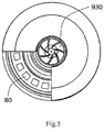
- the light 100 having a fly killing function of the present invention further comprises a transparent light cover 90 having a shape matching with the shape of the lower end of the fly storage means 70, and the transparent light cover 90 is secured to the lower end of the fly storage means 70.
- the transparent light cover 90 includes a light cover air inlet 930 that is in fluid communication with the air inlet 730 of the fly storage means 70.
- the transparent light cover 90 may be secured, such as by an adhesive, to the lower end of the fly storage means 70.
- the fly storage means 70 is connected with the fan hanger 40 by means of insertion, with the fan hanger including an insertion head 410 extending downward, and the fly storage means 70 including a socket 710 which engages with the insertion head 410.
- the fly storage means 70 may include an insertion head extending upward, and the fan hanger 40 includes a socket which engages with the insertion head.
- the insertion head may be provided with a screw hole (not shown), and a fastening screw can be used to fasten the insertion head and the socket together.
- the insertion head 410 is a portion of a cylinder having a thickness and a length
- the ventilation net 50 is installed abutting against the external side of the insertion head 410 and can rotate with respect to the same.
- the ventilation net 50 comprises a window opening 520 (see Fig. 4 ), which will be covered completely by the insertion head 40 when the light 100 having a fly killing function is in the working state, so as to form a closed space.
- the ventilation net 50 may be rotated so that the window opening 520 goes away from the insertion head 410 so that the interior of the light 100 having a fly killing function is viewable through the window opening 520, and if required, the flies trapped and air-dried in the fly storage groove 710 can be removed via the window opening 520.
- the insertion head 410 is provided with a through hole 410 for power lines (not shown) supplying power to the LED chips to pass through.
- a circuit board 30 for controlling the LED chips and the negative pressure fan may be further provided above the fan hanger 40.
- the circuit board 30 may be designed and manufactured as required, and the design and manufacture of the same are known, or at least readily achieved by those skilled in the art.
- the light 100 having a fly killing function of the present invention further comprises a circuit board cover 20.
- the circuit board cover 20, the circuit board 30 and the fan hanger 40 may be provided respectively with screw holes 210, 310 and 410 that a fastening screw (not shown) may be driven therethrough to fasten them together.
- the negative pressure fan 60 may be configured to be speed variable through the circuit board 30, such as a negative pressure fan speed adjusting rod 320 may be provided on the circuit board 30 and extends outside of the circuit board cover 20 from the circuit board 30 to facilitate manual adjustment of the speed of the negative pressure fan 60.
- a negative pressure fan speed adjusting rod 320 may be provided on the circuit board 30 and extends outside of the circuit board cover 20 from the circuit board 30 to facilitate manual adjustment of the speed of the negative pressure fan 60.
- a light head 10 is provided at the top of the circuit board cover shell 20.
- the light head 10 may comprise a male screw 110 on the outside wall thereof which can be rotated into a socket (not shown) for supplying power.
- a socket not shown
- the power lines 101 are coupled to the circuit board 30 so as to supply power thereto.
- Parts or components of the light having a fly killing function of the present invention may be formed of any suitable materials, such as for example, the circuit board, the fan hanger and the ventilation net may be formed of nylon, the negative pressure fan may be formed of polybutylene tertephehalate (PBT), and the fly storage means may be formed of an aluminum oxide ceramic.
- the present invention is not limited to such materials.
- the shape of the light having a fly killing function of the present invention is illustrated as generally cylindrical, it is not intended to be limited thereto.
- the light having fly killing function of the present invention may also be in the shape of an elliptic cylinder, a square column, or any other polygon column.
Landscapes
- Life Sciences & Earth Sciences (AREA)
- Engineering & Computer Science (AREA)
- Pest Control & Pesticides (AREA)
- General Engineering & Computer Science (AREA)
- Wood Science & Technology (AREA)
- Insects & Arthropods (AREA)
- Zoology (AREA)
- Environmental Sciences (AREA)
- Mechanical Engineering (AREA)
- Physics & Mathematics (AREA)
- Microelectronics & Electronic Packaging (AREA)
- Optics & Photonics (AREA)
- Catching Or Destruction (AREA)
- Apparatus For Disinfection Or Sterilisation (AREA)
- Disinfection, Sterilisation Or Deodorisation Of Air (AREA)
Applications Claiming Priority (2)
| Application Number | Priority Date | Filing Date | Title |
|---|---|---|---|
| CN201610952015.7A CN106342774B (zh) | 2016-11-03 | 2016-11-03 | 灭蚊虫灯 |
| PCT/CN2016/106908 WO2018082134A1 (fr) | 2016-11-03 | 2016-11-23 | Lampe pour tuer des moustiques |
Publications (3)
| Publication Number | Publication Date |
|---|---|
| EP3381280A1 true EP3381280A1 (fr) | 2018-10-03 |
| EP3381280A4 EP3381280A4 (fr) | 2019-06-12 |
| EP3381280B1 EP3381280B1 (fr) | 2022-01-05 |
Family
ID=57863867
Family Applications (1)
| Application Number | Title | Priority Date | Filing Date |
|---|---|---|---|
| EP16920625.7A Active EP3381280B1 (fr) | 2016-11-03 | 2016-11-23 | Lampe pour tuer des moustiques |
Country Status (5)
| Country | Link |
|---|---|
| US (1) | US10905111B2 (fr) |
| EP (1) | EP3381280B1 (fr) |
| CN (1) | CN106342774B (fr) |
| CA (1) | CA2952469C (fr) |
| WO (1) | WO2018082134A1 (fr) |
Families Citing this family (27)
| Publication number | Priority date | Publication date | Assignee | Title |
|---|---|---|---|---|
| USD770027S1 (en) * | 2015-06-30 | 2016-10-25 | Delta T Corporation | Fan |
| USD847969S1 (en) * | 2016-01-04 | 2019-05-07 | Delta T, Llc | Fan canopy |
| US10337675B2 (en) * | 2016-10-31 | 2019-07-02 | Clean Concept Llc | Insect control lighting device |
| US20210153493A1 (en) * | 2016-11-03 | 2021-05-27 | Jian Zhang | Light having a fly killing function |
| CN106342774B (zh) * | 2016-11-03 | 2022-04-22 | 张建 | 灭蚊虫灯 |
| US9968080B1 (en) * | 2017-02-17 | 2018-05-15 | Clean Concept Llc | Pest control lighting device |
| US11369104B2 (en) * | 2017-05-01 | 2022-06-28 | Pelsis Limited | Pest trap |
| CN206760542U (zh) * | 2017-05-24 | 2017-12-19 | 宁波大央工贸有限公司 | 灭蚊照明装置 |
| DE102017120212A1 (de) * | 2017-09-01 | 2019-03-07 | Biogents Ag | Insektenfalle und Verfahren zum Anlocken und/oder Fangen von Fluginsekten |
| CN207284942U (zh) * | 2017-10-18 | 2018-05-01 | 科林概念有限责任公司 | Led驱鼠灯 |
| CA2995537A1 (fr) * | 2018-02-16 | 2019-08-16 | Maxtech Mosquito Control Inc. | Ampoule intelligente |
| US11160265B2 (en) * | 2018-04-04 | 2021-11-02 | Philip Morris Usa Inc. | Insect trap utilizing UV light and method of use thereof |
| CN109673597A (zh) * | 2019-01-03 | 2019-04-26 | 福建网龙计算机网络信息技术有限公司 | 一种捕蚊器 |
| US11477976B2 (en) * | 2019-06-28 | 2022-10-25 | Epic Universal Technologies, Llc | Street light mosquito zapper |
| CN111406724A (zh) * | 2020-04-02 | 2020-07-14 | 常州市疾病预防控制中心 | 一种用于成蚊捕获装置及使用方法 |
| CN215602781U (zh) * | 2020-06-03 | 2022-01-25 | 北京必和易达知识产权咨询中心(有限合伙) | 一种昆虫杀灭装置 |
| US20220022441A1 (en) * | 2020-07-24 | 2022-01-27 | Ap&G Co., Inc. | Flying insect trap with enhanced illumination |
| CN214102884U (zh) * | 2020-12-02 | 2021-09-03 | 浙江硕而博科技股份有限公司 | 一种灭蚊灯 |
| US11864546B2 (en) | 2021-05-28 | 2024-01-09 | Florida Insect Control Group Llc | Multi-color insect light trap |
| US11751555B1 (en) | 2021-05-28 | 2023-09-12 | Florida Insect Control Group Llc | Multi-color insect light trap |
| CN217826450U (zh) * | 2022-03-21 | 2022-11-18 | 宁波大央科技有限公司 | 一种便携式灭蚊灯 |
| CN217609107U (zh) * | 2022-03-21 | 2022-10-21 | 宁波大央科技有限公司 | 一种灭蚊灯泡 |
| CN115380884B (zh) * | 2022-08-29 | 2024-09-27 | 山东省农业科学院 | 一种斑翅果蝇的诱集液智能释放检测装置 |
| CN117249426B (zh) * | 2023-10-23 | 2024-10-01 | 湖北工程学院 | 一种景观照明灯 |
| US12302886B1 (en) * | 2024-03-15 | 2025-05-20 | George Wesley Schaffer | Rotary insect trap |
| US12207641B1 (en) * | 2024-04-12 | 2025-01-28 | Xiaoling He | Bug zapper |
| CN119412675A (zh) * | 2025-01-06 | 2025-02-11 | 紫约农业科技集团有限公司 | 一种蓝莓大棚种植多色补光灯 |
Family Cites Families (48)
| Publication number | Priority date | Publication date | Assignee | Title |
|---|---|---|---|---|
| US1527976A (en) * | 1924-04-25 | 1925-03-03 | John G Haugart | Insect destroyer |
| US1962420A (en) * | 1932-12-22 | 1934-06-12 | William J Bradley | Electric insect exterminator |
| US2132371A (en) * | 1935-06-26 | 1938-10-04 | Kriwat Hans | Insect catcher with catching grid under electric tension |
| US2608022A (en) * | 1949-06-08 | 1952-08-26 | Evan H Wright | Insect destroyer |
| US2674682A (en) * | 1952-05-23 | 1954-04-06 | Bryan J Hanson | Electrically operated insect destroyer |
| US4951414A (en) * | 1988-05-09 | 1990-08-28 | U.S. Philips Corporation | Device for electrocuting insects |
| US4873786A (en) * | 1988-07-18 | 1989-10-17 | Franco Nicholas N | Bug whacker light |
| US20040159040A1 (en) * | 2003-02-13 | 2004-08-19 | Chen Chung Ming | Mosquito trap |
| US7036269B1 (en) * | 2004-10-14 | 2006-05-02 | Chang-Hao Chen | Multipurpose mosquito trap lamp |
| CN2757573Y (zh) * | 2004-12-31 | 2006-02-15 | 梁立人 | 旋涡吸风式灭蚊伞 |
| CN200997845Y (zh) * | 2006-11-08 | 2008-01-02 | 郭声光 | 一种捕蚊器 |
| US20080236028A1 (en) * | 2007-04-02 | 2008-10-02 | Mcbride William B | Flying insect trapping system |
| CN201119363Y (zh) * | 2007-11-14 | 2008-09-24 | 鹤山市晟泰精密模具有限公司 | 一种蚊蝇诱杀器 |
| USD583008S1 (en) * | 2008-06-09 | 2008-12-16 | Vranesh Peter R | Insect zapper |
| CN201230527Y (zh) | 2008-07-03 | 2009-05-06 | 邱景志 | 一种灭蚊器 |
| CN201270731Y (zh) | 2008-09-03 | 2009-07-15 | 马放 | 光催化灭蚊蝇器 |
| CN201444837U (zh) * | 2009-04-22 | 2010-05-05 | 郭声光 | 一种捕蚊器 |
| CN201585359U (zh) * | 2009-11-04 | 2010-09-22 | 漳州灿坤实业有限公司 | 一种捕蚊器 |
| US20140352200A1 (en) * | 2012-02-13 | 2014-12-04 | Craig Tremble | Insect Killing Apparatus and Method of Construction |
| KR101349733B1 (ko) * | 2012-06-13 | 2014-01-24 | 옥윤선 | 해충 포획장치 |
| CN203040489U (zh) * | 2013-01-24 | 2013-07-10 | 赵伟军 | 灭蚊灯 |
| CN203136859U (zh) | 2013-03-22 | 2013-08-21 | 环保之家生物科技股份有限公司 | 灭蚊器 |
| CN203457689U (zh) * | 2013-09-30 | 2014-03-05 | 张柳明 | 基于led灯光的蚊虫诱杀装置 |
| CN203505377U (zh) * | 2013-11-04 | 2014-04-02 | 张柳明 | 一种风扇可拆式灭蚊灯 |
| TWM480876U (zh) * | 2013-12-27 | 2014-07-01 | Shih Chuen Clocks Corp | 具風扇裝置之捕蚊結構 |
| CN103766310A (zh) * | 2014-02-19 | 2014-05-07 | 李起武 | 一种气流式灭蚊器 |
| KR20150125219A (ko) * | 2014-04-30 | 2015-11-09 | 서울바이오시스 주식회사 | 공기정화와 포충용 선풍기 |
| CN204153565U (zh) * | 2014-08-12 | 2015-02-11 | 徐梢芸 | 一种可驱蚊的野营灯 |
| CN204350918U (zh) * | 2014-11-10 | 2015-05-27 | 高雪艳 | 一种电器锁合保险结构及应用该结构的灭蚊器 |
| CN204393153U (zh) * | 2015-01-04 | 2015-06-17 | 中国科学院南京地理与湖泊研究所 | 一种能诱捕蚊蝇的小夜灯 |
| CN204466671U (zh) * | 2015-01-05 | 2015-07-15 | 北京净享科技有限公司 | 一种新型灭蚊灯 |
| CN204599088U (zh) * | 2015-01-23 | 2015-09-02 | 周泰 | 飞虫捕捉器 |
| CN204466683U (zh) * | 2015-02-09 | 2015-07-15 | 王梅 | 一种自动闭孔式照明电动捕虫器 |
| CN204682274U (zh) * | 2015-04-30 | 2015-10-07 | 宁波超顺电器有限公司 | 一种灭蚊灯 |
| CN205040481U (zh) * | 2015-09-15 | 2016-02-24 | 宁波大央工贸有限公司 | 灭蚊灯泡 |
| CN205266704U (zh) * | 2015-10-21 | 2016-06-01 | 宁波大央工贸有限公司 | 一种灭蚊灯 |
| CN105423151A (zh) * | 2015-12-13 | 2016-03-23 | 重庆桑耐美光电科技有限公司 | 多功能led照明灯 |
| CN105994215A (zh) * | 2016-06-20 | 2016-10-12 | 广东顺德斗禾电子科技有限公司 | 一种高效吸风灭蚊器 |
| US11064688B2 (en) * | 2016-06-27 | 2021-07-20 | Frank Billingsley, JR. | Electronic insect-control system |
| US20180035657A1 (en) * | 2016-08-02 | 2018-02-08 | Creative Pest Design Inc. | Pest control system |
| US10337675B2 (en) * | 2016-10-31 | 2019-07-02 | Clean Concept Llc | Insect control lighting device |
| CN106342774B (zh) * | 2016-11-03 | 2022-04-22 | 张建 | 灭蚊虫灯 |
| CN206213076U (zh) * | 2016-11-03 | 2017-06-06 | 张建 | 灭蚊虫灯 |
| US20180199563A1 (en) * | 2017-01-16 | 2018-07-19 | Jun Zheng | Mosquitocidal lamp with alarm function |
| US9968080B1 (en) * | 2017-02-17 | 2018-05-15 | Clean Concept Llc | Pest control lighting device |
| USD821537S1 (en) * | 2017-04-13 | 2018-06-26 | The New Genius (Sz) Technology Co., Limited | Mosquito zapper bulb |
| CN206760542U (zh) * | 2017-05-24 | 2017-12-19 | 宁波大央工贸有限公司 | 灭蚊照明装置 |
| US10701924B2 (en) * | 2017-11-28 | 2020-07-07 | Ningbo Dayang Industry And Trade Co., Ltd. | Mosquito-killing illuminating lamp |
-
2016
- 2016-11-03 CN CN201610952015.7A patent/CN106342774B/zh active Active
- 2016-11-23 WO PCT/CN2016/106908 patent/WO2018082134A1/fr not_active Ceased
- 2016-11-23 EP EP16920625.7A patent/EP3381280B1/fr active Active
- 2016-12-22 CA CA2952469A patent/CA2952469C/fr active Active
- 2016-12-28 US US15/392,306 patent/US10905111B2/en active Active
Also Published As
| Publication number | Publication date |
|---|---|
| CA2952469A1 (fr) | 2018-05-03 |
| US20180116195A1 (en) | 2018-05-03 |
| EP3381280B1 (fr) | 2022-01-05 |
| EP3381280A4 (fr) | 2019-06-12 |
| CN106342774A (zh) | 2017-01-25 |
| CN106342774B (zh) | 2022-04-22 |
| US10905111B2 (en) | 2021-02-02 |
| CA2952469C (fr) | 2018-09-18 |
| WO2018082134A1 (fr) | 2018-05-11 |
Similar Documents
| Publication | Publication Date | Title |
|---|---|---|
| EP3381280B1 (fr) | Lampe pour tuer des moustiques | |
| US20210153493A1 (en) | Light having a fly killing function | |
| ES2741436T3 (es) | Trampa para insectos que tiene un amortiguador accionado por aire | |
| KR102698511B1 (ko) | 포충기 | |
| KR101884528B1 (ko) | 모기 포획 장치 | |
| CN206760542U (zh) | 灭蚊照明装置 | |
| CN107182967B (zh) | 捕虫器 | |
| KR20180137876A (ko) | 동양하루살이를 포함한 해충 퇴치를 위한 포집장치 | |
| CN206835995U (zh) | 一种具有旋风罩的灭蚊灯 | |
| CN201418332Y (zh) | 一种捕蚊器 | |
| CN102669069A (zh) | 一种光气飞虫诱捕器 | |
| CN116146914A (zh) | 一种可捕捉飞虫的台灯 | |
| KR20160002012A (ko) | 해충 포획기 | |
| CN206213076U (zh) | 灭蚊虫灯 | |
| WO2011004782A1 (fr) | Dispositif d'éclairage permettant la capture d'insectes | |
| KR100986714B1 (ko) | 해충 퇴치용 팬 및 이를 이용한 해충퇴치기 | |
| CN210076389U (zh) | 一种多功能灭蚊灯 | |
| JP6358924B2 (ja) | 捕虫器 | |
| CN207962593U (zh) | 一种自动排除杂物的通风结构 | |
| KR100685009B1 (ko) | 해충 퇴치기 | |
| KR20210007230A (ko) | It기능이 구비된 포충장치 | |
| CN111197588A (zh) | 一种灭蚊风扇 | |
| CN208381821U (zh) | 一种灭蚊照明灯 | |
| JP2018108046A (ja) | 捕虫器 | |
| CN206641261U (zh) | 一种多功能灭蚊器 |
Legal Events
| Date | Code | Title | Description |
|---|---|---|---|
| STAA | Information on the status of an ep patent application or granted ep patent |
Free format text: STATUS: THE INTERNATIONAL PUBLICATION HAS BEEN MADE |
|
| PUAI | Public reference made under article 153(3) epc to a published international application that has entered the european phase |
Free format text: ORIGINAL CODE: 0009012 |
|
| STAA | Information on the status of an ep patent application or granted ep patent |
Free format text: STATUS: REQUEST FOR EXAMINATION WAS MADE |
|
| 17P | Request for examination filed |
Effective date: 20180629 |
|
| AK | Designated contracting states |
Kind code of ref document: A1 Designated state(s): AL AT BE BG CH CY CZ DE DK EE ES FI FR GB GR HR HU IE IS IT LI LT LU LV MC MK MT NL NO PL PT RO RS SE SI SK SM TR |
|
| AX | Request for extension of the european patent |
Extension state: BA ME |
|
| A4 | Supplementary search report drawn up and despatched |
Effective date: 20190513 |
|
| RIC1 | Information provided on ipc code assigned before grant |
Ipc: A01M 1/08 20060101AFI20190507BHEP |
|
| DAV | Request for validation of the european patent (deleted) | ||
| DAX | Request for extension of the european patent (deleted) | ||
| STAA | Information on the status of an ep patent application or granted ep patent |
Free format text: STATUS: EXAMINATION IS IN PROGRESS |
|
| 17Q | First examination report despatched |
Effective date: 20201209 |
|
| GRAP | Despatch of communication of intention to grant a patent |
Free format text: ORIGINAL CODE: EPIDOSNIGR1 |
|
| STAA | Information on the status of an ep patent application or granted ep patent |
Free format text: STATUS: GRANT OF PATENT IS INTENDED |
|
| INTG | Intention to grant announced |
Effective date: 20210630 |
|
| GRAS | Grant fee paid |
Free format text: ORIGINAL CODE: EPIDOSNIGR3 |
|
| GRAA | (expected) grant |
Free format text: ORIGINAL CODE: 0009210 |
|
| STAA | Information on the status of an ep patent application or granted ep patent |
Free format text: STATUS: THE PATENT HAS BEEN GRANTED |
|
| AK | Designated contracting states |
Kind code of ref document: B1 Designated state(s): AL AT BE BG CH CY CZ DE DK EE ES FI FR GB GR HR HU IE IS IT LI LT LU LV MC MK MT NL NO PL PT RO RS SE SI SK SM TR |
|
| REG | Reference to a national code |
Ref country code: GB Ref legal event code: FG4D |
|
| REG | Reference to a national code |
Ref country code: CH Ref legal event code: EP |
|
| REG | Reference to a national code |
Ref country code: AT Ref legal event code: REF Ref document number: 1459707 Country of ref document: AT Kind code of ref document: T Effective date: 20220115 |
|
| REG | Reference to a national code |
Ref country code: DE Ref legal event code: R096 Ref document number: 602016068231 Country of ref document: DE |
|
| REG | Reference to a national code |
Ref country code: IE Ref legal event code: FG4D |
|
| REG | Reference to a national code |
Ref country code: LT Ref legal event code: MG9D |
|
| REG | Reference to a national code |
Ref country code: NL Ref legal event code: MP Effective date: 20220105 |
|
| REG | Reference to a national code |
Ref country code: AT Ref legal event code: MK05 Ref document number: 1459707 Country of ref document: AT Kind code of ref document: T Effective date: 20220105 |
|
| PG25 | Lapsed in a contracting state [announced via postgrant information from national office to epo] |
Ref country code: NL Free format text: LAPSE BECAUSE OF FAILURE TO SUBMIT A TRANSLATION OF THE DESCRIPTION OR TO PAY THE FEE WITHIN THE PRESCRIBED TIME-LIMIT Effective date: 20220105 |
|
| PG25 | Lapsed in a contracting state [announced via postgrant information from national office to epo] |
Ref country code: SE Free format text: LAPSE BECAUSE OF FAILURE TO SUBMIT A TRANSLATION OF THE DESCRIPTION OR TO PAY THE FEE WITHIN THE PRESCRIBED TIME-LIMIT Effective date: 20220105 Ref country code: RS Free format text: LAPSE BECAUSE OF FAILURE TO SUBMIT A TRANSLATION OF THE DESCRIPTION OR TO PAY THE FEE WITHIN THE PRESCRIBED TIME-LIMIT Effective date: 20220105 Ref country code: PT Free format text: LAPSE BECAUSE OF FAILURE TO SUBMIT A TRANSLATION OF THE DESCRIPTION OR TO PAY THE FEE WITHIN THE PRESCRIBED TIME-LIMIT Effective date: 20220505 Ref country code: NO Free format text: LAPSE BECAUSE OF FAILURE TO SUBMIT A TRANSLATION OF THE DESCRIPTION OR TO PAY THE FEE WITHIN THE PRESCRIBED TIME-LIMIT Effective date: 20220405 Ref country code: LT Free format text: LAPSE BECAUSE OF FAILURE TO SUBMIT A TRANSLATION OF THE DESCRIPTION OR TO PAY THE FEE WITHIN THE PRESCRIBED TIME-LIMIT Effective date: 20220105 Ref country code: HR Free format text: LAPSE BECAUSE OF FAILURE TO SUBMIT A TRANSLATION OF THE DESCRIPTION OR TO PAY THE FEE WITHIN THE PRESCRIBED TIME-LIMIT Effective date: 20220105 Ref country code: ES Free format text: LAPSE BECAUSE OF FAILURE TO SUBMIT A TRANSLATION OF THE DESCRIPTION OR TO PAY THE FEE WITHIN THE PRESCRIBED TIME-LIMIT Effective date: 20220105 Ref country code: BG Free format text: LAPSE BECAUSE OF FAILURE TO SUBMIT A TRANSLATION OF THE DESCRIPTION OR TO PAY THE FEE WITHIN THE PRESCRIBED TIME-LIMIT Effective date: 20220405 |
|
| PG25 | Lapsed in a contracting state [announced via postgrant information from national office to epo] |
Ref country code: PL Free format text: LAPSE BECAUSE OF FAILURE TO SUBMIT A TRANSLATION OF THE DESCRIPTION OR TO PAY THE FEE WITHIN THE PRESCRIBED TIME-LIMIT Effective date: 20220105 Ref country code: LV Free format text: LAPSE BECAUSE OF FAILURE TO SUBMIT A TRANSLATION OF THE DESCRIPTION OR TO PAY THE FEE WITHIN THE PRESCRIBED TIME-LIMIT Effective date: 20220105 Ref country code: GR Free format text: LAPSE BECAUSE OF FAILURE TO SUBMIT A TRANSLATION OF THE DESCRIPTION OR TO PAY THE FEE WITHIN THE PRESCRIBED TIME-LIMIT Effective date: 20220406 Ref country code: FI Free format text: LAPSE BECAUSE OF FAILURE TO SUBMIT A TRANSLATION OF THE DESCRIPTION OR TO PAY THE FEE WITHIN THE PRESCRIBED TIME-LIMIT Effective date: 20220105 Ref country code: AT Free format text: LAPSE BECAUSE OF FAILURE TO SUBMIT A TRANSLATION OF THE DESCRIPTION OR TO PAY THE FEE WITHIN THE PRESCRIBED TIME-LIMIT Effective date: 20220105 |
|
| PG25 | Lapsed in a contracting state [announced via postgrant information from national office to epo] |
Ref country code: IS Free format text: LAPSE BECAUSE OF FAILURE TO SUBMIT A TRANSLATION OF THE DESCRIPTION OR TO PAY THE FEE WITHIN THE PRESCRIBED TIME-LIMIT Effective date: 20220505 |
|
| REG | Reference to a national code |
Ref country code: DE Ref legal event code: R097 Ref document number: 602016068231 Country of ref document: DE |
|
| PG25 | Lapsed in a contracting state [announced via postgrant information from national office to epo] |
Ref country code: SM Free format text: LAPSE BECAUSE OF FAILURE TO SUBMIT A TRANSLATION OF THE DESCRIPTION OR TO PAY THE FEE WITHIN THE PRESCRIBED TIME-LIMIT Effective date: 20220105 Ref country code: SK Free format text: LAPSE BECAUSE OF FAILURE TO SUBMIT A TRANSLATION OF THE DESCRIPTION OR TO PAY THE FEE WITHIN THE PRESCRIBED TIME-LIMIT Effective date: 20220105 Ref country code: RO Free format text: LAPSE BECAUSE OF FAILURE TO SUBMIT A TRANSLATION OF THE DESCRIPTION OR TO PAY THE FEE WITHIN THE PRESCRIBED TIME-LIMIT Effective date: 20220105 Ref country code: EE Free format text: LAPSE BECAUSE OF FAILURE TO SUBMIT A TRANSLATION OF THE DESCRIPTION OR TO PAY THE FEE WITHIN THE PRESCRIBED TIME-LIMIT Effective date: 20220105 Ref country code: DK Free format text: LAPSE BECAUSE OF FAILURE TO SUBMIT A TRANSLATION OF THE DESCRIPTION OR TO PAY THE FEE WITHIN THE PRESCRIBED TIME-LIMIT Effective date: 20220105 Ref country code: CZ Free format text: LAPSE BECAUSE OF FAILURE TO SUBMIT A TRANSLATION OF THE DESCRIPTION OR TO PAY THE FEE WITHIN THE PRESCRIBED TIME-LIMIT Effective date: 20220105 |
|
| PLBE | No opposition filed within time limit |
Free format text: ORIGINAL CODE: 0009261 |
|
| STAA | Information on the status of an ep patent application or granted ep patent |
Free format text: STATUS: NO OPPOSITION FILED WITHIN TIME LIMIT |
|
| PG25 | Lapsed in a contracting state [announced via postgrant information from national office to epo] |
Ref country code: AL Free format text: LAPSE BECAUSE OF FAILURE TO SUBMIT A TRANSLATION OF THE DESCRIPTION OR TO PAY THE FEE WITHIN THE PRESCRIBED TIME-LIMIT Effective date: 20220105 |
|
| 26N | No opposition filed |
Effective date: 20221006 |
|
| PG25 | Lapsed in a contracting state [announced via postgrant information from national office to epo] |
Ref country code: SI Free format text: LAPSE BECAUSE OF FAILURE TO SUBMIT A TRANSLATION OF THE DESCRIPTION OR TO PAY THE FEE WITHIN THE PRESCRIBED TIME-LIMIT Effective date: 20220105 |
|
| PG25 | Lapsed in a contracting state [announced via postgrant information from national office to epo] |
Ref country code: MC Free format text: LAPSE BECAUSE OF FAILURE TO SUBMIT A TRANSLATION OF THE DESCRIPTION OR TO PAY THE FEE WITHIN THE PRESCRIBED TIME-LIMIT Effective date: 20220105 |
|
| REG | Reference to a national code |
Ref country code: CH Ref legal event code: PL |
|
| REG | Reference to a national code |
Ref country code: BE Ref legal event code: MM Effective date: 20221130 |
|
| PG25 | Lapsed in a contracting state [announced via postgrant information from national office to epo] |
Ref country code: LI Free format text: LAPSE BECAUSE OF NON-PAYMENT OF DUE FEES Effective date: 20221130 Ref country code: IT Free format text: LAPSE BECAUSE OF FAILURE TO SUBMIT A TRANSLATION OF THE DESCRIPTION OR TO PAY THE FEE WITHIN THE PRESCRIBED TIME-LIMIT Effective date: 20220105 Ref country code: CH Free format text: LAPSE BECAUSE OF NON-PAYMENT OF DUE FEES Effective date: 20221130 |
|
| PG25 | Lapsed in a contracting state [announced via postgrant information from national office to epo] |
Ref country code: LU Free format text: LAPSE BECAUSE OF NON-PAYMENT OF DUE FEES Effective date: 20221123 |
|
| PG25 | Lapsed in a contracting state [announced via postgrant information from national office to epo] |
Ref country code: IE Free format text: LAPSE BECAUSE OF NON-PAYMENT OF DUE FEES Effective date: 20221123 |
|
| PG25 | Lapsed in a contracting state [announced via postgrant information from national office to epo] |
Ref country code: BE Free format text: LAPSE BECAUSE OF NON-PAYMENT OF DUE FEES Effective date: 20221130 |
|
| PG25 | Lapsed in a contracting state [announced via postgrant information from national office to epo] |
Ref country code: HU Free format text: LAPSE BECAUSE OF FAILURE TO SUBMIT A TRANSLATION OF THE DESCRIPTION OR TO PAY THE FEE WITHIN THE PRESCRIBED TIME-LIMIT; INVALID AB INITIO Effective date: 20161123 |
|
| PG25 | Lapsed in a contracting state [announced via postgrant information from national office to epo] |
Ref country code: CY Free format text: LAPSE BECAUSE OF FAILURE TO SUBMIT A TRANSLATION OF THE DESCRIPTION OR TO PAY THE FEE WITHIN THE PRESCRIBED TIME-LIMIT Effective date: 20220105 |
|
| PG25 | Lapsed in a contracting state [announced via postgrant information from national office to epo] |
Ref country code: MK Free format text: LAPSE BECAUSE OF FAILURE TO SUBMIT A TRANSLATION OF THE DESCRIPTION OR TO PAY THE FEE WITHIN THE PRESCRIBED TIME-LIMIT Effective date: 20220105 |
|
| PG25 | Lapsed in a contracting state [announced via postgrant information from national office to epo] |
Ref country code: TR Free format text: LAPSE BECAUSE OF FAILURE TO SUBMIT A TRANSLATION OF THE DESCRIPTION OR TO PAY THE FEE WITHIN THE PRESCRIBED TIME-LIMIT Effective date: 20220105 |
|
| PG25 | Lapsed in a contracting state [announced via postgrant information from national office to epo] |
Ref country code: MT Free format text: LAPSE BECAUSE OF FAILURE TO SUBMIT A TRANSLATION OF THE DESCRIPTION OR TO PAY THE FEE WITHIN THE PRESCRIBED TIME-LIMIT Effective date: 20220105 |
|
| PGFP | Annual fee paid to national office [announced via postgrant information from national office to epo] |
Ref country code: GB Payment date: 20250925 Year of fee payment: 10 |
|
| PGFP | Annual fee paid to national office [announced via postgrant information from national office to epo] |
Ref country code: FR Payment date: 20250925 Year of fee payment: 10 |
|
| PGFP | Annual fee paid to national office [announced via postgrant information from national office to epo] |
Ref country code: DE Payment date: 20250925 Year of fee payment: 10 |