EP3389135B1 - Elektromagnetische nahfeld-induktionsantenne (nfem) - Google Patents
Elektromagnetische nahfeld-induktionsantenne (nfem) Download PDFInfo
- Publication number
- EP3389135B1 EP3389135B1 EP18162215.0A EP18162215A EP3389135B1 EP 3389135 B1 EP3389135 B1 EP 3389135B1 EP 18162215 A EP18162215 A EP 18162215A EP 3389135 B1 EP3389135 B1 EP 3389135B1
- Authority
- EP
- European Patent Office
- Prior art keywords
- coil
- antenna
- coils
- coupled
- coupling coefficient
- Prior art date
- Legal status (The legal status is an assumption and is not a legal conclusion. Google has not performed a legal analysis and makes no representation as to the accuracy of the status listed.)
- Active
Links
Images


Classifications
-
- H—ELECTRICITY
- H04—ELECTRIC COMMUNICATION TECHNIQUE
- H04B—TRANSMISSION
- H04B5/00—Near-field transmission systems, e.g. inductive or capacitive transmission systems
- H04B5/20—Near-field transmission systems, e.g. inductive or capacitive transmission systems characterised by the transmission technique; characterised by the transmission medium
- H04B5/24—Inductive coupling
- H04B5/26—Inductive coupling using coils
-
- H—ELECTRICITY
- H01—ELECTRIC ELEMENTS
- H01Q—ANTENNAS, i.e. RADIO AERIALS
- H01Q7/00—Loop antennas with a substantially uniform current distribution around the loop and having a directional radiation pattern in a plane perpendicular to the plane of the loop
-
- H—ELECTRICITY
- H01—ELECTRIC ELEMENTS
- H01Q—ANTENNAS, i.e. RADIO AERIALS
- H01Q1/00—Details of, or arrangements associated with, antennas
- H01Q1/27—Adaptation for use in or on movable bodies
- H01Q1/273—Adaptation for carrying or wearing by persons or animals
-
- H—ELECTRICITY
- H01—ELECTRIC ELEMENTS
- H01Q—ANTENNAS, i.e. RADIO AERIALS
- H01Q1/00—Details of, or arrangements associated with, antennas
- H01Q1/36—Structural form of radiating elements, e.g. cone, spiral, umbrella; Particular materials used therewith
-
- H—ELECTRICITY
- H01—ELECTRIC ELEMENTS
- H01Q—ANTENNAS, i.e. RADIO AERIALS
- H01Q1/00—Details of, or arrangements associated with, antennas
- H01Q1/50—Structural association of antennas with earthing switches, lead-in devices or lightning protectors
-
- H—ELECTRICITY
- H01—ELECTRIC ELEMENTS
- H01Q—ANTENNAS, i.e. RADIO AERIALS
- H01Q21/00—Antenna arrays or systems
- H01Q21/0006—Particular feeding systems
-
- H—ELECTRICITY
- H01—ELECTRIC ELEMENTS
- H01Q—ANTENNAS, i.e. RADIO AERIALS
- H01Q7/00—Loop antennas with a substantially uniform current distribution around the loop and having a directional radiation pattern in a plane perpendicular to the plane of the loop
- H01Q7/06—Loop antennas with a substantially uniform current distribution around the loop and having a directional radiation pattern in a plane perpendicular to the plane of the loop with core of ferromagnetic material
- H01Q7/08—Ferrite rod or like elongated core
-
- H—ELECTRICITY
- H04—ELECTRIC COMMUNICATION TECHNIQUE
- H04B—TRANSMISSION
- H04B5/00—Near-field transmission systems, e.g. inductive or capacitive transmission systems
- H04B5/20—Near-field transmission systems, e.g. inductive or capacitive transmission systems characterised by the transmission technique; characterised by the transmission medium
- H04B5/22—Capacitive coupling
-
- H—ELECTRICITY
- H04—ELECTRIC COMMUNICATION TECHNIQUE
- H04B—TRANSMISSION
- H04B5/00—Near-field transmission systems, e.g. inductive or capacitive transmission systems
- H04B5/20—Near-field transmission systems, e.g. inductive or capacitive transmission systems characterised by the transmission technique; characterised by the transmission medium
- H04B5/24—Inductive coupling
- H04B5/26—Inductive coupling using coils
- H04B5/263—Multiple coils at either side
-
- H—ELECTRICITY
- H04—ELECTRIC COMMUNICATION TECHNIQUE
- H04B—TRANSMISSION
- H04B5/00—Near-field transmission systems, e.g. inductive or capacitive transmission systems
- H04B5/40—Near-field transmission systems, e.g. inductive or capacitive transmission systems characterised by components specially adapted for near-field transmission
- H04B5/43—Antennas
-
- H—ELECTRICITY
- H04—ELECTRIC COMMUNICATION TECHNIQUE
- H04B—TRANSMISSION
- H04B1/00—Details of transmission systems, not covered by a single one of groups H04B3/00 - H04B13/00; Details of transmission systems not characterised by the medium used for transmission
- H04B1/38—Transceivers, i.e. devices in which transmitter and receiver form a structural unit and in which at least one part is used for functions of transmitting and receiving
- H04B1/3827—Portable transceivers
- H04B1/385—Transceivers carried on the body, e.g. in helmets
Definitions
- the present specification relates to systems, methods, apparatuses, devices, articles of manufacture and instructions an NFEMI antenna.
- EP 3 136 614 A1 describes a near-field electromagnetic induction antenna including: an electric antenna including a plate; a first feeding connection and a second feeding connection; and a magnetic antenna including a first coil and a second coil, wherein the first coil and the second coil are mutually coupled, wherein a first connection of the first coil is connected to the first feeding connection, wherein a second connection of the first coil and a first connection of the second coil is connected to the second feeding connection, and wherein a second connection of the second coil is connected to the plate.
- a near-field electromagnetic induction (NFEMI) antenna comprising: an electric antenna including a first electrically conductive surface and a second electrically conductive surface; a magnetic antenna including a first coil, a second coil and a third coil; a first feeding connection coupled to one end of the first coil and the first electrically conductive surface; a second feeding connection coupled to another end of the first coil and coupled to one end of the second coil; wherein another end of the second coil is coupled to one end of the third coil; wherein another end of the third coil is coupled to the second electrically conductive surface; wherein the first, second and third coils are configured to carry a time varying current from the first and second feeding connections in a same direction; wherein the first coil is configured to have a first coupling coefficient with the second coil; and wherein the first coil is configured to have a second coupling coefficient with the third coil.
- the first and second coils are configured as a bifilar wound set of wires; and the third coil is not configured as part of the bifilar
- Example embodiments of a near-field electromagnetic induction (NFEMI) communication system can operate near a human body by means of a combination of a magnetic field and electric field without the use of transversal radiating waves.
- NFEMI systems improve a wearable device's signal link budget and extend their range to a complete human body.
- NFEMI communication utilizes non-propagating quasi-static fields.
- the quasi-static characteristic of the fields is the result of antenna dimensions in combination with the carrier frequency. The majority of the energy is stored in the form of magnetic and electric fields and a small amount of RF energy inevitably propagates in free space.
- Such an antenna can be a coil antenna that allows near field magnetic induction (NFMI).
- Other antennas communicate by means of both magnetic and electric near fields via near field electromagnetic induction (NFEMI).
- NFEMI near field electromagnetic induction
- Figure 1A is an example structural diagram of a first NFEMI antenna 600.
- the antenna system 600 is a combination of an electrical antenna 620 and a magnetic antenna 605.
- the magnetic antenna 605 includes two coupled coils 615 and 617.
- the first coil 615 has an inductance of L1
- the second coil 617 has an inductance of L2. Both coils 615 and 617 may be connected such that they form a larger inductance compared with the sum of the inductance of the first coil 615 and the second coil 617.
- Both coils 615 and 617 may be air coils, form a planar structure, can be wrapped around a ferrite or non-ferrite core 612, or can be wrapped around a magnetic permeable material 610 (e.g. a planar sheet, a ferrite shield, a ferrite sheet or a coating comprising ferrite particles in suspension) which is then wrapped around the core 612.
- the coils 615 and 617 are wrapped around the core 612 in an interleaved fashion.
- the coils 615 and 617 are wrapped on top of one another. In this way, the second coil 617 is first wrapped around the magnetic permeable material 610 and the core 612, and then the first coil 615 is wrapped around the second coil 617, the magnetic permeable material 610 and the core 612.
- a first connection of the first coil 615 is connected to a first feeding connection 637.
- the second connection of the first coil 615 is connected to a first connection of the second coil 617 and to a second feeding connection 635.
- a second connection of the second coil 617 is connected to an electrically conductive surface 630 within the electric antenna 620.
- the antenna 600 will provide fields that are confined near the body.
- the preferred transmit frequency is below 30MHz to ensure that the fields are following the body contours and far field radiation is strongly reduced.
- the electrically conductive surface 630 can be wrapped completely, partially or multiply around the coils 615 and 617, any magnetic permeable material 610 and the core 612.
- the phrase "wrapped around” is herein defined to include encircling an object (e.g. core 612) either completely (e.g. by at least 360 angular degrees), partially (e.g. by less than 360 angular degrees) or multiply (e.g. by more than 360 angular degrees, such as several turns of the coils 615 and 617 about the core 612).
- "wrapped around” may only cover, for example, 10 angular degrees about an object such as the core 612.
- the core 612 may be of any shape or size.
- the core 612 may also be at least one of: a non-magnetic metallic core, a battery (e.g. a coin cell battery), or a solid.
- the core 612 may include various circuitry (e.g. the electrical apparatus referred to herein), and/or other electrical and mechanical parts that may or may not be necessary for functioning of the electrical apparatus or the NFEMI antenna 600.
- the feeding connections 637 and 635 are connected to an electrical apparatus (not shown).
- the electrical apparatus embodiments can include: an integrated circuit (IC), an RF IC, a connector port, or other circuit elements.
- the circuit elements in the electrical apparatus can include: a tuning circuit having capacitive and resistive tuning banks, a receiver circuit and/or a transmitter circuit.
- the electrical apparatus may also include: radio functionality, a microprocessor, a digital signal processor, an audio amplifier, a data processing unit, a human interface unit, and/or another antenna.
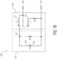
- Figure 1B is an example equivalent electrical circuit 601 for the first NFEMI antenna 600 configured to be connected to an electrical apparatus (not shown).
- the electrical antenna 620 e.g. short loaded dipole
- the resistance R1 represents the loss of a medium that separates the plates 625 and 630.
- the plates 625 and 630 are separate from the coils 615 and 617, while in another example embodiment at least one of the coils 615 and 617 also functions as at least one of the electrical antenna 620 capacitive plates 625.
- the magnetic antenna 605 (e.g. small loop antenna) is electrically represented by at least the two coupled coils 615, 617 of which the first coil 615 has an inductance of L1, and the second coil 617 has an inductance of L2.
- the resistance R2 represents the loss of the coupled coils.
- the second NFEMI antenna provides an increased magnetic field strength and an increased electric field strength in transmit mode.
- the received voltage in receive mode is also increased.
- the second NFEMI antenna's structure can be integrated into very small wireless portable products near to the human body like a smart planar patch, body network devices for healthcare applications, earbuds, hearing aids, and others.
- FIG. 2A is an example equivalent electrical circuit for a second NFEMI antenna 200 configured to be connected to an electrical apparatus (not shown).
- the second NFEMI antenna 200 includes: an electrical antenna 202, a magnetic antenna 204, a first feeding connection 206 (F1), and a second feeding connection 208 (F2).
- the antenna 200 is coupled to a substrate (not shown) (e.g. planar sheet, core, etc.) or a core (not shown).
- the antenna 200 is coupled to an electrical apparatus (not shown) (e.g. a wireless device, a body network, an integrated circuit (IC), an RF IC, a connector port, a circuit element; a tuning circuit, a receiver circuit and/or a transmitter circuit, a radio circuit, a microprocessor, a digital signal processor, an audio amplifier, a data processing unit, a human interface unit, and/or another antenna).
- an electrical apparatus e.g. a wireless device, a body network, an integrated circuit (IC), an RF IC, a connector port, a circuit element; a tuning circuit, a receiver circuit and/or a transmitter circuit, a radio circuit, a microprocessor, a digital signal processor, an audio amplifier, a data processing unit, a human interface unit, and/or another antenna).
- the electrical antenna 202 includes a first electrically conductive surface 210 (S1) and a second electrically conductive surface 212 (S2).
- the magnetic antenna 204 includes a first coil 214 (L1), a second coil 216 (L2), and a third coil 218 (L3).
- a first coupling coefficient (K1) is defined between the first coil 214 (L1) and the second coil 216 (L2).
- a second coupling coefficient (K2) is defined between the first coil 214 (L1) and the third coil 218 (L3).
- the first feeding connection 206 is coupled to one end 226 of the first coil 214 and the first electrically conductive surface 210.
- the second feeding connection 208 is coupled to another end 224 of the first coil 214 and coupled to one end 224 of the second coil 216.
- Another end 222 of the second coil 216 is coupled to one end 222 of the third coil 218.
- Another end 220 of the third coil 218 is coupled to the second electrically conductive surface 212.
- the first coil 214 (L1), the second coil 216 (L2) and third coil 218 (L3) are each configured to carry a time varying current from the first and second feeding connections in a same direction. See Figure 2B for an example instantaneous current direction ( ⁇ ) in the antenna 200.
- the first feeding connection 206 (F1) and second feeding connection 208 (F2) are in some example embodiments connected to an electrical apparatus (not shown) (e.g. transceiver, radio system, etc.).
- an electrical apparatus e.g. transceiver, radio system, etc.
- the electric antenna 202 is formed by the first electrically conductive surface 210 (S1) and the second electrically conductive surface 212 (S2) and includes a parasitic resistance R1.
- the surfaces 210, 212 (S1, S2) are separated and form capacitor Ca at a communication frequency of the antenna 200.
- the separation between the two surfaces 210, 212 (S1, S2) in some embodiments is very small compared with a wavelength of the antenna's 200 communication frequency.
- surfaces 210, 212 (S1, S2) may have a separation on the order of 4 mm, compared with the antenna's 200 communication frequency wavelength of 30 meters.
- the electric antenna's 202 surfaces 210, 212 can be placed on either side of a substrate (not shown).
- the substrate material can be either, or a combination of: a patch, a medical patch, air, a high dielectric material, or a polyethylene foam.
- R1 represents the loss of a substrate material to which the surfaces 210, 212 are attached.
- the electric antenna 202 may be formed by combining the first electrically conductive surface 210 (S1) with the second electrically conductive surface 212 (S2) formed from one or more of the magnetic antenna 204 coils 214, 216, 218 (L1, L2, L3).
- the magnetic antenna 204 is formed by the three planar coils 214, 216, 218 (L1, L2, L3) each having spiral shape.
- the coils 214, 216, 218 (L1, L2, L3) are not completely planar but follow a shape determined by the wireless product in which they are used.
- the coils 214, 216, 218 (L1, L2, L3) includes a parasitic resistance R2.
- the resistor R2 represents the loss of the coupled coils 214, 216, 218 (L1, L2, L3).
- the coils 214, 216, 218 (L1, L2, L3) are configured to be magnetically coupled to each other during operation and are connected in series with each other and each have a same winding direction.
- the first coil 214 is configured to have a first coupling coefficient (K1) with the second coil 216, and the first coil 214 is configured to have a second coupling coefficient (K2) with the third coil 218.
- the first coil 214 (L1) and the second coil 216 (L2) are physically positioned to create the first coupling coefficient (K1).
- the third coil 218 (L3) is physically positioned with respect to the first coil 214 to create the second coupling coefficient (K2).
- a ratio between the first and second coupling coefficients is such that: 0 ⁇ K2/K1 ⁇ 1.
- the exact coupling coefficient ratio will vary depending upon the antenna's 200 application (e.g. receiver only, transmitter only, combination receiver-transmitter, etc.).
- the coupling coefficient between the first coil 214 (L1) and the second coil 216 (L2) i.e. K1 is 0.5 ⁇ K1 ⁇ .95
- the coupling coefficient between L1 and L3 (K2) is 0.1 ⁇ K2 ⁇ 0.5.
- the antenna 200 includes a bifilar portion 228 and a non-bifilar portion 230.
- the bifilar portion 228 includes the first coil 214 (L1) and the second coil 216 (L2) wound like a bifilar coil to create the first coupling coefficient (K1).
- Bifilar winding is a method where a set of wires are wound besides each other. This leads to a relative high coupling coefficient between the first and second coils 214, 216 (L1, L2).
- the non-bifilar portion 230 includes the third coil 218 (L3) which is not bifilar wound with the first and second coils 214, 216 and/or is also kept distant from either or both the first or second coils 214, 216 so as to create the second coupling coefficient (K2), which is weaker (i.e. smaller) than the first coupling coefficient (K1).
- a signal from a transmitter source coupled to the first and second feeding connections is amplified and over unity on the capacitor Ca.
- a planar set of coils 214, 216, 218 L1, L2, L3
- L1 7 turns
- L2 7 turns
- L3 10 turns (more L3 turns since diameter of turns is smaller (i.e. it's in the center of L1 & L2 coils))
- a surface area of 22x22 mm when Ca is 10 pF, and the Ca impedance at 10 MHz is 1.5 kohms, a voltage gain of 2.56 has been measured.
- a parasitic capacitance between the first coil 214 (L1) and the second coil 216 (L2) needs to be reduced such that the parasitic capacitance does not reduce V2 between the first electrically conductive surface 210 (S1) and the second electrically conductive surface 212 (S2) and thus interfere with the electrical antenna 202 signals.
- One way to reduce the parasitic capacitance is to place the first coil 214 (L1) and the second coil 216 (L2) on either side of a substrate (not shown).
- the coils 214, 216, 218 can be wrapped around an object (e.g. a core) and have a variety of shapes (e.g. circular, square, etc.).
- the radio system may contain a variable capacitor to resonate the second NFEMI antenna 200 at a communication frequency (e.g. below 30 MHz and/or about 10.6 MHz).
- the radio systems may also contain a variable resistor to define the bandwidth of the antenna suitable for the modulated communication signal.
- the electrical apparatus in a receive mode the feeding connections 206, 208 and a tuning system may be further connected to a low noise amplifier, LNA, and other baseband functions.
- LNA low noise amplifier
- the feeding connections 206, 208 are connected to a modulated signal source.
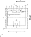
- Figure 2B is an example structural diagram of the second NFEMI antenna 200.
- the third coil 218 (L3) is wound on a planar substrate inside of the first coil 214 (L1) and the second coil 216 (L2).
- the third coil 218 (L3) could be placed on the planar surface on outside of the first coil 214 (L1) and the second coil 216 (L2).
- the antenna 200 discussed above improves reliability for wireless communications in applications such as consumer lifestyle and healthcare.
- the antenna 200 provides an improved communication link, at least in part by generating stronger electrical and magnetic fields in a wireless transmit mode and a higher voltage in a wireless receive mode.
- the patch can be configured to be attached to a surface of a living entity (e.g. the human body) for effecting functions such as, monitoring a person's vital signs, or for dispensing medicine or other therapies.
- a living entity e.g. the human body
- Example near-field electromagnetic induction (NFEMI) antenna including: an electric antenna having a first surface and a second surface; a magnetic antenna having a first, second and third coils; a first feeding connection coupled to one end of the first coil and the first surface; a second feeding connection coupled to another end of the first coil and coupled to one end of the second coil; wherein another end of the second coil is coupled to one end of the third coil; wherein another end of the third coil is coupled to the second surface; wherein the first, second and third coils are configured to carry a time varying current from the first and second feeding connections in a same direction; wherein the first and second coils are configured to have a first coupling coefficient; and wherein the first and third coils are configured to have a second coupling coefficient.
- NFEMI near-field electromagnetic induction
Landscapes
- Engineering & Computer Science (AREA)
- Computer Networks & Wireless Communication (AREA)
- Signal Processing (AREA)
- Details Of Aerials (AREA)
- Near-Field Transmission Systems (AREA)
Claims (14)
- Eine Nahfeld elektromagnetische Induktion, NFEMI, Antenne (200), aufweisend:eine elektrische Antenne, die eine erste elektrisch leitende Oberfläche (210) und eine zweite elektrisch leitende Oberfläche (212) beinhaltet;eine magnetische Antenne, die eine erste Spule (214), eine zweite Spule (216) und eine dritte Spule (218) beinhaltet;eine erste Einspeiseverbindung (206), die mit einem Ende der ersten Spule (214) und der ersten elektrisch leitenden Oberfläche (210) gekoppelt ist;eine zweite Einspeiseverbindung (208), die mit einem anderen Ende der ersten Spule (214) gekoppelt ist und mit einem Ende der zweiten Spule (216) gekoppelt ist;wobei ein anderes Ende (222) der zweiten Spule (216) mit einem Ende der dritten Spule (218) gekoppelt ist;wobei ein anderes Ende der dritten Spule mit der zweiten elektrisch leitenden Oberfläche (212) gekoppelt ist;wobei die erste, die zweite und die dritte Spule (214, 216, 218) konfiguriert sind, einen zeitveränderlichen Strom von der ersten und der zweiten Einspeiseverbindung (206, 208) in eine gleiche Richtung zu übertragen;wobei die erste Spule (214) konfiguriert ist, einen ersten Kopplungskoeffizienten (K1) mit der zweiten Spule (216) zu haben; undwobei die erste Spule (214) konfiguriert ist, einen zweiten Kopplungskoeffizienten (K2) mit der dritten Spule (218) zu haben,dadurch gekennzeichnet, dassdie erste und die zweite Spule als ein bifilar gewickelter Satz von Drähten (228) konfiguriert sind; unddie dritte Spule (218) nicht als Teil des bifilar gewickelten Satzes von Drähten konfiguriert ist (228).
- Die Antenne (200) gemäß Anspruch 1:
wobei jede der Spulen (214, 216, 218) in Reihe gekoppelt ist. - Die Antenne (200) gemäß einem vorhergehenden Anspruch:
wobei jede der Spulen (214, 216, 218) eine gleiche Wicklungsrichtung hat. - Die Antenne (200) gemäß einem vorhergehenden Anspruch:
wobei der erste Kopplungskoeffizient (K1) größer als der zweite Kopplungskoeffizient (K2) ist. - Die Antenne (200) gemäß einem vorhergehenden Anspruch:
wobei ein Verhältnis, das durch Teilung des zweiten Kopplungskoeffizienten (K2) durch den ersten Kopplungskoeffizienten (K1) gebildet wird, zwischen 0 und 1 ist. - Die Antenne (200) gemäß einem vorhergehenden Anspruch:wobei die erste und die zweite Spule (214, 216) als ein Satz paralleler Drähte, die durch einen ersten Abstand getrennt sind, physikalisch positioniert sind;wobei die dritte Spule (218) von dem Satz paralleler Drähte durch einen zweiten Abstand getrennt ist; undwobei der zweite Abstand größer als der erste Abstand ist.
- Die Antenne (200) gemäß einem vorhergehenden Anspruch:
wobei mindestens eine der Spulen in einer Form ausgebildet ist, die beinhaltet: einen Kreis, ein Quadrat, ein Oval oder eine Raute. - Die Antenne (200) gemäß einem vorhergehenden Anspruch:
wobei die dritte Spule (218) innerhalb eines Umfangs lokalisiert ist, der durch die erste und die zweite Spule (214, 216) gebildet wird. - Die Antenne (200) gemäß einem vorhergehenden Anspruch:
wobei die dritte Spule (218) außerhalb eines Umfangs lokalisiert ist, der durch die erste und die zweite Spule (214, 216) gebildet wird. - Die Antenne (200) gemäß einem vorhergehenden Anspruch:ferner aufweisend ein planes Substrat;wobei die erste Spule (214) auf einer Seite des Substrats ist und die zweite und die dritte Spule (216, 218) auf einer anderen Seite des Substrats sind.
- Die Antenne (200) gemäß einem vorhergehenden Anspruch:
wobei die erste, die zweite und die dritte Spule (214, 216, 218) und die erste und die zweite elektrisch leitende Oberfläche (210, 212) auf dem Substrat ausgebildet sind. - Die Antenne (200) gemäß einem vorhergehenden Anspruch:
wobei das Substrat mindestens eines beinhaltet von: einem Pflaster, einem medizinischen Pflaster, Luft, einem hochdielektrischen Material und einem Polyethylenschaum. - Die Antenne (200) gemäß einem der Ansprüche 1 bis 12:wobei die Antenne in ein medizinisches Pflaster eingebettet ist, das konfiguriert ist, an einer Oberfläche einer lebenden Entität befestigt zu werden; undwobei das Pflaster einen Teil des Substrats bildet.
- Die Antenne (200) gemäß einem vorhergehenden Anspruch:
wobei die erste, die zweite und die dritte Spule (214, 216, 218) und die erste und die zweite elektrisch leitende Oberfläche (210, 212) um einen Kern gewickelt sind.
Applications Claiming Priority (1)
| Application Number | Priority Date | Filing Date | Title |
|---|---|---|---|
| US15/482,895 US9941937B1 (en) | 2017-04-10 | 2017-04-10 | Near-field electromagnetic induction (NFEMI) antenna |
Publications (2)
| Publication Number | Publication Date |
|---|---|
| EP3389135A1 EP3389135A1 (de) | 2018-10-17 |
| EP3389135B1 true EP3389135B1 (de) | 2020-05-20 |
Family
ID=61691313
Family Applications (1)
| Application Number | Title | Priority Date | Filing Date |
|---|---|---|---|
| EP18162215.0A Active EP3389135B1 (de) | 2017-04-10 | 2018-03-16 | Elektromagnetische nahfeld-induktionsantenne (nfem) |
Country Status (3)
| Country | Link |
|---|---|
| US (1) | US9941937B1 (de) |
| EP (1) | EP3389135B1 (de) |
| CN (1) | CN108695593B (de) |
Families Citing this family (6)
| Publication number | Priority date | Publication date | Assignee | Title |
|---|---|---|---|---|
| US10615502B2 (en) * | 2018-06-29 | 2020-04-07 | Nxp B.V. | Near-field electromagnetic induction (NFEMI) antenna |
| US11368193B2 (en) * | 2020-02-04 | 2022-06-21 | Nxp B.V. | Near-field electromagnetic induction (NFEMI) antenna |
| US20210250065A1 (en) * | 2020-02-12 | 2021-08-12 | Nxp B.V. | Near-field electromagnetic induction (nfemi) antenna |
| US20210376881A1 (en) * | 2020-05-29 | 2021-12-02 | Shure Acquisition Holdings, Inc. | Wearable Device With Conductive Coil for Wireless Charging and Communicating |
| US11677151B2 (en) * | 2020-09-11 | 2023-06-13 | Nxp B.V. | Near-field communications device |
| US12239434B2 (en) * | 2021-07-09 | 2025-03-04 | Nxp B.V. | Near-field positioning device |
Family Cites Families (13)
| Publication number | Priority date | Publication date | Assignee | Title |
|---|---|---|---|---|
| EP2453585A1 (de) * | 2010-11-11 | 2012-05-16 | Nxp B.V. | Nahfeldkommunikationssystem |
| JP5293907B2 (ja) * | 2011-06-13 | 2013-09-18 | 株式会社村田製作所 | アンテナ装置および通信端末装置 |
| JP5737426B2 (ja) | 2011-11-14 | 2015-06-17 | 株式会社村田製作所 | アンテナ装置及び無線通信装置 |
| US9907967B2 (en) * | 2012-07-26 | 2018-03-06 | Adi Mashiach | Transcutaneous power conveyance device |
| CN104078745A (zh) * | 2013-03-29 | 2014-10-01 | 株式会社村田制作所 | 天线装置 |
| US9197986B1 (en) | 2014-06-12 | 2015-11-24 | Nxp, B.V. | Electromagnetic induction radio |
| FR3024574B1 (fr) * | 2014-07-31 | 2017-10-27 | Continental Automotive France | Dispositif de communication par couplage magnetique |
| US9577348B2 (en) * | 2015-05-21 | 2017-02-21 | Nxp B.V. | Combination antenna |
| US9948129B2 (en) * | 2015-08-07 | 2018-04-17 | Nucurrent, Inc. | Single structure multi mode antenna for wireless power transmission using magnetic field coupling having an internal switch circuit |
| US9819097B2 (en) * | 2015-08-26 | 2017-11-14 | Nxp B.V. | Antenna system |
| KR102471235B1 (ko) * | 2015-09-04 | 2022-11-28 | 엘지전자 주식회사 | 와치 타입의 이동 단말기 |
| CN205944437U (zh) * | 2016-07-08 | 2017-02-08 | 上海安费诺永亿通讯电子有限公司 | 立体的nfc近场通讯结构与具有nfc通讯功能的电子设备 |
| CN106329114B (zh) * | 2016-08-29 | 2019-04-30 | 青岛海信移动通信技术股份有限公司 | 天线装置及具有该天线装置的移动终端 |
-
2017
- 2017-04-10 US US15/482,895 patent/US9941937B1/en active Active
-
2018
- 2018-03-16 EP EP18162215.0A patent/EP3389135B1/de active Active
- 2018-04-10 CN CN201810318531.3A patent/CN108695593B/zh active Active
Non-Patent Citations (1)
| Title |
|---|
| None * |
Also Published As
| Publication number | Publication date |
|---|---|
| CN108695593A (zh) | 2018-10-23 |
| US9941937B1 (en) | 2018-04-10 |
| EP3389135A1 (de) | 2018-10-17 |
| CN108695593B (zh) | 2021-06-25 |
Similar Documents
| Publication | Publication Date | Title |
|---|---|---|
| EP3389135B1 (de) | Elektromagnetische nahfeld-induktionsantenne (nfem) | |
| CN107453037B (zh) | 近场电磁感应(nfemi)天线 | |
| US10347973B2 (en) | Near-field electromagnetic induction (NFEMI) antenna | |
| EP3136614B1 (de) | Nahfeldantennensystem | |
| EP3579439B1 (de) | Nahfeldantenne | |
| EP3588790B1 (de) | Elektromagnetische nahfeld-induktionsantenne (nfemi) und vorrichtungen | |
| US11011826B2 (en) | Near-field electromagnetic induction (NFEMI) device | |
| CN105098380A (zh) | 躯体通信天线 | |
| CN105099482A (zh) | 躯体通信天线 | |
| CN105098379A (zh) | 躯体通信天线 | |
| EP3917022B1 (de) | Drahtlose nahfeldvorrichtung | |
| EP3866345B1 (de) | Elektromagnetische nahfeld-induktionsantenne (nfem) | |
| EP3930206A1 (de) | Nahfeldkommunikationsvorrichtung | |
| EP3934116B1 (de) | Nahfeldkommunikationsvorrichtung | |
| EP3863186A1 (de) | Elektromagnetische nahfeld-induktionsantenne (nfem) |
Legal Events
| Date | Code | Title | Description |
|---|---|---|---|
| PUAI | Public reference made under article 153(3) epc to a published international application that has entered the european phase |
Free format text: ORIGINAL CODE: 0009012 |
|
| STAA | Information on the status of an ep patent application or granted ep patent |
Free format text: STATUS: THE APPLICATION HAS BEEN PUBLISHED |
|
| AK | Designated contracting states |
Kind code of ref document: A1 Designated state(s): AL AT BE BG CH CY CZ DE DK EE ES FI FR GB GR HR HU IE IS IT LI LT LU LV MC MK MT NL NO PL PT RO RS SE SI SK SM TR |
|
| AX | Request for extension of the european patent |
Extension state: BA ME |
|
| STAA | Information on the status of an ep patent application or granted ep patent |
Free format text: STATUS: REQUEST FOR EXAMINATION WAS MADE |
|
| 17P | Request for examination filed |
Effective date: 20190417 |
|
| RBV | Designated contracting states (corrected) |
Designated state(s): AL AT BE BG CH CY CZ DE DK EE ES FI FR GB GR HR HU IE IS IT LI LT LU LV MC MK MT NL NO PL PT RO RS SE SI SK SM TR |
|
| GRAP | Despatch of communication of intention to grant a patent |
Free format text: ORIGINAL CODE: EPIDOSNIGR1 |
|
| STAA | Information on the status of an ep patent application or granted ep patent |
Free format text: STATUS: GRANT OF PATENT IS INTENDED |
|
| INTG | Intention to grant announced |
Effective date: 20191004 |
|
| GRAJ | Information related to disapproval of communication of intention to grant by the applicant or resumption of examination proceedings by the epo deleted |
Free format text: ORIGINAL CODE: EPIDOSDIGR1 |
|
| STAA | Information on the status of an ep patent application or granted ep patent |
Free format text: STATUS: REQUEST FOR EXAMINATION WAS MADE |
|
| GRAP | Despatch of communication of intention to grant a patent |
Free format text: ORIGINAL CODE: EPIDOSNIGR1 |
|
| STAA | Information on the status of an ep patent application or granted ep patent |
Free format text: STATUS: GRANT OF PATENT IS INTENDED |
|
| INTC | Intention to grant announced (deleted) | ||
| GRAS | Grant fee paid |
Free format text: ORIGINAL CODE: EPIDOSNIGR3 |
|
| INTG | Intention to grant announced |
Effective date: 20200318 |
|
| GRAA | (expected) grant |
Free format text: ORIGINAL CODE: 0009210 |
|
| STAA | Information on the status of an ep patent application or granted ep patent |
Free format text: STATUS: THE PATENT HAS BEEN GRANTED |
|
| AK | Designated contracting states |
Kind code of ref document: B1 Designated state(s): AL AT BE BG CH CY CZ DE DK EE ES FI FR GB GR HR HU IE IS IT LI LT LU LV MC MK MT NL NO PL PT RO RS SE SI SK SM TR |
|
| REG | Reference to a national code |
Ref country code: GB Ref legal event code: FG4D |
|
| REG | Reference to a national code |
Ref country code: CH Ref legal event code: EP |
|
| REG | Reference to a national code |
Ref country code: DE Ref legal event code: R096 Ref document number: 602018004706 Country of ref document: DE |
|
| REG | Reference to a national code |
Ref country code: AT Ref legal event code: REF Ref document number: 1273224 Country of ref document: AT Kind code of ref document: T Effective date: 20200615 |
|
| REG | Reference to a national code |
Ref country code: LT Ref legal event code: MG4D |
|
| REG | Reference to a national code |
Ref country code: NL Ref legal event code: MP Effective date: 20200520 |
|
| PG25 | Lapsed in a contracting state [announced via postgrant information from national office to epo] |
Ref country code: GR Free format text: LAPSE BECAUSE OF FAILURE TO SUBMIT A TRANSLATION OF THE DESCRIPTION OR TO PAY THE FEE WITHIN THE PRESCRIBED TIME-LIMIT Effective date: 20200821 Ref country code: NO Free format text: LAPSE BECAUSE OF FAILURE TO SUBMIT A TRANSLATION OF THE DESCRIPTION OR TO PAY THE FEE WITHIN THE PRESCRIBED TIME-LIMIT Effective date: 20200820 Ref country code: PT Free format text: LAPSE BECAUSE OF FAILURE TO SUBMIT A TRANSLATION OF THE DESCRIPTION OR TO PAY THE FEE WITHIN THE PRESCRIBED TIME-LIMIT Effective date: 20200921 Ref country code: IS Free format text: LAPSE BECAUSE OF FAILURE TO SUBMIT A TRANSLATION OF THE DESCRIPTION OR TO PAY THE FEE WITHIN THE PRESCRIBED TIME-LIMIT Effective date: 20200920 Ref country code: SE Free format text: LAPSE BECAUSE OF FAILURE TO SUBMIT A TRANSLATION OF THE DESCRIPTION OR TO PAY THE FEE WITHIN THE PRESCRIBED TIME-LIMIT Effective date: 20200520 Ref country code: FI Free format text: LAPSE BECAUSE OF FAILURE TO SUBMIT A TRANSLATION OF THE DESCRIPTION OR TO PAY THE FEE WITHIN THE PRESCRIBED TIME-LIMIT Effective date: 20200520 Ref country code: LT Free format text: LAPSE BECAUSE OF FAILURE TO SUBMIT A TRANSLATION OF THE DESCRIPTION OR TO PAY THE FEE WITHIN THE PRESCRIBED TIME-LIMIT Effective date: 20200520 |
|
| PG25 | Lapsed in a contracting state [announced via postgrant information from national office to epo] |
Ref country code: HR Free format text: LAPSE BECAUSE OF FAILURE TO SUBMIT A TRANSLATION OF THE DESCRIPTION OR TO PAY THE FEE WITHIN THE PRESCRIBED TIME-LIMIT Effective date: 20200520 Ref country code: LV Free format text: LAPSE BECAUSE OF FAILURE TO SUBMIT A TRANSLATION OF THE DESCRIPTION OR TO PAY THE FEE WITHIN THE PRESCRIBED TIME-LIMIT Effective date: 20200520 Ref country code: RS Free format text: LAPSE BECAUSE OF FAILURE TO SUBMIT A TRANSLATION OF THE DESCRIPTION OR TO PAY THE FEE WITHIN THE PRESCRIBED TIME-LIMIT Effective date: 20200520 Ref country code: BG Free format text: LAPSE BECAUSE OF FAILURE TO SUBMIT A TRANSLATION OF THE DESCRIPTION OR TO PAY THE FEE WITHIN THE PRESCRIBED TIME-LIMIT Effective date: 20200820 |
|
| REG | Reference to a national code |
Ref country code: AT Ref legal event code: MK05 Ref document number: 1273224 Country of ref document: AT Kind code of ref document: T Effective date: 20200520 |
|
| PG25 | Lapsed in a contracting state [announced via postgrant information from national office to epo] |
Ref country code: NL Free format text: LAPSE BECAUSE OF FAILURE TO SUBMIT A TRANSLATION OF THE DESCRIPTION OR TO PAY THE FEE WITHIN THE PRESCRIBED TIME-LIMIT Effective date: 20200520 Ref country code: AL Free format text: LAPSE BECAUSE OF FAILURE TO SUBMIT A TRANSLATION OF THE DESCRIPTION OR TO PAY THE FEE WITHIN THE PRESCRIBED TIME-LIMIT Effective date: 20200520 |
|
| PG25 | Lapsed in a contracting state [announced via postgrant information from national office to epo] |
Ref country code: ES Free format text: LAPSE BECAUSE OF FAILURE TO SUBMIT A TRANSLATION OF THE DESCRIPTION OR TO PAY THE FEE WITHIN THE PRESCRIBED TIME-LIMIT Effective date: 20200520 Ref country code: CZ Free format text: LAPSE BECAUSE OF FAILURE TO SUBMIT A TRANSLATION OF THE DESCRIPTION OR TO PAY THE FEE WITHIN THE PRESCRIBED TIME-LIMIT Effective date: 20200520 Ref country code: AT Free format text: LAPSE BECAUSE OF FAILURE TO SUBMIT A TRANSLATION OF THE DESCRIPTION OR TO PAY THE FEE WITHIN THE PRESCRIBED TIME-LIMIT Effective date: 20200520 Ref country code: DK Free format text: LAPSE BECAUSE OF FAILURE TO SUBMIT A TRANSLATION OF THE DESCRIPTION OR TO PAY THE FEE WITHIN THE PRESCRIBED TIME-LIMIT Effective date: 20200520 Ref country code: EE Free format text: LAPSE BECAUSE OF FAILURE TO SUBMIT A TRANSLATION OF THE DESCRIPTION OR TO PAY THE FEE WITHIN THE PRESCRIBED TIME-LIMIT Effective date: 20200520 Ref country code: IT Free format text: LAPSE BECAUSE OF FAILURE TO SUBMIT A TRANSLATION OF THE DESCRIPTION OR TO PAY THE FEE WITHIN THE PRESCRIBED TIME-LIMIT Effective date: 20200520 Ref country code: SM Free format text: LAPSE BECAUSE OF FAILURE TO SUBMIT A TRANSLATION OF THE DESCRIPTION OR TO PAY THE FEE WITHIN THE PRESCRIBED TIME-LIMIT Effective date: 20200520 Ref country code: RO Free format text: LAPSE BECAUSE OF FAILURE TO SUBMIT A TRANSLATION OF THE DESCRIPTION OR TO PAY THE FEE WITHIN THE PRESCRIBED TIME-LIMIT Effective date: 20200520 |
|
| REG | Reference to a national code |
Ref country code: DE Ref legal event code: R097 Ref document number: 602018004706 Country of ref document: DE |
|
| PG25 | Lapsed in a contracting state [announced via postgrant information from national office to epo] |
Ref country code: SK Free format text: LAPSE BECAUSE OF FAILURE TO SUBMIT A TRANSLATION OF THE DESCRIPTION OR TO PAY THE FEE WITHIN THE PRESCRIBED TIME-LIMIT Effective date: 20200520 Ref country code: PL Free format text: LAPSE BECAUSE OF FAILURE TO SUBMIT A TRANSLATION OF THE DESCRIPTION OR TO PAY THE FEE WITHIN THE PRESCRIBED TIME-LIMIT Effective date: 20200520 |
|
| PLBE | No opposition filed within time limit |
Free format text: ORIGINAL CODE: 0009261 |
|
| STAA | Information on the status of an ep patent application or granted ep patent |
Free format text: STATUS: NO OPPOSITION FILED WITHIN TIME LIMIT |
|
| 26N | No opposition filed |
Effective date: 20210223 |
|
| PG25 | Lapsed in a contracting state [announced via postgrant information from national office to epo] |
Ref country code: SI Free format text: LAPSE BECAUSE OF FAILURE TO SUBMIT A TRANSLATION OF THE DESCRIPTION OR TO PAY THE FEE WITHIN THE PRESCRIBED TIME-LIMIT Effective date: 20200520 |
|
| PG25 | Lapsed in a contracting state [announced via postgrant information from national office to epo] |
Ref country code: MC Free format text: LAPSE BECAUSE OF FAILURE TO SUBMIT A TRANSLATION OF THE DESCRIPTION OR TO PAY THE FEE WITHIN THE PRESCRIBED TIME-LIMIT Effective date: 20200520 |
|
| REG | Reference to a national code |
Ref country code: CH Ref legal event code: PL |
|
| REG | Reference to a national code |
Ref country code: BE Ref legal event code: MM Effective date: 20210331 |
|
| PG25 | Lapsed in a contracting state [announced via postgrant information from national office to epo] |
Ref country code: CH Free format text: LAPSE BECAUSE OF NON-PAYMENT OF DUE FEES Effective date: 20210331 Ref country code: LI Free format text: LAPSE BECAUSE OF NON-PAYMENT OF DUE FEES Effective date: 20210331 Ref country code: LU Free format text: LAPSE BECAUSE OF NON-PAYMENT OF DUE FEES Effective date: 20210316 Ref country code: IE Free format text: LAPSE BECAUSE OF NON-PAYMENT OF DUE FEES Effective date: 20210316 Ref country code: FR Free format text: LAPSE BECAUSE OF NON-PAYMENT OF DUE FEES Effective date: 20210331 |
|
| PG25 | Lapsed in a contracting state [announced via postgrant information from national office to epo] |
Ref country code: BE Free format text: LAPSE BECAUSE OF NON-PAYMENT OF DUE FEES Effective date: 20210331 |
|
| GBPC | Gb: european patent ceased through non-payment of renewal fee |
Effective date: 20220316 |
|
| PG25 | Lapsed in a contracting state [announced via postgrant information from national office to epo] |
Ref country code: GB Free format text: LAPSE BECAUSE OF NON-PAYMENT OF DUE FEES Effective date: 20220316 |
|
| PG25 | Lapsed in a contracting state [announced via postgrant information from national office to epo] |
Ref country code: CY Free format text: LAPSE BECAUSE OF FAILURE TO SUBMIT A TRANSLATION OF THE DESCRIPTION OR TO PAY THE FEE WITHIN THE PRESCRIBED TIME-LIMIT Effective date: 20200520 |
|
| PG25 | Lapsed in a contracting state [announced via postgrant information from national office to epo] |
Ref country code: HU Free format text: LAPSE BECAUSE OF FAILURE TO SUBMIT A TRANSLATION OF THE DESCRIPTION OR TO PAY THE FEE WITHIN THE PRESCRIBED TIME-LIMIT; INVALID AB INITIO Effective date: 20180316 |
|
| P01 | Opt-out of the competence of the unified patent court (upc) registered |
Effective date: 20230725 |
|
| PG25 | Lapsed in a contracting state [announced via postgrant information from national office to epo] |
Ref country code: MK Free format text: LAPSE BECAUSE OF FAILURE TO SUBMIT A TRANSLATION OF THE DESCRIPTION OR TO PAY THE FEE WITHIN THE PRESCRIBED TIME-LIMIT Effective date: 20200520 |
|
| PG25 | Lapsed in a contracting state [announced via postgrant information from national office to epo] |
Ref country code: TR Free format text: LAPSE BECAUSE OF FAILURE TO SUBMIT A TRANSLATION OF THE DESCRIPTION OR TO PAY THE FEE WITHIN THE PRESCRIBED TIME-LIMIT Effective date: 20200520 |
|
| PG25 | Lapsed in a contracting state [announced via postgrant information from national office to epo] |
Ref country code: MT Free format text: LAPSE BECAUSE OF FAILURE TO SUBMIT A TRANSLATION OF THE DESCRIPTION OR TO PAY THE FEE WITHIN THE PRESCRIBED TIME-LIMIT Effective date: 20200520 |
|
| PGFP | Annual fee paid to national office [announced via postgrant information from national office to epo] |
Ref country code: DE Payment date: 20260219 Year of fee payment: 9 |