EP3390252B1 - Système et procédé pour le chargement automatique d'un conteneur - Google Patents
Système et procédé pour le chargement automatique d'un conteneur Download PDFInfo
- Publication number
- EP3390252B1 EP3390252B1 EP16810365.3A EP16810365A EP3390252B1 EP 3390252 B1 EP3390252 B1 EP 3390252B1 EP 16810365 A EP16810365 A EP 16810365A EP 3390252 B1 EP3390252 B1 EP 3390252B1
- Authority
- EP
- European Patent Office
- Prior art keywords
- container
- prongs
- sacks
- movable
- guide
- Prior art date
- Legal status (The legal status is an assumption and is not a legal conclusion. Google has not performed a legal analysis and makes no representation as to the accuracy of the status listed.)
- Active
Links
Images


Classifications
-
- B—PERFORMING OPERATIONS; TRANSPORTING
- B65—CONVEYING; PACKING; STORING; HANDLING THIN OR FILAMENTARY MATERIAL
- B65G—TRANSPORT OR STORAGE DEVICES, e.g. CONVEYORS FOR LOADING OR TIPPING, SHOP CONVEYOR SYSTEMS OR PNEUMATIC TUBE CONVEYORS
- B65G67/00—Loading or unloading vehicles
- B65G67/02—Loading or unloading land vehicles
- B65G67/04—Loading land vehicles
- B65G67/20—Loading covered vehicles
-
- B—PERFORMING OPERATIONS; TRANSPORTING
- B65—CONVEYING; PACKING; STORING; HANDLING THIN OR FILAMENTARY MATERIAL
- B65G—TRANSPORT OR STORAGE DEVICES, e.g. CONVEYORS FOR LOADING OR TIPPING, SHOP CONVEYOR SYSTEMS OR PNEUMATIC TUBE CONVEYORS
- B65G65/00—Loading or unloading
- B65G65/02—Loading or unloading machines comprising essentially a conveyor for moving the loads associated with a device for picking-up the loads
Definitions
- the present invention relates to a plant and to a method for the automatic loading of a container with palletized merchandise/goods.
- the present invention finds its application in the automatic loading of pallets (or ordered stacks) of sacks in a container.
- the invention can, however, refer to the loading of other materials palletized or arranged in ordered piles.
- the containers are completely closed and have only one rear opening, therefore it can be deduced that the filling thereof is quite problematic having little space for inserting the load.
- EP 0 029 817 A1 discloses a device for loading freight units into a freight container comprising a carriage movable along a first direction and having an upper loading plane formed by conveyor rollers, a beam arranged slidable in a guide along a second direction perpendicular to the first direction, a seizing apparatus having a fork with prongs being associated to an end of the beam.
- the carriage is movable from a first position for receiving a freight unit on the loading plane to a second position in a loading station between the open end of the container and the end of the bean and where the loading plane is located at a lower level than the fork in order to allow the prongs of the fork to be inserted in the room of a pallet.
- EP 0 029 817 A1 further discloses a method for the automatic loading of a container with pallets of sacks comprising the steps of: providing pallets of sacks to at least one movable carriage along a first direction; placing a guide aligned with said container; a beam being slidable inside said guide along a second direction perpendicular to said first direction; arrange a seizing apparatus, having prongs, associated to one end of said beam; moving said movable carriage from a first position for receiving said pallets of sacks to a second position where the seizing apparatus can insert the fork in the room of the pallet.
- WO 2014/206418 A1 discloses a plant for loading a compartment of a road transport vehicle with stacks of sacks comprising a parking area, a carriage movable from a loading to a pick-up position and having an upper chain conveyor defining a support surface. Additionally, the plant comprises a handling member comprising a wagon movable along a pair of tracks arranged above the parking area and a fork movable along an upright of the wagon. In the pick-up position the carriage is located in front the rear opening of the compartment of the vehicle and the fork of the handling member is moved to a position on the opposite side of the carriage. Then the prongs of the fork are moved into the interspaces of the conveyor and the stack of sacks lifted off the carriage. Thereafter the stack of sacks can be moved to the desired position of compartment.
- the object of the present invention is to provide a plant, for the automatic loading of a container with pallet of sacks, having dimensions compatible with the container.
- a plant for the automatic loading of a container with ordered stacks of sacks comprising: at least one movable carriage movable along a first direction; said movable carriage having a plurality of first prongs placed cantilevered; a guide aligned with said container; a beam sliding inside said guide along a second direction perpendicular to said first direction; a seizing apparatus, having second prongs, associated to one end of said beam; said second prongs being insertable with said first prongs; said at least one movable carriage being movable from a first position for receiving said ordered stacks of sacks on said first prongs, to a second position where said first prongs are located above said second prongs; said second prongs being vertically movable; said beam being longitudinally movable to enter inside said container.
- a method for the automatic loading of a container with pallets of sacks comprising the steps of: providing at least one movable carriage movable along a first direction with the pallet of sacks; said movable carriage having a plurality of first prongs placed cantilevered; arranging a guide aligned with said container; a beam being slidable inside said guide along a second direction perpendicular to said first direction; arranging a seizing apparatus, having second prongs, associated to one end of said beam; said second prongs being insertable with said first prongs; moving said movable carriage from a first position for receiving said pallets of sacks on said first prongs, to a second position where said first prongs are located on the top of said seizing apparatus; move vertically said seizing apparatus; move longitudinally said beam to enter inside said container.
- This solution allows to automatically load the container or other carriers that are completely closed and have only one rear opening that can be opened.
- the arrangement of the carriages, transversal with respect to the beam, their conformation allowing the loading and the withdrawal of the stacks of sacks by means of the fork, allows to position the beam as close as possible to the container thereby minimizing mechanical stress thereon while also reducing its length, in particular the cantilevered portion. Thanks also to the support system of the beam, which is retractable.
- the guide is fastened by means of a pair of supports and of a pair of pins to avoid hyperstatic loads in the structure.
- a plant 10 for the automatic loading of a container comprises a park area 11, where the container 12 to be loaded is arranged, preferably mounted on a vehicle.
- the container 12 is completely closed on all sides and has only one access, closable with doors, in the rear part thereof.
- the plant 10 comprises a double conveyor 15 for transporting the pallets of sacks 14 from the conveyor 13 towards the container 12.
- the conveyor 15 is movable from a loading position at the conveyor 13 to a seizing position located behind the container 12.
- the conveyor 13 feeds a multiple chain conveyor 16, whose branches are placed cantilevered, and which can be lifted and lowered by means of a hydraulic actuator 17.
- the conveyor chains 16 are supported and moved by the hydraulic actuator 17.
- the conveyor 15 is formed by two movable carriages 20 sliding on rails 22 and joined together by a system that allows moving the latter near or apart.
- the direction of the rails 22 is perpendicular to the direction of the conveyor 13 and also perpendicular to the long side of the container 12.
- the movable carriages 20 comprise at the top a plurality of prongs 23 spaced apart so that the chains of the conveyor 16 can be inserted between the same.
- the prongs 23 are also cantilevered, i.e. are borne only by a vertical structure, belonging to the movable carriages 20, placed at the side near the container 12.
- the height of the movable carriages 20 is shorter (about 20 cm) than the height of the conveyor 13.
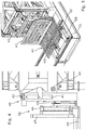
- a base 30 is provided carrying a guide 31.
- the guide 31 is constituted by a portion of a Long type truss.
- a Vierendeel-type beam 32 can slide inside the guide 31.
- the guide 31 at the front rests on two supports 33 near the container 12 and is fixed by means of a pin 35 on two rear supports 34.
- the supports 33 and 34 are part of the base 30.
- the guide 31 is formed by beams joined together and having towards the inside a plurality of upper and lower wheels 36, on which the beam 32 can slide.
- the beam 32 can slide horizontally inside the guide 31 by the actuation of a pair of chains 37 placed on the side of the beam 32.
- the beam 32 supports a structure 40, which comprises a pair of vertical lifters 41 that can vertically lift the portion 42, of the structure 40, fixed in front of the same (40).
- the lifter 41 also comprises actuators 43 to tilt forward by few degrees the lifter 41 and the portion 42 rotating around the pin 49.
- the portion 42 supports a horizontal seizing apparatus 44, commonly called fork, having a plurality of prongs 48.
- the portion 42 also comprises a pantograph structure 46 extending on command, connected to a panel 47.
- the pantograph 46 is arranged above the fork 44.
- a support system 50 of the beam 32 is located in the base 30, between the guide 31 and the container 12 . In the rest position, while the pallets of sacks 14 are loaded on the fork 44, the support system 50 remains horizontal to not interfere with the operations that take place above it.
- the support system 50 When the beam 32 begins to enter inside the container 12, the support system 50 is lifted, being possible for the latter to rotate about a pin 51, placed close to the container 12. At the ends of the support system 50 wheels 52 are placed on which the beam 32 can rest and slide.
- the plant for the loading of a container is automatic so all the means used are motorized and controlled by a computerized control center with the use of several sensors. Said elements will not be described in detail since, after the reading of this document, a person skilled in the art is able to manufacture the same.
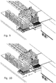
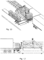
- the second carriage 20 approaches the first carriage 20 ( Figure 10 ) so that the pallet of sacks 14 are arranged side by side. Both move and align themselves to the fork 44, ( Figure 11 and 12 ) which in the meantime was positioned lower than the prongs 23 so as not to interfere with the arriving carriages 20.
- the fork 44 is as wide as the two pallets of sacks 14 side by side.
- the lifter 41 lifts the structure 40 ( Figure 12 ) and in particular the prongs of the fork 44 pass through the prongs 23 of the carriages 20.
- the lifters 41 are inclined by a few degrees (for example approximately 3°) ( Figure 14 ), so as to lift the tip of the fork 44 and better hold the pallet of sacks 14.
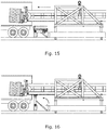
- the beam 32 is advanced ( Figure 15 ), along the guide 31, bringing the fork 44 inside the container 12.
- the support system 50 is lifted ( Figure 16 ) and the beam 32 rests on the wheels 52 and moves forward until being positioned at the point ( Figure 17 ) in which the stack of sacks 14 must be unloaded.
- the lifter 41 is inclined downward ( Figure 18 ) and the fork 44 returns to the starting position.
- the fork 44 is lowered ( Figure 19 ) to be positioned on (or close to) the floor of the container 12.
- the pantograph 46 extends ( Figure 20 ) positioning the second panel 47 against the pallet of sacks 14, and at the same time the beam 32 is retracted at the same speed, so that the pallet of sacks 14 remains in the desired position, unloading from the fork 44.
- the arrangement in height of the conveyor 16, of the movable carriages 20 and of the fork 44 allows the lateral sliding of the same (20) without interference.
- the positioning of the support system 50, of the beam 32, as close as possible to the container 12 allows the beam to extend inside the container 12 with greater ease.
- the guide 31 is supported by two front supports 33 (towards the container 12) and by means of a pair of pins 35, placed on the rear supports 34, in order not to create a constraint to the rotation about the pin to avoid hyperstatic and non-immediately quantifiable reactions during the extension of the beam 32 when resting on the support 50.
- the vehicle carrying the container 12 must arrive at the park area 11 in reverse, and to obtain a correct alignment with the fork 44, it is provided that the front portion 42 of the structure 40 can move sideways sliding along guides 45.
- the entire base 30, with the guide 31, the beam 32 and the structure 40 can move sideways by a few meters sliding along rails 55 so that the arriving vehicle can pass between the base 30 and the conveyor 16 facing forward.
- the base 30 returns to the loading position behind the opening of the container 12.
- the size of the plant which in one embodiment has a beam 32 comprising the fork 44 of length 18 m, with sides of 1.25 m and 1.5 m, a weight of 8 t and a fork 2 m wide and 1.2 m long, may be any according to requirements and the state of the art.
- the fork In the case of the presence of pallets carrying the sacks 14, the fork would have a different shape and comprising only four prongs to support the two pallets. In this case it would not be necessary the pantograph to release the sacks as just retracting the fork from the pallets would be needed.
Landscapes
- Engineering & Computer Science (AREA)
- Mechanical Engineering (AREA)
- Aviation & Aerospace Engineering (AREA)
- Stacking Of Articles And Auxiliary Devices (AREA)
- Loading Or Unloading Of Vehicles (AREA)
Claims (13)
- Installation pour le chargement automatique d'un conteneur avec des empilements ordonnés de sacs (14), comprenant : au moins un chariot mobile (20) dans une première direction ; ledit chariot mobile (20) ayant une pluralité de premières dents (23) disposées en porte-à-faux ; un guide (31) aligné avec ledit conteneur (12) ; une poutre (32) coulissant à l'intérieur dudit guide (31) dans une seconde direction perpendiculaire à ladite première direction ; un appareil de saisie (44), ayant des secondes dents (48), associé à une extrémité de ladite poutre (32) ; lesdites secondes dents (48) pouvant être insérées entre lesdites premières dents (23) ; ledit au moins un chariot mobile (20) étant mobile d'une première position permettant de recevoir lesdits empilements ordonnés de sacs (14) sur lesdites premières dents (23) jusqu'à une seconde position dans laquelle lesdites premières dents (23) sont disposées au-dessus desdites secondes dents (48) ; lesdites secondes dents (48) étant mobiles verticalement ; ladite poutre (32) étant mobile longitudinalement de façon à entrer à l'intérieur dudit conteneur (12).
- Installation selon la revendication 1, caractérisée en ce qu'elle comprend un système de support (50) de ladite poutre (32), placé à côté dudit conteneur (12), levable et supportant ladite poutre (32) lorsque cette dernière entre à l'intérieur dudit conteneur (12).
- Installation selon l'une des revendications précédentes, caractérisée en ce que ledit appareil de saisie (44) est associé à une extrémité de ladite poutre (32) au moyen d'un pantographe (46) extensible et rétractable sur commande.
- Installation selon l'une des revendications précédentes, caractérisée en ce que ledit appareil de saisie (44) est inclinable.
- Installation selon l'une des revendications précédentes, caractérisée en ce que ledit guide (31) est une partie d'une structure en treillis pourvue de galets supérieurs et inférieurs (36), en contact sur l'intérieur de ladite poutre (32).
- Installation selon l'une des revendications précédentes, caractérisée en ce qu'elle comprend un convoyeur (13) qui délivre des empilements ordonnés de sacs (14) sur ledit au moins un chariot (20).
- Installation selon la revendication 6, caractérisée en ce qu'elle comprend un convoyeur à chaînes (16) disposé en porte-à-faux à l'extrémité dudit convoyeur (13) ; lesdites chaînes pouvant être insérées entre lesdites premières dents (23).
- Installation selon l'une des revendications précédentes, caractérisée en ce qu'elle comprend deux chariots mobiles (20).
- Installation selon l'une des revendications précédentes, caractérisée en ce qu'elle comprend une base (30) supportant ledit guide (31) ; ladite base étant mobile dans ladite première direction.
- Installation selon l'une des revendications précédentes, caractérisée en ce que la largeur dudit appareil de saisie (44) est sensiblement égale à la largeur desdits deux chariots (20).
- Installation selon l'une des revendications précédentes, caractérisée en ce que ledit guide (31) est placé sur deux supports (33) à l'avant et est fixé au moyen d'une broche (35) sur deux supports arrière (34).
- Procédé pour le chargement automatique d'un conteneur avec des palettes de sacs comprenant les étapes consistant à : délivrer des palettes de sacs sur au moins un chariot mobile (20) dans une première direction ; ledit chariot mobile (20) ayant une pluralité de premières dents (23) disposées en porte-à-faux ; placer un guide (31) aligné avec ledit conteneur (12) ; une poutre (32) pouvant coulisser à l'intérieur dudit guide (31) dans une seconde direction perpendiculaire à ladite première direction ; agencer un appareil de saisie (44), ayant des secondes dents (48), associé à une extrémité de ladite poutre (32) ; lesdites secondes dents (48) pouvant être insérées entre lesdites premières dents (23) ; déplacer ledit chariot mobile (20) d'une première position permettant de recevoir lesdites palettes de sacs sur lesdites premières dents (23) jusqu'à une seconde position dans laquelle lesdites premières dents sont situées au-dessus dudit appareil de saisie (44) ; déplacer verticalement ledit appareil de saisie (44) ; déplacer longitudinalement ladite poutre (32) afin qu'elle entre à l'intérieur dudit conteneur (12).
- Procédé selon la revendication précédente, caractérisé en ce qu'il comprend en outre l'étape consistant à lever un système de support (50) de ladite poutre (32), placé à côté dudit conteneur (12), lorsque cette dernière entre à l'intérieur dudit conteneur (12).
Applications Claiming Priority (2)
| Application Number | Priority Date | Filing Date | Title |
|---|---|---|---|
| DKPA201570822 | 2015-12-14 | ||
| PCT/EP2016/080866 WO2017102771A1 (fr) | 2015-12-14 | 2016-12-14 | Système et procédé pour le chargement automatique d'un conteneur |
Publications (2)
| Publication Number | Publication Date |
|---|---|
| EP3390252A1 EP3390252A1 (fr) | 2018-10-24 |
| EP3390252B1 true EP3390252B1 (fr) | 2021-10-06 |
Family
ID=59055880
Family Applications (1)
| Application Number | Title | Priority Date | Filing Date |
|---|---|---|---|
| EP16810365.3A Active EP3390252B1 (fr) | 2015-12-14 | 2016-12-14 | Système et procédé pour le chargement automatique d'un conteneur |
Country Status (3)
| Country | Link |
|---|---|
| EP (1) | EP3390252B1 (fr) |
| ES (1) | ES2895136T3 (fr) |
| WO (1) | WO2017102771A1 (fr) |
Families Citing this family (1)
| Publication number | Priority date | Publication date | Assignee | Title |
|---|---|---|---|---|
| CN109353849B (zh) * | 2018-12-13 | 2023-09-22 | 合肥泰禾智能科技集团股份有限公司 | 一种装车行走引导系统以及装车行走引导方法 |
Family Cites Families (4)
| Publication number | Priority date | Publication date | Assignee | Title |
|---|---|---|---|---|
| SE429541B (sv) * | 1979-11-22 | 1983-09-12 | Volvo Ab | Sett och anordning for att lasta godsenheter i en godsbehallare |
| PL1963217T3 (pl) * | 2005-12-22 | 2014-03-31 | Actiw Oy | Płyta przeładunkowa i metoda załadunku w przestrzeni załadunkowej |
| EP2716591B1 (fr) * | 2012-10-03 | 2015-05-13 | Montajes de Maquinaria de Precision, S.A. | Système pour charger et décharger automatiquement des camions et des conteneurs |
| RU2016102056A (ru) * | 2013-06-24 | 2017-07-28 | Эф-Эл-Смидт А/С | Комплект оборудования и способ для погрузки в дорожное транспортное средство мешков сыпучего материала |
-
2016
- 2016-12-14 WO PCT/EP2016/080866 patent/WO2017102771A1/fr not_active Ceased
- 2016-12-14 ES ES16810365T patent/ES2895136T3/es active Active
- 2016-12-14 EP EP16810365.3A patent/EP3390252B1/fr active Active
Also Published As
| Publication number | Publication date |
|---|---|
| EP3390252A1 (fr) | 2018-10-24 |
| WO2017102771A1 (fr) | 2017-06-22 |
| ES2895136T3 (es) | 2022-02-17 |
Similar Documents
| Publication | Publication Date | Title |
|---|---|---|
| US7575407B2 (en) | Article storage facility | |
| EP1704071B1 (fr) | Chargeur de fret aerien a plate-formes multiples | |
| KR20210088751A (ko) | 고층 입체 창고에서 컨테이너의 입고 및 출고 또는 이동 방법 및 그 장치 | |
| JPH021043B2 (fr) | ||
| US20230192425A1 (en) | Apparatus and method for unloading and loading a transport unit | |
| JP7331445B2 (ja) | スタッカクレーン | |
| EP3390252B1 (fr) | Système et procédé pour le chargement automatique d'un conteneur | |
| CN213294087U (zh) | 侧面自动装卸设备 | |
| JP2023549259A (ja) | コンテナ傾動機能性を伴う自動保管および回収システムのためのアクセスステーションならびにそれを使用するための方法 | |
| CN111845962A (zh) | 装卸货车和装卸货车的货物装卸方法 | |
| EP4296200B1 (fr) | Installation de stockage d'articles | |
| JPH0336738B2 (fr) | ||
| JP2594050Y2 (ja) | 長尺重量物保管倉庫 | |
| NO20221034A1 (en) | Buffer system | |
| JP5420286B2 (ja) | 搬送装置 | |
| JP2000264406A (ja) | 横渡し機能付き自動倉庫 | |
| US20250162804A1 (en) | A delivery port for delivery of goods contained in goods holders | |
| EP4419451B1 (fr) | Ensemble, module de stockage et système de stockage et de récupération automatisé | |
| US20240400321A1 (en) | System for delivering storage containers | |
| US20240400303A1 (en) | A container buffering assembly, a storage system comprising the container buffering assembly, and associated methods | |
| JPH072368A (ja) | トラックローダー | |
| JP2001261165A (ja) | パレットの積降ろし設備及びその積降ろし方法 | |
| JPH045603B2 (fr) | ||
| JP2024025384A (ja) | 自動倉庫 | |
| JP2001010702A (ja) | 自動倉庫 |
Legal Events
| Date | Code | Title | Description |
|---|---|---|---|
| STAA | Information on the status of an ep patent application or granted ep patent |
Free format text: STATUS: UNKNOWN |
|
| STAA | Information on the status of an ep patent application or granted ep patent |
Free format text: STATUS: THE INTERNATIONAL PUBLICATION HAS BEEN MADE |
|
| PUAI | Public reference made under article 153(3) epc to a published international application that has entered the european phase |
Free format text: ORIGINAL CODE: 0009012 |
|
| STAA | Information on the status of an ep patent application or granted ep patent |
Free format text: STATUS: REQUEST FOR EXAMINATION WAS MADE |
|
| 17P | Request for examination filed |
Effective date: 20180705 |
|
| AK | Designated contracting states |
Kind code of ref document: A1 Designated state(s): AL AT BE BG CH CY CZ DE DK EE ES FI FR GB GR HR HU IE IS IT LI LT LU LV MC MK MT NL NO PL PT RO RS SE SI SK SM TR |
|
| AX | Request for extension of the european patent |
Extension state: BA ME |
|
| DAV | Request for validation of the european patent (deleted) | ||
| DAX | Request for extension of the european patent (deleted) | ||
| GRAP | Despatch of communication of intention to grant a patent |
Free format text: ORIGINAL CODE: EPIDOSNIGR1 |
|
| STAA | Information on the status of an ep patent application or granted ep patent |
Free format text: STATUS: GRANT OF PATENT IS INTENDED |
|
| INTG | Intention to grant announced |
Effective date: 20210506 |
|
| GRAS | Grant fee paid |
Free format text: ORIGINAL CODE: EPIDOSNIGR3 |
|
| GRAA | (expected) grant |
Free format text: ORIGINAL CODE: 0009210 |
|
| STAA | Information on the status of an ep patent application or granted ep patent |
Free format text: STATUS: THE PATENT HAS BEEN GRANTED |
|
| AK | Designated contracting states |
Kind code of ref document: B1 Designated state(s): AL AT BE BG CH CY CZ DE DK EE ES FI FR GB GR HR HU IE IS IT LI LT LU LV MC MK MT NL NO PL PT RO RS SE SI SK SM TR |
|
| REG | Reference to a national code |
Ref country code: GB Ref legal event code: FG4D |
|
| REG | Reference to a national code |
Ref country code: CH Ref legal event code: EP Ref country code: AT Ref legal event code: REF Ref document number: 1436060 Country of ref document: AT Kind code of ref document: T Effective date: 20211015 |
|
| REG | Reference to a national code |
Ref country code: IE Ref legal event code: FG4D |
|
| REG | Reference to a national code |
Ref country code: DE Ref legal event code: R096 Ref document number: 602016064689 Country of ref document: DE |
|
| REG | Reference to a national code |
Ref country code: LT Ref legal event code: MG9D |
|
| REG | Reference to a national code |
Ref country code: NL Ref legal event code: MP Effective date: 20211006 |
|
| REG | Reference to a national code |
Ref country code: ES Ref legal event code: FG2A Ref document number: 2895136 Country of ref document: ES Kind code of ref document: T3 Effective date: 20220217 |
|
| REG | Reference to a national code |
Ref country code: AT Ref legal event code: MK05 Ref document number: 1436060 Country of ref document: AT Kind code of ref document: T Effective date: 20211006 |
|
| PG25 | Lapsed in a contracting state [announced via postgrant information from national office to epo] |
Ref country code: RS Free format text: LAPSE BECAUSE OF FAILURE TO SUBMIT A TRANSLATION OF THE DESCRIPTION OR TO PAY THE FEE WITHIN THE PRESCRIBED TIME-LIMIT Effective date: 20211006 Ref country code: LT Free format text: LAPSE BECAUSE OF FAILURE TO SUBMIT A TRANSLATION OF THE DESCRIPTION OR TO PAY THE FEE WITHIN THE PRESCRIBED TIME-LIMIT Effective date: 20211006 Ref country code: FI Free format text: LAPSE BECAUSE OF FAILURE TO SUBMIT A TRANSLATION OF THE DESCRIPTION OR TO PAY THE FEE WITHIN THE PRESCRIBED TIME-LIMIT Effective date: 20211006 Ref country code: BG Free format text: LAPSE BECAUSE OF FAILURE TO SUBMIT A TRANSLATION OF THE DESCRIPTION OR TO PAY THE FEE WITHIN THE PRESCRIBED TIME-LIMIT Effective date: 20220106 Ref country code: AT Free format text: LAPSE BECAUSE OF FAILURE TO SUBMIT A TRANSLATION OF THE DESCRIPTION OR TO PAY THE FEE WITHIN THE PRESCRIBED TIME-LIMIT Effective date: 20211006 |
|
| PG25 | Lapsed in a contracting state [announced via postgrant information from national office to epo] |
Ref country code: IS Free format text: LAPSE BECAUSE OF FAILURE TO SUBMIT A TRANSLATION OF THE DESCRIPTION OR TO PAY THE FEE WITHIN THE PRESCRIBED TIME-LIMIT Effective date: 20220206 Ref country code: SE Free format text: LAPSE BECAUSE OF FAILURE TO SUBMIT A TRANSLATION OF THE DESCRIPTION OR TO PAY THE FEE WITHIN THE PRESCRIBED TIME-LIMIT Effective date: 20211006 Ref country code: PT Free format text: LAPSE BECAUSE OF FAILURE TO SUBMIT A TRANSLATION OF THE DESCRIPTION OR TO PAY THE FEE WITHIN THE PRESCRIBED TIME-LIMIT Effective date: 20220207 Ref country code: PL Free format text: LAPSE BECAUSE OF FAILURE TO SUBMIT A TRANSLATION OF THE DESCRIPTION OR TO PAY THE FEE WITHIN THE PRESCRIBED TIME-LIMIT Effective date: 20211006 Ref country code: NO Free format text: LAPSE BECAUSE OF FAILURE TO SUBMIT A TRANSLATION OF THE DESCRIPTION OR TO PAY THE FEE WITHIN THE PRESCRIBED TIME-LIMIT Effective date: 20220106 Ref country code: NL Free format text: LAPSE BECAUSE OF FAILURE TO SUBMIT A TRANSLATION OF THE DESCRIPTION OR TO PAY THE FEE WITHIN THE PRESCRIBED TIME-LIMIT Effective date: 20211006 Ref country code: LV Free format text: LAPSE BECAUSE OF FAILURE TO SUBMIT A TRANSLATION OF THE DESCRIPTION OR TO PAY THE FEE WITHIN THE PRESCRIBED TIME-LIMIT Effective date: 20211006 Ref country code: HR Free format text: LAPSE BECAUSE OF FAILURE TO SUBMIT A TRANSLATION OF THE DESCRIPTION OR TO PAY THE FEE WITHIN THE PRESCRIBED TIME-LIMIT Effective date: 20211006 Ref country code: GR Free format text: LAPSE BECAUSE OF FAILURE TO SUBMIT A TRANSLATION OF THE DESCRIPTION OR TO PAY THE FEE WITHIN THE PRESCRIBED TIME-LIMIT Effective date: 20220107 |
|
| REG | Reference to a national code |
Ref country code: DE Ref legal event code: R097 Ref document number: 602016064689 Country of ref document: DE |
|
| PG25 | Lapsed in a contracting state [announced via postgrant information from national office to epo] |
Ref country code: SM Free format text: LAPSE BECAUSE OF FAILURE TO SUBMIT A TRANSLATION OF THE DESCRIPTION OR TO PAY THE FEE WITHIN THE PRESCRIBED TIME-LIMIT Effective date: 20211006 Ref country code: SK Free format text: LAPSE BECAUSE OF FAILURE TO SUBMIT A TRANSLATION OF THE DESCRIPTION OR TO PAY THE FEE WITHIN THE PRESCRIBED TIME-LIMIT Effective date: 20211006 Ref country code: RO Free format text: LAPSE BECAUSE OF FAILURE TO SUBMIT A TRANSLATION OF THE DESCRIPTION OR TO PAY THE FEE WITHIN THE PRESCRIBED TIME-LIMIT Effective date: 20211006 Ref country code: MC Free format text: LAPSE BECAUSE OF FAILURE TO SUBMIT A TRANSLATION OF THE DESCRIPTION OR TO PAY THE FEE WITHIN THE PRESCRIBED TIME-LIMIT Effective date: 20211006 Ref country code: EE Free format text: LAPSE BECAUSE OF FAILURE TO SUBMIT A TRANSLATION OF THE DESCRIPTION OR TO PAY THE FEE WITHIN THE PRESCRIBED TIME-LIMIT Effective date: 20211006 Ref country code: DK Free format text: LAPSE BECAUSE OF FAILURE TO SUBMIT A TRANSLATION OF THE DESCRIPTION OR TO PAY THE FEE WITHIN THE PRESCRIBED TIME-LIMIT Effective date: 20211006 Ref country code: CZ Free format text: LAPSE BECAUSE OF FAILURE TO SUBMIT A TRANSLATION OF THE DESCRIPTION OR TO PAY THE FEE WITHIN THE PRESCRIBED TIME-LIMIT Effective date: 20211006 |
|
| REG | Reference to a national code |
Ref country code: CH Ref legal event code: PL |
|
| PLBE | No opposition filed within time limit |
Free format text: ORIGINAL CODE: 0009261 |
|
| STAA | Information on the status of an ep patent application or granted ep patent |
Free format text: STATUS: NO OPPOSITION FILED WITHIN TIME LIMIT |
|
| 26N | No opposition filed |
Effective date: 20220707 |
|
| REG | Reference to a national code |
Ref country code: BE Ref legal event code: MM Effective date: 20211231 |
|
| GBPC | Gb: european patent ceased through non-payment of renewal fee |
Effective date: 20220106 |
|
| PG25 | Lapsed in a contracting state [announced via postgrant information from national office to epo] |
Ref country code: LU Free format text: LAPSE BECAUSE OF NON-PAYMENT OF DUE FEES Effective date: 20211214 Ref country code: IE Free format text: LAPSE BECAUSE OF NON-PAYMENT OF DUE FEES Effective date: 20211214 Ref country code: GB Free format text: LAPSE BECAUSE OF NON-PAYMENT OF DUE FEES Effective date: 20220106 Ref country code: AL Free format text: LAPSE BECAUSE OF FAILURE TO SUBMIT A TRANSLATION OF THE DESCRIPTION OR TO PAY THE FEE WITHIN THE PRESCRIBED TIME-LIMIT Effective date: 20211006 |
|
| PG25 | Lapsed in a contracting state [announced via postgrant information from national office to epo] |
Ref country code: SI Free format text: LAPSE BECAUSE OF FAILURE TO SUBMIT A TRANSLATION OF THE DESCRIPTION OR TO PAY THE FEE WITHIN THE PRESCRIBED TIME-LIMIT Effective date: 20211006 Ref country code: BE Free format text: LAPSE BECAUSE OF NON-PAYMENT OF DUE FEES Effective date: 20211231 |
|
| PG25 | Lapsed in a contracting state [announced via postgrant information from national office to epo] |
Ref country code: LI Free format text: LAPSE BECAUSE OF NON-PAYMENT OF DUE FEES Effective date: 20211231 Ref country code: CH Free format text: LAPSE BECAUSE OF NON-PAYMENT OF DUE FEES Effective date: 20211231 |
|
| PG25 | Lapsed in a contracting state [announced via postgrant information from national office to epo] |
Ref country code: HU Free format text: LAPSE BECAUSE OF FAILURE TO SUBMIT A TRANSLATION OF THE DESCRIPTION OR TO PAY THE FEE WITHIN THE PRESCRIBED TIME-LIMIT; INVALID AB INITIO Effective date: 20161214 |
|
| P01 | Opt-out of the competence of the unified patent court (upc) registered |
Effective date: 20230507 |
|
| PG25 | Lapsed in a contracting state [announced via postgrant information from national office to epo] |
Ref country code: CY Free format text: LAPSE BECAUSE OF FAILURE TO SUBMIT A TRANSLATION OF THE DESCRIPTION OR TO PAY THE FEE WITHIN THE PRESCRIBED TIME-LIMIT Effective date: 20211006 |
|
| PG25 | Lapsed in a contracting state [announced via postgrant information from national office to epo] |
Ref country code: MK Free format text: LAPSE BECAUSE OF FAILURE TO SUBMIT A TRANSLATION OF THE DESCRIPTION OR TO PAY THE FEE WITHIN THE PRESCRIBED TIME-LIMIT Effective date: 20211006 |
|
| PG25 | Lapsed in a contracting state [announced via postgrant information from national office to epo] |
Ref country code: MT Free format text: LAPSE BECAUSE OF FAILURE TO SUBMIT A TRANSLATION OF THE DESCRIPTION OR TO PAY THE FEE WITHIN THE PRESCRIBED TIME-LIMIT Effective date: 20211006 |
|
| REG | Reference to a national code |
Ref country code: DE Ref legal event code: R081 Ref document number: 602016064689 Country of ref document: DE Owner name: FLSMIDTH CEMENT A/S, DK Free format text: FORMER OWNER: FLSMIDTH A/S, VALBY, DK |
|
| REG | Reference to a national code |
Ref country code: ES Ref legal event code: PC2A Owner name: FLSMIDTH CEMENT A/S Effective date: 20250924 |
|
| PGFP | Annual fee paid to national office [announced via postgrant information from national office to epo] |
Ref country code: IT Payment date: 20251218 Year of fee payment: 10 |
|
| PGFP | Annual fee paid to national office [announced via postgrant information from national office to epo] |
Ref country code: FR Payment date: 20251230 Year of fee payment: 10 |
|
| PGFP | Annual fee paid to national office [announced via postgrant information from national office to epo] |
Ref country code: TR Payment date: 20251126 Year of fee payment: 10 |
|
| PGFP | Annual fee paid to national office [announced via postgrant information from national office to epo] |
Ref country code: ES Payment date: 20260122 Year of fee payment: 10 |
|
| PGFP | Annual fee paid to national office [announced via postgrant information from national office to epo] |
Ref country code: DE Payment date: 20251229 Year of fee payment: 10 |