EP3400360B1 - Schnellverriegelungsadapter für grossbohreinbauwerkzeug - Google Patents
Schnellverriegelungsadapter für grossbohreinbauwerkzeug Download PDFInfo
- Publication number
- EP3400360B1 EP3400360B1 EP16895676.1A EP16895676A EP3400360B1 EP 3400360 B1 EP3400360 B1 EP 3400360B1 EP 16895676 A EP16895676 A EP 16895676A EP 3400360 B1 EP3400360 B1 EP 3400360B1
- Authority
- EP
- European Patent Office
- Prior art keywords
- collet
- liner hanger
- assembly
- single piece
- hanger body
- Prior art date
- Legal status (The legal status is an assumption and is not a legal conclusion. Google has not performed a legal analysis and makes no representation as to the accuracy of the status listed.)
- Active
Links
Images


Classifications
-
- E—FIXED CONSTRUCTIONS
- E21—EARTH OR ROCK DRILLING; MINING
- E21B—EARTH OR ROCK DRILLING; OBTAINING OIL, GAS, WATER, SOLUBLE OR MELTABLE MATERIALS OR A SLURRY OF MINERALS FROM WELLS
- E21B23/00—Apparatus for displacing, setting, locking, releasing or removing tools, packers or the like in boreholes or wells
- E21B23/02—Apparatus for displacing, setting, locking, releasing or removing tools, packers or the like in boreholes or wells for locking the tools or the like in landing nipples or in recesses between adjacent sections of tubing
-
- E—FIXED CONSTRUCTIONS
- E21—EARTH OR ROCK DRILLING; MINING
- E21B—EARTH OR ROCK DRILLING; OBTAINING OIL, GAS, WATER, SOLUBLE OR MELTABLE MATERIALS OR A SLURRY OF MINERALS FROM WELLS
- E21B23/00—Apparatus for displacing, setting, locking, releasing or removing tools, packers or the like in boreholes or wells
-
- E—FIXED CONSTRUCTIONS
- E21—EARTH OR ROCK DRILLING; MINING
- E21B—EARTH OR ROCK DRILLING; OBTAINING OIL, GAS, WATER, SOLUBLE OR MELTABLE MATERIALS OR A SLURRY OF MINERALS FROM WELLS
- E21B43/00—Methods or apparatus for obtaining oil, gas, water, soluble or meltable materials or a slurry of minerals from wells
- E21B43/02—Subsoil filtering
- E21B43/10—Setting of casings, screens, liners or the like in wells
Definitions
- the running tool now has a built in test port for O-ring seal hydro testing, which saves design time and cost.
- two O-rings instead of one, now form a seal between the collet prop mandrel and the inner diameter of the liner hanger.
- a pressure port located between the two O-rings communicates to a sealed annular chamber bounded by the inner collet mandrel and the outer collet mandrel sub assembly and O-rings that are placed between the components.
Landscapes
- Geology (AREA)
- Life Sciences & Earth Sciences (AREA)
- Engineering & Computer Science (AREA)
- Mining & Mineral Resources (AREA)
- Environmental & Geological Engineering (AREA)
- Fluid Mechanics (AREA)
- Physics & Mathematics (AREA)
- General Life Sciences & Earth Sciences (AREA)
- Geochemistry & Mineralogy (AREA)
- Earth Drilling (AREA)
- Chain Conveyers (AREA)
- Load-Engaging Elements For Cranes (AREA)
- Prostheses (AREA)
- Packaging Of Annular Or Rod-Shaped Articles, Wearing Apparel, Cassettes, Or The Like (AREA)
Claims (14)
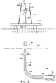
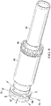
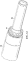
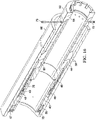
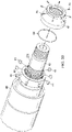
- Verfahren zum Befördern eines einteiligen Futterrohraufhängungskörpers (88), wobei das Verfahren Folgendes umfasst:Zusammenbauen eines inneren Unteranordnungsabschnitts (43, 44, 45, 46, 47, 48, 49) einer Kupplungsanordnung (100), um einen zusammengesetzten inneren Unteranordnungsabschnitt (43, 44, 45, 46, 47, 48, 49) der Kupplungsanordnung (100) zu bilden;Einsetzen des zusammengebauten inneren Unteranordnungsabschnitts (43, 44, 45, 46, 47, 48, 49) der Kupplungsanordnung (100) durch eine erste Öffnung eines einteiligen Futterrohraufhängungskörpers (88), bis es in einen Innendurchmesser des einteiligen Futterrohraufhängungskörpers (88) eingreift, wobei die erste Öffnung dazu bestimmt ist, an der Unterseite des einteiligen Futterrohraufhängungskörpers (88) angeordnet zu sein, wenn er im Gebrauch vertikal in einem Bohrloch angeordnet ist;Einsetzen eines Spannzangen-Stützdorns (50) in die erste Öffnung des einteiligen Futterrohraufhängungskörpers (88), bis es mit dem zusammengebauten inneren Unteranordnungsabschnitt (43, 44, 45, 46, 47, 48, 49) der Kupplungsanordnung (100) in Eingriff kommt, um die Kupplungsanordnung (100) zu bilden;Einsetzen eines Einbauwerkzeugs (90) mit einer auf der Unterseite des Einbauwerkzeugs (90) installierten Futterrohraufhängungs-Unteranordnung (40) in eine zweite Öffnung des einteiligen Futterrohraufhängungskörpers (88), bis die Futterrohraufhängungs-Unteranordnung (40) mit der Kupplungsanordnung (100) in Eingriff kommt, wobei die zweite Öffnung dazu bestimmt ist, an der Oberseite des einteiligen Futterrohraufhängungskörpers (88) angeordnet zu sein, wenn er im Gebrauch vertikal in einem Bohrloch angeordnet ist; undBefestigen der Futterrohraufhängungs-Unteranordnung (40) an der Kupplungsanordnung (100).
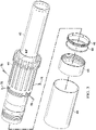
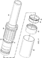
- Verfahren zum Befördern eines einteiligen Futterrohraufhängungskörpers (88) nach Anspruch 1, wobei der zusammengesetzte innere Unteranordnungsabschnitt (43, 44, 45, 46, 47, 48, 49) der Kupplungsanordnung (100) Folgendes umfasst:einen äußeren Spannzangendorn (43), der an einem ersten Ende einen mit Gewinde versehenen Außendurchmesser aufweist;eine Spannzange (44), die radial außen über dem äußeren Spannzangendorn (43) angeordnet ist, wobei die Spannzange (44) einen Satz von Spannzangenfingern (44f) an einem ersten Ende und einen mit Gewinde versehenen Außendurchmesser an einem zweiten Ende umfasst, wobei die Spannzangenfinger (44f) eine erhöhte Kante haben und wobei ferner die Spannzange (44) mit dem äußeren Spannzangendorn (43) über einen Satz von Gewindeschrauben (78) gekoppelt ist;eine Verriegelungsklaue (48), die radial außen über dem äußeren Spannzangendorn (43) angeordnet ist, wobei die Verriegelungsklaue (48) neben dem zweiten Ende der Spannzange (44) angeordnet ist;eine Ringfeder (49), die radial außerhalb von und auf dem Verriegelungsklauen (48) installiert ist;eine radial außen über der Verriegelungsklaue (48) und der Ringfeder (49) positionierte Verriegelungsklauenhalterung (45), wobei die Verriegelungsklauenhalterung (45) auf das zweite Ende der Hülse (44) aufgeschraubt ist;eine Lastübertragungshülse (46), die radial außen über der Verriegelungsklauenhalterung (45) und über der Spannzange (44) positioniert ist, wobei die Lastübertragungshülse (46) an der erhöhten Kante des Satzes von Spannzangenfingern (44f) anliegt; undeine Mutter (47), die auf das erste Ende des äußeren Spannzangendorns (43) aufgeschraubt ist.
- Verfahren zum Befördern eines einteiligen Futterrohraufhängungskörpers (88) nach Anspruch 2, wobei der Schritt des Einsetzens des zusammengebauten inneren Unteranordnungsabschnitts (43, 44, 45, 46, 47, 48, 49) des Kopplers vorgesehen ist die Anordnung (100) das Einsetzen des zusammengesetzten inneren Unteranordnungsabschnitts (43, 44, 45, 46, 47, 48, 49) der Kupplungsanordnung (100) durch die erste Öffnung des einteiligen Futterrohraufhängungskörpers (88) umfasst, bis die Spannzange (44) an dem zusammengebauten inneren Unteranordnungsabschnitt (43, 44, 45, 46, 47, 48, 49) der Kupplungsanordnung (100) mit einem passenden Spannzangenprofil innerhalb des Innendurchmessers der Futterrohraufhängung (88) in Eingriff kommt.
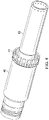
- Verfahren zum Befördern eines einteiligen Futterrohraufhängungskörpers (88) nach Anspruch 2, wobei der Schritt des Einsetzens des Spannzangen-Stützdorns (50) das Einsetzen des Spannzangen-Stützdorns (50) in die erste Öffnung des einteiligen Futterrohraufhängungskörpers (88) über dem äußeren Spannzangendorn (43) umfasst, und bis es mit der Hülse (44) des zusammengebauten inneren Unteranordnungsabschnitts (43, 44, 45, 46, 47, 48, 49) der Kupplungsanordnung (100) in Eingriff kommt, um die Kupplungsanordnung (100) zu bilden.
- Verfahren zum Befördern eines einteiligen Futterrohraufhängungskörpers (88) nach Anspruch 4, ferner umfassend das Befestigen des Spannzangen-Stützdorns (50) an dem äußeren Spannzangendorn (43) des zusammengebauten inneren Unteranordnungsabschnitts (43, 44, 45, 46, 47, 48, 49) der Kupplungsanordnung (100) unter Verwendung von einem Satz von Gewindehohlstopfen (79) .
- Verfahren zum Befördern eines einteiligen Futterrohraufhängungskörpers (88) nach Anspruch 2, wobei der Schritt des Einsetzens des Einbauwerkzeugs (90) mit der auf der Unterseite des Einbauwerkzeugs (90) installierten Futterrohraufhängungs-Unteranordnung (40) das Einsetzen des Einbauwerkzeugs (90) umfasst, das die Futterrohraufhängungs-Unteranordnung (40) aufweist, die an der Unterseite des Einbauwerkzeugs (90) in der zweiten Öffnung des einteiligen Futterrohraufhängungskörpers (88) installiert ist, bis sie vollständig mit dem äußeren Spannzangendorn (43) des zusammengebauten inneren Unteranordnungsabschnitts (43, 44, 45, 46, 47, 48, 49) der Kupplungsanordnung (100) in Eingriff ist.
- Verfahren zum Befördern eines einteiligen Futterrohraufhängungskörpers (88) nach Anspruch 2, wobei das Befestigen der Futterrohraufhängungs-Unteranordnung (40) an der Kupplungsanordnung (100) das Befestigen der Futterrohraufhängungs-Unteranordnung (40) an dem Spannzangen-Stützdorn (43) unter Verwendung einer Haltemutter (42) umfasst.
- Verfahren zum Befördern eines einteiligen Futterrohraufhängungskörpers (88) nach Anspruch 2, wobei der Schritt des Zusammenbauens des inneren Unteranordnungsabschnitts (43, 44, 45, 46, 47, 48, 49) der Kupplungsanordnung (100) zum Bilden des zusammengebauten inneren Unteranordnungsabschnitts (43, 44, 45, 46, 47, 48, 49) der Kupplungsanordnung (100) Folgendes umfasst:Installieren der Spannzange (44) über dem äußeren Spannzangendorn (43) und Verbinden der Spannzange mit dem äußeren Spannzangendorn mit dem Satz von Gewindeschrauben (78);Installieren des Verriegelungsnockens (48) über dem äußeren Spannzangendorn (43) und neben der Spannzange (44) ;Anbringen der Ringfeder (49) an der Verriegelungsklaue (48) ;Einfädeln der Verriegelungsklauenhalterung (45) in die Hülse (44) am zweiten Ende der Hülse (44), wobei die Verriegelungsklauenhalterung (45) über der Verriegelungsklaue (48) und der Ringfeder (49) positioniert ist;Installieren der Lastübertragungshülse (46) an der Spannzange (44), wobei die Lastübertragungshülse (46) über der Verriegelungsklauenhalterung (45) positioniert ist; undAufschrauben der Mutter (47) auf das erste Ende des äußeren Spannzangendorns (43).
- Verfahren zum Befördern eines einteiligen Futterrohraufhängungskörpers (88) nach Anspruch 8, ferner umfassend das Bereitstellen eines O-Rings (58) in einem Außendurchmesser der Mutter (47) und, während des Schritts des Einsetzens des zusammengebauten inneren Unteranordnungsabschnitts (43, 44, 45, 46, 47, 48, 49) der Kupplungsanordnung (100) durch die erste Öffnung eines einteiligen Futterrohraufhängungskörpers (88), bis es in einen Innendurchmesser des einteiligen Futterrohraufhängungskörpers (88) eingreift, Komprimieren des O-Rings (58) zwischen der Mutter (47) und dem einteiligen Futterrohraufhängungskörper (88).
- Kupplungsanordnung (100) zum Koppeln eines einteiligen Futterrohraufhängungskörpers (88) mit einem Einbauwerkzeug (90), wobei die Kupplungsanordnung (100) Folgendes umfasst:einen äußeren Spannzangendorn (43), der an einem ersten Ende einen mit Gewinde versehenen Außendurchmesser aufweist;eine Spannzange (44), die radial außen über dem äußeren Spannzangendorn (43) angeordnet ist, wobei die Spannzange (44) einen Satz von Spannzangenfingern (44f) an einem ersten Ende und einen mit Gewinde versehenen Außendurchmesser an einem zweiten Ende umfasst, wobei die Spannzangenfinger (44f) eine erhöhte Kante haben und wobei ferner die Spannzange (44) mit dem äußeren Spannzangendorn (43) über einen Satz von Gewindeschrauben (78) gekoppelt ist;eine radial außen über dem Spannfutterdorn (43) angeordnete Verriegelungsklaue (48), wobei sich die Verriegelungsklaue (48) neben dem zweiten Ende der Spannzange (44) befindet;eine Ringfeder (49), die radial außerhalb von und auf dem Verriegelungsklauen (48) installiert ist;eine radial außen über der Verriegelungsklaue (48) und der Ringfeder (49) positionierte Verriegelungsklauenhalterung (45), wobei die Verriegelungsklauenhalterung (45) auf das zweite Ende der Hülse (44) aufgeschraubt ist;eine Lastübertragungshülse (46), die radial außen über der Verriegelungsklauenhalterung (45) und über der Spannzange (44) positioniert ist, wobei die Lastübertragungshülse (46) an der erhöhten Kante des Satzes von Spannzangenfingern (44f) anliegt; undeine Mutter (47), die auf das erste Ende des äußeren Spannzangendorns (43) aufgeschraubt ist.
- Kupplungsanordnung (100) zum Koppeln eines einteiligen Futterrohraufhängungskörpers (88) mit einem Einbauwerkzeug (90) nach Anspruch 10, wobei die Mutter (47), die Lastübertragungshülse (46), die Verriegelungsklauenhalterung (45), die Ringfeder (49), die Verriegelungsklaue (48), die Spannzange (44) und der äußere Spannzangendorn (43) einen inneren Unteranordnungsabschnitt (43, 44, 45, 46, 47, 48, 49) der Kupplungsanordnung (100) bilden.
- System, umfassend:einen einteiligen Futterrohraufhängungskörper (88) mit einer ersten Öffnung, wobei die erste Öffnung dazu bestimmt ist, sich am Boden des einteiligen Futterrohraufhängungskörpers (88) zu befinden, wenn es vertikal in einem verwendeten Bohrloch angeordnet ist;die Kupplungsanordnung (100) zum Koppeln eines einteiligen Futterrohraufhängungskörpers (88) mit einem Einbauwerkzeug (90) nach Anspruch 11, wobei der innere Unteranordnungsabschnitt (43, 44, 45, 46, 47, 48, 49) der Kupplungsanordnung (100) durch die erste Öffnung des einteiligen Futterrohraufhängungskörpers (88) einsetzbar ist, und wobei die Kupplungsanordnung ferner einen Spannzangen-Stützdorn (50) umfasst, der in die erste Öffnung des einteiligen Futterrohraufhängungskörpers (88) einsetzbar ist, bis es mit dem zusammengebauten inneren Unteranordnungsabschnitt (43, 44, 45, 46, 47, 48, 49) der Kupplungsanordnung (100) in Eingriff kommt, wobei der Spannzangen-Stützdorn (50) zusammenpassende Merkmale zum Eingriff mit dem inneren Unteranordnungsabschnitt (43, 44, 45, 46, 47, 48, 49) der Kupplungsanordnung (100) innerhalb des einteiligen Futterrohraufhängungskörpers (88) aufweist;ein Einbauwerkzeug (90) mit einer Futterrohraufhängungs-Unteranordnung (40), die an der Unterseite des Einbauwerkzeugs (90) installiert ist, wobei das Einbauwerkzeug (90) mit der Futterrohraufhängungs-Unteranordnung (40) in eine zweite Öffnung des einteiligen Futterrohraufhängungskörpers (88) einsetzbar ist, bis die Futterrohraufhängungs-Unteranordnung (40) mit der Kupplungsanordnung (100) in Eingriff kommt, wobei die zweite Öffnung dazu bestimmt ist, an der Oberseite des einteiligen Futterrohraufhängungskörpers (88) angeordnet zu sein, wenn er im Gebrauch vertikal in einem Bohrloch angeordnet ist.
- System nach Anspruch 12, wobei die Kupplungsanordnung (100) zum Koppeln eines einteiligen Futterrohraufhängungskörpers (88) mit einem Einbauwerkzeug (90) ferner zweite Eingriffsmerkmale zum Eingriff mit der an dem Einbauwerkzeug (90) befestigten Futterrohraufhängungs-Unteranordnung (40) umfasst.
- System nach Anspruch 13, ferner umfassend eine Haltemutter (42), die konfiguriert ist, um die Kupplungsanordnung (100) an der Futterrohraufhängungs-Unteranordnung (40) zu befestigen.
Priority Applications (1)
| Application Number | Priority Date | Filing Date | Title |
|---|---|---|---|
| HUE16895676A HUE061650T2 (hu) | 2016-03-23 | 2016-03-23 | Nagy furatú futószerszám gyorszáras adapter |
Applications Claiming Priority (1)
| Application Number | Priority Date | Filing Date | Title |
|---|---|---|---|
| PCT/US2016/023812 WO2017164869A1 (en) | 2016-03-23 | 2016-03-23 | Big bore running tool quick lock adaptor |
Publications (3)
| Publication Number | Publication Date |
|---|---|
| EP3400360A1 EP3400360A1 (de) | 2018-11-14 |
| EP3400360A4 EP3400360A4 (de) | 2019-08-21 |
| EP3400360B1 true EP3400360B1 (de) | 2023-01-18 |
Family
ID=59900698
Family Applications (1)
| Application Number | Title | Priority Date | Filing Date |
|---|---|---|---|
| EP16895676.1A Active EP3400360B1 (de) | 2016-03-23 | 2016-03-23 | Schnellverriegelungsadapter für grossbohreinbauwerkzeug |
Country Status (16)
| Country | Link |
|---|---|
| US (1) | US10989022B2 (de) |
| EP (1) | EP3400360B1 (de) |
| CN (1) | CN108699894B (de) |
| AU (1) | AU2016398436B2 (de) |
| BR (1) | BR112018016638B1 (de) |
| CA (1) | CA3014985C (de) |
| CO (1) | CO2018008237A2 (de) |
| DE (1) | DE112016006257B4 (de) |
| GB (1) | GB2564272B (de) |
| HU (1) | HUE061650T2 (de) |
| MX (1) | MX2018010158A (de) |
| MY (1) | MY191678A (de) |
| NO (1) | NO348860B1 (de) |
| SA (1) | SA518392198B1 (de) |
| SG (1) | SG11201803825PA (de) |
| WO (1) | WO2017164869A1 (de) |
Families Citing this family (5)
| Publication number | Priority date | Publication date | Assignee | Title |
|---|---|---|---|---|
| US10883333B2 (en) * | 2018-05-17 | 2021-01-05 | Weatherford Technology Holdings, Llc | Buoyant system for installing a casing string |
| US10837245B2 (en) | 2018-06-28 | 2020-11-17 | Saudi Arabian Oil Company | Liner hanger system |
| US11927081B2 (en) * | 2022-07-21 | 2024-03-12 | Baker Hughes Oilfield Operations Llc | Liner running tool, method, and system |
| US12448848B2 (en) | 2022-10-07 | 2025-10-21 | Halliburton Energy Services, Inc. | Downhole tool including a packer assembly, a completion assembly, and a removably coupled whipstock assembly |
| US20240117678A1 (en) | 2022-10-07 | 2024-04-11 | Halliburton Energy Services, Inc. | Downhole tool including a fluid loss device |
Family Cites Families (13)
| Publication number | Priority date | Publication date | Assignee | Title |
|---|---|---|---|---|
| US4311194A (en) * | 1979-08-20 | 1982-01-19 | Otis Engineering Corporation | Liner hanger and running and setting tool |
| US4823881A (en) * | 1988-02-11 | 1989-04-25 | Halliburton Company | Hydraulic setting tool |
| US4862966A (en) * | 1988-05-16 | 1989-09-05 | Lindsey Completion Systems, Inc. | Liner hanger with collapsible ball valve seat |
| US4911237A (en) * | 1989-03-16 | 1990-03-27 | Baker Hughes Incorporated | Running tool for liner hanger |
| EP2020482B1 (de) * | 2001-05-18 | 2012-09-26 | Dril-Quip, Inc. | Leitungshänger, Einbauwerkzeug und Verfahren |
| US8393389B2 (en) | 2007-04-20 | 2013-03-12 | Halliburton Evergy Services, Inc. | Running tool for expandable liner hanger and associated methods |
| CN201165866Y (zh) * | 2008-03-04 | 2008-12-17 | 北京华油油气技术开发有限公司 | 水平井分采合采管柱 |
| CN201428403Y (zh) * | 2009-05-30 | 2010-03-24 | 中国石油集团西部钻探工程有限公司克拉玛依钻井工艺研究院 | 一种欠平衡固井尾管悬挂器送入工具 |
| US8561690B2 (en) | 2011-03-04 | 2013-10-22 | Halliburton Energy Services, Inc. | Expansion cone assembly for setting a liner hanger in a wellbore casing |
| AU2012258555B2 (en) * | 2011-05-25 | 2016-04-21 | Weatherford Technology Holdings, Llc | Tubular coupling device |
| US9650854B2 (en) * | 2013-05-28 | 2017-05-16 | Weatherford Technology Holdings, Llc | Packoff for liner deployment assembly |
| US20150060086A1 (en) * | 2013-09-04 | 2015-03-05 | Halliburton Energy Services, Inc. | Running Tool with Retractable Collet for Liner String Installation in a Wellbore |
| WO2015034489A1 (en) * | 2013-09-04 | 2015-03-12 | Halliburton Energy Services, Inc. | Running tool with retractable collet for liner string installation in a wellbore |
-
2016
- 2016-03-23 EP EP16895676.1A patent/EP3400360B1/de active Active
- 2016-03-23 MX MX2018010158A patent/MX2018010158A/es unknown
- 2016-03-23 DE DE112016006257.5T patent/DE112016006257B4/de active Active
- 2016-03-23 AU AU2016398436A patent/AU2016398436B2/en active Active
- 2016-03-23 CN CN201680081707.7A patent/CN108699894B/zh active Active
- 2016-03-23 SG SG11201803825PA patent/SG11201803825PA/en unknown
- 2016-03-23 BR BR112018016638-3A patent/BR112018016638B1/pt active IP Right Grant
- 2016-03-23 HU HUE16895676A patent/HUE061650T2/hu unknown
- 2016-03-23 WO PCT/US2016/023812 patent/WO2017164869A1/en not_active Ceased
- 2016-03-23 GB GB1812963.5A patent/GB2564272B/en active Active
- 2016-03-23 US US15/779,002 patent/US10989022B2/en active Active
- 2016-03-23 CA CA3014985A patent/CA3014985C/en active Active
- 2016-03-23 MY MYPI2018702689A patent/MY191678A/en unknown
-
2018
- 2018-08-03 CO CONC2018/0008237A patent/CO2018008237A2/es unknown
- 2018-08-13 SA SA518392198A patent/SA518392198B1/ar unknown
- 2018-08-22 NO NO20181101A patent/NO348860B1/en unknown
Also Published As
| Publication number | Publication date |
|---|---|
| AU2016398436B2 (en) | 2021-11-11 |
| US10989022B2 (en) | 2021-04-27 |
| DE112016006257T5 (de) | 2018-10-04 |
| BR112018016638B1 (pt) | 2022-09-06 |
| MX2018010158A (es) | 2018-11-09 |
| WO2017164869A1 (en) | 2017-09-28 |
| BR112018016638A2 (pt) | 2018-12-26 |
| MY191678A (en) | 2022-07-07 |
| NO20181101A1 (en) | 2018-08-22 |
| GB201812963D0 (en) | 2018-09-26 |
| GB2564272B (en) | 2021-06-30 |
| AU2016398436A1 (en) | 2018-05-17 |
| DE112016006257B4 (de) | 2024-01-18 |
| CO2018008237A2 (es) | 2018-08-21 |
| CA3014985A1 (en) | 2017-09-23 |
| CN108699894B (zh) | 2021-03-05 |
| SA518392198B1 (ar) | 2025-01-13 |
| SG11201803825PA (en) | 2018-06-28 |
| CA3014985C (en) | 2021-06-08 |
| NO348860B1 (en) | 2025-06-23 |
| EP3400360A4 (de) | 2019-08-21 |
| GB2564272A (en) | 2019-01-09 |
| HUE061650T2 (hu) | 2023-07-28 |
| US20180347323A1 (en) | 2018-12-06 |
| EP3400360A1 (de) | 2018-11-14 |
| CN108699894A (zh) | 2018-10-23 |
Similar Documents
| Publication | Publication Date | Title |
|---|---|---|
| US9187963B2 (en) | Low profile clamp for a wellbore tubular | |
| US11352849B2 (en) | Methods and systems for drilling a multilateral well | |
| NO348860B1 (en) | Big bore running tool quick lock adaptor | |
| US8453728B2 (en) | Apparatus and method for depth referencing downhole tubular strings | |
| US11585182B1 (en) | Casing head support unit (CHSU) design for life cycle well integrity assurance | |
| CA2735916C (en) | Narrow well bore | |
| AU2024205117A1 (en) | Aligning two parts of a tubular assembly | |
| US8215400B2 (en) | System and method for opening a window in a casing string for multilateral wellbore construction | |
| US20230399906A1 (en) | Single Trip, Debris Tolerant Lock Mandrel With Equalizing Prong | |
| GB2586965A (en) | Wellhead apparatus, assembly and method for supporting downhole tubing | |
| US20240328274A1 (en) | Big bore low pressure surface wellhead housing systems | |
| US12247467B2 (en) | Sleeved gun connection | |
| GB2602609A (en) | Aligning two parts of a tubular assembly |
Legal Events
| Date | Code | Title | Description |
|---|---|---|---|
| STAA | Information on the status of an ep patent application or granted ep patent |
Free format text: STATUS: THE INTERNATIONAL PUBLICATION HAS BEEN MADE |
|
| PUAI | Public reference made under article 153(3) epc to a published international application that has entered the european phase |
Free format text: ORIGINAL CODE: 0009012 |
|
| STAA | Information on the status of an ep patent application or granted ep patent |
Free format text: STATUS: REQUEST FOR EXAMINATION WAS MADE |
|
| 17P | Request for examination filed |
Effective date: 20180809 |
|
| AK | Designated contracting states |
Kind code of ref document: A1 Designated state(s): AL AT BE BG CH CY CZ DE DK EE ES FI FR GB GR HR HU IE IS IT LI LT LU LV MC MK MT NL NO PL PT RO RS SE SI SK SM TR |
|
| AX | Request for extension of the european patent |
Extension state: BA ME |
|
| DAV | Request for validation of the european patent (deleted) | ||
| DAX | Request for extension of the european patent (deleted) | ||
| REG | Reference to a national code |
Ref country code: DE Ref legal event code: R079 Ref document number: 602016077566 Country of ref document: DE Free format text: PREVIOUS MAIN CLASS: E21B0017020000 Ipc: E21B0043100000 |
|
| A4 | Supplementary search report drawn up and despatched |
Effective date: 20190719 |
|
| RIC1 | Information provided on ipc code assigned before grant |
Ipc: E21B 23/00 20060101ALI20190715BHEP Ipc: E21B 43/10 20060101AFI20190715BHEP |
|
| STAA | Information on the status of an ep patent application or granted ep patent |
Free format text: STATUS: EXAMINATION IS IN PROGRESS |
|
| 17Q | First examination report despatched |
Effective date: 20200304 |
|
| RBV | Designated contracting states (corrected) |
Designated state(s): AL AT BE BG CH CY CZ DE DK EE ES FI FR GR HR HU IE IS IT LI LT LU LV MC MK MT NL NO PL PT RO RS SE SI SK SM TR |
|
| GRAP | Despatch of communication of intention to grant a patent |
Free format text: ORIGINAL CODE: EPIDOSNIGR1 |
|
| STAA | Information on the status of an ep patent application or granted ep patent |
Free format text: STATUS: GRANT OF PATENT IS INTENDED |
|
| INTG | Intention to grant announced |
Effective date: 20221021 |
|
| GRAS | Grant fee paid |
Free format text: ORIGINAL CODE: EPIDOSNIGR3 |
|
| GRAA | (expected) grant |
Free format text: ORIGINAL CODE: 0009210 |
|
| STAA | Information on the status of an ep patent application or granted ep patent |
Free format text: STATUS: THE PATENT HAS BEEN GRANTED |
|
| AK | Designated contracting states |
Kind code of ref document: B1 Designated state(s): AL AT BE BG CH CY CZ DE DK EE ES FI FR GR HR HU IE IS IT LI LT LU LV MC MK MT NL NO PL PT RO RS SE SI SK SM TR |
|
| REG | Reference to a national code |
Ref country code: DE Ref legal event code: R096 Ref document number: 602016077566 Country of ref document: DE |
|
| REG | Reference to a national code |
Ref country code: CH Ref legal event code: EP |
|
| REG | Reference to a national code |
Ref country code: AT Ref legal event code: REF Ref document number: 1544813 Country of ref document: AT Kind code of ref document: T Effective date: 20230215 Ref country code: IE Ref legal event code: FG4D |
|
| REG | Reference to a national code |
Ref country code: RO Ref legal event code: EPE |
|
| REG | Reference to a national code |
Ref country code: NL Ref legal event code: FP |
|
| REG | Reference to a national code |
Ref country code: LT Ref legal event code: MG9D |
|
| REG | Reference to a national code |
Ref country code: AT Ref legal event code: MK05 Ref document number: 1544813 Country of ref document: AT Kind code of ref document: T Effective date: 20230118 |
|
| P01 | Opt-out of the competence of the unified patent court (upc) registered |
Effective date: 20230530 |
|
| REG | Reference to a national code |
Ref country code: HU Ref legal event code: AG4A Ref document number: E061650 Country of ref document: HU |
|
| PG25 | Lapsed in a contracting state [announced via postgrant information from national office to epo] |
Ref country code: RS Free format text: LAPSE BECAUSE OF FAILURE TO SUBMIT A TRANSLATION OF THE DESCRIPTION OR TO PAY THE FEE WITHIN THE PRESCRIBED TIME-LIMIT Effective date: 20230118 Ref country code: PT Free format text: LAPSE BECAUSE OF FAILURE TO SUBMIT A TRANSLATION OF THE DESCRIPTION OR TO PAY THE FEE WITHIN THE PRESCRIBED TIME-LIMIT Effective date: 20230518 Ref country code: NO Free format text: LAPSE BECAUSE OF FAILURE TO SUBMIT A TRANSLATION OF THE DESCRIPTION OR TO PAY THE FEE WITHIN THE PRESCRIBED TIME-LIMIT Effective date: 20230418 Ref country code: LV Free format text: LAPSE BECAUSE OF FAILURE TO SUBMIT A TRANSLATION OF THE DESCRIPTION OR TO PAY THE FEE WITHIN THE PRESCRIBED TIME-LIMIT Effective date: 20230118 Ref country code: LT Free format text: LAPSE BECAUSE OF FAILURE TO SUBMIT A TRANSLATION OF THE DESCRIPTION OR TO PAY THE FEE WITHIN THE PRESCRIBED TIME-LIMIT Effective date: 20230118 Ref country code: HR Free format text: LAPSE BECAUSE OF FAILURE TO SUBMIT A TRANSLATION OF THE DESCRIPTION OR TO PAY THE FEE WITHIN THE PRESCRIBED TIME-LIMIT Effective date: 20230118 Ref country code: ES Free format text: LAPSE BECAUSE OF FAILURE TO SUBMIT A TRANSLATION OF THE DESCRIPTION OR TO PAY THE FEE WITHIN THE PRESCRIBED TIME-LIMIT Effective date: 20230118 Ref country code: AT Free format text: LAPSE BECAUSE OF FAILURE TO SUBMIT A TRANSLATION OF THE DESCRIPTION OR TO PAY THE FEE WITHIN THE PRESCRIBED TIME-LIMIT Effective date: 20230118 |
|
| PG25 | Lapsed in a contracting state [announced via postgrant information from national office to epo] |
Ref country code: SE Free format text: LAPSE BECAUSE OF FAILURE TO SUBMIT A TRANSLATION OF THE DESCRIPTION OR TO PAY THE FEE WITHIN THE PRESCRIBED TIME-LIMIT Effective date: 20230118 Ref country code: PL Free format text: LAPSE BECAUSE OF FAILURE TO SUBMIT A TRANSLATION OF THE DESCRIPTION OR TO PAY THE FEE WITHIN THE PRESCRIBED TIME-LIMIT Effective date: 20230118 Ref country code: IS Free format text: LAPSE BECAUSE OF FAILURE TO SUBMIT A TRANSLATION OF THE DESCRIPTION OR TO PAY THE FEE WITHIN THE PRESCRIBED TIME-LIMIT Effective date: 20230518 Ref country code: GR Free format text: LAPSE BECAUSE OF FAILURE TO SUBMIT A TRANSLATION OF THE DESCRIPTION OR TO PAY THE FEE WITHIN THE PRESCRIBED TIME-LIMIT Effective date: 20230419 Ref country code: FI Free format text: LAPSE BECAUSE OF FAILURE TO SUBMIT A TRANSLATION OF THE DESCRIPTION OR TO PAY THE FEE WITHIN THE PRESCRIBED TIME-LIMIT Effective date: 20230118 |
|
| REG | Reference to a national code |
Ref country code: DE Ref legal event code: R119 Ref document number: 602016077566 Country of ref document: DE |
|
| PG25 | Lapsed in a contracting state [announced via postgrant information from national office to epo] |
Ref country code: SM Free format text: LAPSE BECAUSE OF FAILURE TO SUBMIT A TRANSLATION OF THE DESCRIPTION OR TO PAY THE FEE WITHIN THE PRESCRIBED TIME-LIMIT Effective date: 20230118 Ref country code: MC Free format text: LAPSE BECAUSE OF FAILURE TO SUBMIT A TRANSLATION OF THE DESCRIPTION OR TO PAY THE FEE WITHIN THE PRESCRIBED TIME-LIMIT Effective date: 20230118 Ref country code: EE Free format text: LAPSE BECAUSE OF FAILURE TO SUBMIT A TRANSLATION OF THE DESCRIPTION OR TO PAY THE FEE WITHIN THE PRESCRIBED TIME-LIMIT Effective date: 20230118 Ref country code: DK Free format text: LAPSE BECAUSE OF FAILURE TO SUBMIT A TRANSLATION OF THE DESCRIPTION OR TO PAY THE FEE WITHIN THE PRESCRIBED TIME-LIMIT Effective date: 20230118 Ref country code: CZ Free format text: LAPSE BECAUSE OF FAILURE TO SUBMIT A TRANSLATION OF THE DESCRIPTION OR TO PAY THE FEE WITHIN THE PRESCRIBED TIME-LIMIT Effective date: 20230118 |
|
| REG | Reference to a national code |
Ref country code: CH Ref legal event code: PL |
|
| PLBE | No opposition filed within time limit |
Free format text: ORIGINAL CODE: 0009261 |
|
| STAA | Information on the status of an ep patent application or granted ep patent |
Free format text: STATUS: NO OPPOSITION FILED WITHIN TIME LIMIT |
|
| PG25 | Lapsed in a contracting state [announced via postgrant information from national office to epo] |
Ref country code: SK Free format text: LAPSE BECAUSE OF FAILURE TO SUBMIT A TRANSLATION OF THE DESCRIPTION OR TO PAY THE FEE WITHIN THE PRESCRIBED TIME-LIMIT Effective date: 20230118 |
|
| REG | Reference to a national code |
Ref country code: BE Ref legal event code: MM Effective date: 20230331 |
|
| 26N | No opposition filed |
Effective date: 20231019 |
|
| PG25 | Lapsed in a contracting state [announced via postgrant information from national office to epo] |
Ref country code: LU Free format text: LAPSE BECAUSE OF NON-PAYMENT OF DUE FEES Effective date: 20230323 |
|
| REG | Reference to a national code |
Ref country code: IE Ref legal event code: MM4A |
|
| PG25 | Lapsed in a contracting state [announced via postgrant information from national office to epo] |
Ref country code: SI Free format text: LAPSE BECAUSE OF FAILURE TO SUBMIT A TRANSLATION OF THE DESCRIPTION OR TO PAY THE FEE WITHIN THE PRESCRIBED TIME-LIMIT Effective date: 20230118 Ref country code: LI Free format text: LAPSE BECAUSE OF NON-PAYMENT OF DUE FEES Effective date: 20230331 Ref country code: IE Free format text: LAPSE BECAUSE OF NON-PAYMENT OF DUE FEES Effective date: 20230323 Ref country code: FR Free format text: LAPSE BECAUSE OF NON-PAYMENT OF DUE FEES Effective date: 20230331 Ref country code: DE Free format text: LAPSE BECAUSE OF NON-PAYMENT OF DUE FEES Effective date: 20231003 Ref country code: CH Free format text: LAPSE BECAUSE OF NON-PAYMENT OF DUE FEES Effective date: 20230331 |
|
| PG25 | Lapsed in a contracting state [announced via postgrant information from national office to epo] |
Ref country code: BE Free format text: LAPSE BECAUSE OF NON-PAYMENT OF DUE FEES Effective date: 20230331 |
|
| PG25 | Lapsed in a contracting state [announced via postgrant information from national office to epo] |
Ref country code: IT Free format text: LAPSE BECAUSE OF FAILURE TO SUBMIT A TRANSLATION OF THE DESCRIPTION OR TO PAY THE FEE WITHIN THE PRESCRIBED TIME-LIMIT Effective date: 20230118 |
|
| PG25 | Lapsed in a contracting state [announced via postgrant information from national office to epo] |
Ref country code: BG Free format text: LAPSE BECAUSE OF FAILURE TO SUBMIT A TRANSLATION OF THE DESCRIPTION OR TO PAY THE FEE WITHIN THE PRESCRIBED TIME-LIMIT Effective date: 20230118 |
|
| PG25 | Lapsed in a contracting state [announced via postgrant information from national office to epo] |
Ref country code: BG Free format text: LAPSE BECAUSE OF FAILURE TO SUBMIT A TRANSLATION OF THE DESCRIPTION OR TO PAY THE FEE WITHIN THE PRESCRIBED TIME-LIMIT Effective date: 20230118 |
|
| PG25 | Lapsed in a contracting state [announced via postgrant information from national office to epo] |
Ref country code: CY Free format text: LAPSE BECAUSE OF FAILURE TO SUBMIT A TRANSLATION OF THE DESCRIPTION OR TO PAY THE FEE WITHIN THE PRESCRIBED TIME-LIMIT; INVALID AB INITIO Effective date: 20160323 |
|
| PG25 | Lapsed in a contracting state [announced via postgrant information from national office to epo] |
Ref country code: TR Free format text: LAPSE BECAUSE OF FAILURE TO SUBMIT A TRANSLATION OF THE DESCRIPTION OR TO PAY THE FEE WITHIN THE PRESCRIBED TIME-LIMIT Effective date: 20230118 |
|
| PGFP | Annual fee paid to national office [announced via postgrant information from national office to epo] |
Ref country code: NL Payment date: 20260219 Year of fee payment: 11 |
|
| PGFP | Annual fee paid to national office [announced via postgrant information from national office to epo] |
Ref country code: RO Payment date: 20260323 Year of fee payment: 11 |
|
| PGFP | Annual fee paid to national office [announced via postgrant information from national office to epo] |
Ref country code: HU Payment date: 20260313 Year of fee payment: 11 |