EP3401020A1 - Régulateur de pression des matériaux - Google Patents
Régulateur de pression des matériaux Download PDFInfo
- Publication number
- EP3401020A1 EP3401020A1 EP18171582.2A EP18171582A EP3401020A1 EP 3401020 A1 EP3401020 A1 EP 3401020A1 EP 18171582 A EP18171582 A EP 18171582A EP 3401020 A1 EP3401020 A1 EP 3401020A1
- Authority
- EP
- European Patent Office
- Prior art keywords
- pressure
- pressure chamber
- wall
- regulator according
- piston
- Prior art date
- Legal status (The legal status is an assumption and is not a legal conclusion. Google has not performed a legal analysis and makes no representation as to the accuracy of the status listed.)
- Granted
Links
Images
Classifications
-
- B—PERFORMING OPERATIONS; TRANSPORTING
- B05—SPRAYING OR ATOMISING IN GENERAL; APPLYING FLUENT MATERIALS TO SURFACES, IN GENERAL
- B05B—SPRAYING APPARATUS; ATOMISING APPARATUS; NOZZLES
- B05B12/00—Arrangements for controlling delivery; Arrangements for controlling the spray area
- B05B12/08—Arrangements for controlling delivery; Arrangements for controlling the spray area responsive to condition of liquid or other fluent material to be discharged, of ambient medium or of target ; responsive to condition of spray devices or of supply means, e.g. pipes, pumps or their drive means
- B05B12/085—Arrangements for controlling delivery; Arrangements for controlling the spray area responsive to condition of liquid or other fluent material to be discharged, of ambient medium or of target ; responsive to condition of spray devices or of supply means, e.g. pipes, pumps or their drive means responsive to flow or pressure of liquid or other fluent material to be discharged
- B05B12/087—Flow or presssure regulators, i.e. non-electric unitary devices comprising a sensing element, e.g. a piston or a membrane, and a controlling element, e.g. a valve
- B05B12/088—Flow or presssure regulators, i.e. non-electric unitary devices comprising a sensing element, e.g. a piston or a membrane, and a controlling element, e.g. a valve the sensing element being a flexible member, e.g. membrane, diaphragm, bellows
-
- G—PHYSICS
- G05—CONTROLLING; REGULATING
- G05D—SYSTEMS FOR CONTROLLING OR REGULATING NON-ELECTRIC VARIABLES
- G05D16/00—Control of fluid pressure
- G05D16/024—Controlling the inlet pressure, e.g. back-pressure regulator
-
- G—PHYSICS
- G05—CONTROLLING; REGULATING
- G05D—SYSTEMS FOR CONTROLLING OR REGULATING NON-ELECTRIC VARIABLES
- G05D16/00—Control of fluid pressure
- G05D16/14—Control of fluid pressure with auxiliary non-electric power
- G05D16/18—Control of fluid pressure with auxiliary non-electric power derived from an external source
- G05D16/185—Control of fluid pressure with auxiliary non-electric power derived from an external source using membranes within the main valve
Definitions
- the invention relates to a material pressure regulator, in particular counter-pressure regulator, according to the preamble of claim 1.
- Coating with the medium is typically done by means of spraying by means of spray nozzles.
- the medium such as a paint
- a pressure circuit fed from a reservoir is usually set up. In this pressure circuit, the medium can be pumped under pressure to be optionally delivered via the spray nozzles.
- Fluid pressure regulators can be used to maintain or maintain pressure in the system. This is in particular a predetermined or adjustable pressure.
- the material pressure regulator has for this purpose a pressure chamber whose volume or cross section is variable. So the pressure at the entrance of the pressure chamber can be adjusted. This is achieved by means of a backpressure for the pressure of the medium, which is adjusted by exposure to a pressure medium, such as usually compressed air.
- This pressure medium represents a back pressure to the pressure of the medium.
- the cross section of the pressure chamber can be adjusted via movable wall sections as a function of the pressure ratio. If the pressure of the medium at the inlet of the circuit drops in relation to the counter-pressure, the cross section of the pressure chamber is reduced so that the pressure rises again. So it can be kept constant.
- a valve device which contains a switching rocker 13 designed as a switching element. At the both sides of the pivoting portion 15 of the rocker switch 13 lying rocker arms 18, 18 'engages in each case an actuating diaphragm 35, 35'. Depending on the position of the rocker switch 13, the pressure in a consumer A is either increased or decreased. Neither rocker switch 13 nor the actuating membranes 35, 35 ', however, form a pressure chamber. Rocker 13 and actuating membranes 35, 35 'are used only to close or release the mouth of a respective associated fluid channel.
- the arrangement is therefore suitable only for the realization of a valve with the two switching states OPEN and CLOSED, but not for the realization of a pressure regulator.
- a disadvantage of the known material pressure regulators is that the pressure chamber has a complicated passage for the medium for maintaining the pressure. Thus, the medium is exposed to strong shear stresses, which has a negative impact on the quality of the medium, especially for fluids such as paints. In addition, in the known solutions cross-sectional changes in normal operation lead to further asymmetries of the flow and thus to additional shear stresses of the medium.
- a material pressure regulator with the features of claim 1 solves this problem.
- the material pressure regulator serves to regulate the pressure of a fluid or fluid medium.
- the medium may in particular be liquids and / or gases.
- these are in particular paints or coatings, ie preferably mixtures, such as emulsions of a liquid with solid particles.
- the pressure of the medium should be kept constant, in particular with respect to a reference pressure.
- a pressure chamber which can be flowed through by an inlet to an outlet from the medium, is provided, wherein the cross section of the pressure chamber is variable for adjusting the pressure at the inlet of the pressure chamber by means of a counter-pressure over the wall of the pressure chamber.
- the material pressure regulator is characterized in that the wall of the pressure chamber is formed of a plurality of movable sections.
- the wall is formed of a plurality, preferably two, independently movable and / or oppositely arranged wall sections. This can be achieved that the pressure chamber is optimally adjustable.
- the flexible wall is designed in particular as at least one membrane.
- it is designed as a membrane with a plurality of membrane sections or is composed of several membranes. This can be provided on the one hand a one-piece, preferably one-piece membrane.
- the wall can be composed of several membrane sections.
- the wall is associated in particular at least one piston.
- each individual wall sections is associated with a piston.
- the wall or the respective wall section is particularly preferably designed to be movable and / or supportable by means of the respective piston.
- the wall sections and / or pistons are arranged symmetrically to the pressure chamber. This allows a symmetrical construction of the pressure chamber.
- the pressure chamber is thus designed for optimized material flow.
- the wall sections are formed in particular of flexible material, wherein the pressure chamber is preferably completely surrounded by flexible material.
- a flexible material is achieved that the wall is movable to adjust the volume of the pressure chamber.
- the piston thus serves as a booster piston, ie for passing a higher pressure than the pressure medium to the medium in the pressure chamber. Due to the different surfaces of the booster piston, an increased back pressure can be built up. The larger area to the pressure medium provides increased pressure on the smaller area toward the pressure chamber.
- two oppositely disposed wall sections form the flexible wall of the valve chamber.
- the membranes are preferably on the edge flat on each other to form the central Pressure chamber.
- the pressure chamber can be easily assembled from two membranes.
- At least one further outer pressure membrane is provided in particular for the spatial separation between the pressure medium and the piston.
- a pressure membrane per piston or a pressure membrane section per piston is used for this purpose.
- the pressure can thus act as back pressure on the piston, without causing losses.
- the pressure chamber preferably has an at least substantially linear and / or symmetrical flow area. At least in the area between the inlet and outlet of the pressure chamber is the case.
- a plurality of independently movable and / or oppositely movable wall sections or membrane sections cooperate to form the pressure chamber.
- an optimal adjustability of the pressure chamber can be achieved.
- the wall sections and / or membranes of the pressure chamber are in particular arranged opposite each other.
- the wall sections and / or membranes and / or pistons are arranged to operate in opposite directions. Opposing membranes or pistons serve to optimally adjust the pressure chamber.
- the back pressure is generated by means of an elastic fluid.
- a gas and / or a liquid is used for this purpose.
- the fluid preferably acts on the piston.
- This solution specifically includes the use of compressed air.
- the back pressure can also be produced or adjusted by means of an elastic solid.
- an elastic solid for this purpose, in particular serve at least one spring or other compressible solid, such as rubber or the like.
- the back pressure is preferably adjustable by bias and / or adjustment of the spring constant of the elastic solid.
- the solid, so in particular, the spring, preferably acts on the piston. This creates the back pressure.
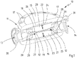
- Fig. 1 a section through a material pressure regulator according to the invention.
- a sectional view of a material pressure regulator 10 according to the invention is shown.
- Its housing 11 contains a pressure chamber 12 in the interior.
- An inlet 13 and an outlet 14 serve to supply or discharge a flowable or fluid medium which can be transported through the pressure chamber 12.
- the medium itself is not shown here.
- the housing 11 is limited in the drawing above and below by a respective lid 15 and 16. These covers 15 and 16 are screwed by means of screws 17 with the rest of the housing 11. Thus, the sealing of the housing 11 can be ensured with respect to the environment.
- the pressure chamber 12 is bounded by two membranes 18 and 19. These membranes 18 and 19 are partially adjacent to each other, namely apart from the region of the inlet 13 and outlet 14 substantially edge side. In the center of the pressure chamber 12, a substantially tubular region for the passage of the medium is formed. This extends from the inlet 13 to the outlet 14. Thus, an almost linear passage through the pressure chamber 12 can take place.
- the two membranes 18 and 19 are contacted by pistons 20 and 21, respectively.
- the pistons 20 and 21 serve to build up a counter-pressure to the pressure of the medium in the interior of the pressure chamber 12.
- the pistons are movably mounted, namely in the direction of the double arrows entered in the drawing for the respective direction of movement 22 or 23 of the pistons 20 and 21. This ensures that the distance of the membranes 18 and 19 and thus the volume of the pressure chamber 12 can be varied , When the pistons 18 and 19 move apart, the volume of the Pressure chamber 12 larger. When the pistons 18 and 19 move toward each other, the volume of the pressure chamber 12 becomes correspondingly smaller.
- the pistons 20 and 21 are each provided with a further pressure membrane 24 or 25.
- the pressure membranes 24 and 25 respectively delimit a pressure chamber 26 and 27 with respect to the respective cover 15 and 16, respectively.
- This pressure chamber 26 and 27 serve to act upon a pressure medium, not shown here, in particular compressed air.
- a back pressure on the piston 20 and 21 are constructed, which acts against the pressure of the medium in the pressure chamber 12.
- Circumferentially surrounding these pressure membranes 24 and 25 are clamped to the housing 11.
- the clamping takes place between the respective cover 15 or 16 and the actual housing 11.
- the membranes 18 and 19 are here also laterally circumferentially clamped on the housing 11.
- the clamping takes place between a membrane holding element 28 or 29, for example in the form of a circular clamping ring, and the actual housing 11.
- the membranes 18, 19, 24, 25 are each held securely and sealingly.
- the piston 20 is surrounded by the membrane 18 and the pressure membrane 24 as a whole.
- the piston 21 with the membrane 19 and the pressure membrane 25.
- This ensures that on the one hand a sealing of the pressure chamber 12 takes place against leakage of the medium.
- the pressure membrane 24 or 25 but also ensures that the print medium can not escape unintentionally.
- the material pressure regulator 10 When used according to the invention, for example in a paint spraying system not shown in detail here, the material pressure regulator 10 is provided, on the one hand, with a supply line of a medium under pressure, in particular a paint or a lacquer. The medium is pumped from a reservoir in the direction of the material pressure regulator 10.
- This supply line can then be fastened to the inlet 13, for example by means of a flange 30.
- the outlet 14 of the material pressure regulator 10 can then be connected in accordance with, for example, by means of a flange 31 with a return for the return of the medium.
- a return conveys the medium not discharged from the nozzles back towards a reservoir. This is how a cycle is formed.
- the material pressure regulator 10 also controls accordingly.
- the pressure in the pressure chamber 12 increases, so that the pistons 20 and 12 are moved against the back pressure to the outside.
- the pressure in the pressure chamber 12 decreases accordingly.
- the pressure chambers 26 and 27 for the two pistons 20 and 21 are typically subjected to the same pressure. This is typically done by a compressed air supply.
- spring action may be provided.
- mechanical springs in particular prestressed springs (compression or tension springs) be used.
- An adjustability of the spring tension for example, the spring travel, ensures adjustability of the back pressure.
- the pressure can be set externally so that optimum pressure conditions are always established, irrespective of the demand from the nozzles of the spray guns or other consumers for the medium.
- the two pistons 20 and 21 and the associated membranes 18, 19, 24, 25 are identical or at least very similar, there is a uniform, in particular symmetrical adjustment to the respective compensation of the back pressure.
- the pressure chamber 12 is enlarged in a symmetrical manner or reduced again.
Landscapes
- Physics & Mathematics (AREA)
- Engineering & Computer Science (AREA)
- Fluid Mechanics (AREA)
- General Physics & Mathematics (AREA)
- Automation & Control Theory (AREA)
- Power Engineering (AREA)
- Control Of Fluid Pressure (AREA)
- Nozzles (AREA)
Applications Claiming Priority (1)
| Application Number | Priority Date | Filing Date | Title |
|---|---|---|---|
| DE102017110430.5A DE102017110430A1 (de) | 2017-05-12 | 2017-05-12 | Materialdruckregler |
Publications (2)
| Publication Number | Publication Date |
|---|---|
| EP3401020A1 true EP3401020A1 (fr) | 2018-11-14 |
| EP3401020B1 EP3401020B1 (fr) | 2020-08-05 |
Family
ID=62148226
Family Applications (1)
| Application Number | Title | Priority Date | Filing Date |
|---|---|---|---|
| EP18171582.2A Active EP3401020B1 (fr) | 2017-05-12 | 2018-05-09 | Régulateur de pression des matériaux |
Country Status (2)
| Country | Link |
|---|---|
| EP (1) | EP3401020B1 (fr) |
| DE (1) | DE102017110430A1 (fr) |
Cited By (1)
| Publication number | Priority date | Publication date | Assignee | Title |
|---|---|---|---|---|
| CN116557599A (zh) * | 2023-04-26 | 2023-08-08 | 新疆水利水电科学研究院 | 流量调节阀 |
Families Citing this family (1)
| Publication number | Priority date | Publication date | Assignee | Title |
|---|---|---|---|---|
| DE102019106965A1 (de) * | 2019-03-19 | 2020-09-24 | Timmer Gmbh | Verfahren zur Regelung des Versorgungsdruckes in einem Umlaufsystem für eine Beschichtungseinrichtung und Umlaufsystem |
Citations (4)
| Publication number | Priority date | Publication date | Assignee | Title |
|---|---|---|---|---|
| DD204979A1 (de) * | 1981-07-24 | 1983-12-14 | Ruhla Uhren Veb K | Membranventil fuer den gesteuerten medienauftrag |
| DE19854620A1 (de) * | 1998-11-26 | 2000-06-15 | Festo Ag & Co | Ventileinrichtung, insbesondere Verstärker |
| DE69817238T2 (de) * | 1997-03-14 | 2004-06-17 | Smc K.K. | Rücksaugventil |
| US20050006617A1 (en) * | 2003-07-11 | 2005-01-13 | Leys John A. | Extended stroke valve and diaphragm |
-
2017
- 2017-05-12 DE DE102017110430.5A patent/DE102017110430A1/de not_active Withdrawn
-
2018
- 2018-05-09 EP EP18171582.2A patent/EP3401020B1/fr active Active
Patent Citations (4)
| Publication number | Priority date | Publication date | Assignee | Title |
|---|---|---|---|---|
| DD204979A1 (de) * | 1981-07-24 | 1983-12-14 | Ruhla Uhren Veb K | Membranventil fuer den gesteuerten medienauftrag |
| DE69817238T2 (de) * | 1997-03-14 | 2004-06-17 | Smc K.K. | Rücksaugventil |
| DE19854620A1 (de) * | 1998-11-26 | 2000-06-15 | Festo Ag & Co | Ventileinrichtung, insbesondere Verstärker |
| US20050006617A1 (en) * | 2003-07-11 | 2005-01-13 | Leys John A. | Extended stroke valve and diaphragm |
Cited By (1)
| Publication number | Priority date | Publication date | Assignee | Title |
|---|---|---|---|---|
| CN116557599A (zh) * | 2023-04-26 | 2023-08-08 | 新疆水利水电科学研究院 | 流量调节阀 |
Also Published As
| Publication number | Publication date |
|---|---|
| DE102017110430A1 (de) | 2018-11-15 |
| EP3401020B1 (fr) | 2020-08-05 |
Similar Documents
| Publication | Publication Date | Title |
|---|---|---|
| DE4310232C2 (de) | Notabschaltventil mit Regulator | |
| DE4139703A1 (de) | Hochdruck-fluidregler | |
| DE3232208C2 (de) | Druckregler | |
| EP0498159A2 (fr) | Régulateur de pression compensé en température | |
| EP3401020B1 (fr) | Régulateur de pression des matériaux | |
| EP1851098B9 (fr) | Cylindre de frein a accumulateur a ressort et de service combine avec dispositif de respiration | |
| DE1148040B (de) | Zweistufiges Druckminderventil fuer Atmungsgeraete | |
| DE2527249C2 (de) | Druckregler für strömende Medien | |
| DE2305687A1 (de) | Druckreguliervorrichtung | |
| DE278689C (fr) | ||
| DE60008176T2 (de) | Vorrichtung zum Ausgleichen von Druckstössen mit einem Druckregelungssystem | |
| EP1780452A2 (fr) | Réducteur de pression | |
| DE2346299A1 (de) | Regelbare strahlpumpe, insbesondere fuer heizungsanlagen | |
| DE29618080U1 (de) | Druckregler | |
| DE2407223C2 (de) | Druckminderer, insbesondere für Hauswasseranlagen | |
| DE3142331A1 (de) | Gedaempftes rueckschlagventil | |
| DE102023136545B4 (de) | Regler ohne Hilfsenergie mit Signalleitungen | |
| DE2359470C3 (de) | Druckminderventil | |
| DE1024903B (de) | Gasdruckregler mit einem von einer belasteten Membran gesteuerten Regelventil | |
| DE3046378A1 (de) | Pneumatischer zweipunktregler | |
| DE2358152C2 (de) | Druckschwankungen im Arbeitsmedium ausgleichendes Membranventil | |
| DE4414189A1 (de) | Druckregler | |
| DE2431442A1 (de) | Druckmittelgesteuertes umsteuerventil | |
| DE2219962A1 (de) | Membranventil zum absperren und/oder regeln eines stroemungsmediums in einer rohrleitung | |
| DE2435877A1 (de) | Regelventil |
Legal Events
| Date | Code | Title | Description |
|---|---|---|---|
| PUAI | Public reference made under article 153(3) epc to a published international application that has entered the european phase |
Free format text: ORIGINAL CODE: 0009012 |
|
| STAA | Information on the status of an ep patent application or granted ep patent |
Free format text: STATUS: THE APPLICATION HAS BEEN PUBLISHED |
|
| AK | Designated contracting states |
Kind code of ref document: A1 Designated state(s): AL AT BE BG CH CY CZ DE DK EE ES FI FR GB GR HR HU IE IS IT LI LT LU LV MC MK MT NL NO PL PT RO RS SE SI SK SM TR |
|
| AX | Request for extension of the european patent |
Extension state: BA ME |
|
| STAA | Information on the status of an ep patent application or granted ep patent |
Free format text: STATUS: REQUEST FOR EXAMINATION WAS MADE |
|
| 17P | Request for examination filed |
Effective date: 20190507 |
|
| RBV | Designated contracting states (corrected) |
Designated state(s): AL AT BE BG CH CY CZ DE DK EE ES FI FR GB GR HR HU IE IS IT LI LT LU LV MC MK MT NL NO PL PT RO RS SE SI SK SM TR |
|
| GRAP | Despatch of communication of intention to grant a patent |
Free format text: ORIGINAL CODE: EPIDOSNIGR1 |
|
| STAA | Information on the status of an ep patent application or granted ep patent |
Free format text: STATUS: GRANT OF PATENT IS INTENDED |
|
| INTG | Intention to grant announced |
Effective date: 20200205 |
|
| GRAS | Grant fee paid |
Free format text: ORIGINAL CODE: EPIDOSNIGR3 |
|
| GRAA | (expected) grant |
Free format text: ORIGINAL CODE: 0009210 |
|
| STAA | Information on the status of an ep patent application or granted ep patent |
Free format text: STATUS: THE PATENT HAS BEEN GRANTED |
|
| AK | Designated contracting states |
Kind code of ref document: B1 Designated state(s): AL AT BE BG CH CY CZ DE DK EE ES FI FR GB GR HR HU IE IS IT LI LT LU LV MC MK MT NL NO PL PT RO RS SE SI SK SM TR |
|
| REG | Reference to a national code |
Ref country code: GB Ref legal event code: FG4D Free format text: NOT ENGLISH |
|
| REG | Reference to a national code |
Ref country code: CH Ref legal event code: EP |
|
| REG | Reference to a national code |
Ref country code: AT Ref legal event code: REF Ref document number: 1297970 Country of ref document: AT Kind code of ref document: T Effective date: 20200815 |
|
| REG | Reference to a national code |
Ref country code: DE Ref legal event code: R096 Ref document number: 502018002067 Country of ref document: DE |
|
| REG | Reference to a national code |
Ref country code: IE Ref legal event code: FG4D Free format text: LANGUAGE OF EP DOCUMENT: GERMAN |
|
| REG | Reference to a national code |
Ref country code: LT Ref legal event code: MG4D |
|
| REG | Reference to a national code |
Ref country code: NL Ref legal event code: MP Effective date: 20200805 |
|
| PG25 | Lapsed in a contracting state [announced via postgrant information from national office to epo] |
Ref country code: HR Free format text: LAPSE BECAUSE OF FAILURE TO SUBMIT A TRANSLATION OF THE DESCRIPTION OR TO PAY THE FEE WITHIN THE PRESCRIBED TIME-LIMIT Effective date: 20200805 Ref country code: GR Free format text: LAPSE BECAUSE OF FAILURE TO SUBMIT A TRANSLATION OF THE DESCRIPTION OR TO PAY THE FEE WITHIN THE PRESCRIBED TIME-LIMIT Effective date: 20201106 Ref country code: NO Free format text: LAPSE BECAUSE OF FAILURE TO SUBMIT A TRANSLATION OF THE DESCRIPTION OR TO PAY THE FEE WITHIN THE PRESCRIBED TIME-LIMIT Effective date: 20201105 Ref country code: PT Free format text: LAPSE BECAUSE OF FAILURE TO SUBMIT A TRANSLATION OF THE DESCRIPTION OR TO PAY THE FEE WITHIN THE PRESCRIBED TIME-LIMIT Effective date: 20201207 Ref country code: FI Free format text: LAPSE BECAUSE OF FAILURE TO SUBMIT A TRANSLATION OF THE DESCRIPTION OR TO PAY THE FEE WITHIN THE PRESCRIBED TIME-LIMIT Effective date: 20200805 Ref country code: SE Free format text: LAPSE BECAUSE OF FAILURE TO SUBMIT A TRANSLATION OF THE DESCRIPTION OR TO PAY THE FEE WITHIN THE PRESCRIBED TIME-LIMIT Effective date: 20200805 Ref country code: ES Free format text: LAPSE BECAUSE OF FAILURE TO SUBMIT A TRANSLATION OF THE DESCRIPTION OR TO PAY THE FEE WITHIN THE PRESCRIBED TIME-LIMIT Effective date: 20200805 Ref country code: LT Free format text: LAPSE BECAUSE OF FAILURE TO SUBMIT A TRANSLATION OF THE DESCRIPTION OR TO PAY THE FEE WITHIN THE PRESCRIBED TIME-LIMIT Effective date: 20200805 Ref country code: BG Free format text: LAPSE BECAUSE OF FAILURE TO SUBMIT A TRANSLATION OF THE DESCRIPTION OR TO PAY THE FEE WITHIN THE PRESCRIBED TIME-LIMIT Effective date: 20201105 |
|
| PG25 | Lapsed in a contracting state [announced via postgrant information from national office to epo] |
Ref country code: LV Free format text: LAPSE BECAUSE OF FAILURE TO SUBMIT A TRANSLATION OF THE DESCRIPTION OR TO PAY THE FEE WITHIN THE PRESCRIBED TIME-LIMIT Effective date: 20200805 Ref country code: PL Free format text: LAPSE BECAUSE OF FAILURE TO SUBMIT A TRANSLATION OF THE DESCRIPTION OR TO PAY THE FEE WITHIN THE PRESCRIBED TIME-LIMIT Effective date: 20200805 Ref country code: NL Free format text: LAPSE BECAUSE OF FAILURE TO SUBMIT A TRANSLATION OF THE DESCRIPTION OR TO PAY THE FEE WITHIN THE PRESCRIBED TIME-LIMIT Effective date: 20200805 Ref country code: RS Free format text: LAPSE BECAUSE OF FAILURE TO SUBMIT A TRANSLATION OF THE DESCRIPTION OR TO PAY THE FEE WITHIN THE PRESCRIBED TIME-LIMIT Effective date: 20200805 Ref country code: IS Free format text: LAPSE BECAUSE OF FAILURE TO SUBMIT A TRANSLATION OF THE DESCRIPTION OR TO PAY THE FEE WITHIN THE PRESCRIBED TIME-LIMIT Effective date: 20201205 |
|
| PG25 | Lapsed in a contracting state [announced via postgrant information from national office to epo] |
Ref country code: SM Free format text: LAPSE BECAUSE OF FAILURE TO SUBMIT A TRANSLATION OF THE DESCRIPTION OR TO PAY THE FEE WITHIN THE PRESCRIBED TIME-LIMIT Effective date: 20200805 Ref country code: EE Free format text: LAPSE BECAUSE OF FAILURE TO SUBMIT A TRANSLATION OF THE DESCRIPTION OR TO PAY THE FEE WITHIN THE PRESCRIBED TIME-LIMIT Effective date: 20200805 Ref country code: RO Free format text: LAPSE BECAUSE OF FAILURE TO SUBMIT A TRANSLATION OF THE DESCRIPTION OR TO PAY THE FEE WITHIN THE PRESCRIBED TIME-LIMIT Effective date: 20200805 Ref country code: DK Free format text: LAPSE BECAUSE OF FAILURE TO SUBMIT A TRANSLATION OF THE DESCRIPTION OR TO PAY THE FEE WITHIN THE PRESCRIBED TIME-LIMIT Effective date: 20200805 Ref country code: CZ Free format text: LAPSE BECAUSE OF FAILURE TO SUBMIT A TRANSLATION OF THE DESCRIPTION OR TO PAY THE FEE WITHIN THE PRESCRIBED TIME-LIMIT Effective date: 20200805 |
|
| REG | Reference to a national code |
Ref country code: DE Ref legal event code: R097 Ref document number: 502018002067 Country of ref document: DE |
|
| PG25 | Lapsed in a contracting state [announced via postgrant information from national office to epo] |
Ref country code: AL Free format text: LAPSE BECAUSE OF FAILURE TO SUBMIT A TRANSLATION OF THE DESCRIPTION OR TO PAY THE FEE WITHIN THE PRESCRIBED TIME-LIMIT Effective date: 20200805 |
|
| PLBE | No opposition filed within time limit |
Free format text: ORIGINAL CODE: 0009261 |
|
| STAA | Information on the status of an ep patent application or granted ep patent |
Free format text: STATUS: NO OPPOSITION FILED WITHIN TIME LIMIT |
|
| PG25 | Lapsed in a contracting state [announced via postgrant information from national office to epo] |
Ref country code: SK Free format text: LAPSE BECAUSE OF FAILURE TO SUBMIT A TRANSLATION OF THE DESCRIPTION OR TO PAY THE FEE WITHIN THE PRESCRIBED TIME-LIMIT Effective date: 20200805 |
|
| 26N | No opposition filed |
Effective date: 20210507 |
|
| PG25 | Lapsed in a contracting state [announced via postgrant information from national office to epo] |
Ref country code: IT Free format text: LAPSE BECAUSE OF FAILURE TO SUBMIT A TRANSLATION OF THE DESCRIPTION OR TO PAY THE FEE WITHIN THE PRESCRIBED TIME-LIMIT Effective date: 20200805 |
|
| PG25 | Lapsed in a contracting state [announced via postgrant information from national office to epo] |
Ref country code: SI Free format text: LAPSE BECAUSE OF FAILURE TO SUBMIT A TRANSLATION OF THE DESCRIPTION OR TO PAY THE FEE WITHIN THE PRESCRIBED TIME-LIMIT Effective date: 20200805 |
|
| REG | Reference to a national code |
Ref country code: CH Ref legal event code: PL |
|
| PG25 | Lapsed in a contracting state [announced via postgrant information from national office to epo] |
Ref country code: LU Free format text: LAPSE BECAUSE OF NON-PAYMENT OF DUE FEES Effective date: 20210509 Ref country code: MC Free format text: LAPSE BECAUSE OF FAILURE TO SUBMIT A TRANSLATION OF THE DESCRIPTION OR TO PAY THE FEE WITHIN THE PRESCRIBED TIME-LIMIT Effective date: 20200805 Ref country code: LI Free format text: LAPSE BECAUSE OF NON-PAYMENT OF DUE FEES Effective date: 20210531 Ref country code: CH Free format text: LAPSE BECAUSE OF NON-PAYMENT OF DUE FEES Effective date: 20210531 |
|
| REG | Reference to a national code |
Ref country code: BE Ref legal event code: MM Effective date: 20210531 |
|
| PG25 | Lapsed in a contracting state [announced via postgrant information from national office to epo] |
Ref country code: IE Free format text: LAPSE BECAUSE OF NON-PAYMENT OF DUE FEES Effective date: 20210509 |
|
| PG25 | Lapsed in a contracting state [announced via postgrant information from national office to epo] |
Ref country code: BE Free format text: LAPSE BECAUSE OF NON-PAYMENT OF DUE FEES Effective date: 20210531 |
|
| PG25 | Lapsed in a contracting state [announced via postgrant information from national office to epo] |
Ref country code: CY Free format text: LAPSE BECAUSE OF FAILURE TO SUBMIT A TRANSLATION OF THE DESCRIPTION OR TO PAY THE FEE WITHIN THE PRESCRIBED TIME-LIMIT Effective date: 20200805 |
|
| PG25 | Lapsed in a contracting state [announced via postgrant information from national office to epo] |
Ref country code: HU Free format text: LAPSE BECAUSE OF FAILURE TO SUBMIT A TRANSLATION OF THE DESCRIPTION OR TO PAY THE FEE WITHIN THE PRESCRIBED TIME-LIMIT; INVALID AB INITIO Effective date: 20180509 |
|
| PG25 | Lapsed in a contracting state [announced via postgrant information from national office to epo] |
Ref country code: MK Free format text: LAPSE BECAUSE OF FAILURE TO SUBMIT A TRANSLATION OF THE DESCRIPTION OR TO PAY THE FEE WITHIN THE PRESCRIBED TIME-LIMIT Effective date: 20200805 |
|
| REG | Reference to a national code |
Ref country code: AT Ref legal event code: MM01 Ref document number: 1297970 Country of ref document: AT Kind code of ref document: T Effective date: 20230509 |
|
| PG25 | Lapsed in a contracting state [announced via postgrant information from national office to epo] |
Ref country code: AT Free format text: LAPSE BECAUSE OF NON-PAYMENT OF DUE FEES Effective date: 20230509 |
|
| PG25 | Lapsed in a contracting state [announced via postgrant information from national office to epo] |
Ref country code: AT Free format text: LAPSE BECAUSE OF NON-PAYMENT OF DUE FEES Effective date: 20230509 |
|
| PG25 | Lapsed in a contracting state [announced via postgrant information from national office to epo] |
Ref country code: MT Free format text: LAPSE BECAUSE OF FAILURE TO SUBMIT A TRANSLATION OF THE DESCRIPTION OR TO PAY THE FEE WITHIN THE PRESCRIBED TIME-LIMIT Effective date: 20200805 |
|
| PGFP | Annual fee paid to national office [announced via postgrant information from national office to epo] |
Ref country code: DE Payment date: 20250401 Year of fee payment: 8 |
|
| PGFP | Annual fee paid to national office [announced via postgrant information from national office to epo] |
Ref country code: GB Payment date: 20250410 Year of fee payment: 8 |
|
| PGFP | Annual fee paid to national office [announced via postgrant information from national office to epo] |
Ref country code: FR Payment date: 20250409 Year of fee payment: 8 |
|
| PG25 | Lapsed in a contracting state [announced via postgrant information from national office to epo] |
Ref country code: TR Free format text: LAPSE BECAUSE OF FAILURE TO SUBMIT A TRANSLATION OF THE DESCRIPTION OR TO PAY THE FEE WITHIN THE PRESCRIBED TIME-LIMIT Effective date: 20200805 |
|
| PGFP | Annual fee paid to national office [announced via postgrant information from national office to epo] |
Ref country code: AT Payment date: 20260410 Year of fee payment: 5 |