EP3403522B1 - Jewelry article and process for making said jewelry article - Google Patents
Jewelry article and process for making said jewelry article Download PDFInfo
- Publication number
- EP3403522B1 EP3403522B1 EP18172417.0A EP18172417A EP3403522B1 EP 3403522 B1 EP3403522 B1 EP 3403522B1 EP 18172417 A EP18172417 A EP 18172417A EP 3403522 B1 EP3403522 B1 EP 3403522B1
- Authority
- EP
- European Patent Office
- Prior art keywords
- jewelry article
- common base
- connection element
- jewelry
- stems
- Prior art date
- Legal status (The legal status is an assumption and is not a legal conclusion. Google has not performed a legal analysis and makes no representation as to the accuracy of the status listed.)
- Active
Links
Images





Classifications
-
- A—HUMAN NECESSITIES
- A44—HABERDASHERY; JEWELLERY
- A44C—PERSONAL ADORNMENTS, e.g. JEWELLERY; COINS
- A44C27/00—Making jewellery or other personal adornments
-
- A—HUMAN NECESSITIES
- A44—HABERDASHERY; JEWELLERY
- A44C—PERSONAL ADORNMENTS, e.g. JEWELLERY; COINS
- A44C11/00—Watch chains; Ornamental chains
-
- A—HUMAN NECESSITIES
- A44—HABERDASHERY; JEWELLERY
- A44C—PERSONAL ADORNMENTS, e.g. JEWELLERY; COINS
- A44C27/00—Making jewellery or other personal adornments
- A44C27/001—Materials for manufacturing jewellery
- A44C27/002—Metallic materials
-
- A—HUMAN NECESSITIES
- A44—HABERDASHERY; JEWELLERY
- A44C—PERSONAL ADORNMENTS, e.g. JEWELLERY; COINS
- A44C27/00—Making jewellery or other personal adornments
- A44C27/001—Materials for manufacturing jewellery
- A44C27/002—Metallic materials
- A44C27/003—Metallic alloys
-
- A—HUMAN NECESSITIES
- A44—HABERDASHERY; JEWELLERY
- A44C—PERSONAL ADORNMENTS, e.g. JEWELLERY; COINS
- A44C5/00—Bracelets; Wrist-watch straps; Fastenings for bracelets or wrist-watch straps
- A44C5/0053—Flexible straps
- A44C5/0061—Flexible straps essentially made from metal
-
- A—HUMAN NECESSITIES
- A44—HABERDASHERY; JEWELLERY
- A44C—PERSONAL ADORNMENTS, e.g. JEWELLERY; COINS
- A44C5/00—Bracelets; Wrist-watch straps; Fastenings for bracelets or wrist-watch straps
- A44C5/02—Link constructions
- A44C5/10—Link constructions not extensible
- A44C5/102—Link constructions not extensible with links made of one piece with integral connecting means
-
- B—PERFORMING OPERATIONS; TRANSPORTING
- B22—CASTING; POWDER METALLURGY
- B22F—WORKING METALLIC POWDER; MANUFACTURE OF ARTICLES FROM METALLIC POWDER; MAKING METALLIC POWDER; APPARATUS OR DEVICES SPECIALLY ADAPTED FOR METALLIC POWDER
- B22F10/00—Additive manufacturing of workpieces or articles from metallic powder
- B22F10/20—Direct sintering or melting
- B22F10/28—Powder bed fusion, e.g. selective laser melting [SLM] or electron beam melting [EBM]
-
- B—PERFORMING OPERATIONS; TRANSPORTING
- B22—CASTING; POWDER METALLURGY
- B22F—WORKING METALLIC POWDER; MANUFACTURE OF ARTICLES FROM METALLIC POWDER; MAKING METALLIC POWDER; APPARATUS OR DEVICES SPECIALLY ADAPTED FOR METALLIC POWDER
- B22F10/00—Additive manufacturing of workpieces or articles from metallic powder
- B22F10/40—Structures for supporting workpieces or articles during manufacture and removed afterwards
- B22F10/47—Structures for supporting workpieces or articles during manufacture and removed afterwards characterised by structural features
-
- B—PERFORMING OPERATIONS; TRANSPORTING
- B33—ADDITIVE MANUFACTURING TECHNOLOGY
- B33Y—ADDITIVE MANUFACTURING, i.e. MANUFACTURING OF THREE-DIMENSIONAL [3D] OBJECTS BY ADDITIVE DEPOSITION, ADDITIVE AGGLOMERATION OR ADDITIVE LAYERING, e.g. BY 3D PRINTING, STEREOLITHOGRAPHY OR SELECTIVE LASER SINTERING
- B33Y10/00—Processes of additive manufacturing
-
- B—PERFORMING OPERATIONS; TRANSPORTING
- B33—ADDITIVE MANUFACTURING TECHNOLOGY
- B33Y—ADDITIVE MANUFACTURING, i.e. MANUFACTURING OF THREE-DIMENSIONAL [3D] OBJECTS BY ADDITIVE DEPOSITION, ADDITIVE AGGLOMERATION OR ADDITIVE LAYERING, e.g. BY 3D PRINTING, STEREOLITHOGRAPHY OR SELECTIVE LASER SINTERING
- B33Y80/00—Products made by additive manufacturing
-
- Y—GENERAL TAGGING OF NEW TECHNOLOGICAL DEVELOPMENTS; GENERAL TAGGING OF CROSS-SECTIONAL TECHNOLOGIES SPANNING OVER SEVERAL SECTIONS OF THE IPC; TECHNICAL SUBJECTS COVERED BY FORMER USPC CROSS-REFERENCE ART COLLECTIONS [XRACs] AND DIGESTS
- Y02—TECHNOLOGIES OR APPLICATIONS FOR MITIGATION OR ADAPTATION AGAINST CLIMATE CHANGE
- Y02P—CLIMATE CHANGE MITIGATION TECHNOLOGIES IN THE PRODUCTION OR PROCESSING OF GOODS
- Y02P10/00—Technologies related to metal processing
- Y02P10/25—Process efficiency
Definitions
- the present invention refers to a jewelry article and to a process for making said jewelry article, according to the preamble of the respective independent claims.
- the present jewelry article is intended to entirely or partly constitute ornamental products, such as bracelets, necklaces and similar articles made of precious metal such as gold or platinum or alloys thereof.
- the process for making the aforesaid article is therefore intended to be employed in the jewelry article manufacturing industry and in particular gold/jewelry-making industry.
- jewelry articles comprising at least one mesh made of precious or semi-precious material, formed by a weave of wires or cords of precious material interwoven with each other, in a manner analogous to that of a normal knitwear fabric.
- a further drawback lies in the fact that the weave of the precious metal wires in the weaving of a mesh does not allow optimizing some mechanical properties, such as flexibility, if not to the detriment of other properties such as surface continuity, so that only by leaving suitable spaces between the wires is it possible to obtain the desired flexibility.
- Ornamental articles made of precious metal are known that are obtained by coupling together single side-by-side elements, by mechanically coupling them together, sequentially linking them for example on a surface or connecting them through the use of third elements such as pins in the formation of watch straps.
- a further process for making jewelry articles which provides for the use of the metallurgic technique of lost-wax casting, in particular a process for micro-casting, which consists of preparing a wax model, having the same shape as the jewel to be produced.
- a process for micro-casting which consists of preparing a wax model, having the same shape as the jewel to be produced.
- a layer of thermosetting resins and ceramic granules is set, which together form a very strong mold outside the wax.
- the wax is dissolved and removed from the mold, for example by means of heating in an oven.
- the precious metal which will constitute the jewelry article is cast inside the mold, forming the jewel, which once cooled is extracted from the mold and polished.
- Such process allows producing jewelry articles of any shape and size.
- One drawback of jewelry articles obtained by means of such process consists of the high production cost, also due to a high consumption of tertiary materials for making the mold, which, once the making of the jewelry article is completed, become a waste product to be disposed of.
- a further drawback of the jewelry articles obtained by means of such process consists of the fact that they are not elastic, rendering impossible the production of precious-material meshes provided with the desired flexibility.
- such ring-like meshes are made by means of the linking of each precious-material ring (e.g. gold or silver) with three other corresponding precious-material rings, each of which connected to another three corresponding rings.
- each precious-material ring e.g. gold or silver
- the main drawback lies in the fact that the process for the making thereof requires a step for welding each ring once inserted within the corresponding adjacent ring. Such welding requires considerable precision by the operator in order to avoid forming large, unaesthetic welding points and in order to obtain a mesh of exceptional/high-value workmanship.
- a further drawback lies in the fact that the rings which compose the mesh obtained by means of the aforesaid process superficially have the mark of the welding for the linking thereof, conferring a blemish to the entire mesh thus obtained.
- a further drawback lies in the fact that the possible weave variation is very limited, in particular limited to the selection of diameter thickness of the central hole of the rings which compose the mesh, and therefore it is not possible to make really attractive and/or fashionable forms.
- a step is provided for exporting the drawing obtained in the preceding design step in order to implement it in a 3D printer, which automatically forms the object by means of successive superimposition of layers of plastic material with low melting point, such as polyethylene.
- gypsum-based plaster which is a refractory material and has melting point higher than 1000°C.
- a firing step in which the casting tank is heated until the plastic material which constitutes the model of the jewelry article to be formed is melted, and then such plastic material is removed, freeing a mold with shape corresponding to the jewelry article to be formed.
- a casting step in which a precious or semi-precious molten metal material is cast within the casting tank.
- molten metal penetrates within the gypsum-based plaster, into the grooves of the mold free of the previously-removed plastic material, taking the shape thereof.
- the plaster is removed, obtaining the desired jewelry article.
- a first drawback lies in the fact that the need to cast the molten metal within the mold requires that the latter does not have capillarity or narrowing. Consequently, with the method described up to now, it is not possible to make jewelry articles provided with extremely complex structure and small size. Therefore, with such method it is not possible to make a jewelry article comprising a mesh of precious material.
- a further drawback lies in the fact that the process is long, difficult and produces a high quantity of waste materials for each jewelry article produced.
- Document CN 106235540 describes an example of a jewelry article equipped with connecting elements connected together to form a leaf-like shaped jewel which extends on a plane of arrangement.
- connection elements are movable with respect to one another along an axis of movement perpendicular to the plane of arrangement of the jewelry article. Such mutual movement of the connection elements leads to an unsatisfactory visual feed-back of the jewelry article, since it appears with an irregular visible surface.
- the main object of the present invention is that of eliminating the drawbacks of the abovementioned prior art, by providing a leaf-like jewelry article which can take on, on at least one surface thereof, very different shapes even while maintaining optimal mechanical strength characteristics, or also flexibility characteristics.
- a further object of the present invention is to provide a jewelry article which is simultaneously flexible and strong.
- a further object of the present invention is to provide a jewelry article which completely lacks blemishes such as welding points.
- a further object of the present invention is to provide a process for making jewelry articles which allows making jewelry articles with very complex shapes.
- a further object of the present invention is to provide a process for making jewelry articles which allows an attainment thereof with very high precision, and in an automated manner.
- a further object of the present invention is to provide a process for making jewelry articles which is ecologically sustainable and which substantially does not produce polluting waste.
- a further object of the present invention is to provide a process for making jewelry articles which is inexpensive, versatile and easy to carry out.
- a further object of the present invention is to provide a jewelry article which is inexpensive, mechanically strong, light and extremely flexible.
- reference number 1 overall indicates a jewelry article according to the present invention, which is advantageously obtainable by means of the process, object of the present invention.
- the leaf-like jewelry article, object of the present invention comprises a plurality of connection elements 2, linked with each other along a lying plane X, in accordance with a first embodiment illustrated in figure 1 , with a third embodiment illustrated in figure 5 and with a third embodiment illustrated in figure 8 .
- connection elements 2 which form the jewelry article 1, object of the present invention are made of precious metal, such as gold or platinum.
- connection elements 2 are linked together and form a flexible mesh, wearable by a user for ornamental purposes.
- each connection element 2 comprises at least one first common base 11 defining a first visible face 5 of the jewelry article 1 and at least one first internal face.
- connection element 2 also comprises at least one second common base 12 defining a second face 6 of the jewelry article 1 and at least three stems 3, 7, 9 which connect the first internal face of the first common base 11 to the second common base 12 generating, between pairs of the stems 3, 7, 9, at least three corresponding passage openings 4, 8, 10 linked with three stems 3, 7, 9 of three corresponding contiguous connection elements 2.
- Each stem 3, 7, 9 is extended with a progression substantially helically wound around an axis Z orthogonal to the lying plane X, defining an intermediate elbow-like section 20, which projects outside the bulk of the first and the second common base 11, 12 on the lying plane X, has concavity directed towards the interior of the connection element 2 and encloses the intermediate elbow-like section 20 of a contiguous connection element 2.
- connection element 2 is firmly constrained to at least three connection elements 2 contiguous thereto, by means of the linking of the stems 3, 7, 9 within the corresponding passage openings 4, 8, 10, making a two-dimensional solid and flexible chain.
- the stems 3, 7, 9 of each connection element 2 are engaged with corresponding stems 3, 7, 9 of contiguous connection elements 2 by means of linking.
- the intermediate elbow-like section 20 of the stems 3, 7, 9 of each connection element 2 encloses and constrains the intermediate elbow-like section 20 of the corresponding stem 3, 7, 9 of a contiguous connection element 2.
- each first common base 11 of each connection element 2 has a greater size on the lying plane X of the jewelry article 1 than the size on such lying plane X of the second common base 12.
- first common base 11 of each connection element 2 which defines the first visible face 5 of the leaf-like jewelry article 1, object of the present invention, is adjacent and side-by-side the first common base 11 of the contiguous connection elements 2, and the second common base 12 of each connection element 2 is spaced from the second common base 12 of the contiguous connection elements, allowing a greater mobility of the jewelry article 1.
- the second common base 12 of each connection element 2 defines the aforesaid second face 6, which preferably is not visible when the leaf-like jewelry article 1 is worn by the user. More clearly, the second common base 12 is substantially in contact with the skin (or with the clothes) of the user, and therefore is not visible from the outside.
- the second common base 12 of each connection element 2 defines a second internal face facing the first internal face of the first common base.
- the user sets the second common bases 12 of the connection elements 2 on the desired point.
- Such second common bases 12 being spaced from each other, allow a relative rotation of the connection elements 2, i.e. by means of a sliding of the stems 3, 7, 9, in particular a relative rotation of the intermediate elbow-like sections 20 of the stems 3, 7, 9 that enclose each other.
- the article 1 is set on the desired point, by lying on the second common bases 12.
- the first common bases 11 are adjacent to each other and even after the relative rotation of the connection elements 2 remain substantially side-by-side, forming an ornamental surface that is pleasing to the sight, since it appears to be continuous in the eyes of an observer.
- the first visible face 5 defined by the first common base 11 can have any shape and any configuration, in order to provide the jewelry article 1 with the desired aesthetic character.
- each first visible face 5 of the first common base 11 of each connection element 2 is provided with substantially quadrangular form, in particular pyramidal with square base.
- each first visible face 5 of the first common base 11 is provided with a curved shape, which is transversely inserted at the ends thereof below two corresponding visible faces 6 of curved form of two adjacent connection elements 2, in order to confer a weave form to the article 1, simulating a ribbon weaving.
- each first visible face 5 of the first common base 11 is provided with a triangular-plate shape.
- each connection element 2 comprises a first tooth 13 fixed to at least one of the at least three stems 3, 7, 9, adapted to support a corresponding stem 3, 7, 9 of a contiguous connection element 2.
- the second common base 12 substantially has polygonal or circular plate form, and the stems 3, 7, 9 are fixed on the second internal face thereof.
- the second common base 12 has annular form, e.g. circular (or toroidal) or polygonal.
- each connection element 2 comprises at least three teeth 13, 14, 15 fixed at the intermediate elbow-like section 20 of one of the corresponding at least three stems 3, 7, 9 and substantially extended towards the interior of the connection element 2 to which they are fixed.
- Such teeth 13, 14, 15 are adapted to support the intermediate elbow-like section of the stem 3, 7, 9 of the contiguous connection element 2 - with which the stem 3, 7, 9 (to which such teeth are fixed) is linked.
- the connection elements 2 remain substantially aligned along the lying plane X, since the teeth 13, 14, 15 do not allow a relative sliding of the connection elements 2 themselves along an axis transverse to the lying plane X.
- each connection element 2 of the leaf-like jewelry article 1, object of the present invention comprises at least four stems 3, 7, 9, 16 which connect the first internal face of the first common base 11 to the second common base 12 generating, between pairs of such stems 3, 7, 9, 16, at least four corresponding passage openings 4, 8, 10, 17 linked with four stems 3, 7, 9, 16 of four corresponding contiguous connection elements 2.
- each connection element 2 comprises four teeth 13, 14, 15, 18, each fixed to a corresponding stem of the four stems 3, 7, 9, 16, at the elbow-like section 20 of the latter.
- each connection element 2 can comprise more than four stems 3, 7, 9, 16, for example it can comprise six stems connected to six other respective stems of six separate and contiguous connection elements 2.
- the first common base has substantially hexagonal shape and the first visible face 5 appreciable by the user substantially has honeycomb shape.
- each connection element 2 comprises at least one first support column 19 fixed on one side to the first internal face of the first common base 11 and on the other side to the second internal face of the second common base 12.
- each connection element 2 comprises a first support column 19 extended along a main extension axis Y of the connection element 2 itself, parallel to the transverse axis Z and substantially transverse with respect to the lying plane X of the jewelry article 1.
- the first support column 19 is therefore placed substantially centrally with respect to the connection element 2 to connect the first and the second common bases 11, 12.
- the stems 3, 7, 9 are arranged on a circumference around such first support column 19.
- the stems 3, 7, 9 of each connection element 2 are all provided with the same shape with helically-wound progression and are symmetrically positioned around the main extension axis Y of the connection element 2 substantially orthogonal to the lying plane X.
- each stem 3, 7, 9 of each connection element 2 defines an angle ⁇ at the ends thereof fixed to the first common base 11 comprised between 20° and 70°, and in particular comprised between 30° and 60°.
- Such angle ⁇ remains defined between each stem 3, 7, 9 and the second common base 12 of each connection element 2 and coincides with the initial angle of the shape helically-wound around the orthogonal axis Z.
- Also forming the object of the present invention is a process for making a jewelry article, in particular of the type described up to now and regarding which, for the sake of simplicity, the previously-indicated reference numbers will be maintained.
- the process for making a jewelry article 1, object of the present invention initially comprises a step for preparing a three-dimensional drawing file of the desired jewelry article 1.
- the step for preparing the file drawing initially provides for a step for designing the desired jewelry article and then its transposition into a three-dimensional drawing file, e.g. by means of a first 3D CAD (Computer-Aided Drafting) software, such as AutoCAD® and the like.
- a first 3D CAD Computer-Aided Drafting
- the step for preparing the three-dimensional drawing provides for providing the jewelry article 1 with a plurality of second support columns fixed to the second common base 12.
- Such second support columns are preferably provided with diameter of several microns, in order to make them easy to remove during a removal step, preferably provided for by the process, object of the present invention, and described more in detail hereinbelow.
- the plurality of second support columns is intended to support the jewelry article 1 during the welding steps provided for by the process, also described in more detail hereinbelow.
- the three-dimensional drawing file is saved in a memory of an electronic calculator, e.g. in "3DM" format.
- the first CAD software converts the drawing from the "3DM” format to a "STL" (STereo Lithography interface format) format, which discretizes the three-dimensional drawing into triangles and tetrahedrons, in order to facilitate the electronic calculator for the subsequent operating steps provided for by the process, object of the present invention.
- STL STereo Lithography interface format
- the process for making a jewelry article 1 also provides for a step for defining a plurality of sections 21 of the drawing by means of the intersection of a plurality of dissection planes parallel to the lying plane X with the three-dimensional drawing of the jewelry article 1.
- the distance between two adjacent sections 21 is comprised between 0.005 mm and 0.05 mm and in particular is comprised between 0.01 mm and 0.03 mm.
- Such step for defining the sections 21 is normally attained by means of a second CAD or CAM (Computer-Aided Manufacturing) software which preferably imports the file of the three-dimensional drawing into "STL" format and intersects it with a plurality of surfaces substantially parallel to the lying plane X of the jewelry article 1.
- CAD or CAM Computer-Aided Manufacturing
- the operator inserts parameters regarding the distance between the aforesaid parallel surfaces, based on the type of material with which the jewelry article 1 will be made and based on the type of laser used, as described in detail hereinbelow.
- the process also provides for a step for arranging a welding path 22 within the borders of the sections 21 of the jewelry article 1 and a step for importing the sections 21 of the three-dimensional drawing into a 3D laser printer.
- the welding path 22 is entirely contained within the borders of the sections 21 defined during the aforesaid definition step.
- the welding path 22 arranged within the borders of the sections 21 comprises a plurality of curves and segments, which describe the points at which a laser beam will pass, in a welding step described in detail hereinbelow.
- the process also provides for the step for welding a powder of precious metals by means of a laser beam of the 3D laser printer along the welding path arranged during the aforesaid arrangement step.
- the 3D printer is advantageously of DMLS (Direct Metal Laser Sintering) type, in a manner per se known to the man skilled in the art.
- the 3D printer comprises a work surface made of metal material on which the precious-metal powder is cyclically set by means of a knife made of rubbery material, in successive layers with thickness preferably equal to the distance between two adjacent sections 21, and thus with thickness comprised between 0.005 mm and 0.05 mm, and in particular is comprised between 0.01 mm and 0.03 mm.
- the laser of the 3D printer is preferably of the type in optical fiber and operating under pulses conditions.
- the welding step is carried out at each section of the three-dimensional drawing of the jewelry article 1, starting from the section at one of the first and second common bases 11, 12 up to the other of the common bases 12, 11 of the jewelry article 1.
- such welding step is carried out for each section of the three-dimensional drawing of the jewelry article 1, starting from the section at the second common base 12 up to the section at the first common base 11 of the jewelry article 1.
- the welding step attains the aforesaid plurality of second support columns, substantially vertical and anchored to the work surface made of metal material.
- Such second support columns are adapted to support the jewelry article during its attainment and in particular during all the welding steps which are repeated for each section.
- the laser beam hits the precious-metal powder at the welding path arranged during the arrangement step and imported into the 3D printer during the step for importing the sections of the three-dimensional drawing of the jewelry article 1.
- the powder made of precious metals hit by the laser beam is heated and quickly reaches the melting point, solidifying at the sections, forming the jewelry article one layer at a time. Indeed, following the melting of a powder layer along the path, the knife transports a new layer of precious-material powder and the 3D printer automatically drives the laser beam to be moved along the path arranged in the subsequent section of the jewelry article.
- connection elements 2 are linked together along the lying plane X at the end of the welding steps.
- the welding step provides that the segments and the curves that constitute the welding path 22 are placed at different distances based on the metals that constitute the precious-metal powder and also provides that the speed with which the laser beam travels and the power with which the laser beam hits the welding path 22 vary based on the aforesaid desired density and based on the metals that constitute the precious-metal powder.
- the segments and the curves that constitute the welding path 22 are placed at an average distance between adjacent segments and/or lines comprised between 0.02 mm and 0.08 mm.
- the average distance between adjacent segments and/or lines of the welding path 22 is comprised between 0.02 mm and 0.05 mm.
- the speed with which the laser beam travels along the welding path 22 during each welding step is preferably comprised between 250 and 1300 mm/s.
- the speed with which the laser beam travels along the welding path 22 is comprised between 300 and 600 mm/s.
- the power of the laser beam during each welding step is preferably comprised between 80W and 130W.
- the power of the laser beam is comprised between 95W and 125W.
- the optimal density for the aforesaid precious metals i.e. gold and/or platinum, is therefore achieved by means of a laser beam provided with the aforesaid travel speeds along the welding path 22 and with the aforesaid power.
- the metal cooled and hardened after the welding steps is provided with an internal porosity comprised between 0.1% and 0.3%, which is considered very low by the man skilled in the art.
- the method provides for a step for removing the excess precious-metal powder, e.g. manually by means of a brush, so as to recover it in order to be able to use it in making a new jewelry article 1.
- the process, object of the present invention also advantageously comprises a step of removing the second support columns made during the casting step, which are easily removable since they are very thin.
- the second support columns are made at the second face 6 defined by the second common base 12, which is intended to lie on the skin of the user. Therefore, even if imperfections appear following the removal step, this would not negatively affect the aesthetic result of the jewelry article achieved by means of the process, object of the present invention.
- the process also comprises a step of polishing the jewelry article 1 at the first common base 11 at its first visible face 5, in order to make the surface intended to be appreciated by users shiny and pleasing to the eye.
- the polishing step can be attained, in a manner per se known to the man skilled in the art, by means of the surface diamond-finishing technique, i.e. by means of a diamond disc susceptible of being driven via an electronic control unit and with the numerical control method.
- the electronic control unit drives an articulatable arm carrying, mounted thereon, a diamond disc at an end thereof, which is free to rotate, sliding on the first visible face 5 of the leaf-like jewelry article 1.
- the polishing step can be attained by means of sandpapering, per se known the man skilled in the art, and obtained by means of the manual positioning by an operator on an abrasive strip rotated by an electric motor, in order to polish the first visible face 5 by means of abrasion.
- the polishing step can also be advantageously made at the second face 6 defined by the second common base 12, in order to also make such second face 6 shiny and pleasing to view, such second face 6 being visible when the jewelry article is not worn by the user.
- the laser beam is driven to lower the power and/or increase the travel speed along the welding path 22 during the formation of the first visible face 5 and of the second face 6, in order to lower the density in proximity thereto, rendering the material more malleable and therefore more easily polishable during the polishing step.
- the method otherwise provides for increasing the travel speed of the laser beam along the welding path 22 in order to decrease the energy deposited along such welding path 22 and make the casting of the metal occur at lower temperatures, and thus forming a metal with lower density with respect to the optimal density.
- the first visible face 5 and the second face 6 are provided with lower density than the density with which the first common base 11 and the second common base 12 are provided, in order to more easily and quickly polish the precious metal that constitutes the jewelry article 1.
- the jewelry article, object of the present invention appears quite aesthetically appreciable and has considerable lightness and high mechanical elasticity.
- the finding thus conceived therefore attains the pre-established objects.
- the jewelry article 1, object of the present invention is mechanically strong, light and extremely flexible.
- the jewelry article 1, object of the present invention completely lacks blemishes, such as welding points.
- the process, object of the present invention allows making jewelry articles 1 with very complex shapes.
- the process for making jewelry articles, object of the present invention allows an attainment thereof with extremely high precision and in an automated manner.
Landscapes
- Engineering & Computer Science (AREA)
- Manufacturing & Machinery (AREA)
- Chemical & Material Sciences (AREA)
- Materials Engineering (AREA)
- Physics & Mathematics (AREA)
- Plasma & Fusion (AREA)
- Adornments (AREA)
Description
- The present invention refers to a jewelry article and to a process for making said jewelry article, according to the preamble of the respective independent claims.
- The present jewelry article is intended to entirely or partly constitute ornamental products, such as bracelets, necklaces and similar articles made of precious metal such as gold or platinum or alloys thereof.
- The process for making the aforesaid article is therefore intended to be employed in the jewelry article manufacturing industry and in particular gold/jewelry-making industry.
- For some time, jewelry articles have been known comprising at least one mesh made of precious or semi-precious material, formed by a weave of wires or cords of precious material interwoven with each other, in a manner analogous to that of a normal knitwear fabric.
- The production of such jewelry articles with meshes made of interwoven precious-material wires involves numerous limitations regarding the structural and morphological characteristics of the final articles that can be obtained.
- The main drawback of these articles of known type therefore lies in the fact that the weaving of the wires required for forming the precious-wire mesh limits the possibilities of varying the final outward appearance of the articles.
- Indeed, even varying the dimensions of the wires and the shape of the weft that is woven with the precious metal wires, the outward appearance of the obtained ornamental articles is excessively limited.
- A further drawback lies in the fact that the weave of the precious metal wires in the weaving of a mesh does not allow optimizing some mechanical properties, such as flexibility, if not to the detriment of other properties such as surface continuity, so that only by leaving suitable spaces between the wires is it possible to obtain the desired flexibility.
- Ornamental articles made of precious metal are known that are obtained by coupling together single side-by-side elements, by mechanically coupling them together, sequentially linking them for example on a surface or connecting them through the use of third elements such as pins in the formation of watch straps.
- Such articles are very complex to make and have mechanical and exterior limitations due to the coupling between the different elements that constitute the mesh.
- The processes for producing the above-considered ornamental articles - whether these are interwoven wire meshes or linked or coupled elements - are rather difficult to attain and often require considerable manual intervention.
- A further process for making jewelry articles is known which provides for the use of the metallurgic technique of lost-wax casting, in particular a process for micro-casting, which consists of preparing a wax model, having the same shape as the jewel to be produced. Around the wax model, a layer of thermosetting resins and ceramic granules is set, which together form a very strong mold outside the wax. Subsequently the wax is dissolved and removed from the mold, for example by means of heating in an oven. Finally, the precious metal which will constitute the jewelry article is cast inside the mold, forming the jewel, which once cooled is extracted from the mold and polished. Such process allows producing jewelry articles of any shape and size.
- One drawback of jewelry articles obtained by means of such process consists of the high production cost, also due to a high consumption of tertiary materials for making the mold, which, once the making of the jewelry article is completed, become a waste product to be disposed of.
- A further drawback of the jewelry articles obtained by means of such process consists of the fact that they are not elastic, rendering impossible the production of precious-material meshes provided with the desired flexibility.
- In order to overcome at least some of the drawbacks of the jewelry articles of known type briefly described up to now, meshes have been for some time known in the field of jewelry articles that are made with the weaving of rings made of precious or semi-precious material.
- More in detail, such ring-like meshes are made by means of the linking of each precious-material ring (e.g. gold or silver) with three other corresponding precious-material rings, each of which connected to another three corresponding rings.
- In this manner, by varying the thickness and the diameter at the center of each ring, it is possible to obtain meshes with different weave and capable of causing different aesthetic impact on a user or a buyer.
- However, even such meshes made by means of the linking of a plurality of precious-material rings have in practice proven that they do not lack drawbacks.
- The main drawback lies in the fact that the process for the making thereof requires a step for welding each ring once inserted within the corresponding adjacent ring. Such welding requires considerable precision by the operator in order to avoid forming large, unaesthetic welding points and in order to obtain a mesh of exceptional/high-value workmanship.
- In this situation, such working process is very long and costly, and moreover the final result of the mesh thus obtained depends considerably on the ability of the operator who makes the welding of each ring.
- A further drawback lies in the fact that the rings which compose the mesh obtained by means of the aforesaid process superficially have the mark of the welding for the linking thereof, conferring a blemish to the entire mesh thus obtained.
- A further drawback lies in the fact that the possible weave variation is very limited, in particular limited to the selection of diameter thickness of the central hole of the rings which compose the mesh, and therefore it is not possible to make really attractive and/or fashionable forms.
- In recent years, the 3D printing technique was developed which allows forming complex shapes by means of the vertical superimposition of cast (normally plastic) material layers, up to forming the desired object.
- In particular, it is possible to make chains of precious or semi-precious material, without having to make welds on the rings that constitute it.
- As is known from the United States patent
US 9,027,320 - Subsequently, a step is provided for exporting the drawing obtained in the preceding design step in order to implement it in a 3D printer, which automatically forms the object by means of successive superimposition of layers of plastic material with low melting point, such as polyethylene.
- Once the plastic material model of the desired jewelry article is made, a step is provided for inserting the latter within casting tank made of metal material.
- Subsequently, a step is provided for filling the casting tank with gypsum-based plaster, which is a refractory material and has melting point higher than 1000°C.
- Once the plaster has solidified, a firing step is provided, in which the casting tank is heated until the plastic material which constitutes the model of the jewelry article to be formed is melted, and then such plastic material is removed, freeing a mold with shape corresponding to the jewelry article to be formed.
- Subsequently, a casting step is provided, in which a precious or semi-precious molten metal material is cast within the casting tank. Such molten metal penetrates within the gypsum-based plaster, into the grooves of the mold free of the previously-removed plastic material, taking the shape thereof.
- Once the molten metal has solidified, the plaster is removed, obtaining the desired jewelry article.
- Also, the process for making a jewelry article of known type briefly described up to now has in practice proven that it does not lack drawbacks.
- A first drawback lies in the fact that the need to cast the molten metal within the mold requires that the latter does not have capillarity or narrowing. Consequently, with the method described up to now, it is not possible to make jewelry articles provided with extremely complex structure and small size. Therefore, with such method it is not possible to make a jewelry article comprising a mesh of precious material.
- A further drawback lies in the fact that the process is long, difficult and produces a high quantity of waste materials for each jewelry article produced.
- Document
CN 106235540 describes an example of a jewelry article equipped with connecting elements connected together to form a leaf-like shaped jewel which extends on a plane of arrangement. - The example of jewelry article of the known type described in this document has in practice proven that it does not lack drawbacks.
- The main drawback lies in the fact that the individual connection elements are movable with respect to one another along an axis of movement perpendicular to the plane of arrangement of the jewelry article. Such mutual movement of the connection elements leads to an unsatisfactory visual feed-back of the jewelry article, since it appears with an irregular visible surface.
- In this situation, therefore, the main object of the present invention is that of eliminating the drawbacks of the abovementioned prior art, by providing a leaf-like jewelry article which can take on, on at least one surface thereof, very different shapes even while maintaining optimal mechanical strength characteristics, or also flexibility characteristics.
- A further object of the present invention is to provide a jewelry article which is simultaneously flexible and strong.
- A further object of the present invention is to provide a jewelry article which completely lacks blemishes such as welding points.
- A further object of the present invention is to provide a process for making jewelry articles which allows making jewelry articles with very complex shapes.
- A further object of the present invention is to provide a process for making jewelry articles which allows an attainment thereof with very high precision, and in an automated manner.
- A further object of the present invention is to provide a process for making jewelry articles which is ecologically sustainable and which substantially does not produce polluting waste.
- A further object of the present invention is to provide a process for making jewelry articles which is inexpensive, versatile and easy to carry out.
- A further object of the present invention is to provide a jewelry article which is inexpensive, mechanically strong, light and extremely flexible.
- The technical characteristics of the invention, according to the aforesaid objects, can clearly be seen in the contents of the below-reported claims and the advantages thereof will be more evident in the following detailed description, made with reference to the enclosed drawings, which represent a merely exemplifying and non-limiting embodiment of the invention, in which:
-
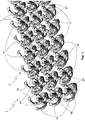
figure 1 shows a perspective view of a jewelry article, object of the present invention, in a first embodiment thereof; -
figure 2 shows a perspective sectional view of the jewelry article made along the trace II-II offigure 1 ; -
figure 3 shows a perspective view of a connection element of the jewelry article offigure 1 in a first embodiment thereof,figure 3 not showing the first tooth according to the invention; -
figure 4 shows a perspective view of a connection element of the jewelry article offigure 1 in a second embodiment thereof; -
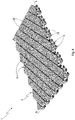
figure 5 shows a perspective view of the jewelry article, object of the present invention, in a second embodiment thereof; -
figure 6 shows a perspective view of a connection element of the jewelry article offigure 5 in a third embodiment thereof,figure 6 not showing the first tooth according to the invention; -
figure 7 shows a perspective view of a connection element of the jewelry article offigure 5 in a fourth embodiment thereof; -
figure 8 shows a perspective view of the jewelry article, object of the present invention, in a third embodiment thereof; -
figure 9 shows a perspective view of a connection element of the jewelry article offigure 8 in a fifth embodiment thereof,figure 9 not showing the first tooth according to the invention; -
figure 10 shows a perspective view of a connection element of the jewelry article offigure 8 in a sixth embodiment thereof; -
figure 11 shows a perspective schematic view of two connection elements of the jewelry article during their formation, in particular during a welding step of the process, object of the present invention; -
figure 12 shows a perspective schematic view of two connection elements of the jewelry article during their formation, in particular during a further welding step of the process, object of the present invention; -
figure 13 shows a perspective schematic view of two connection elements of the jewelry article at the end of the process for making a jewelry article, object of the present invention, with increased proportions in order to better understand such process; -
figure 14 shows a perspective schematic view of two connection elements of the jewelry article at the end of the process for making a jewelry article, object of the present invention. - With reference to the enclosed figures,
reference number 1 overall indicates a jewelry article according to the present invention, which is advantageously obtainable by means of the process, object of the present invention. - The leaf-like jewelry article, object of the present invention, comprises a plurality of
connection elements 2, linked with each other along a lying plane X, in accordance with a first embodiment illustrated infigure 1 , with a third embodiment illustrated infigure 5 and with a third embodiment illustrated infigure 8 . - The
connection elements 2 which form thejewelry article 1, object of the present invention, are made of precious metal, such as gold or platinum. -
Such connection elements 2 are linked together and form a flexible mesh, wearable by a user for ornamental purposes. - According to the idea underlying the present invention, each
connection element 2 comprises at least one firstcommon base 11 defining a firstvisible face 5 of thejewelry article 1 and at least one first internal face. - Each
connection element 2 also comprises at least one secondcommon base 12 defining asecond face 6 of thejewelry article 1 and at least three stems 3, 7, 9 which connect the first internal face of the firstcommon base 11 to the secondcommon base 12 generating, between pairs of thestems corresponding passage openings stems contiguous connection elements 2. - Each
stem like section 20, which projects outside the bulk of the first and the secondcommon base connection element 2 and encloses the intermediate elbow-like section 20 of acontiguous connection element 2. - In this manner, each
connection element 2 is firmly constrained to at least threeconnection elements 2 contiguous thereto, by means of the linking of thestems corresponding passage openings - More in detail, the stems 3, 7, 9 of each
connection element 2 are engaged with corresponding stems 3, 7, 9 ofcontiguous connection elements 2 by means of linking. In other words, the intermediate elbow-like section 20 of thestems connection element 2 encloses and constrains the intermediate elbow-like section 20 of thecorresponding stem contiguous connection element 2. - Advantageously, each first
common base 11 of eachconnection element 2 has a greater size on the lying plane X of thejewelry article 1 than the size on such lying plane X of the secondcommon base 12. - In this manner, the first
common base 11 of eachconnection element 2, which defines the firstvisible face 5 of the leaf-like jewelry article 1, object of the present invention, is adjacent and side-by-side the firstcommon base 11 of thecontiguous connection elements 2, and the secondcommon base 12 of eachconnection element 2 is spaced from the secondcommon base 12 of the contiguous connection elements, allowing a greater mobility of thejewelry article 1. - More in detail, the second
common base 12 of eachconnection element 2 defines the aforesaidsecond face 6, which preferably is not visible when the leaf-like jewelry article 1 is worn by the user. More clearly, the secondcommon base 12 is substantially in contact with the skin (or with the clothes) of the user, and therefore is not visible from the outside. - Advantageously, the second
common base 12 of eachconnection element 2 defines a second internal face facing the first internal face of the first common base. - In operation, in order to wear the leaf-
like jewelry article 1, object of the present invention, the user sets the secondcommon bases 12 of theconnection elements 2 on the desired point. Such secondcommon bases 12, being spaced from each other, allow a relative rotation of theconnection elements 2, i.e. by means of a sliding of thestems like sections 20 of thestems - In this manner, the
article 1 is set on the desired point, by lying on the secondcommon bases 12. The firstcommon bases 11 are adjacent to each other and even after the relative rotation of theconnection elements 2 remain substantially side-by-side, forming an ornamental surface that is pleasing to the sight, since it appears to be continuous in the eyes of an observer. - Advantageously, the first
visible face 5 defined by the firstcommon base 11 can have any shape and any configuration, in order to provide thejewelry article 1 with the desired aesthetic character. - For example, in accordance with the first embodiment illustrated in the enclosed
figure 1 , each firstvisible face 5 of the firstcommon base 11 of eachconnection element 2 is provided with substantially quadrangular form, in particular pyramidal with square base. - In accordance with the second embodiment illustrated in
figure 5 , each firstvisible face 5 of the firstcommon base 11 is provided with a curved shape, which is transversely inserted at the ends thereof below two correspondingvisible faces 6 of curved form of twoadjacent connection elements 2, in order to confer a weave form to thearticle 1, simulating a ribbon weaving. - In accordance with the third embodiment illustrated in the enclosed
figure 8 , each firstvisible face 5 of the firstcommon base 11 is provided with a triangular-plate shape. - According to the invention, each
connection element 2 comprises afirst tooth 13 fixed to at least one of the at least three stems 3, 7, 9, adapted to support acorresponding stem contiguous connection element 2. - Preferably, the second
common base 12 substantially has polygonal or circular plate form, and thestems - Otherwise, in accordance with further embodiments not illustrated in the enclosed figures, the second
common base 12 has annular form, e.g. circular (or toroidal) or polygonal. - In accordance with the embodiments illustrated in the enclosed figures, each
connection element 2 comprises at least threeteeth like section 20 of one of the corresponding at least three stems 3, 7, 9 and substantially extended towards the interior of theconnection element 2 to which they are fixed.Such teeth stem stem like jewelry article 1, object of the present invention, theconnection elements 2 remain substantially aligned along the lying plane X, since theteeth connection elements 2 themselves along an axis transverse to the lying plane X. - In accordance with the first embodiment illustrated in the enclosed
figure 1 and in accordance with the second embodiment illustrated in the enclosedfigure 5 , eachconnection element 2 of the leaf-like jewelry article 1, object of the present invention, comprises at least four stems 3, 7, 9, 16 which connect the first internal face of the firstcommon base 11 to the secondcommon base 12 generating, between pairs of such stems 3, 7, 9, 16, at least fourcorresponding passage openings stems contiguous connection elements 2. - In addition, in accordance with such first and second embodiment illustrated in the enclosed figures, each
connection element 2 comprises fourteeth like section 20 of the latter. - In accordance with further embodiments not illustrated in the enclosed figures, each
connection element 2 can comprise more than four stems 3, 7, 9, 16, for example it can comprise six stems connected to six other respective stems of six separate andcontiguous connection elements 2. In this situation, the first common base has substantially hexagonal shape and the firstvisible face 5 appreciable by the user substantially has honeycomb shape. - In order to increase the mechanical strength of each
connection element 2, in particular tensile strength with respect to a direction substantially transverse with respect to the lying plane X, eachconnection element 2 comprises at least onefirst support column 19 fixed on one side to the first internal face of the firstcommon base 11 and on the other side to the second internal face of the secondcommon base 12. - In accordance with the second embodiment of the
connection elements 2 illustrated infigure 4 which constitute the leaf-like jewelry article 1 in its first embodiment, eachconnection element 2 comprises afirst support column 19 extended along a main extension axis Y of theconnection element 2 itself, parallel to the transverse axis Z and substantially transverse with respect to the lying plane X of thejewelry article 1. Thefirst support column 19 is therefore placed substantially centrally with respect to theconnection element 2 to connect the first and the secondcommon bases first support column 19. - Advantageously, the stems 3, 7, 9 of each
connection element 2 are all provided with the same shape with helically-wound progression and are symmetrically positioned around the main extension axis Y of theconnection element 2 substantially orthogonal to the lying plane X. - Preferably, each
stem connection element 2 defines an angle α at the ends thereof fixed to the firstcommon base 11 comprised between 20° and 70°, and in particular comprised between 30° and 60°. - Such angle α remains defined between each
stem common base 12 of eachconnection element 2 and coincides with the initial angle of the shape helically-wound around the orthogonal axis Z. - Also forming the object of the present invention is a process for making a jewelry article, in particular of the type described up to now and regarding which, for the sake of simplicity, the previously-indicated reference numbers will be maintained.
- The process for making a
jewelry article 1, object of the present invention, initially comprises a step for preparing a three-dimensional drawing file of the desiredjewelry article 1. - More in detail, the step for preparing the file drawing initially provides for a step for designing the desired jewelry article and then its transposition into a three-dimensional drawing file, e.g. by means of a first 3D CAD (Computer-Aided Drafting) software, such as AutoCAD® and the like.
- Advantageously, the step for preparing the three-dimensional drawing provides for providing the
jewelry article 1 with a plurality of second support columns fixed to the secondcommon base 12. - Such second support columns are preferably provided with diameter of several microns, in order to make them easy to remove during a removal step, preferably provided for by the process, object of the present invention, and described more in detail hereinbelow.
- Advantageously, the plurality of second support columns is intended to support the
jewelry article 1 during the welding steps provided for by the process, also described in more detail hereinbelow. - Preferably, the three-dimensional drawing file is saved in a memory of an electronic calculator, e.g. in "3DM" format.
- Advantageously, the first CAD software converts the drawing from the "3DM" format to a "STL" (STereo Lithography interface format) format, which discretizes the three-dimensional drawing into triangles and tetrahedrons, in order to facilitate the electronic calculator for the subsequent operating steps provided for by the process, object of the present invention.
- The process for making a
jewelry article 1 also provides for a step for defining a plurality ofsections 21 of the drawing by means of the intersection of a plurality of dissection planes parallel to the lying plane X with the three-dimensional drawing of thejewelry article 1. - Advantageously, the distance between two
adjacent sections 21 is comprised between 0.005 mm and 0.05 mm and in particular is comprised between 0.01 mm and 0.03 mm. - Such step for defining the
sections 21 is normally attained by means of a second CAD or CAM (Computer-Aided Manufacturing) software which preferably imports the file of the three-dimensional drawing into "STL" format and intersects it with a plurality of surfaces substantially parallel to the lying plane X of thejewelry article 1. - In operation, by means of a graphical interface of the second CAD or CAM software, e.g. by means of the screen of a computer, the operator inserts parameters regarding the distance between the aforesaid parallel surfaces, based on the type of material with which the
jewelry article 1 will be made and based on the type of laser used, as described in detail hereinbelow. - The process also provides for a step for arranging a
welding path 22 within the borders of thesections 21 of thejewelry article 1 and a step for importing thesections 21 of the three-dimensional drawing into a 3D laser printer. - Preferably, the
welding path 22 is entirely contained within the borders of thesections 21 defined during the aforesaid definition step. - The
welding path 22 arranged within the borders of thesections 21 comprises a plurality of curves and segments, which describe the points at which a laser beam will pass, in a welding step described in detail hereinbelow. - The process also provides for the step for welding a powder of precious metals by means of a laser beam of the 3D laser printer along the welding path arranged during the aforesaid arrangement step.
- More in detail, the 3D printer is advantageously of DMLS (Direct Metal Laser Sintering) type, in a manner per se known to the man skilled in the art. The 3D printer comprises a work surface made of metal material on which the precious-metal powder is cyclically set by means of a knife made of rubbery material, in successive layers with thickness preferably equal to the distance between two
adjacent sections 21, and thus with thickness comprised between 0.005 mm and 0.05 mm, and in particular is comprised between 0.01 mm and 0.03 mm. - The laser of the 3D printer is preferably of the type in optical fiber and operating under pulses conditions.
- The welding step is carried out at each section of the three-dimensional drawing of the
jewelry article 1, starting from the section at one of the first and secondcommon bases common bases jewelry article 1. Preferably, such welding step is carried out for each section of the three-dimensional drawing of thejewelry article 1, starting from the section at the secondcommon base 12 up to the section at the firstcommon base 11 of thejewelry article 1. - Advantageously, before actually making the
jewelry article 1, the welding step attains the aforesaid plurality of second support columns, substantially vertical and anchored to the work surface made of metal material. Such second support columns are adapted to support the jewelry article during its attainment and in particular during all the welding steps which are repeated for each section. - During each casting step, the laser beam hits the precious-metal powder at the welding path arranged during the arrangement step and imported into the 3D printer during the step for importing the sections of the three-dimensional drawing of the
jewelry article 1. - The powder made of precious metals hit by the laser beam is heated and quickly reaches the melting point, solidifying at the sections, forming the jewelry article one layer at a time. Indeed, following the melting of a powder layer along the path, the knife transports a new layer of precious-material powder and the 3D printer automatically drives the laser beam to be moved along the path arranged in the subsequent section of the jewelry article.
- Once the section at the first
common base 11 has been solidified, thejewelry article 1 is complete, and theconnection elements 2 are linked together along the lying plane X at the end of the welding steps. - In order to make the
jewelry article 1 reach the desired density, the welding step provides that the segments and the curves that constitute thewelding path 22 are placed at different distances based on the metals that constitute the precious-metal powder and also provides that the speed with which the laser beam travels and the power with which the laser beam hits thewelding path 22 vary based on the aforesaid desired density and based on the metals that constitute the precious-metal powder. - In general, the segments and the curves that constitute the
welding path 22 are placed at an average distance between adjacent segments and/or lines comprised between 0.02 mm and 0.08 mm. - In particular, if the powder of precious metals mainly comprises gold or platinum, the average distance between adjacent segments and/or lines of the
welding path 22 is comprised between 0.02 mm and 0.05 mm. - The speed with which the laser beam travels along the
welding path 22 during each welding step is preferably comprised between 250 and 1300 mm/s. - In particular, if the powder of precious metals mainly comprises gold or platinum, the speed with which the laser beam travels along the
welding path 22 is comprised between 300 and 600 mm/s. - The power of the laser beam during each welding step is preferably comprised between 80W and 130W.
- In particular, if the powder of precious metals mainly comprises gold or platinum, the power of the laser beam is comprised between 95W and 125W.
- The optimal density for the aforesaid precious metals, i.e. gold and/or platinum, is therefore achieved by means of a laser beam provided with the aforesaid travel speeds along the
welding path 22 and with the aforesaid power. - In this situation, the metal cooled and hardened after the welding steps is provided with an internal porosity comprised between 0.1% and 0.3%, which is considered very low by the man skilled in the art.
- Preferably, at the end of the welding step, the method provides for a step for removing the excess precious-metal powder, e.g. manually by means of a brush, so as to recover it in order to be able to use it in making a
new jewelry article 1. - The process, object of the present invention, also advantageously comprises a step of removing the second support columns made during the casting step, which are easily removable since they are very thin.
- In order to avoid damaging the first
visible face 5 of thejewelry article 1, the second support columns are made at thesecond face 6 defined by the secondcommon base 12, which is intended to lie on the skin of the user. Therefore, even if imperfections appear following the removal step, this would not negatively affect the aesthetic result of the jewelry article achieved by means of the process, object of the present invention. - Advantageously, the process also comprises a step of polishing the
jewelry article 1 at the firstcommon base 11 at its firstvisible face 5, in order to make the surface intended to be appreciated by users shiny and pleasing to the eye. - More in detail, the polishing step can be attained, in a manner per se known to the man skilled in the art, by means of the surface diamond-finishing technique, i.e. by means of a diamond disc susceptible of being driven via an electronic control unit and with the numerical control method. In particular, the electronic control unit drives an articulatable arm carrying, mounted thereon, a diamond disc at an end thereof, which is free to rotate, sliding on the first
visible face 5 of the leaf-like jewelry article 1. - Otherwise, the polishing step can be attained by means of sandpapering, per se known the man skilled in the art, and obtained by means of the manual positioning by an operator on an abrasive strip rotated by an electric motor, in order to polish the first
visible face 5 by means of abrasion. - The polishing step can also be advantageously made at the
second face 6 defined by the secondcommon base 12, in order to also make suchsecond face 6 shiny and pleasing to view, suchsecond face 6 being visible when the jewelry article is not worn by the user. - In order to facilitate the polishing step at the first
common base 11 and secondcommon base 12, during the welding step the laser beam is driven to lower the power and/or increase the travel speed along thewelding path 22 during the formation of the firstvisible face 5 and of thesecond face 6, in order to lower the density in proximity thereto, rendering the material more malleable and therefore more easily polishable during the polishing step. - For the same purpose of facilitating the polishing step, the method otherwise provides for increasing the travel speed of the laser beam along the
welding path 22 in order to decrease the energy deposited alongsuch welding path 22 and make the casting of the metal occur at lower temperatures, and thus forming a metal with lower density with respect to the optimal density. - In this situation, the first
visible face 5 and thesecond face 6 are provided with lower density than the density with which the firstcommon base 11 and the secondcommon base 12 are provided, in order to more easily and quickly polish the precious metal that constitutes thejewelry article 1. - In this manner, the jewelry article, object of the present invention, appears quite aesthetically appreciable and has considerable lightness and high mechanical elasticity.
- The finding thus conceived therefore attains the pre-established objects.
- In particular, the
jewelry article 1, object of the present invention, is mechanically strong, light and extremely flexible. - In addition, the
jewelry article 1, object of the present invention, completely lacks blemishes, such as welding points. - In addition, the process, object of the present invention, allows making
jewelry articles 1 with very complex shapes. - In addition, the process for making jewelry articles, object of the present invention, allows an attainment thereof with extremely high precision and in an automated manner.
Claims (11)
- Leaf-like jewelry article comprising a plurality of connection elements (2), linked with each other along a lying plane (X), and each said connection element (2) comprises:- at least one first common base (11) defining a first visible face (5) of said jewelry article (1) and at least one first internal face;- at least one second common base (12) defining a second face (6) of said jewelry article (1);- at least three stems (3, 7, 9) which connect the first internal face of the first common base (11) to the second common base (12) generating, between pairs of said stems (3, 7, 9), at least three corresponding passage openings (4, 8, 10) linked with three stems (3, 7, 9) of three corresponding contiguous connection elements (2);each said stem (3, 7, 9) being extended with a progression substantially helically wound around an axis (Z) orthogonal to said lying plane (X), defining an intermediate elbow-like section (20), which projects outside the bulk of said first and second common bases (11, 12) on said lying plane (X), has concavity directed towards the interior of said connection element (2) and encloses the intermediate elbow-like section (20) of a contiguous connection element (2);
characterized in that each said connection element (2) comprises a first tooth (13) fixed to at least one of said at least three stems (3, 7, 9) adapted to support a corresponding said stem (3, 7, 9) of said contiguous connection element (2). - Jewelry article (1) according to claim 1, characterized in that each said first common base (11) has a greater size on said lying plane (X) than the size on said lying plane (X) of said second common base (12).
- Jewelry article (1) according to claims 1 or 2, characterized in that said second common base (12) defines a second internal face facing the first internal face of said first common base (11);
each said connection element (2) comprising at least one first support column (19) fixed on one side to the first internal face of said first common base (11) and on the other side to the second internal face of said second common base (12). - Jewelry article (1) according to any one of the preceding claims, characterized in that each said connection element (2) comprises at least four stems (3, 7, 9, 16) which connect the first internal face of the first common base (11) to the second common base (12), generating, between pairs of said stems (3, 7, 9, 16), at least four corresponding passage openings (4, 8, 10, 17) linked with four stems (3, 7, 9, 16) of four corresponding contiguous connection elements (2).
- Jewelry article (1) according to any one of the preceding claims, characterized in that each said stem (3, 7, 9) defines an angle (α) at the end thereof fixed to said first common base (11) comprised between 20° and 70°.
- Jewelry article (1) according to any one of the preceding claims, characterized in that said stems (3, 7, 9) are all provided with the same shape with helically-wound progression and are symmetrically positioned around a main extension axis (Y) of said connection element (2) substantially orthogonal to said lying plane (X).
- Process for making a jewelry article (1) according to claim 1, comprising the following operating steps:- a step for preparing a three-dimensional drawing file of said jewelry article;- a step for defining a plurality of sections (21) of said drawing by means of the intersection of a plurality of dissection planes parallel to said lying plane (X) with said three-dimensional drawing of said jewelry article;- a step for arranging a welding path (22) within the borders of the sections (21) of said drawing file of said jewelry article;- a step for importing said sections (21) of said three-dimensional drawing into a 3D laser printer;- a step for welding a powder of precious metals by means of a laser beam of said 3D laser printer along said welding path (22);said welding step being carried out for each section (21) of said three-dimensional drawing of said jewelry article, starting from the section at one of said common bases (11, 12) up to the other of said common bases (12, 11) of said jewelry article;
said connection elements (2) being linked together along said lying plane (X) at the end of said welding steps;
characterized in that said step for preparing a three-dimensional drawing provides for providing the jewelry article with a plurality of second support columns fixed to said second common base (12). - Process for making a jewelry article (1) according to claim 7, characterized in that said welding step is carried out for each section (21) of said three-dimensional drawing of said jewelry article, starting from the section (21) at said second common base (12) up to the section (21) at said first common base (11) of said jewelry article.
- Process for making a jewelry article (1) according to one of claims 7 or 8, characterized in that said plurality of second support columns are made at said second face (6) defined by said second common base (12).
- Process for making a jewelry article (1) according to one of the claims from 7 to 9, characterized in that it also comprises a step of removing said plurality of second support columns.
- Process for making a jewelry article (1) according to one of the claims from 7 to 9, characterized in that said welding step attains said plurality of second support columns, substantially vertical and anchored to a work surface made of metal material of said 3D laser printer.
Priority Applications (1)
| Application Number | Priority Date | Filing Date | Title |
|---|---|---|---|
| EP19204714.0A EP3636098A1 (en) | 2017-05-19 | 2018-05-15 | Jewelry article |
Applications Claiming Priority (1)
| Application Number | Priority Date | Filing Date | Title |
|---|---|---|---|
| IT102017000054760A IT201700054760A1 (en) | 2017-05-19 | 2017-05-19 | ARTICLE OF FOGLIFORME JEWELERY AND PROCEDURE FOR IMPLEMENTING THAT ARTICLE OF JEWELRY |
Related Child Applications (2)
| Application Number | Title | Priority Date | Filing Date |
|---|---|---|---|
| EP19204714.0A Division-Into EP3636098A1 (en) | 2017-05-19 | 2018-05-15 | Jewelry article |
| EP19204714.0A Division EP3636098A1 (en) | 2017-05-19 | 2018-05-15 | Jewelry article |
Publications (2)
| Publication Number | Publication Date |
|---|---|
| EP3403522A1 EP3403522A1 (en) | 2018-11-21 |
| EP3403522B1 true EP3403522B1 (en) | 2019-12-04 |
Family
ID=60020422
Family Applications (2)
| Application Number | Title | Priority Date | Filing Date |
|---|---|---|---|
| EP19204714.0A Withdrawn EP3636098A1 (en) | 2017-05-19 | 2018-05-15 | Jewelry article |
| EP18172417.0A Active EP3403522B1 (en) | 2017-05-19 | 2018-05-15 | Jewelry article and process for making said jewelry article |
Family Applications Before (1)
| Application Number | Title | Priority Date | Filing Date |
|---|---|---|---|
| EP19204714.0A Withdrawn EP3636098A1 (en) | 2017-05-19 | 2018-05-15 | Jewelry article |
Country Status (2)
| Country | Link |
|---|---|
| EP (2) | EP3636098A1 (en) |
| IT (1) | IT201700054760A1 (en) |
Cited By (1)
| Publication number | Priority date | Publication date | Assignee | Title |
|---|---|---|---|---|
| EP4487729A1 (en) | 2023-07-06 | 2025-01-08 | Manufacture d'Horlogerie Audemars Piguet SA | Crimped flexible bracelet, in particular for a wristwatch, and corresponding production method |
Families Citing this family (4)
| Publication number | Priority date | Publication date | Assignee | Title |
|---|---|---|---|---|
| IT201800004760A1 (en) * | 2018-04-20 | 2019-10-20 | PROCEDURE FOR MAKING AN ORNAMENTAL ARTICLE AND ORNAMENTAL ARTICLE OBTAINED THROUGH THIS PROCEDURE | |
| CH715692B1 (en) * | 2018-12-21 | 2024-08-30 | Richemont Int Sa | Link set and link bracelet incorporating this set. |
| CN114054771B (en) * | 2021-09-26 | 2023-03-28 | 中国地质大学(武汉) | Wearable jewelry based on SLM three-dimensional printing technology and preparation method thereof |
| IT202300022182A1 (en) * | 2023-10-24 | 2025-04-24 | Milano Politecnico | VARIABLE STIFFNESS MESH |
Family Cites Families (5)
| Publication number | Priority date | Publication date | Assignee | Title |
|---|---|---|---|---|
| US7501603B2 (en) * | 2005-03-23 | 2009-03-10 | Vojislav Kalanovic | Positioning apparatus and method incorporating modular gimbal unit and jewelry processing system incorporating the positioning apparatus |
| CH700273A1 (en) * | 2009-01-26 | 2010-07-30 | Hanspeter Ott | Producing three-dimensional jewelry pieces made of metal, comprises repeatedly applying a metal powder on a substrate and/or highly-adjustable platform in a layer-wise manner, and partially melting the powder layer at a predetermined point |
| IN2013MU01345A (en) | 2013-04-10 | 2015-04-10 | M S Sunjewels Internat Pvt Ltd | |
| CH709161A1 (en) * | 2014-01-17 | 2015-07-31 | Cartier Création Studio Sa | Piece of jewelry with articulated links, including a watch strap, and its manufacturing process. |
| CN106235540B (en) * | 2016-10-09 | 2018-01-09 | 广州伟栢盈贸易有限公司 | A kind of connected components |
-
2017
- 2017-05-19 IT IT102017000054760A patent/IT201700054760A1/en unknown
-
2018
- 2018-05-15 EP EP19204714.0A patent/EP3636098A1/en not_active Withdrawn
- 2018-05-15 EP EP18172417.0A patent/EP3403522B1/en active Active
Non-Patent Citations (1)
| Title |
|---|
| None * |
Cited By (2)
| Publication number | Priority date | Publication date | Assignee | Title |
|---|---|---|---|---|
| EP4487729A1 (en) | 2023-07-06 | 2025-01-08 | Manufacture d'Horlogerie Audemars Piguet SA | Crimped flexible bracelet, in particular for a wristwatch, and corresponding production method |
| WO2025008157A1 (en) | 2023-07-06 | 2025-01-09 | Manufacture D'horlogerie Audemars Piguet Sa | Flexible set strap, in particular for a wristwatch, and corresponding production method |
Also Published As
| Publication number | Publication date |
|---|---|
| EP3636098A1 (en) | 2020-04-15 |
| EP3403522A1 (en) | 2018-11-21 |
| IT201700054760A1 (en) | 2018-11-19 |
Similar Documents
| Publication | Publication Date | Title |
|---|---|---|
| EP3403522A1 (en) | Jewelry article and process for making said jewelry article | |
| US9027320B2 (en) | Hollow ornaments and process for producing them | |
| CN103394640A (en) | Production method of hollow metal jewelry | |
| Wang et al. | THE EVOLUTION OF CHINESE JADE CARVING CRAFTSMANSHIP. | |
| KR102491940B1 (en) | A three-dimensional pattern cutting method of a precious metal ornament using a diamond cutter blade and multi-axis processing device | |
| KR100358620B1 (en) | Manufacturing method of 3 dimensional gauze accessories using cad/cam | |
| CN109875199B (en) | Jewelry adopting batch flower to inlay precious stones and batch flower to inlay precious stones | |
| WO2020110102A1 (en) | Method and system for generating snowflake-based jewelry | |
| US11117363B2 (en) | Method for making an ornamental article | |
| CN109396760B (en) | A precious metal jewelry production process with dazzling color visual effect | |
| CN101647624B (en) | K gold art engraving and re-embedding process | |
| KR100764041B1 (en) | Molded heat distribution board for dense attachment of jewelry to decorative paper and jewelry attachment method using the same | |
| CA2768696C (en) | Method to create three dimensional image inside stone | |
| CN209862537U (en) | Jewelry adopting batch flowers to inlay jewels | |
| CN213729188U (en) | Wax mould for hollowed-out spherical jewelry | |
| CN214432337U (en) | Mosaic structure of ornament wax mould | |
| CN204070846U (en) | A kind of objects made from precious metals with seven color visual effects | |
| KR20120075931A (en) | A lightweight ring and manufacture method therefor | |
| KR200224163Y1 (en) | 3 dimensional gauze accessories using cad/cam | |
| CN118544726B (en) | Manufacturing method of gold basket precious three-dimensional hollowed-out ornament and hollowed-out utensil | |
| KR100332405B1 (en) | Multi casting type jewelery ornaments and manufacture method for multi casting type jewelery ornaments | |
| KR200419015Y1 (en) | Polishing wheel member that can be curved | |
| CN209711788U (en) | A kind of vehicle flower rabbet structure and its jewellery | |
| CN119344544A (en) | A high-temperature cloisonné enamel process that uses the cat's eye effect principle to create light effect patterns | |
| JP2011078516A (en) | Hoop type earring or pierced earring, and method of manufacturing the same |
Legal Events
| Date | Code | Title | Description |
|---|---|---|---|
| PUAI | Public reference made under article 153(3) epc to a published international application that has entered the european phase |
Free format text: ORIGINAL CODE: 0009012 |
|
| STAA | Information on the status of an ep patent application or granted ep patent |
Free format text: STATUS: THE APPLICATION HAS BEEN PUBLISHED |
|
| AK | Designated contracting states |
Kind code of ref document: A1 Designated state(s): AL AT BE BG CH CY CZ DE DK EE ES FI FR GB GR HR HU IE IS IT LI LT LU LV MC MK MT NL NO PL PT RO RS SE SI SK SM TR |
|
| AX | Request for extension of the european patent |
Extension state: BA ME |
|
| STAA | Information on the status of an ep patent application or granted ep patent |
Free format text: STATUS: REQUEST FOR EXAMINATION WAS MADE |
|
| GRAP | Despatch of communication of intention to grant a patent |
Free format text: ORIGINAL CODE: EPIDOSNIGR1 |
|
| STAA | Information on the status of an ep patent application or granted ep patent |
Free format text: STATUS: GRANT OF PATENT IS INTENDED |
|
| 17P | Request for examination filed |
Effective date: 20190517 |
|
| RBV | Designated contracting states (corrected) |
Designated state(s): AL AT BE BG CH CY CZ DE DK EE ES FI FR GB GR HR HU IE IS IT LI LT LU LV MC MK MT NL NO PL PT RO RS SE SI SK SM TR |
|
| INTG | Intention to grant announced |
Effective date: 20190621 |
|
| GRAS | Grant fee paid |
Free format text: ORIGINAL CODE: EPIDOSNIGR3 |
|
| GRAA | (expected) grant |
Free format text: ORIGINAL CODE: 0009210 |
|
| STAA | Information on the status of an ep patent application or granted ep patent |
Free format text: STATUS: THE PATENT HAS BEEN GRANTED |
|
| AK | Designated contracting states |
Kind code of ref document: B1 Designated state(s): AL AT BE BG CH CY CZ DE DK EE ES FI FR GB GR HR HU IE IS IT LI LT LU LV MC MK MT NL NO PL PT RO RS SE SI SK SM TR |
|
| REG | Reference to a national code |
Ref country code: GB Ref legal event code: FG4D |
|
| REG | Reference to a national code |
Ref country code: CH Ref legal event code: EP |
|
| REG | Reference to a national code |
Ref country code: AT Ref legal event code: REF Ref document number: 1208306 Country of ref document: AT Kind code of ref document: T Effective date: 20191215 |
|
| REG | Reference to a national code |
Ref country code: DE Ref legal event code: R096 Ref document number: 602018001469 Country of ref document: DE |
|
| REG | Reference to a national code |
Ref country code: IE Ref legal event code: FG4D |
|
| REG | Reference to a national code |
Ref country code: CH Ref legal event code: NV Representative=s name: KIRKER AND CIE S.A., CH |
|
| REG | Reference to a national code |
Ref country code: NL Ref legal event code: MP Effective date: 20191204 |
|
| REG | Reference to a national code |
Ref country code: LT Ref legal event code: MG4D |
|
| PG25 | Lapsed in a contracting state [announced via postgrant information from national office to epo] |
Ref country code: LT Free format text: LAPSE BECAUSE OF FAILURE TO SUBMIT A TRANSLATION OF THE DESCRIPTION OR TO PAY THE FEE WITHIN THE PRESCRIBED TIME-LIMIT Effective date: 20191204 Ref country code: BG Free format text: LAPSE BECAUSE OF FAILURE TO SUBMIT A TRANSLATION OF THE DESCRIPTION OR TO PAY THE FEE WITHIN THE PRESCRIBED TIME-LIMIT Effective date: 20200304 Ref country code: FI Free format text: LAPSE BECAUSE OF FAILURE TO SUBMIT A TRANSLATION OF THE DESCRIPTION OR TO PAY THE FEE WITHIN THE PRESCRIBED TIME-LIMIT Effective date: 20191204 Ref country code: LV Free format text: LAPSE BECAUSE OF FAILURE TO SUBMIT A TRANSLATION OF THE DESCRIPTION OR TO PAY THE FEE WITHIN THE PRESCRIBED TIME-LIMIT Effective date: 20191204 Ref country code: SE Free format text: LAPSE BECAUSE OF FAILURE TO SUBMIT A TRANSLATION OF THE DESCRIPTION OR TO PAY THE FEE WITHIN THE PRESCRIBED TIME-LIMIT Effective date: 20191204 Ref country code: GR Free format text: LAPSE BECAUSE OF FAILURE TO SUBMIT A TRANSLATION OF THE DESCRIPTION OR TO PAY THE FEE WITHIN THE PRESCRIBED TIME-LIMIT Effective date: 20200305 Ref country code: NO Free format text: LAPSE BECAUSE OF FAILURE TO SUBMIT A TRANSLATION OF THE DESCRIPTION OR TO PAY THE FEE WITHIN THE PRESCRIBED TIME-LIMIT Effective date: 20200304 |
|
| PG25 | Lapsed in a contracting state [announced via postgrant information from national office to epo] |
Ref country code: RS Free format text: LAPSE BECAUSE OF FAILURE TO SUBMIT A TRANSLATION OF THE DESCRIPTION OR TO PAY THE FEE WITHIN THE PRESCRIBED TIME-LIMIT Effective date: 20191204 Ref country code: HR Free format text: LAPSE BECAUSE OF FAILURE TO SUBMIT A TRANSLATION OF THE DESCRIPTION OR TO PAY THE FEE WITHIN THE PRESCRIBED TIME-LIMIT Effective date: 20191204 |
|
| PG25 | Lapsed in a contracting state [announced via postgrant information from national office to epo] |
Ref country code: AL Free format text: LAPSE BECAUSE OF FAILURE TO SUBMIT A TRANSLATION OF THE DESCRIPTION OR TO PAY THE FEE WITHIN THE PRESCRIBED TIME-LIMIT Effective date: 20191204 |
|
| PG25 | Lapsed in a contracting state [announced via postgrant information from national office to epo] |
Ref country code: EE Free format text: LAPSE BECAUSE OF FAILURE TO SUBMIT A TRANSLATION OF THE DESCRIPTION OR TO PAY THE FEE WITHIN THE PRESCRIBED TIME-LIMIT Effective date: 20191204 Ref country code: RO Free format text: LAPSE BECAUSE OF FAILURE TO SUBMIT A TRANSLATION OF THE DESCRIPTION OR TO PAY THE FEE WITHIN THE PRESCRIBED TIME-LIMIT Effective date: 20191204 Ref country code: NL Free format text: LAPSE BECAUSE OF FAILURE TO SUBMIT A TRANSLATION OF THE DESCRIPTION OR TO PAY THE FEE WITHIN THE PRESCRIBED TIME-LIMIT Effective date: 20191204 Ref country code: CZ Free format text: LAPSE BECAUSE OF FAILURE TO SUBMIT A TRANSLATION OF THE DESCRIPTION OR TO PAY THE FEE WITHIN THE PRESCRIBED TIME-LIMIT Effective date: 20191204 Ref country code: ES Free format text: LAPSE BECAUSE OF FAILURE TO SUBMIT A TRANSLATION OF THE DESCRIPTION OR TO PAY THE FEE WITHIN THE PRESCRIBED TIME-LIMIT Effective date: 20191204 Ref country code: PT Free format text: LAPSE BECAUSE OF FAILURE TO SUBMIT A TRANSLATION OF THE DESCRIPTION OR TO PAY THE FEE WITHIN THE PRESCRIBED TIME-LIMIT Effective date: 20200429 |
|
| PG25 | Lapsed in a contracting state [announced via postgrant information from national office to epo] |
Ref country code: IS Free format text: LAPSE BECAUSE OF FAILURE TO SUBMIT A TRANSLATION OF THE DESCRIPTION OR TO PAY THE FEE WITHIN THE PRESCRIBED TIME-LIMIT Effective date: 20200404 Ref country code: SK Free format text: LAPSE BECAUSE OF FAILURE TO SUBMIT A TRANSLATION OF THE DESCRIPTION OR TO PAY THE FEE WITHIN THE PRESCRIBED TIME-LIMIT Effective date: 20191204 Ref country code: SM Free format text: LAPSE BECAUSE OF FAILURE TO SUBMIT A TRANSLATION OF THE DESCRIPTION OR TO PAY THE FEE WITHIN THE PRESCRIBED TIME-LIMIT Effective date: 20191204 |
|
| REG | Reference to a national code |
Ref country code: DE Ref legal event code: R097 Ref document number: 602018001469 Country of ref document: DE |
|
| REG | Reference to a national code |
Ref country code: AT Ref legal event code: MK05 Ref document number: 1208306 Country of ref document: AT Kind code of ref document: T Effective date: 20191204 |
|
| PLBE | No opposition filed within time limit |
Free format text: ORIGINAL CODE: 0009261 |
|
| STAA | Information on the status of an ep patent application or granted ep patent |
Free format text: STATUS: NO OPPOSITION FILED WITHIN TIME LIMIT |
|
| PG25 | Lapsed in a contracting state [announced via postgrant information from national office to epo] |
Ref country code: DK Free format text: LAPSE BECAUSE OF FAILURE TO SUBMIT A TRANSLATION OF THE DESCRIPTION OR TO PAY THE FEE WITHIN THE PRESCRIBED TIME-LIMIT Effective date: 20191204 |
|
| 26N | No opposition filed |
Effective date: 20200907 |
|
| PG25 | Lapsed in a contracting state [announced via postgrant information from national office to epo] |
Ref country code: SI Free format text: LAPSE BECAUSE OF FAILURE TO SUBMIT A TRANSLATION OF THE DESCRIPTION OR TO PAY THE FEE WITHIN THE PRESCRIBED TIME-LIMIT Effective date: 20191204 Ref country code: AT Free format text: LAPSE BECAUSE OF FAILURE TO SUBMIT A TRANSLATION OF THE DESCRIPTION OR TO PAY THE FEE WITHIN THE PRESCRIBED TIME-LIMIT Effective date: 20191204 Ref country code: PL Free format text: LAPSE BECAUSE OF FAILURE TO SUBMIT A TRANSLATION OF THE DESCRIPTION OR TO PAY THE FEE WITHIN THE PRESCRIBED TIME-LIMIT Effective date: 20191204 |
|
| PG25 | Lapsed in a contracting state [announced via postgrant information from national office to epo] |
Ref country code: MC Free format text: LAPSE BECAUSE OF FAILURE TO SUBMIT A TRANSLATION OF THE DESCRIPTION OR TO PAY THE FEE WITHIN THE PRESCRIBED TIME-LIMIT Effective date: 20191204 |
|
| REG | Reference to a national code |
Ref country code: BE Ref legal event code: MM Effective date: 20200531 |
|
| PG25 | Lapsed in a contracting state [announced via postgrant information from national office to epo] |
Ref country code: LU Free format text: LAPSE BECAUSE OF NON-PAYMENT OF DUE FEES Effective date: 20200515 |
|
| PG25 | Lapsed in a contracting state [announced via postgrant information from national office to epo] |
Ref country code: IE Free format text: LAPSE BECAUSE OF NON-PAYMENT OF DUE FEES Effective date: 20200515 |
|
| PG25 | Lapsed in a contracting state [announced via postgrant information from national office to epo] |
Ref country code: BE Free format text: LAPSE BECAUSE OF NON-PAYMENT OF DUE FEES Effective date: 20200531 |
|
| PG25 | Lapsed in a contracting state [announced via postgrant information from national office to epo] |
Ref country code: TR Free format text: LAPSE BECAUSE OF FAILURE TO SUBMIT A TRANSLATION OF THE DESCRIPTION OR TO PAY THE FEE WITHIN THE PRESCRIBED TIME-LIMIT Effective date: 20191204 Ref country code: MT Free format text: LAPSE BECAUSE OF FAILURE TO SUBMIT A TRANSLATION OF THE DESCRIPTION OR TO PAY THE FEE WITHIN THE PRESCRIBED TIME-LIMIT Effective date: 20191204 Ref country code: CY Free format text: LAPSE BECAUSE OF FAILURE TO SUBMIT A TRANSLATION OF THE DESCRIPTION OR TO PAY THE FEE WITHIN THE PRESCRIBED TIME-LIMIT Effective date: 20191204 |
|
| PG25 | Lapsed in a contracting state [announced via postgrant information from national office to epo] |
Ref country code: MK Free format text: LAPSE BECAUSE OF FAILURE TO SUBMIT A TRANSLATION OF THE DESCRIPTION OR TO PAY THE FEE WITHIN THE PRESCRIBED TIME-LIMIT Effective date: 20191204 |
|
| P01 | Opt-out of the competence of the unified patent court (upc) registered |
Effective date: 20230330 |
|
| PGFP | Annual fee paid to national office [announced via postgrant information from national office to epo] |
Ref country code: DE Payment date: 20250521 Year of fee payment: 8 |
|
| PGFP | Annual fee paid to national office [announced via postgrant information from national office to epo] |
Ref country code: GB Payment date: 20250527 Year of fee payment: 8 |
|
| PGFP | Annual fee paid to national office [announced via postgrant information from national office to epo] |
Ref country code: IT Payment date: 20250528 Year of fee payment: 8 |
|
| PGFP | Annual fee paid to national office [announced via postgrant information from national office to epo] |
Ref country code: FR Payment date: 20250528 Year of fee payment: 8 |
|
| PGFP | Annual fee paid to national office [announced via postgrant information from national office to epo] |
Ref country code: CH Payment date: 20250601 Year of fee payment: 8 |