EP3404163A1 - Verkleidungsvorrichtung einer bodenplatte, und entsprechende verkleidungsanordnung - Google Patents
Verkleidungsvorrichtung einer bodenplatte, und entsprechende verkleidungsanordnung Download PDFInfo
- Publication number
- EP3404163A1 EP3404163A1 EP18170754.8A EP18170754A EP3404163A1 EP 3404163 A1 EP3404163 A1 EP 3404163A1 EP 18170754 A EP18170754 A EP 18170754A EP 3404163 A1 EP3404163 A1 EP 3404163A1
- Authority
- EP
- European Patent Office
- Prior art keywords
- slab
- drainage
- covering
- lateral face
- wall
- Prior art date
- Legal status (The legal status is an assumption and is not a legal conclusion. Google has not performed a legal analysis and makes no representation as to the accuracy of the status listed.)
- Withdrawn
Links
- 238000005253 cladding Methods 0.000 claims abstract description 42
- 125000006850 spacer group Chemical group 0.000 claims description 31
- 230000004888 barrier function Effects 0.000 claims description 3
- XLYOFNOQVPJJNP-UHFFFAOYSA-N water Substances O XLYOFNOQVPJJNP-UHFFFAOYSA-N 0.000 claims description 3
- 230000000295 complement effect Effects 0.000 description 9
- 230000005465 channeling Effects 0.000 description 2
- 235000021183 entrée Nutrition 0.000 description 2
- XAGFODPZIPBFFR-UHFFFAOYSA-N aluminium Chemical compound [Al] XAGFODPZIPBFFR-UHFFFAOYSA-N 0.000 description 1
- 229910052782 aluminium Inorganic materials 0.000 description 1
- 239000000470 constituent Substances 0.000 description 1
- 230000000694 effects Effects 0.000 description 1
- 238000009434 installation Methods 0.000 description 1
- 230000004048 modification Effects 0.000 description 1
- 238000012986 modification Methods 0.000 description 1
- 238000006467 substitution reaction Methods 0.000 description 1
Images


Classifications
-
- E—FIXED CONSTRUCTIONS
- E04—BUILDING
- E04D—ROOF COVERINGS; SKY-LIGHTS; GUTTERS; ROOF-WORKING TOOLS
- E04D13/00—Special arrangements or devices in connection with roof coverings; Protection against birds; Roof drainage ; Sky-lights
- E04D13/15—Trimming strips; Edge strips; Fascias; Expansion joints for roofs
-
- E—FIXED CONSTRUCTIONS
- E04—BUILDING
- E04D—ROOF COVERINGS; SKY-LIGHTS; GUTTERS; ROOF-WORKING TOOLS
- E04D13/00—Special arrangements or devices in connection with roof coverings; Protection against birds; Roof drainage ; Sky-lights
- E04D13/04—Roof drainage; Drainage fittings in flat roofs, balconies or the like
- E04D13/0404—Drainage on the roof surface
- E04D13/0459—Drainage borders, e.g. dripping edges, gravel stops or dispersers
-
- E—FIXED CONSTRUCTIONS
- E04—BUILDING
- E04F—FINISHING WORK ON BUILDINGS, e.g. STAIRS, FLOORS
- E04F11/00—Stairways, ramps, or like structures; Balustrades; Handrails
- E04F11/18—Balustrades; Handrails
- E04F11/181—Balustrades
- E04F11/1812—Details of anchoring to the wall or floor
-
- E—FIXED CONSTRUCTIONS
- E04—BUILDING
- E04F—FINISHING WORK ON BUILDINGS, e.g. STAIRS, FLOORS
- E04F19/00—Other details of constructional parts for finishing work on buildings
- E04F19/02—Borders; Finishing strips, e.g. beadings; Light coves
- E04F19/06—Borders; Finishing strips, e.g. beadings; Light coves specially designed for securing panels or masking the edges of wall- or floor-covering elements
- E04F19/061—Borders; Finishing strips, e.g. beadings; Light coves specially designed for securing panels or masking the edges of wall- or floor-covering elements used to finish off an edge or corner of a wall or floor covering area
-
- E—FIXED CONSTRUCTIONS
- E04—BUILDING
- E04D—ROOF COVERINGS; SKY-LIGHTS; GUTTERS; ROOF-WORKING TOOLS
- E04D13/00—Special arrangements or devices in connection with roof coverings; Protection against birds; Roof drainage ; Sky-lights
- E04D13/04—Roof drainage; Drainage fittings in flat roofs, balconies or the like
- E04D13/0404—Drainage on the roof surface
- E04D13/0459—Drainage borders, e.g. dripping edges, gravel stops or dispersers
- E04D2013/0468—Drip edges
Definitions
- the invention relates to the field of cladding devices of a face of a pending building element, such as a balcony slab.
- An erected building may have, in frontage, one or more suspended structural elements positioned substantially transversely to the building facade, and in the form of a slab comprising an upper face, a lower face, said lower and upper faces being connected to each other by at least one side face.
- these building elements which later will be called slabs, have an upper face extending in a plane inclined relative to the plane in which the underside extends so that the rainwater can be evacuated by runoff to the outside of the building.
- the slab comprises, depending on the position of the latter in the building, between one to three free lateral faces.
- the lateral face substantially parallel to the facade of the building on which the slab is fixed will be named: front face.
- the two opposite side faces and extending transversely to the building facade will respectively be named: first side face and second side side.
- the lateral faces may be covered by a covering device in order to avoid, in particular, the damage associated with rainwater runoff.
- This dressing device comprises a covering wall intended to cover at least partially a side face of a slab, and a discharge wall.
- the covering wall extends in a plane substantially parallel to the plane in which the lateral face of the slab extends.
- the evacuation wall extends in a secant plane, preferably substantially perpendicular to the plane in which the covering wall extends and in a plane substantially extending the plane in which the upper face of the slab.
- the evacuation wall is inclined, said evacuation wall partially covering the covering wall. When it rains, the rainwater flows on the evacuation wall of the cladding device and is removed at a distance from the side face of the slab beyond the cladding device.
- the junction between a cladding device positioned on a side face and a cladding device positioned on a front face becomes complex.
- particular corner pieces are used which require recuts as a function of the inclination of the evacuation wall of the different cladding devices fitted to each lateral face of the slab.
- the invention aims to improve the dressing device described above, by providing a dressing device for the evacuation of rainwater or any other element to be evacuated without the need for grouting operation during installation of said dressing device on a slab while respecting an aesthetic exterior homogeneity.
- the rainwater or any other element to be discharged, flowing on the upper face of the slab is directed into the drainage zone, which allows a simple evacuation of rainwater.
- the evacuation through the drainage zone at a distance from the lateral face of the slab makes it possible to avoid run-off on the slab and the channeling of the rainwater without requiring the grouting operation of the dressing device while respecting an external aesthetic homogeneity.
- the covering wall comprises a member guiding elements to be discharged, said guide member being provided at the drainage inlet of the drainage zone.
- the guide member serves to guide the elements to be evacuated in the drainage zone.
- the guide member is positioned at a proximal end of the cover wall.
- the guide member is formed by the folding of the proximal end of the cover wall.
- the guide member is intended to be positioned between an upper portion of the covering wall and the lateral face to be covered with the slab.
- the covering wall is a profile, preferably of aluminum.
- the covering wall is formed of a single section.
- the covering wall is formed of at least a first profile and a second section, cooperating with each other.
- the covering wall comprises a first cooperation member configured to cooperate with a first complementary cooperation member arranged on the first fixing portion.
- the first cooperation member is a hook having a housing into which is inserted the first complementary cooperation member in the form of a tab formed at a first end of the first fixing portion .
- the covering wall comprises a second cooperation member configured to cooperate with a second complementary cooperation member and arranged on the first fixing portion.
- the second cooperation member is a hook having a housing in which is inserted the second complementary cooperation member in the form of a tab formed at a second end of the first fixing portion .
- the first section partially covers the second section forming a continuous covering wall.
- said cooperation members are arranged towards the lateral face to be covered with the slab.
- the dressing device comprises a recuperator of elements to be evacuated positioned at the drainage outlet of the drainage zone and at the distal end of the covering wall.
- a recuperator of elements to be evacuated positioned at the drainage outlet of the drainage zone and at the distal end of the covering wall.
- the recuperator comprises a first end intended to be fixed directly or indirectly on the slab, preferably on a lower face of the slab.
- the recuperator has a cross section of overall shape in U.
- the recuperator forms a gutter for channeling, at a specific location, the rainwater or the elements to be evacuated when the device covering is attached to a side face to be covered with the slab.
- the recuperator comprises at least one through-hole drainage.
- the rainwater is thus drained towards the through orifice and then removed from the dressing device through said through orifice.
- the recuperator comprises a plurality of through orifices.
- the through orifices are irregularly or regularly spaced.
- the cladding device further comprises a second fixing portion intended to be fixed indirectly on the lateral face to be covered with the slab via a second fixing spacer.
- the second fixing portion is configured to connect the distal end of the cover wall and the recuperator with the side face to be covered with the slab.
- the cladding device further comprises at least a first fixing spacer cooperating with the fixing portion of the cladding device.
- the first fixing spacer is arranged, preferably with a portion extending in a plane generally parallel to the side face to be covered with the slab, to allow the dressing device to be placed at a distance from the lateral face. to cover the slab.
- the first fixing spacer is intended to be fixed on the lateral face to be covered with the slab.
- the cladding device is attached indirectly to the side face to be covered with the slab, the irregularities of the slab thus have no impact on the positioning of the cladding device and particularly on the positioning of the covering wall, the first fixing spacer acting as an interface between the cladding device and the side face to cover the slab.
- the first fixing portion comprises a fixing portion cooperating with the first spacer, said fixing portion extending preferably in a plane substantially parallel to the side face to be covered with the slab.
- the cladding device comprises at least one second fixing spacer cooperating with a second fastening portion of the cladding device.
- the passage of water or elements to be evacuated is carried out in the free space between the slab and the dressing device formed by the first and second spacers.
- the second fixing portion is advantageously formed at the level of the recuperator.
- the second fixing spacer is arranged to allow the remover to be placed at a distance from the lateral face to be covered with the slab.
- the second fixing spacer is intended to be fixed on the side face to be covered with the slab.
- the second fixing portion comprises a fixing portion cooperating with the second spacer, said fixing portion extending preferably in a plane substantially parallel to the side face to be covered with the slab.
- the cladding device may comprise a plurality of fixing struts intended to be fixed between the lateral face to be covered with the slab and the cladding device.
- the invention also relates to a covering assembly comprising a covering device according to the invention and a railing comprising at least one base and a barrier element mounted on the base, the base of said railing being shaped to cooperate with the dressing device.
- the base of the railing is shaped to be positioned at least partially in the drainage inlet of the drainage area. More specifically, the first spacer is arranged on the side face to be covered with the slab so that the covering device, at a distance from said side face to be covered, forms a space corresponding to the drainage inlet. duct, the base of the railing being partially inserted into said space. In this way, the unsightly legs of the railing are hidden by the cladding device.
- the covering assembly comprises a grid having a plurality of through apertures, said grid being positioned at the level of the drainage inlet so as to at least partially mask said drainage inlet.
- the grid covers the entire length of the drainage inlet.
- the size of the through openings of the grid are adapted to the size of the base of the railing so that a base of railing can be inserted and cooperate by complementarity of form with one said through openings.
- the invention also relates to a slab assembly comprising a slab having at least one lateral face and an upper face, and a cladding device according to the invention fixed at least on the lateral face of the slab.
- the drainage inlet is at the level of the upper face of the slab.
- the guide member is positioned between an upper portion of the cover wall and the side face of the slab.
- the first end of the recuperator is attached directly or indirectly to the slab, preferably on a lower face of the slab, opposite the upper face.
- the fixing portion of the second end of the recuperator is fixed directly or indirectly to the lateral face of the slab.
- the first fixing spacer is fixed on the lateral face of the slab.
- the second fixing spacer is fixed on the lateral face of the slab.
- the slab assembly comprises a slab dressing assembly according to the invention.
- the grid is positioned on the drainage inlet, flush with the upper face of the slab.
- the grid is an extension of the upper face of the slab limiting access to the drainage area.
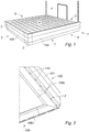
- FIG 1 a facade F of a building comprising a set of slab 1 according to the invention.
- the slab assembly comprises a slab 3 comprising an upper face 4, a lower face 7, and three lateral faces including a front face 5 and two side faces 6, 8.
- the slab assembly 1 further comprises three slider devices. covering 100 each fixed on one of the lateral faces 5, 6, 8 so as to completely cover them.
- the dressing devices 100 are identical and the description of one of them is valid for the other two.
- the covering device 100 has a generally L-shaped cross section so that part of the covering device 100 completely covers a lateral face 5, 6, 8 and a part of the device. covering partially covers the lower face 7 of the slab 3 as illustrated in FIG. figure 2 .
- the cladding devices 100 are joined together by means of corner profiles 2.
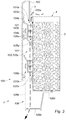
- the covering device 100 comprises a covering wall 101 as illustrated in FIG. figure 3 .
- the covering wall 101 comprises a guide member 102 of elements to be evacuated positioned at a proximal end 101a of the covering wall 101.
- the guide member 102 is formed by the folding of the proximal end 101a of the cover wall 101.
- the guide member 102 is positioned between an upper portion of the cover wall 101 and the lateral face 5 of the slab 3.
- the cladding device 100 further comprises a first fastening portion 106a fixed indirectly on the lateral face 5 of the slab 3 via a first fixing spacer 107a.
- the first fixing spacer 107a is arranged, preferably with a portion extending in a plane generally parallel to the lateral face 5 of the slab 3, to allow the cladding device 100 to be spaced from the lateral face 5 of the slab 3.
- the first fixing portion 106a comprises a fixing portion 109a cooperating with the first spacer 107a.
- the fixing portion 109a extends in a plane substantially parallel to the lateral face 5 of the slab 3. As illustrated in FIG.
- the first fixing strut 107a is fixed on the lateral face 5 of the slab 3.
- the covering device 100 is fixed indirectly on the lateral face 5 of the slab 3, the irregularities of the slab 3 n ' thus have no effect on the positioning of the cladding device 100 and particularly on the positioning of the covering wall 101, the first fixing spacer 107a serving as an interface between the cladding device 100 and the lateral face 5 slab 3.
- the first fixing portion 106a cooperates with the covering wall 101. More specifically, the covering wall 101 comprises a first engagement member 103a configured to cooperate with a first member complementary cooperation 104a and provided on the first attachment portion 106a. As illustrated in figure 3 , the first cooperation member 103a is a hook having a housing in which is inserted the first complementary cooperation member 104a in the form of a tab formed at a first end of the first fixing portion 106a.
- the cover wall 101 comprises a second cooperation member 103b configured to cooperate with a second complementary engagement member 104b and provided on the first attachment portion 106a.
- the second cooperation member 103b is a hook having a housing in which is inserted the second complementary cooperation member 104b in the form of a tab formed at a second end of the first fixing portion 106a.
- the covering device 100 further comprises at least one drainage zone 105 comprising at least one drainage inlet 105a, a drainage outlet 105b, a drainage passage 105c, said drainage passage 105c connecting the drainage inlet 105a with the drainage outlet 105b, said drainage passage 105c being shaped to allow evacuation through the dressing device 100 and at a distance from the at least one side face 5 of slab 3 as illustrated in figure 3 by the dotted arrow.
- the guide member 102 is provided at the drainage inlet 105a of the drainage zone 105.
- the covering device 100 further comprises a recuperator 108 of elements to be evacuated positioned at the drainage outlet 105b of the drainage zone 105 and at the end
- the recuperator 108 comprises a first end 108c fixed directly on the slab 3, preferably on a lower face 7 of the slab 3 as illustrated in FIG. figures 2 and 3 .
- the recuperator furthermore comprises a bottom 108b on which preferential drainage orifices 110 are preferably formed.
- the positioning of the drainage through orifices 110 and their number is not limited to the example illustrated in FIGS. figures 2 , 3 , 6 .
- the through-draining orifices 110 may be arranged, in variants not shown, on an overlapping side wall 108a of the recuperators 108 or else both on the bottom 108c and the lateral covering wall 108a.
- the recuperator 108 comprises a covering side wall 108a arranged in the extension of the covering wall 101 of the covering device 100, set back from said covering wall 101 of the covering device 100 with respect to the axis along which the covering wall 101 extends.
- the cladding device 100 further comprises a second fixing portion 106b indirectly fixed to the lateral face 5 of the slab 3 via a second fixing spacer 107b. More particularly, the second fixing portion 106b comprises a fixing portion 109b cooperating with the second spacer 107b. In the example illustrated in the figures according to the invention and whatever the embodiment, the attachment portion 109b extends in a plane substantially parallel to the lateral face 5 of the slab 3.
- the second attachment strut 107b is arranged, preferably with a portion extending in a plane generally parallel to the face side 5 of the slab 3, to allow the distance of the recuperator 108 from the lateral face 5 of the slab 3 by being fixed on said lateral face 5 of the slab 3 as illustrated in FIG. figure 3 .
- the second fixing portion 106b is configured to connect the distal end 101b of the covering wall 101 and the recuperator 108 with the lateral face 5 of the slab 3.
- the attachment portion 109b of the second attachment portion 106b is attached to the portion of the second spacer 107b by one or more screws.
- the covering device 100 is formed of five sections: a first profile P1 corresponding to a part of the covering wall 101, a second profile P2 gathering another part of the covering wall 101 and the first fixing portion 106a, a third profile P3 comprising the second fixing portion 106b and the recuperator 108 and a fourth and fifth section P4, P5 corresponding to the first spacer 107a and the second spacer 107b.
- the covering wall 101 is formed of a first profile P1 and a second profile P2, cooperating with each other.
- the first profile P1 is equipped with a part of the covering wall 101 as well as the first cooperation member 103a and the second cooperation member 103b as illustrated in FIG. figure 4 .
- the second profile P2 comprises a part of the covering wall 101 and the first fixing portion 106a equipped with the first complementary cooperation member 104a and the second cooperation member 104b as illustrated in FIG. figure 5 .
- the first fixing portion 106a is integrated with the second profile P2 and the second fixing portion 106b is integrated with the recuperator 108 forming a third profile P3 independent of the first profile P1 and the second profile P2 illustrated in FIG. figure 6 .
- the spacers 107a, 107b are illustrated in figure 7 and are identical and are each formed by a profile P4, P5 independent of the other profiles P1, P2 and P3.
- the first section P1 partially covers the second section P2 forming an assembled continuous wall 101, the first cooperation member 103a and the second cooperation member 103b being arranged towards the lateral face 5 of the slab .
- the covering wall 101 has a distal end 101b bent and directed towards the slab 3. The distal end 101b of the covering wall 101 cooperates with the lateral covering wall 108a of the recuperator 108.
- the covering device 100 is formed of five sections: a first profile P1 corresponding to the covering wall 101, a second profile P2 corresponding to the first fixing portion 106a, a third section P3 comprising the second fixing portion 106b and the recuperator 108 and a fourth and fifth section P4, P5 corresponding to the first spacer 107a and the second spacer 107b.
- the covering wall 101 is formed of a single profile P1 as illustrated in FIG. figure 9 .
- the covering wall 101 is thus integral and continuous, the first cooperation member 103a and the second cooperation member 103b being arranged towards the lateral face 5 of the slab 3.
- the first fixing portion 106a is formed of a profile P2 independent of the first section P1.
- the covering wall 101 has a distal end 101b bent and oriented towards the slab 3.
- the distal end 101b of the covering wall 101 co-operates with the lateral covering wall 108a of the recuperator 108.
- the recuperator 108 is formed of a third profile P3 illustrated in FIG. figure 6 independent of the first profile P1 and the second profile P2.
- the spacers 107a, 107b are illustrated in figure 7 and are identical and are each formed by a profile P4, P5 independent of the other profiles P1, P2 and P3.
- the other features described in the first embodiment and not contrary to the second embodiment are valid for the third embodiment.
- cover wall 101 may be formed of one or more profiles.
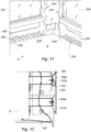
- the invention also relates to a covering assembly 200 comprising a covering device 100 according to the invention and a railing 201 comprising at least one base 202 and a barrier element 203 mounted on the base 202, the base 202 said railing 201 being shaped to cooperate with the dressing device 100 as illustrated in FIG. figure 10 to 12 .
- the dressing assembly 200 will be described regardless of the embodiment of the dressing device 100 used and described above.
- the base 201 of the railing 201 is shaped to be positioned at least partially in the drainage inlet 105a of the drainage zone 105 of the covering device 100. More particularly, the base is positioned substantially perpendicularly or at least in a secant manner. to the guide member 103 of the covering device 100 as illustrated in FIG. figure 11 .
- the first spacer 107a is arranged on the lateral face 5 of the slab 3 so that the covering device 100, at a distance from said lateral face 5, forms a space corresponding to the drainage inlet 105a of the zone of drainage 105 as illustrated in figure 12 , the base 202 of the guard 201 being partially inserted into said space. In this manner, the unsightly legs 202 of the railing 201 are hidden by the cladding device 100 seen from the outside.
- the covering assembly comprises a grid 204 having a plurality of through openings 205, said grid 204 being positioned flush with the upper face 4 of the slab 3, at the drainage inlet 105a so as to mask at the less partially said drainage inlet 105a.
- the gate 204 covers the entire length of the drainage inlet 105a.
Landscapes
- Engineering & Computer Science (AREA)
- Architecture (AREA)
- Civil Engineering (AREA)
- Structural Engineering (AREA)
- Finishing Walls (AREA)
- Building Environments (AREA)
Applications Claiming Priority (1)
| Application Number | Priority Date | Filing Date | Title |
|---|---|---|---|
| FR1754345A FR3066515A1 (fr) | 2017-05-17 | 2017-05-17 | .dispositif d'habillage d'une dalle et ensemble d'habillage associe. |
Publications (1)
| Publication Number | Publication Date |
|---|---|
| EP3404163A1 true EP3404163A1 (de) | 2018-11-21 |
Family
ID=59649855
Family Applications (1)
| Application Number | Title | Priority Date | Filing Date |
|---|---|---|---|
| EP18170754.8A Withdrawn EP3404163A1 (de) | 2017-05-17 | 2018-05-04 | Verkleidungsvorrichtung einer bodenplatte, und entsprechende verkleidungsanordnung |
Country Status (2)
| Country | Link |
|---|---|
| EP (1) | EP3404163A1 (de) |
| FR (1) | FR3066515A1 (de) |
Citations (8)
| Publication number | Priority date | Publication date | Assignee | Title |
|---|---|---|---|---|
| DE29515919U1 (de) * | 1995-10-07 | 1996-10-31 | Stahlbau Seerhausen GmbH, 01594 Seerhausen | Regenwasserablauf für Balkone |
| DE29710371U1 (de) * | 1997-06-13 | 1997-08-14 | Richter, Walter, 49170 Hagen | Stahlrinne für Balkone und Terrassen |
| DE19821785A1 (de) * | 1997-06-10 | 1999-04-08 | Baumjohann Adolf | Mehrteiliger Traufrandabschluß eines flach geneigten Terrassendaches |
| DE20007509U1 (de) * | 2000-04-25 | 2000-07-06 | Schreiner, Therese, 94556 Neuschönau | Balkonverkleidung |
| DE20218833U1 (de) * | 2002-12-05 | 2003-02-27 | Schlüter Systems KG, 58640 Iserlohn | Balkon- und Terrassenabschlussprofil |
| DE102005010629A1 (de) * | 2004-09-17 | 2006-09-28 | Britten, Wolfgang | Modular aufgebautes Randabschlussprofilsystem für Balkone, Terrassen und Flachdächer |
| CH701903A2 (de) * | 2009-09-17 | 2011-03-31 | Uhl Verbundstein Ag | Verkleidungs- und Entwässerungselement für die Stirnseiten von Bauteilen wie Balkone, Terrassen, Laubengänge, Flachdächer und dergleichen. |
| EP2589723A1 (de) * | 2011-11-04 | 2013-05-08 | Dani Alu | Abdeckvorrichtung eines Abschnitts eines hängenden Bauelements |
-
2017
- 2017-05-17 FR FR1754345A patent/FR3066515A1/fr not_active Withdrawn
-
2018
- 2018-05-04 EP EP18170754.8A patent/EP3404163A1/de not_active Withdrawn
Patent Citations (8)
| Publication number | Priority date | Publication date | Assignee | Title |
|---|---|---|---|---|
| DE29515919U1 (de) * | 1995-10-07 | 1996-10-31 | Stahlbau Seerhausen GmbH, 01594 Seerhausen | Regenwasserablauf für Balkone |
| DE19821785A1 (de) * | 1997-06-10 | 1999-04-08 | Baumjohann Adolf | Mehrteiliger Traufrandabschluß eines flach geneigten Terrassendaches |
| DE29710371U1 (de) * | 1997-06-13 | 1997-08-14 | Richter, Walter, 49170 Hagen | Stahlrinne für Balkone und Terrassen |
| DE20007509U1 (de) * | 2000-04-25 | 2000-07-06 | Schreiner, Therese, 94556 Neuschönau | Balkonverkleidung |
| DE20218833U1 (de) * | 2002-12-05 | 2003-02-27 | Schlüter Systems KG, 58640 Iserlohn | Balkon- und Terrassenabschlussprofil |
| DE102005010629A1 (de) * | 2004-09-17 | 2006-09-28 | Britten, Wolfgang | Modular aufgebautes Randabschlussprofilsystem für Balkone, Terrassen und Flachdächer |
| CH701903A2 (de) * | 2009-09-17 | 2011-03-31 | Uhl Verbundstein Ag | Verkleidungs- und Entwässerungselement für die Stirnseiten von Bauteilen wie Balkone, Terrassen, Laubengänge, Flachdächer und dergleichen. |
| EP2589723A1 (de) * | 2011-11-04 | 2013-05-08 | Dani Alu | Abdeckvorrichtung eines Abschnitts eines hängenden Bauelements |
Also Published As
| Publication number | Publication date |
|---|---|
| FR3066515A1 (fr) | 2018-11-23 |
Similar Documents
| Publication | Publication Date | Title |
|---|---|---|
| US8099908B2 (en) | Anti-streak cover for eavestrough | |
| CA2547928C (fr) | Dispositif pour le montage parasismique d'une cloison | |
| CA2608530C (en) | Anti-streak cover for eavestrough | |
| EP3404163A1 (de) | Verkleidungsvorrichtung einer bodenplatte, und entsprechende verkleidungsanordnung | |
| FR2954370A1 (fr) | Plateforme telle que balcon ou terrasse | |
| FR2928394A1 (fr) | Dispositif de guidage combine pour abri telescopique | |
| FR2966854A1 (fr) | Profile et systeme d'integration de panneaux photovoltaiques en toiture et toiture integrant ces elements. | |
| EP2372072B1 (de) | Veranda mit verbesserter Rollladenintegration, und entsprechend angepasster Rollladen | |
| FR2939463A1 (fr) | Dispositif ameliore de support d'un garde-corps | |
| EP2098661B1 (de) | Teleskopisch ausziehbare Überdachungsvorrichtung mit einschieniger Führung | |
| FR2681623A1 (fr) | Dispositif de protection pour travaux sur toiture. | |
| FR2761096A1 (fr) | Organes de maintien d'une grille de securite pour chantier, principalement pour charpentiers ou couvreurs | |
| EP0327481B1 (de) | Befestigungsvorrichtung für Dachziegel | |
| FR2981962A1 (fr) | Sabot de garde-corps a collerette d'etancheite | |
| FR2766223A1 (fr) | Dispositif permettant d'assurer la protection du personnel travaillant sur les toitures | |
| FR2912765A1 (fr) | Abri telescopique a facade mobile integrant des elements de manutention | |
| FR3116291A1 (fr) | Garde-corps comprenant un dispositif d’obturation d’un espace libre | |
| FR2780429A1 (fr) | Echafaudage suspendu a elements modulaires | |
| EP4317629B1 (de) | An einer schalungswand integrierte zubehöraufhängehülse | |
| FR2690186A1 (fr) | Dispositif de recouvrement d'une tranche verticale d'un élément de construction en suspens. | |
| EP2149649A2 (de) | Vorrichtung zum Befestigen einer Geländerhalterung an einem Bauwerk | |
| EP1306498A1 (de) | Befestigungseinrichtung für Platten, insbesondere für Verandadachplatten und Veranda mit einer solcher Einrichtung | |
| CA2498689A1 (fr) | Garde-corps | |
| FR2728923A1 (fr) | Protection pour travaux de couverture | |
| FR2990225A1 (fr) | Garde-corps d'extremite et ensemble comprenant une structure de travail et un garde-corps du type precite |
Legal Events
| Date | Code | Title | Description |
|---|---|---|---|
| PUAI | Public reference made under article 153(3) epc to a published international application that has entered the european phase |
Free format text: ORIGINAL CODE: 0009012 |
|
| AK | Designated contracting states |
Kind code of ref document: A1 Designated state(s): AL AT BE BG CH CY CZ DE DK EE ES FI FR GB GR HR HU IE IS IT LI LT LU LV MC MK MT NL NO PL PT RO RS SE SI SK SM TR |
|
| AX | Request for extension of the european patent |
Extension state: BA ME |
|
| STAA | Information on the status of an ep patent application or granted ep patent |
Free format text: STATUS: THE APPLICATION IS DEEMED TO BE WITHDRAWN |
|
| 18D | Application deemed to be withdrawn |
Effective date: 20190522 |