EP3405639B1 - Zusammenklappbares sicherheitsgitter und gittersystem - Google Patents
Zusammenklappbares sicherheitsgitter und gittersystem Download PDFInfo
- Publication number
- EP3405639B1 EP3405639B1 EP17704098.7A EP17704098A EP3405639B1 EP 3405639 B1 EP3405639 B1 EP 3405639B1 EP 17704098 A EP17704098 A EP 17704098A EP 3405639 B1 EP3405639 B1 EP 3405639B1
- Authority
- EP
- European Patent Office
- Prior art keywords
- bar
- grille
- wall section
- bars
- holes
- Prior art date
- Legal status (The legal status is an assumption and is not a legal conclusion. Google has not performed a legal analysis and makes no representation as to the accuracy of the status listed.)
- Active
Links
Images


Classifications
-
- E—FIXED CONSTRUCTIONS
- E06—DOORS, WINDOWS, SHUTTERS, OR ROLLER BLINDS IN GENERAL; LADDERS
- E06B—FIXED OR MOVABLE CLOSURES FOR OPENINGS IN BUILDINGS, VEHICLES, FENCES OR LIKE ENCLOSURES IN GENERAL, e.g. DOORS, WINDOWS, BLINDS, GATES
- E06B9/00—Screening or protective devices for wall or similar openings, with or without operating or securing mechanisms; Closures of similar construction
- E06B9/02—Shutters, movable grilles, or other safety closing devices, e.g. against burglary
- E06B9/06—Shutters, movable grilles, or other safety closing devices, e.g. against burglary collapsible or foldable, e.g. of the bellows or lazy-tongs type
- E06B9/0607—Shutters, movable grilles, or other safety closing devices, e.g. against burglary collapsible or foldable, e.g. of the bellows or lazy-tongs type comprising a plurality of similar rigid closing elements movable to a storage position
- E06B9/0615—Shutters, movable grilles, or other safety closing devices, e.g. against burglary collapsible or foldable, e.g. of the bellows or lazy-tongs type comprising a plurality of similar rigid closing elements movable to a storage position characterised by the closing elements
- E06B9/063—Bars or rods perpendicular to the closing direction
-
- E—FIXED CONSTRUCTIONS
- E06—DOORS, WINDOWS, SHUTTERS, OR ROLLER BLINDS IN GENERAL; LADDERS
- E06B—FIXED OR MOVABLE CLOSURES FOR OPENINGS IN BUILDINGS, VEHICLES, FENCES OR LIKE ENCLOSURES IN GENERAL, e.g. DOORS, WINDOWS, BLINDS, GATES
- E06B9/00—Screening or protective devices for wall or similar openings, with or without operating or securing mechanisms; Closures of similar construction
- E06B9/02—Shutters, movable grilles, or other safety closing devices, e.g. against burglary
- E06B9/06—Shutters, movable grilles, or other safety closing devices, e.g. against burglary collapsible or foldable, e.g. of the bellows or lazy-tongs type
- E06B9/0607—Shutters, movable grilles, or other safety closing devices, e.g. against burglary collapsible or foldable, e.g. of the bellows or lazy-tongs type comprising a plurality of similar rigid closing elements movable to a storage position
- E06B9/0646—Shutters, movable grilles, or other safety closing devices, e.g. against burglary collapsible or foldable, e.g. of the bellows or lazy-tongs type comprising a plurality of similar rigid closing elements movable to a storage position characterised by the relative arrangement of the closing elements in the stored position
- E06B9/0653—Shutters, movable grilles, or other safety closing devices, e.g. against burglary collapsible or foldable, e.g. of the bellows or lazy-tongs type comprising a plurality of similar rigid closing elements movable to a storage position characterised by the relative arrangement of the closing elements in the stored position stored side by side in the closing plane
Definitions
- the invention relates to a collapsible security grille according to the claim 1 and to a security grille system with such collapsible security grille.
- a collapsible security grille and security grill system are for example known from KR20150027017 .
- Said collapsible security grilles can be for securing a passage such as a doorway or window at least partly.
- the security grille may be to screen off and/or protect for instance shops, business establishments, warehouses, kitchens, schools, parking garages, etc. and/or for partitioning spaces, for instance in a shopping center or an airport terminal building.
- stackable security grilles comprising a multiplicity of successive bars that can be substantially stacked in a retracted state of the grille and can be substantially spaced apart with respect to each other in an extended state of the grille.
- said bars can extend substantially horizontally, and may at outer ends be guided within a guide profile or guide bar.
- the bars may be provided with series of corresponding through holes or passages for allowing elongated connecting elements, such as rods, to pass through at least a number of the bars.
- Such connecting element preferably its upper end or lower end, can be fixedly connected to a respective one of the bars.
- the opposite end of the connecting element may be provided with a retainer element, in particular a thickening or lateral protruding portion such as a so-called head.
- the passage in the bar adjacent to the bar to which the connecting element is fixated can be wide enough to allow a shaft of the connecting element to pass, but can be narrow enough to block the retainer element of the connecting element from passing there through.
- One or multiple subsequent bars can have corresponding holes, preferably though holes, that are wide enough to allow the retainer element to pass through there and/or to be accommodated therein at least partly when the security grille is collapsed.
- the bars are made from metal tubes or pipes having a substantially square or substantially rectangular cross-section. After providing said tube or pipe, an upper wall of the hollow tube or pipe is being provided with a first hole pattern and a lower wall of the hollow is being provided with a second hole pattern corresponding to the first hole pattern. Said hole patterns are usually laser cut into the respective tube wall.
- a passage in the bar used for blocking the retainer element can be formed by a relatively narrow first hole in a first tube wall, e.g. the upper wall, for blocking the retainer element and a corresponding relatively wide second hole in a second tube wall, e.g. the bottom wall, which can allow the retainer element to enter the tube or bar such as to be kept out of sight substantially in the extended state of the security grille.
- all holes may have a substantially equal diameter and the passages that are mentioned to block the retainer element, or so-called heads, can be provided by a bush or bushing that narrows the passage formed by two corresponding through holes in opposite wall sections of the tube forming the bar.
- An object of the present disclosure is to provide an alternative collapsible, in particular stackable, security grille, and/or an alternative method for manufacturing a collapsible security grille. It is an object of the present disclosure to alleviate or solve at least one disadvantage of one or more known stackable security grilles. In particular, it can be considered an object of the disclosure to alleviate or solve at least one disadvantage mentioned above. More in particular, the invention may aim to provide a collapsible security grille which can be produced in a manner that is relatively cost efficient, relatively little prone to errors, relatively easily, and/or relatively fast. In embodiments, the invention aims at providing a collapsible, especially stackable, security grille without laser cutting holes in walls or wall sections of pipes or tubes for forming bars of the grille.
- a collapsible security grill according to claim 1 is provided.
- holes in opposite walls or wall sections of the final bar can in embodiments be formed before a substantially hollow bar is formed from said one or more bar parts from bent sheet metal. This may for instance allow that holes can be punched, e.g. while or after a blank is formed for forming the bar or a respective part of the bar. In stead of laser cutting holes in respective walls or wall sections of a purchased pipe, holes may thus be formed in a relatively cost efficient, relatively easy, and/or relatively foolproof manner.
- a first bar part can be formed which comprises a wall or wall section for forming an upper wall or upper wall section of the final bar.
- Said first wall section or wall can then be provided with holes, which holes will later form the holes in said upper wall section or upper wall of the final bar.
- Said holes made in said first wall or first wall section can be made without any second wall or second wall section for forming a lower wall or lower wall section of the final bar hindering that said holes are made in said first wall or first wall section, because a second bar part comprising said second wall or second wall section can be absent.
- the holes in the first wall or first wall section can be made in a first blank, before said first blank is bent in order to deform it into the first bar part.
- holes in the second wall or second wall section can be made in a second blank before said second blank is bent in order to deform it into the second bar part.
- first pattern of holes in the first wall or first wall section of the final bar and the second pattern holes in the second wall or second wall section of the final bar may be formed in a single blank and said single blank may subsequently be bent into a bar or into a bar part, especially in a manner that the holes of the first and second pattern pair up into pairs of corresponding holes for forming passages through the final bar.
- Each of at least a number of the bars is put together from at least a first part formed from a first blank of sheet metal and a second part formed from a second blank of sheet metal. At least the first part and/or at least the second part is formed as a bent profile.
- a second bar part extending at least partly within another, e.g. first, bar part, can extend from said first bar part in order to couple two first bar parts together. This is, a second bar part may thus overlay with two first bar parts that are placed in line and succeed each other in their longitudinal direction.
- the second or inner bar part can then counteract that the consecutive first or outer bar parts can be moved with respect to each other in a direction substantially transverse to their longitudinal directions.
- relatively long bars can be composed in a relatively easy manner, which may facilitate forming relatively wide grilles that are relatively strong in a relatively simple and/or cost efficient manner.
- the first part can be at least partly enclosing the second part and/or the first part may define a hollow room for accommodating the second part at least partly in an assembled state of the bar.
- a bar part especially the first bar part, may comprise one or multiple supports or retaining elements.
- Said one or more supports or retaining elements may be for supporting a further bar part, especially the second part. Additionally or alternatively, said one or more supports may be for facilitating retaining said further bar part at least partly within the bar part provided with one or more retaining elements or supports.
- the two bar parts are both bent such as to have a substantially C-shaped cross-section for a first bar part and a C-shaped or U-shaped cross-section for a second bar part.
- the first bar part can be formed such as to have a cross-section substantially shaped as an inverted U, having inwardly extending supports at the ends of its "legs" or strokes.
- the second bar part which then for instance can be formed such as to have a U-shaped cross section, can then be positioned at least partly into a hollow space within the first part.
- the bar can have side walls or side wall sections that comprise multiple layers, e.g. two layers, whereas the bottom and upper walls or wall sections may then comprise less layers than the side walls or walls sections.
- the top and/or the bottom of the bar may comprise a single layer.
- the first part and the second part can move with respect to each other to some extent.
- the first part and the second part do thus not need to be fixedly attached to each other.
- the second part can be moved with respect to the first bar part to at least a small extent in at least a direction substantially parallel with the longitudinal direction of the bar.
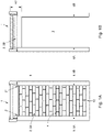
- Figures 1A and 1B show a first embodiment of a collapsible security grille system 1 having a collapsible security grille 2 situated in its extended state 2A and its collapsed or so-called retracted state 2B, respectively.
- the collapsible security grille 2 can be a stackable security grille.
- the stackable and/or collapsible security grille 2 may be suitable for securing a passage 3 at least partly, and can be arranged to be brought from an extended state 2A, in which the grille 2 can block the passage 3 at least partly, into a retracted state 2B, in which at least a part of the previously blocked part of the passage 3 is unblocked.
- the passage 3 which can be formed as a door opening, in the embodiment shown in Figs. 1A and 1B has a width which is smaller than its height
- the collapsible security grille 2 and/or a security grille system 1 having the collapsible security grille 2 may in alternative embodiments have a relatively large width, preferably a width being larger than the height of the grille in extended state 2A.
- the collapsible security grille 2 comprises a multiplicity of successive bars 4.
- the bars 4 can be substantially stacked in a retracted state of the grille 2.
- the grille 2 can be retracted upwardly, as in the shown embodiments, the grille 2 may be retractable downwardly in other embodiments.
- the stack of stacked bars 4 may then be accommodated within a cavity in the ground or floor, which cavity can then thus be located below the passage 3.
- the bars 4 can be substantially spaced apart with respect to each other in the extended state 2A of the grille 2.
- the bars 4 can preferably extend substantially parallel to each other and/or that the bars 4 may preferably be substantially horizontally extending beams 4. However, in alternative embodiments, the bars 4 may extend in a different direction. For example, the bars 4 can extend substantially vertically and the grille 2 may be retractable in a sideward direction.
- the bars 4 can be connected by means of multiple elongated connecting elements 5 for interconnecting respective bars 4.
- Said connecting elements 5 can substantially be formed as and/or may comprise a pin or peg.
- said connecting elements 5 may extend substantially transverse to the longitudinal direction of the bars 4 and/or substantially vertically, said connection elements 5 may extend in a different direction in alternative embodiments.
- the connecting elements 5 may in alternative embodiments extend substantially horizontally.
- At least a number of the multiplicity of elongated connecting elements 5 may each be arranged for interconnecting two respective spaced apart bars in the extended state of the security grille 2 in such a manner that the respective connecting element 5 counteracts that a first one 4A and a second one 4B of said two spaced apart bars 4A, 4B can be moved apart substantially further with respect to each other.
- said respective connecting element 5, 5A can be attached to the first bar 4A.
- a distal end of the connecting element 5 can be attached to the bar 4.
- Said distal end may preferably be an upper end of the connecting element 5 in case of an upwardly extending connecting element 5.
- the connecting element 5 may be riveted to the bar or a respective bar part 42, e.g. by means of a blind rivet.
- the connecting element may be connected by other means, e.g. by means of bolting, screwing 11, welding, etc.
- said respective connecting element 5, 5A can be provided with retainer element 7, e.g. a thickening 7 or lateral protruding portion 7, for limiting the distance D1 over which the first and second bars 4A, 4B can be spaced apart in the extended state 2A of the security grille 2.
- Said retainer element 7, which may be considered a retainer head 7, can preferably be located at a distal end of the connecting element 5, more preferably, in case of upwardly extending connecting elements, its lower end.
- Said second bar 4B can have a passage 6, 60B for allowing the second bar 4B to be moved along a part, e.g. a shaft 5', of the elongated connecting element 5, wherein said passage 60B is arranged to block the retainer element 7 from passing there through.
- the passage 6, 60B may be narrower or tighter than and at another point, e.g. at or near a lower end or side 4B" of the bar 4, 4B.
- the passage 6, 60B may be narrower or tighter than and at another point, e.g. at or near a lower end or side 4B" of the bar 4, 4B.
- the passage 6, 60B may be smaller at a side 4B' of the second bar 4B facing towards the first bar 4A than at the opposite, second side 4B" of the second bar 4B, which second side 4B" is facing away from the first bar 4A and is facing to a third bar 4C.
- the retainer element 7 of said connecting element 5, 5A can enter into the second bar 4B via a relative wide part 60B" of said passage 60B and can subsequently be stopped by a relative small part 60B' of said passage 60B which then can counteract that the first bar 4A and the second bar 4B can be moved further apart from each other.
- the respective retainer element 7 can be accommodated at least partly within the second bar 4B in the extended state 2A of the security grille 2.
- the narrowing passage 6, 60B in the second bar 4B can be formed by a first through hole 60B' provided in a first wall section 45A of said second bar 4B and second through hole 60B" provided in a second wall section 45B of said bar 4B located opposite said first wall section 45A. Said first wall section 45A of the second bar 4B may then be facing the first bar 4A, while the second wall section 45B of the second bar 4B may be facing a third bar 4C located at the opposite side of the second bar 4B as the first bar 4A.
- the third bar 4C, and preferably one or more further subsequent bars 4D, 4E, are provided with corresponding passages 61C, 61D, 61E for allowing the connecting element 5, 5A and its retaining element 7 to enter said passages 61C, 61D, 61E and preferably to pass through said passage 61C, 61D, 61E in order to enter one or more following bars 4C, 4D, 4E.
- the connecting element 5, 5A can extend through multiple subsequent bars 4B, 4C, 4D, 4E in the so-called retracted, packed, stacked, compacted or collapsed state 2B of the grille 2, as can be seen in Fig. 2B .
- said corresponding passages 61C, 61D, 61E in the third and further bars 4C, 4D, 4E through which said retaining element 7 has to pass during the collapsing of the grille 2 has to be wide W1 enough to allow the retaining element 7 to pass and should thus be wider than smallest part 60B' of the corresponding passage 60B in the second bar 4B which is arranged to block said retainer element 7 from passing there through.
- the collapsible and/or stackable security grille 2 can be part of a security grille system 1 arranged for stacking the bars 4 in the retracted state 2B and for subsequently bringing the bars 4, or at least a part of the bars 4, back to the extended state 2A of the grille 2.
- the grille system 1 may for instance comprise at least one bar guide 8, e.g. a guiding profile 8, for guiding the bars 4 when moving from the retracted state 2B toward the extended state 2A or vice versa and/or for counteracting that the bars 4 , or at least respective parts thereof, can be moved in a transverse direction substantially transverse to the direction D2 in which the bars 4 extend and substantially transverse to the direction D1 in which the bars 4 are substantially spaced apart in the extended state 2A.
- a respective bar guide 8A, 8B may be provided for guiding end portions 4', 4" of the bars 4.
- the grille system 1 may comprise an actuator, e.g. a motor, such as an electromotor, for driving the grille, e.g. from its retracted or stacked state 2B to its extended state 2A or vice versa.
- an actuator e.g. a motor, such as an electromotor, for driving the grille, e.g. from its retracted or stacked state 2B to its extended state 2A or vice versa.
- the grille system 1 may comprise a moving member, preferably a lifting member, such as a cable or chain, for moving, e.g. lifting, at least a part of the bars 4.
- a moving member preferably a lifting member, such as a cable or chain, for moving, e.g. lifting, at least a part of the bars 4.
- the security grille system 1 may further comprise a chain 70 connected to the grille 2, preferably a chain 70 being flexible in only one dimension and/or being roller chain 70, and at least one chain limiting member 71 for at least locally limiting movement of the chain, e.g. in a direction in which it is flexible, such as to counteract that one or more links of the chain can be substantially moved away from a regular route along which the links move when the grille 2 is moved from its extended state 2A to its retracted state 2B or vice versa.
- the chain 70 may be attached to a bottom one 4Z of the bars 4, e.g. by means of a connector 72, such as a bolt or the like.
- Said bottom one 4Z of the bars may have a relatively large height compared to the other bars 4 in order to accommodate respective connecting elements 5 therein in the retracted state 2B of the grille 2.
- the chain limiting member 71 can preferably be formed by means of a limiting profile 71, which may for instance be located within and/or parallel with a respective bar guide 8 or bar guiding profile 8.
- Fig. 3A shows a schematic perspective view of an embodiment of a bar 4 for a collapsible security grille 2 according to an aspect of the disclosure.
- the bar 4 is a substantially hollow bar.
- the substantially hollow bar 4, 4B can have a first wall section 45A which during use faces towards an adjacent bar 4A preceding said substantially hollow bar 4B and a second wall section 45D facing towards a subsequent bar 4C succeeding said substantially hollow bar 4B.
- the first wall section 45A can be provided with a number of first holes 62A, 63A
- the second wall section 45D can be provided with a number of corresponding second holes 62D, 63D.
- Respective ones 62D, 63D of the second holes can then form pairs 62B, 63B with a respective one 62A, 63A of the first holes.
- Such pair of holes 62B, 62D; 63B, 63D, for instance together with a certain portion of a hollow room 43 within the bar 4, may then thus form a passage 6 through the bar 4.
- Said pair of holes and/or said passage can allow a respective one of the connecting elements 5 to extend there through.
- the substantially hollow bar 4 can have at least two sections 45B, 45C defining side walls of the bar 4. Each of said two side wall defining sections 45B, 45C can extend from the first wall section 45A towards the second wall section 45D or vice versa. It is noted that the elongated connecting elements may extend at least partly between two side wall sections 45B, 45C of the substantially hollow bar 4.
- the bar 4 has a substantially rectangular cross-section.
- Said cross-section can have a width W4 being larger then the height H4 of the bar, e.g. a width W4 being between 1.5 and 2.5 times wider than said height H4, preferably about 2 times wider.
- a relatively wide width e.g. between 20 and 60 mm, preferably between 25 and 40 mm, such as for instance about 30 mm, can allow for relatively wide passages 6, and therefore for relatively thick and strong connecting elements 5, whereas a relatively small height H4 can facilitate that the grille 2 has a relatively small height H2 when its bars 4 are stacked in the collapsed state 2B of the grille 2.
- the cross-section may be formed differently.
- the bars may have a relatively large height and/or a different shape, e.g. having a substantially square, circular or elliptical shape.
- the side wall or side wall sections 45B, 45C of the bar 4 may substantially smoothly blend into the first and/or second wall section 45A, 45D, which may form an upper and/or a bottom wall section.
- the bar 4 comprises two parts 41, 42 formed from a blank of sheet metal and/or bent sheet metal, especially bent steel sheets or bent steel plates.
- the bar 4 such as the exemplary embodiment shown in Fig. 3A , may thus comprise two parts 41, 42, both formed from bent sheet metal, the bar 4 may in alternative embodiments comprise more than two parts, e.g. three, four or five parts. At least one of said one or multiple parts 41, 42 is formed from bent sheet metal, and one or more other parts of the bar 4 may be formed differently, for instance may be formed as a non-bent metal sheet part.
- the metal sheet can be a purchase part and/or can have a standard thickness.
- the thickness of the steel sheet of which one or multiple parts can be formed can for instance be about 1 mm, 1.2, 1.5 mm, 2 mm, 2.5 mm, 3 mm or 4mm, preferably about 2 mm.
- the metal sheet especially steel sheet, may be pre-galvanized, pre-coated or pre-painted.
- the metal sheet especially steel sheet, may be provided with a zinc-aluminum-magnesium coating, such as for instance the Magnelis ® coating marketed by ArcelorMittal.
- the zinc-aluminum-magnesium coating can be an alloy comprising, and preferably substantially consisting of, zinc, aluminum and magnesium.
- the alloy may comprise at least 1%, 1.5%, 2% or 2.5% magnesium, such as for instance about 3% magnesium, at least 1.5%, 2%, 2.5% or 3% aluminum, such as for instance about 3.5% aluminum, and/or at least 80%, 85%, 90% or 92% zinc, such as for instance about 93.5% zinc.
- the zinc-aluminum-magnesium coating can be applied to the sheet by means of a continuous hot dip galvanizing process.
- An advantage of the zinc-aluminum-magnesium coating, especially the Magnelis ® coating can lie in its self-repairing properties. For example, holes cut, especially punched or clipped or via another shearing technique, in a pre-coated sheet will have cut edges that can be protected by such coating.
- the coating, especially the Magnelis ® coating can protect exposed cut edges with a relatively thin zinc-based protective film with magnesium, which prevents corrosive reactions. As a result, it may be superfluous to treat, e.g.
- the pre-coated sheet in particular steel sheet, more in particular a steel sheet pre-coated with a zinc-aluminum-magnesium coating, especially a Magnelis ® coating, after holes have been cut, especially punched, in said pre-coated sheet.
- Each of at least a number of the bars 4 of a security grille 2 can be put together from at least a first part 41 formed from a first blank of sheet metal and a second part 42 formed from a second blank of sheet metal. Both bar parts 41, 42are bent profile.
- the first part 41 is at least partly enclosing the second part 42, and/or the first bar part 41 defines a hollow room 43 for accommodating the second part 42 at least partly in an assembled state of the bar 4.
- the second part 42 can be locked within the first part 41 in such manner that the second part 42 is substantially prevented from tilting or rotation about its central or longitudinal axis, e.g. letting the bar have a substantially rectangular cross-section.
- a bar part may comprise one or multiple supports 44 or retaining elements 44.
- Said one or more supports 44 or retaining elements 44 may be for supporting a further bar part, especially the second part 42. Additionally or alternatively, said one or more supports 44 or retaining elements 44 may be for facilitating retaining said further bar part 42 at least partly within the bar part 41 provided with said one or more retaining elements 44 or supports 44.
- Said supports 44 may for instance extend from a respective side wall section layer 41B, 41C in a substantially inward direction.
- a first support 44A extending from a first side wall section layer 41B in a substantially inward direction can extend substantially toward a second support 44B that is extending from a second side wall section layer 41B in a substantially inward direction.
- one or more supports 44 can be formed by bending or folding over parts of a blank.
- the supports 44 may for instance be formed by edges 44 of a profile 41 forming the respective bar part 41, especially the first bar part 41.
- the supports 44 are shaped as edges or strips, the supports may be formed differently.
- one or both side wall section forming portions 41B, 41C of the first part 41 may be provided with one or multiple fingers for supporting the second part 42.
- the first bar part 41 can be bent such as to have a substantially C-shaped or U-shaped cross-section, especially formed as an inverted U having inwardly extending supports 44 at the ends of its "legs" 41B, 41C or strokes 41B, 41C.
- the second bar part 42 which then for instance can be formed such as to have a U-shaped cross section, can then be positioned at least partly into a hollow space 43 within the first part 41.
- At least one, and preferably both, of the side wall sections 45B, 45C of the bar 4 can comprise multiple layers 41B, 42B; 41C, 42C of sheet metal.
- one or both of said side wall sections 45B, 45C of the bar 4 can be put together from at least a first side wall section layer 41B; 41C formed by the first part 41 and at least a second side wall section layer 42B; 42C formed by the second part 42.
- the first part 41 of the bar 4 can have a first wall section 41A being provided with a number of first holes 62A, 63A. Said first wall section 41A of the first part 41 may form at least a part of the first wall section 45A of the bar 4 or may alone form said first wall section 45A of the bar.
- the first part 41 can further have two side wall section layers 41B, 41C each forming a layer 41B, 41C of a respective side wall section 45B, 45C of the bar 4.
- the first bar part 41 may thus comprise two interspaced side wall sections 41B, 41C, and said first wall section 41A can then form an intermediate wall section interconnecting said two side wall sections. Said side wall sections of the first part can form first side wall section layers of the substantially hollow bar.
- the second part 42 of the bar 4 can comprise the second wall section 45D of the bar 4, or at least a layer 42D thereof.
- the second part 42 may comprise two interspaced side wall sections 42B, 42C, and the second wall section layer 42D can then form an intermediate wall section 42D interconnecting said two side wall sections 42B, 42C.
- Said side wall sections 42B, 42C of the second part 42 can form second side wall section layers of the substantially hollow bar.
- the side wall sections 41B, 41C of the first part 41 may cooperate with said side wall sections 42B, 42C of the second part 42 in order to form side wall sections 45B, 45C comprising multiple layers, i.e. at least two layers. Since the first part 41 may enclose the second part 42 at least partly, said first side wall sections 41B, 41C formed by the first part 41 may be located at outer sides of the second side wall sections 42B, 42C formed by the second part 42. As a result of the multiple layers 41B, 42B; 42B 42C, the side wall sections 45B, 45C of the bar 4 may be relatively thick, relatively stiff, and/or relatively strong.
- first and second wall sections 45A, 45B of the bar 4 can be substantially formed by a single layer of sheet metal.
- the first bar part 41 especially formed as a first profile 41
- the second bar part 42 especially formed as a second profile 42, may comprise the second wall section 45D.
- upper and lower wall sections 45A, 45D of the bar may not need to be as stiff as side wall sections 45B, 45C of the bar 4, it can be an advantage that said upper and lower wall sections 45A, 45D can be relatively thin, e.g. being composed from relatively few layers, preferably comprising a single layer of sheet metal only.
- material can be saved for the first and/or second wall sections 45A, 45D.
- the bars made from bent sheet metal e.g.
- the grille 2 composed from multiple bar parts, can have relatively strong, rigid and/or thick side walls or side wall sections, while having relatively thin and/or light top and/or bottom walls or wall sections. Economizing on material may not only save money due to limited use of material, but may also result in relatively light bars. Due to weight savings, an actuator for stacking and unstacking, i.e. extending, the grille 2 may be of a relatively light and/or cheap version.
- the first part 41 and the second part 42 of the bar are not fixedly attached to each other, such that the second part 42 can be moved with respect to the first part 41 to some extent.
- the second part 42 can be moved with respect to the first bar part 41 to at least a small extent in at least a direction substantially parallel with the longitudinal direction D2 of the bar 4.
- the bar 4 and/or the grille 2 can allow for some play, as a result of which can be counteracted that bars 4 may unintentionally get stuck, e.g. in or between bar guide 8A, 8B guiding the grille 2 when being extended or collapsed.
- the grille 2 or the grille system 1 can comprise one or multiple, especially two, elongated relatively rigid guiding elements 73, e.g. formed as a rod, rail, bar or tube, extending through multiple succeeding bars 4.
- elongated guiding elements 73 may preferably be located at or near a respective end portion 4', 4" of the bar 4.
- the elongated guiding elements 73 may be located within a respective bar guide 8A, 8B, such that said elongated guiding elements 73, which do not retract during collapsing of the grille 2, will not block a part of the passage 3 when the grille 2 is in its collapsed state (see Fig. 1B ).
- the elongated guiding elements 73 Due to the one or multiple elongated guiding elements 73 extending through through holes through the bar parts 41, 42 of succeeding bars, 4 mutual movement of the bar parts 41, 42 of a bar 4, e.g. at least in their axial or longitudinal direction D2, can be limited or counteracted, which for instance can counteract jamming.
- An additional or alternative advantage of the guiding elements 73 may be that they can give extra firmness to the grille 2 or grille system 1.
- the elongated guiding elements 73 can at least partly transmit forces exercised on one of the bars 4 to one multiple of the other bars. As a result, e.g.
- the grille 2 may more or less act as a whole, for instance to counteract that one of the bars is levered or wrenched out of the respective bar guide 8A, 8B.
- a tampering force applied to a certain bar may be transferred to another bar and the multiple bars may transmit the initial tampering force over different regions of the bar guide(s), which may result in a relatively strong grille system 1.
- the guiding elements 73 and the corresponding through holes in the bars 4 have a circular cross-section in the embodiment shown in Fig. 4 , it will be appreciated that they may have alternative shapes, e.g. rectangular, oval, etc. in alternative embodiments.
- a first bar part and a second bar part do not need to have similar lengths.
- a relatively long first bar part can hold multiple relatively short second bar parts.
Landscapes
- Engineering & Computer Science (AREA)
- Structural Engineering (AREA)
- Architecture (AREA)
- Civil Engineering (AREA)
- Packaging Of Annular Or Rod-Shaped Articles, Wearing Apparel, Cassettes, Or The Like (AREA)
- Burglar Alarm Systems (AREA)
Claims (7)
- Zusammenklappbares Sicherheitsgitter (2), das mehrere aufeinanderfolgende Stäbe (4) umfasst, die in einem eingefahrenen Zustand des Gitters (2) im Wesentlichen gestapelt werden können und in einem ausgefahrenen Zustand des Gitters (2) im Wesentlichen voneinander beabstandet sein können, wobei wenigstens eine Anzahl der Stäbe (4) mehrere Teile (41, 42) aus gebogenem Blech umfasst, dadurch gekennzeichnet, dass jeder von wenigstens einer Anzahl der Stäbe (4) ein im Wesentlichen hohler Stab (4) ist, wobei jeder von wenigstens einer Anzahl der Stäbe (4) aus wenigstens einem ersten Teil (41) aus gebogenem Blech mit einem C-förmigen Querschnitt und einem zweiten Teil (42) aus gebogenem Blech mit einem C-förmigen oder U-förmigen Querschnitt zusammengesetzt ist, und, wobei das erste Teil (41) das zweite Teil (42) wenigstens teilweise umschließt, und wobei das erste Teil (41) einen Hohlraum (43) zur Aufnahme des zweiten Teils (42) wenigstens teilweise in einem zusammengebauten Zustand der Stange (4) definiert, wobei der erste Teil (41) eine oder mehrere Stützen oder Halteelemente (44) zum Stützen des zweiten Teils (42) und/oder zum Erleichtem des Haltens des zweiten Teils (42) wenigstens teilweise innerhalb des ersten Teils (41) umfasst, und wobei der erste Teil (41) dazu ausgelegt ist, einen Querschnitt aufzuweisen, der als ein umgekehrtes C geformt ist, wobei die eine oder mehreren Stützen oder Halteelemente sich nach innen erstreckende Stützen an den Enden der Schenkel eines umgekehrten U-förmigen Teils sind.
- Gitter (2) nach Anspruch 1, wobei das Gitter (2) ferner mehrere längliche Verbindungselementen (5) zum Verbinden der jeweiligen Stäbe (4) untereinander umfasst.
- Gitter (2) nach Anspruch 2, wobei der im Wesentlichen hohle Stab (4) einen ersten Wandabschnitt (45A) aufweist, der einem benachbarten Stab (4) vor dem im Wesentlichen hohlen Stab (4) zugewandt ist, und einen zweiten Wandabschnitt (45D), der einem nachfolgenden Stab (4) nach dem im Wesentlichen hohlen Stab (4) zugewandt ist, wobei der erste Wandabschnitt (45A) mit einer Anzahl von ersten Löchern (62A, 63A) versehen ist, wobei der zweite Wandabschnitt (45D) mit einer Anzahl von entsprechenden zweiten Löchern (62D, 63D) versehen ist, wobei jeweilige der zweiten Löcher (62D, 63D) Paare (62B, 63B) mit einem jeweiligen der ersten Löcher (62A, 63A) bilden, und wobei das Paar von Löchern ermöglicht, dass sich ein jeweiliges der Verbindungselemente (5) dort hindurch erstreckt.
- Gitter (2) nach Anspruch 3, wobei der im Wesentlichen hohle Stab (4) ferner wenigstens zwei Abschnitte (45B, 45C) aufweist, die Seitenwände definieren, wobei jede der beiden Seitenwände Abschnitte definiert, die sich von dem ersten Wandabschnitt (45A) zu dem zweiten Wandabschnitt (45D) oder umgekehrt erstrecken.
- Gitter (2) nach Anspruch 4, wobei wenigstens ein und vorzugsweise beide Seitenwandabschnitte (45B, 45C) mehrere Schichten aus Blech umfassen, wobei vorzugsweise einer oder beide der Seitenwandabschnitte (45B, 45C) aus wenigstens einer ersten Seitenwandabschnittsschicht (41B, 41C) des ersten Teils (41) und wenigstens einer zweiten Seitenwandabschnittsschicht (42B, 42C) des zweiten Teils (42) zusammengesetzt sind.
- Gitter (2) nach Anspruch 3, 4 oder 5, wobei der erste Wandabschnitt (45A) ein Teil des ersten Teils (41) aus Blech ist und wobei der zweite Wandabschnitt (45D) ein Teil des zweiten Teils (42) aus Blech ist
- Gittersystem, umfassend ein Gitter (2) nach einem der vorhergehenden Ansprüche.
Applications Claiming Priority (2)
| Application Number | Priority Date | Filing Date | Title |
|---|---|---|---|
| NL2016133A NL2016133B1 (en) | 2016-01-21 | 2016-01-21 | Collapsible security grille, grille system, bar, and method. |
| PCT/NL2017/050039 WO2017126968A1 (en) | 2016-01-21 | 2017-01-20 | Collapsible security grille, grille system, bar, and method |
Publications (2)
| Publication Number | Publication Date |
|---|---|
| EP3405639A1 EP3405639A1 (de) | 2018-11-28 |
| EP3405639B1 true EP3405639B1 (de) | 2022-04-13 |
Family
ID=56555669
Family Applications (1)
| Application Number | Title | Priority Date | Filing Date |
|---|---|---|---|
| EP17704098.7A Active EP3405639B1 (de) | 2016-01-21 | 2017-01-20 | Zusammenklappbares sicherheitsgitter und gittersystem |
Country Status (4)
| Country | Link |
|---|---|
| US (1) | US10988977B2 (de) |
| EP (1) | EP3405639B1 (de) |
| NL (1) | NL2016133B1 (de) |
| WO (1) | WO2017126968A1 (de) |
Cited By (1)
| Publication number | Priority date | Publication date | Assignee | Title |
|---|---|---|---|---|
| WO2025052262A1 (fr) * | 2023-09-07 | 2025-03-13 | Metal Quartz Sa | Grille de sécurité |
Families Citing this family (3)
| Publication number | Priority date | Publication date | Assignee | Title |
|---|---|---|---|---|
| NL2012620C2 (en) | 2014-01-31 | 2015-08-06 | Stackdoor B V | Security grille and security grille system. |
| NL2016133B1 (en) * | 2016-01-21 | 2017-07-25 | Stackdoor B V | Collapsible security grille, grille system, bar, and method. |
| BE1032138B1 (fr) | 2023-11-10 | 2025-06-12 | Charter Global Ltd | Grille de sécurité pliable |
Citations (1)
| Publication number | Priority date | Publication date | Assignee | Title |
|---|---|---|---|---|
| KR20150027017A (ko) * | 2014-11-17 | 2015-03-11 | 이나형 | 단창에 적용되는 방범창 |
Family Cites Families (44)
| Publication number | Priority date | Publication date | Assignee | Title |
|---|---|---|---|---|
| NL21495C (de) | ||||
| US1612771A (en) | 1923-08-16 | 1926-12-28 | Pfeiffer Oswald | Collapsible grid |
| DE475386C (de) * | 1923-08-17 | 1929-04-24 | Oswald Pfeiffer | Zusammenschiebbares Schutzgitter |
| DE435814C (de) * | 1923-08-17 | 1927-03-07 | Oswald Pfeiffer | Zusammenschiebbares Schutzgitter |
| US1954464A (en) * | 1933-03-08 | 1934-04-10 | Edward P Violette | Awning blind |
| US2091012A (en) * | 1936-06-13 | 1937-08-24 | H B Dodge And Company | Venetian blind slat |
| US2369493A (en) * | 1944-03-01 | 1945-02-13 | William B Rood | Guard for window or door openings |
| US2422840A (en) * | 1945-10-22 | 1947-06-24 | John L Mayer | Window guard |
| US2672192A (en) * | 1951-11-02 | 1954-03-16 | Goldner Richard | Shutter or the like and slats therefor |
| US2940520A (en) * | 1958-02-03 | 1960-06-14 | Cookson Company | Grille |
| US3280888A (en) | 1963-12-23 | 1966-10-25 | Wilbur A Davis | Folding overhead door |
| US3297076A (en) * | 1964-09-30 | 1967-01-10 | Albert Udin Inc | Adjustable window grille with collapsible guard bars |
| US3358741A (en) * | 1966-02-24 | 1967-12-19 | Udin Albert | Adjustable window grille |
| US3506056A (en) * | 1967-05-31 | 1970-04-14 | Carlos M Quinones | Burglar proof window grille |
| US3601175A (en) * | 1969-08-18 | 1971-08-24 | Cookson Co | Articulated grille |
| US3850465A (en) | 1973-11-19 | 1974-11-26 | Cookson Co | Self-acting lock for articulated, rolling grilles |
| NL7600769A (nl) | 1975-03-03 | 1976-09-07 | Hardt Walter | Inrichting voor het beschermen van zekeringen tegen onbevoegd omhoogdrukken van een pantser van een rolluik. |
| US4139042A (en) | 1976-12-13 | 1979-02-13 | Japan New Plate Hokusho Industrial Co. Ltd. | Shutter device |
| GB2014226B (en) * | 1979-03-01 | 1982-03-17 | Chubb & Sons Lock & Safe Co | Protective grilles |
| FR2488646A1 (fr) * | 1980-08-12 | 1982-02-19 | Kraeutler Bernard | Panneau de remplissage de portes dites en accordeon |
| WO1984003733A1 (fr) | 1983-03-16 | 1984-09-27 | Bunka Shutter | Dispositif de volet |
| US4493356A (en) | 1983-08-26 | 1985-01-15 | Hermann Haus Gmbh | Roller shutter installation and safety apparatus |
| US4573512A (en) | 1984-07-27 | 1986-03-04 | Dale Lichy | Locks for articulated rolling grilles |
| US4694531A (en) * | 1985-09-30 | 1987-09-22 | Foy Peter S | Suspended overhead hollow track support system |
| US4836331A (en) | 1988-05-12 | 1989-06-06 | Foradori Paul T | Ladder safety device-antislip |
| US4984387A (en) | 1989-06-08 | 1991-01-15 | 501 Manaras Auto Doors, Inc. | Door drive mechanism adapter unit |
| CA2055795A1 (en) * | 1990-11-28 | 1992-05-29 | Anthony L. Rossiter | End cap for louvre |
| US5316065A (en) * | 1992-12-18 | 1994-05-31 | Alligood Ira J | Burglar and storm-resistant cover for windows and doors |
| US5655589A (en) * | 1996-05-16 | 1997-08-12 | Vartanian; Ruslan Y. | Decorative blind |
| US6394167B1 (en) | 1997-03-20 | 2002-05-28 | Moshe Cohen-Ravid | Security bar assembly |
| US6035917A (en) | 1997-03-20 | 2000-03-14 | Ravco Innovations, Inc. | Foldable security bar assembly |
| US5957181A (en) | 1997-03-20 | 1999-09-28 | Ravco Innovations, Inc. | Security bar assembly |
| IT1309037B1 (it) * | 1999-03-11 | 2002-01-15 | Marino Busi | Grata di chiusura e di protezione per vani |
| IT1309528B1 (it) | 1999-07-05 | 2002-01-23 | Antonio Cittadini | Serranda per porte e finestre pieghevole a soffietto |
| MXPA03002818A (es) * | 2000-09-28 | 2004-05-19 | Ravco Innovations Inc | Cierre de bucle de accionamiento continuo para barrera de seguridad. |
| DE10161159A1 (de) | 2001-08-10 | 2003-07-03 | Ulrich Clauss | Flächengebilde |
| US6742563B2 (en) | 2002-07-25 | 2004-06-01 | Dynamic Closures Corp. | Keyless rolling grille |
| ITRN20070057A1 (it) * | 2007-11-12 | 2008-02-11 | Mastertag | Inferriata apribile. |
| GB2472798B (en) * | 2009-08-18 | 2011-07-27 | Robert David Black | Access panel |
| US8534343B2 (en) * | 2010-04-21 | 2013-09-17 | Na Hyong Yl | Security window |
| KR101514272B1 (ko) * | 2012-08-30 | 2015-04-22 | 이나형 | 단창에 적용되는 방범창 |
| NL2012620C2 (en) * | 2014-01-31 | 2015-08-06 | Stackdoor B V | Security grille and security grille system. |
| US20160129434A1 (en) * | 2014-11-06 | 2016-05-12 | Cambridge International Inc. | Metal mesh panel for passive pollution control applications |
| NL2016133B1 (en) * | 2016-01-21 | 2017-07-25 | Stackdoor B V | Collapsible security grille, grille system, bar, and method. |
-
2016
- 2016-01-21 NL NL2016133A patent/NL2016133B1/en not_active IP Right Cessation
-
2017
- 2017-01-20 EP EP17704098.7A patent/EP3405639B1/de active Active
- 2017-01-20 WO PCT/NL2017/050039 patent/WO2017126968A1/en not_active Ceased
- 2017-01-20 US US16/071,700 patent/US10988977B2/en active Active
Patent Citations (1)
| Publication number | Priority date | Publication date | Assignee | Title |
|---|---|---|---|---|
| KR20150027017A (ko) * | 2014-11-17 | 2015-03-11 | 이나형 | 단창에 적용되는 방범창 |
Cited By (2)
| Publication number | Priority date | Publication date | Assignee | Title |
|---|---|---|---|---|
| WO2025052262A1 (fr) * | 2023-09-07 | 2025-03-13 | Metal Quartz Sa | Grille de sécurité |
| BE1031941B1 (fr) * | 2023-09-07 | 2025-04-11 | Charter Global Ltd | Grille de sécurité |
Also Published As
| Publication number | Publication date |
|---|---|
| US10988977B2 (en) | 2021-04-27 |
| NL2016133B1 (en) | 2017-07-25 |
| WO2017126968A1 (en) | 2017-07-27 |
| US20190390510A1 (en) | 2019-12-26 |
| EP3405639A1 (de) | 2018-11-28 |
Similar Documents
| Publication | Publication Date | Title |
|---|---|---|
| EP3405639B1 (de) | Zusammenklappbares sicherheitsgitter und gittersystem | |
| US8919585B2 (en) | Decking member | |
| EP2185770B1 (de) | Abgrenzungssystem und zaun | |
| US5379564A (en) | Self-reinforcing mesh partition | |
| JP5947305B2 (ja) | 結合部材間におけるスナップ結合システム | |
| CA2508682C (en) | Locking cross bar | |
| DK2126254T3 (en) | Self-aligning fence panel and assembly method | |
| US20070221903A1 (en) | Interlocking fence system and method | |
| US9376809B1 (en) | Decking member | |
| EP3102767B1 (de) | Sicherheitsgitter und sicherheitsgittersystem | |
| US8151463B1 (en) | Process for making a panel for supporting the walls of an excavation | |
| AU2161702A (en) | Shelving | |
| DE19612867A1 (de) | Gerüstboden | |
| EP3049591B1 (de) | Gerüstriegel | |
| US7810770B2 (en) | Storage rack pallet support bar and method of its manufacture | |
| EP4363677B1 (de) | Zaunpaneel | |
| EP4363678B1 (de) | Zaunpaneel | |
| EP4363675B1 (de) | Zaunpaneel | |
| DE19634377C1 (de) | Fachbodenregal | |
| EP2818610A1 (de) | Schließelement für ein Tor oder einen Zaun und Verfahren zur Herstellung desselben | |
| EP4363676B1 (de) | Zaunpaneel | |
| KR102511719B1 (ko) | 휨 변형 방지를 위한 h 빔 조립체 | |
| AU2005239665A1 (en) | A fence | |
| GB2575681A (en) | Fence Post | |
| AU1590195A (en) | A gate or a section for forming a railing or a fence |
Legal Events
| Date | Code | Title | Description |
|---|---|---|---|
| STAA | Information on the status of an ep patent application or granted ep patent |
Free format text: STATUS: UNKNOWN |
|
| STAA | Information on the status of an ep patent application or granted ep patent |
Free format text: STATUS: THE INTERNATIONAL PUBLICATION HAS BEEN MADE |
|
| PUAI | Public reference made under article 153(3) epc to a published international application that has entered the european phase |
Free format text: ORIGINAL CODE: 0009012 |
|
| STAA | Information on the status of an ep patent application or granted ep patent |
Free format text: STATUS: REQUEST FOR EXAMINATION WAS MADE |
|
| 17P | Request for examination filed |
Effective date: 20180808 |
|
| AK | Designated contracting states |
Kind code of ref document: A1 Designated state(s): AL AT BE BG CH CY CZ DE DK EE ES FI FR GB GR HR HU IE IS IT LI LT LU LV MC MK MT NL NO PL PT RO RS SE SI SK SM TR |
|
| AX | Request for extension of the european patent |
Extension state: BA ME |
|
| DAV | Request for validation of the european patent (deleted) | ||
| DAX | Request for extension of the european patent (deleted) | ||
| STAA | Information on the status of an ep patent application or granted ep patent |
Free format text: STATUS: EXAMINATION IS IN PROGRESS |
|
| 17Q | First examination report despatched |
Effective date: 20191209 |
|
| RAP1 | Party data changed (applicant data changed or rights of an application transferred) |
Owner name: STACKDOOR B.V. |
|
| RIN1 | Information on inventor provided before grant (corrected) |
Inventor name: SCHUT, TAMMO |
|
| GRAP | Despatch of communication of intention to grant a patent |
Free format text: ORIGINAL CODE: EPIDOSNIGR1 |
|
| STAA | Information on the status of an ep patent application or granted ep patent |
Free format text: STATUS: GRANT OF PATENT IS INTENDED |
|
| INTG | Intention to grant announced |
Effective date: 20210920 |
|
| RIN1 | Information on inventor provided before grant (corrected) |
Inventor name: SCHUT, TAMMO |
|
| GRAS | Grant fee paid |
Free format text: ORIGINAL CODE: EPIDOSNIGR3 |
|
| GRAA | (expected) grant |
Free format text: ORIGINAL CODE: 0009210 |
|
| STAA | Information on the status of an ep patent application or granted ep patent |
Free format text: STATUS: THE PATENT HAS BEEN GRANTED |
|
| RAP1 | Party data changed (applicant data changed or rights of an application transferred) |
Owner name: METAL QUARTZ SA |
|
| AK | Designated contracting states |
Kind code of ref document: B1 Designated state(s): AL AT BE BG CH CY CZ DE DK EE ES FI FR GB GR HR HU IE IS IT LI LT LU LV MC MK MT NL NO PL PT RO RS SE SI SK SM TR |
|
| REG | Reference to a national code |
Ref country code: GB Ref legal event code: FG4D |
|
| REG | Reference to a national code |
Ref country code: CH Ref legal event code: EP |
|
| REG | Reference to a national code |
Ref country code: DE Ref legal event code: R096 Ref document number: 602017055869 Country of ref document: DE |
|
| REG | Reference to a national code |
Ref country code: IE Ref legal event code: FG4D |
|
| REG | Reference to a national code |
Ref country code: AT Ref legal event code: REF Ref document number: 1483549 Country of ref document: AT Kind code of ref document: T Effective date: 20220515 |
|
| REG | Reference to a national code |
Ref country code: LT Ref legal event code: MG9D |
|
| REG | Reference to a national code |
Ref country code: NL Ref legal event code: MP Effective date: 20220413 |
|
| REG | Reference to a national code |
Ref country code: AT Ref legal event code: MK05 Ref document number: 1483549 Country of ref document: AT Kind code of ref document: T Effective date: 20220413 |
|
| PG25 | Lapsed in a contracting state [announced via postgrant information from national office to epo] |
Ref country code: NL Free format text: LAPSE BECAUSE OF FAILURE TO SUBMIT A TRANSLATION OF THE DESCRIPTION OR TO PAY THE FEE WITHIN THE PRESCRIBED TIME-LIMIT Effective date: 20220413 |
|
| PG25 | Lapsed in a contracting state [announced via postgrant information from national office to epo] |
Ref country code: SE Free format text: LAPSE BECAUSE OF FAILURE TO SUBMIT A TRANSLATION OF THE DESCRIPTION OR TO PAY THE FEE WITHIN THE PRESCRIBED TIME-LIMIT Effective date: 20220413 Ref country code: PT Free format text: LAPSE BECAUSE OF FAILURE TO SUBMIT A TRANSLATION OF THE DESCRIPTION OR TO PAY THE FEE WITHIN THE PRESCRIBED TIME-LIMIT Effective date: 20220816 Ref country code: NO Free format text: LAPSE BECAUSE OF FAILURE TO SUBMIT A TRANSLATION OF THE DESCRIPTION OR TO PAY THE FEE WITHIN THE PRESCRIBED TIME-LIMIT Effective date: 20220713 Ref country code: LT Free format text: LAPSE BECAUSE OF FAILURE TO SUBMIT A TRANSLATION OF THE DESCRIPTION OR TO PAY THE FEE WITHIN THE PRESCRIBED TIME-LIMIT Effective date: 20220413 Ref country code: HR Free format text: LAPSE BECAUSE OF FAILURE TO SUBMIT A TRANSLATION OF THE DESCRIPTION OR TO PAY THE FEE WITHIN THE PRESCRIBED TIME-LIMIT Effective date: 20220413 Ref country code: GR Free format text: LAPSE BECAUSE OF FAILURE TO SUBMIT A TRANSLATION OF THE DESCRIPTION OR TO PAY THE FEE WITHIN THE PRESCRIBED TIME-LIMIT Effective date: 20220714 Ref country code: FI Free format text: LAPSE BECAUSE OF FAILURE TO SUBMIT A TRANSLATION OF THE DESCRIPTION OR TO PAY THE FEE WITHIN THE PRESCRIBED TIME-LIMIT Effective date: 20220413 Ref country code: ES Free format text: LAPSE BECAUSE OF FAILURE TO SUBMIT A TRANSLATION OF THE DESCRIPTION OR TO PAY THE FEE WITHIN THE PRESCRIBED TIME-LIMIT Effective date: 20220413 Ref country code: BG Free format text: LAPSE BECAUSE OF FAILURE TO SUBMIT A TRANSLATION OF THE DESCRIPTION OR TO PAY THE FEE WITHIN THE PRESCRIBED TIME-LIMIT Effective date: 20220713 Ref country code: AT Free format text: LAPSE BECAUSE OF FAILURE TO SUBMIT A TRANSLATION OF THE DESCRIPTION OR TO PAY THE FEE WITHIN THE PRESCRIBED TIME-LIMIT Effective date: 20220413 |
|
| PG25 | Lapsed in a contracting state [announced via postgrant information from national office to epo] |
Ref country code: RS Free format text: LAPSE BECAUSE OF FAILURE TO SUBMIT A TRANSLATION OF THE DESCRIPTION OR TO PAY THE FEE WITHIN THE PRESCRIBED TIME-LIMIT Effective date: 20220413 Ref country code: PL Free format text: LAPSE BECAUSE OF FAILURE TO SUBMIT A TRANSLATION OF THE DESCRIPTION OR TO PAY THE FEE WITHIN THE PRESCRIBED TIME-LIMIT Effective date: 20220413 Ref country code: LV Free format text: LAPSE BECAUSE OF FAILURE TO SUBMIT A TRANSLATION OF THE DESCRIPTION OR TO PAY THE FEE WITHIN THE PRESCRIBED TIME-LIMIT Effective date: 20220413 Ref country code: IS Free format text: LAPSE BECAUSE OF FAILURE TO SUBMIT A TRANSLATION OF THE DESCRIPTION OR TO PAY THE FEE WITHIN THE PRESCRIBED TIME-LIMIT Effective date: 20220813 |
|
| REG | Reference to a national code |
Ref country code: DE Ref legal event code: R097 Ref document number: 602017055869 Country of ref document: DE |
|
| PG25 | Lapsed in a contracting state [announced via postgrant information from national office to epo] |
Ref country code: SM Free format text: LAPSE BECAUSE OF FAILURE TO SUBMIT A TRANSLATION OF THE DESCRIPTION OR TO PAY THE FEE WITHIN THE PRESCRIBED TIME-LIMIT Effective date: 20220413 Ref country code: SK Free format text: LAPSE BECAUSE OF FAILURE TO SUBMIT A TRANSLATION OF THE DESCRIPTION OR TO PAY THE FEE WITHIN THE PRESCRIBED TIME-LIMIT Effective date: 20220413 Ref country code: RO Free format text: LAPSE BECAUSE OF FAILURE TO SUBMIT A TRANSLATION OF THE DESCRIPTION OR TO PAY THE FEE WITHIN THE PRESCRIBED TIME-LIMIT Effective date: 20220413 Ref country code: EE Free format text: LAPSE BECAUSE OF FAILURE TO SUBMIT A TRANSLATION OF THE DESCRIPTION OR TO PAY THE FEE WITHIN THE PRESCRIBED TIME-LIMIT Effective date: 20220413 Ref country code: DK Free format text: LAPSE BECAUSE OF FAILURE TO SUBMIT A TRANSLATION OF THE DESCRIPTION OR TO PAY THE FEE WITHIN THE PRESCRIBED TIME-LIMIT Effective date: 20220413 Ref country code: CZ Free format text: LAPSE BECAUSE OF FAILURE TO SUBMIT A TRANSLATION OF THE DESCRIPTION OR TO PAY THE FEE WITHIN THE PRESCRIBED TIME-LIMIT Effective date: 20220413 |
|
| PLBE | No opposition filed within time limit |
Free format text: ORIGINAL CODE: 0009261 |
|
| STAA | Information on the status of an ep patent application or granted ep patent |
Free format text: STATUS: NO OPPOSITION FILED WITHIN TIME LIMIT |
|
| 26N | No opposition filed |
Effective date: 20230116 |
|
| PG25 | Lapsed in a contracting state [announced via postgrant information from national office to epo] |
Ref country code: AL Free format text: LAPSE BECAUSE OF FAILURE TO SUBMIT A TRANSLATION OF THE DESCRIPTION OR TO PAY THE FEE WITHIN THE PRESCRIBED TIME-LIMIT Effective date: 20220413 |
|
| PG25 | Lapsed in a contracting state [announced via postgrant information from national office to epo] |
Ref country code: SI Free format text: LAPSE BECAUSE OF FAILURE TO SUBMIT A TRANSLATION OF THE DESCRIPTION OR TO PAY THE FEE WITHIN THE PRESCRIBED TIME-LIMIT Effective date: 20220413 |
|
| REG | Reference to a national code |
Ref country code: DE Ref legal event code: R119 Ref document number: 602017055869 Country of ref document: DE |
|
| REG | Reference to a national code |
Ref country code: CH Ref legal event code: PL |
|
| GBPC | Gb: european patent ceased through non-payment of renewal fee |
Effective date: 20230120 |
|
| PG25 | Lapsed in a contracting state [announced via postgrant information from national office to epo] |
Ref country code: LU Free format text: LAPSE BECAUSE OF NON-PAYMENT OF DUE FEES Effective date: 20230120 |
|
| REG | Reference to a national code |
Ref country code: BE Ref legal event code: MM Effective date: 20230131 |
|
| PG25 | Lapsed in a contracting state [announced via postgrant information from national office to epo] |
Ref country code: LI Free format text: LAPSE BECAUSE OF NON-PAYMENT OF DUE FEES Effective date: 20230131 Ref country code: GB Free format text: LAPSE BECAUSE OF NON-PAYMENT OF DUE FEES Effective date: 20230120 Ref country code: DE Free format text: LAPSE BECAUSE OF NON-PAYMENT OF DUE FEES Effective date: 20230801 Ref country code: CH Free format text: LAPSE BECAUSE OF NON-PAYMENT OF DUE FEES Effective date: 20230131 |
|
| PG25 | Lapsed in a contracting state [announced via postgrant information from national office to epo] |
Ref country code: FR Free format text: LAPSE BECAUSE OF NON-PAYMENT OF DUE FEES Effective date: 20230131 Ref country code: BE Free format text: LAPSE BECAUSE OF NON-PAYMENT OF DUE FEES Effective date: 20230131 |
|
| PG25 | Lapsed in a contracting state [announced via postgrant information from national office to epo] |
Ref country code: IT Free format text: LAPSE BECAUSE OF FAILURE TO SUBMIT A TRANSLATION OF THE DESCRIPTION OR TO PAY THE FEE WITHIN THE PRESCRIBED TIME-LIMIT Effective date: 20220413 Ref country code: IE Free format text: LAPSE BECAUSE OF NON-PAYMENT OF DUE FEES Effective date: 20230120 |
|
| PG25 | Lapsed in a contracting state [announced via postgrant information from national office to epo] |
Ref country code: MC Free format text: LAPSE BECAUSE OF FAILURE TO SUBMIT A TRANSLATION OF THE DESCRIPTION OR TO PAY THE FEE WITHIN THE PRESCRIBED TIME-LIMIT Effective date: 20220413 |
|
| PG25 | Lapsed in a contracting state [announced via postgrant information from national office to epo] |
Ref country code: MC Free format text: LAPSE BECAUSE OF FAILURE TO SUBMIT A TRANSLATION OF THE DESCRIPTION OR TO PAY THE FEE WITHIN THE PRESCRIBED TIME-LIMIT Effective date: 20220413 |
|
| PG25 | Lapsed in a contracting state [announced via postgrant information from national office to epo] |
Ref country code: BG Free format text: LAPSE BECAUSE OF FAILURE TO SUBMIT A TRANSLATION OF THE DESCRIPTION OR TO PAY THE FEE WITHIN THE PRESCRIBED TIME-LIMIT Effective date: 20220413 |
|
| PG25 | Lapsed in a contracting state [announced via postgrant information from national office to epo] |
Ref country code: BG Free format text: LAPSE BECAUSE OF FAILURE TO SUBMIT A TRANSLATION OF THE DESCRIPTION OR TO PAY THE FEE WITHIN THE PRESCRIBED TIME-LIMIT Effective date: 20220413 |
|
| PG25 | Lapsed in a contracting state [announced via postgrant information from national office to epo] |
Ref country code: CY Free format text: LAPSE BECAUSE OF FAILURE TO SUBMIT A TRANSLATION OF THE DESCRIPTION OR TO PAY THE FEE WITHIN THE PRESCRIBED TIME-LIMIT; INVALID AB INITIO Effective date: 20170120 |
|
| PG25 | Lapsed in a contracting state [announced via postgrant information from national office to epo] |
Ref country code: HU Free format text: LAPSE BECAUSE OF FAILURE TO SUBMIT A TRANSLATION OF THE DESCRIPTION OR TO PAY THE FEE WITHIN THE PRESCRIBED TIME-LIMIT; INVALID AB INITIO Effective date: 20170120 |
|
| PG25 | Lapsed in a contracting state [announced via postgrant information from national office to epo] |
Ref country code: TR Free format text: LAPSE BECAUSE OF FAILURE TO SUBMIT A TRANSLATION OF THE DESCRIPTION OR TO PAY THE FEE WITHIN THE PRESCRIBED TIME-LIMIT Effective date: 20220413 |