EP3405824B1 - Connecteur de fibre optique à profil réduit, et des ensembles câbles et systèmes le comprenant - Google Patents
Connecteur de fibre optique à profil réduit, et des ensembles câbles et systèmes le comprenant Download PDFInfo
- Publication number
- EP3405824B1 EP3405824B1 EP16823491.2A EP16823491A EP3405824B1 EP 3405824 B1 EP3405824 B1 EP 3405824B1 EP 16823491 A EP16823491 A EP 16823491A EP 3405824 B1 EP3405824 B1 EP 3405824B1
- Authority
- EP
- European Patent Office
- Prior art keywords
- connector body
- fiber optic
- inner connector
- latch arm
- handle
- Prior art date
- Legal status (The legal status is an assumption and is not a legal conclusion. Google has not performed a legal analysis and makes no representation as to the accuracy of the status listed.)
- Active
Links
Images


Classifications
-
- G—PHYSICS
- G02—OPTICS
- G02B—OPTICAL ELEMENTS, SYSTEMS OR APPARATUS
- G02B6/00—Light guides; Structural details of arrangements comprising light guides and other optical elements, e.g. couplings
- G02B6/24—Coupling light guides
- G02B6/36—Mechanical coupling means
- G02B6/38—Mechanical coupling means having fibre to fibre mating means
- G02B6/3807—Dismountable connectors, i.e. comprising plugs
- G02B6/381—Dismountable connectors, i.e. comprising plugs of the ferrule type, e.g. fibre ends embedded in ferrules, connecting a pair of fibres
-
- G—PHYSICS
- G02—OPTICS
- G02B—OPTICAL ELEMENTS, SYSTEMS OR APPARATUS
- G02B6/00—Light guides; Structural details of arrangements comprising light guides and other optical elements, e.g. couplings
- G02B6/24—Coupling light guides
- G02B6/36—Mechanical coupling means
- G02B6/38—Mechanical coupling means having fibre to fibre mating means
- G02B6/3807—Dismountable connectors, i.e. comprising plugs
- G02B6/389—Dismountable connectors, i.e. comprising plugs characterised by the method of fastening connecting plugs and sockets, e.g. screw- or nut-lock, snap-in, bayonet type
- G02B6/3893—Push-pull type, e.g. snap-in, push-on
-
- G—PHYSICS
- G02—OPTICS
- G02B—OPTICAL ELEMENTS, SYSTEMS OR APPARATUS
- G02B6/00—Light guides; Structural details of arrangements comprising light guides and other optical elements, e.g. couplings
- G02B6/24—Coupling light guides
- G02B6/36—Mechanical coupling means
- G02B6/38—Mechanical coupling means having fibre to fibre mating means
- G02B6/3807—Dismountable connectors, i.e. comprising plugs
- G02B6/3873—Connectors using guide surfaces for aligning ferrule ends, e.g. tubes, sleeves, V-grooves, rods, pins, balls
- G02B6/3874—Connectors using guide surfaces for aligning ferrule ends, e.g. tubes, sleeves, V-grooves, rods, pins, balls using tubes, sleeves to align ferrules
- G02B6/3878—Connectors using guide surfaces for aligning ferrule ends, e.g. tubes, sleeves, V-grooves, rods, pins, balls using tubes, sleeves to align ferrules comprising a plurality of ferrules, branching and break-out means
-
- G—PHYSICS
- G02—OPTICS
- G02B—OPTICAL ELEMENTS, SYSTEMS OR APPARATUS
- G02B6/00—Light guides; Structural details of arrangements comprising light guides and other optical elements, e.g. couplings
- G02B6/24—Coupling light guides
- G02B6/36—Mechanical coupling means
- G02B6/38—Mechanical coupling means having fibre to fibre mating means
- G02B6/3807—Dismountable connectors, i.e. comprising plugs
- G02B6/381—Dismountable connectors, i.e. comprising plugs of the ferrule type, e.g. fibre ends embedded in ferrules, connecting a pair of fibres
- G02B6/3825—Dismountable connectors, i.e. comprising plugs of the ferrule type, e.g. fibre ends embedded in ferrules, connecting a pair of fibres with an intermediate part, e.g. adapter, receptacle, linking two plugs
-
- G—PHYSICS
- G02—OPTICS
- G02B—OPTICAL ELEMENTS, SYSTEMS OR APPARATUS
- G02B6/00—Light guides; Structural details of arrangements comprising light guides and other optical elements, e.g. couplings
- G02B6/24—Coupling light guides
- G02B6/36—Mechanical coupling means
- G02B6/38—Mechanical coupling means having fibre to fibre mating means
- G02B6/3807—Dismountable connectors, i.e. comprising plugs
- G02B6/3869—Mounting ferrules to connector body, i.e. plugs
- G02B6/387—Connector plugs comprising two complementary members, e.g. shells, caps, covers, locked together
Definitions
- This disclosure relates generally to fiber optic connectors, and more particularly fiber optic connectors suitable for use in data centers or the like. This disclosure also relates to cable assemblies, and systems including such fiber optic connectors.
- Optical fibers and copper wires are useful in a wide variety of applications, including the telecommunications industry for data transmission.
- a telecommunications system that uses either of these data transmission elements, there are typically many locations where cables that carry the elements connect to equipment or other cables.
- Connectors are typically provided on the ends of the cables to conveniently provide these connections.
- the connectors are designed to be received in ports that align the optical fiber(s) carried by connectors with the optical fiber(s) of other connectors or with equipment (e.g., transceivers) so that data can be transmitted between the components.
- the demand for high bandwidth tends to drive a need for high-density interconnects, i.e. a large number of optical connections in a given space. By increasing the number of optical connections, more data can be transmitted in the given space. It can be a challenge, however, to design fiber optic connectors cable of providing high-density interconnects. The fiber optic connectors often become more difficult to handle and less robust as components are made smaller.
- an optical fiber connector assembly that includes a receptacle, two connectors accommodated in respective accommodation grooves in the receptacle and having a respective clip located at a top side thereof for engagement with a respective retaining groove in a mating optical fiber adapter, an optical fiber cable having two optical fibers respectively mounted in the connectors, and a sliding cover covered on the receptacle and movable relative to the receptacle to elastically deform the clips and to further disengage the clips from the respective retaining grooves of the optical fiber adapter for allowing removal of the optical fiber connector assembly out of the optical fiber adapter.
- an optical fiber connector comprising: a plurality of ferrules into which end portions of optical fibers are inserted respectively to form optical fiber plugs; a connector housing into which said optical fiber plugs are inserted; a holder fitted on said connector housing from rear end portions of said optical fiber plugs, said holder including insertion holes for respectively passing said optical fibers therethrough in a direction of insertion of said optical fiber plugs, and introduction notches communicating respectively with said insertion holes in a direction intersecting said inserting direction; a light receiving-emitting device into which said optical fiber connector is fitted, distal end surfaces of said optical fiber plugs being kept spaced a predetermined distance respectively from light receiving-emitting elements received within said light receiving-emitting device; and a ferrule-pressing member for urging said optical fiber plug, fitted respectively into said insertion holes through the respective introduction notches, toward said connector housing, said ferrule-pressing member being mounted on said optical fiber plugs.
- a waveguide connector comprising: a ferrule defining a front mating surface, a rear surface opposite to the front mating surface, a front passageway extending through the front mating surface, and a rear passageway extending through the rear surface, the front passageway and the rear passageway being in communication with each other, the front passageway being thinner than the rear passageway; and a waveguide comprising a plurality of cores and a cladding layer enclosing the cores, a rear part of the cladding layer residing in the rear passageway and a front part of the cladding layer being received in the front passageway along a rear-to-front direction, the cores being exposed at the front mating surface for light transmission; wherein the front part of the cladding layer is of rectangular shape and comprises four peripheral surfaces confined by four inner surfaces of the front passageway, respectively.
- JP 2005-173173 A discloses the preamble of claim 1.
- a fiber optic connector comprising: first and second ferrules each configured to support at least one optical fiber and arranged to extend parallel to each other in a ferrule plane; an inner connector body having a front end from which the first and second ferrules extend; a latch arm extending outwardly from the inner connector body, the latch arm intersecting the ferrule plane; a handle having a housing portion in which the inner connector body is at least partially received and a grip portion extending rearwardly from the housing portion , wherein the handle can move relative to the inner connector body so that the housing portion can cause the latch arm to flex toward the inner connector body.
- the spring push includes a forward-facing surface and first and second bumps on the forward-facing surface that define the respective first and second spring seats.
- the spring push has an E-shaped configuration.
- a cable assembly comprising: a fiber optic cable including first and second optical fibers; and a fiber optic connector as described above mounted on the fiber optic cable, wherein the first and second optical fibers are supported by the respective first and second ferrules of the fiber optic connector.
- a fiber optic connector system comprising: a fiber optic connector as described above; and an adapter including: an adapter body defining a port into which the fiber optic connector can be inserted and an adapter latching feature communicating with the port; and first and second sleeves disposed respectively in the first and second ports for receiving the first and second ferrules when the fiber optic connector is inserted into the port, wherein: the port is configured to receive housing portion of the handle of the fiber optic connector; and the adapter latching feature is configured to be engaged by the latch arm on the inner connector body of the fiber optic connector to retain the fiber optic connector in the port.
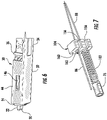
- FIG. 1 illustrates one example of a fiber optic connector 10 (also referred to as “optical connector 10", or simply “connector 10") and an adapter 12, which together represent a fiber optic connector system 14 (hereinafter "system 14").
- the connector 10 and adapter 12 will each be discussed in further detail below.
- the connector 10 is designed to have a small profile and thereby enable high-density interconnects.
- the connector 10 is particularly suitable for data centers and other environments where many connections are desired in small spaces.
- the connector 10, adapter 12, and system 14 may even be referred to respectively as the "DC connector,” “DC adapter,” and “DC connector system.”
- the connector 10 includes first and second ferrules 20, 22, an inner connector body 24 having a front end 26 from which the first and second ferrules extend, a latch arm 28 extending outwardly from the inner connector body 24, and a handle 30 that cooperates with the inner connector body 24 and latch arm 28.
- the handle 30 includes a housing portion 32 in which the inner connector body 24 is received and a grip portion 34 extending rearwardly from the housing portion 32. As will be described in greater detail below, the handle 30 can move relative to the inner connector body 24 so that the housing portion 32 can cause the latch arm 28 to flex toward the inner connector body 24.
- the connector 10 also includes an outer connector body 36 coupled to the inner connector body 24 within the housing portion 32 of the handle 30.
- a boot 38 is coupled to the outer connector body 36 outside of the housing portion 32.
- the connector 10 is shown as being mounted on a cable 40, thereby forming a cable assembly.
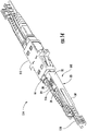
- Fig. 2 is an exploded view of the connector 10 that illustrates the above-mentioned components in further detail, along with components of the connector 10 that cannot be seen in Fig. 1 .
- the housing portion 32 of the handle 30 is in the form of a tubular body having a rectangular profile defined by sides 44 that are 90 degrees (or approximately 90 degrees) relative to each other.
- the sides 44 extend from a front opening 46 to a rear opening (not shown in Fig. 2 ) of the housing portion 32 so that the housing portion 32 has an internal cavity 50 ( Fig. 3 ) defined by the sides 44.
- Three of the sides 44 each include a tab 52 located in the front opening 46.
- one of the sides 44 includes an opening 54 for through which the latch arm 28 extends when the inner connector body 24 is received in the housing portion 32 (see Fig. 1 ).
- the grip portion 34 of the handle 30 in the embodiment shown is in the form of a plate-like extension.
- the grip portion 34 may even extend in a plane parallel (or approximately parallel) to one of the sides 44, effectively acting like an extension of that side in a rearward direction.
- the housing portion 32 and grip portion 34 may be integrally formed as a monolithic structure.
- the handle 30 may be formed from metal that has been worked or otherwise processed into shape (e.g., punched, stamped, bent, etc.).
- the handle 30 may be formed from plastic by way of molding.
- the handle 30 need not even be a monolithic structure if desired, with the housing portion 32 and grip portion 34 formed as separate components that are coupled together.
- the connector 10 further includes an outer spring 60 received over a portion of the inner connector body 24 within the housing portion 32 of the handle 30.
- the inner connector body 24 includes a back end 62 opposite the front end 26 and a flange 64 positioned between the front and back ends 26, 62.
- the flange 64 defines a forward-facing spring seat 66, and a front portion 68 of the inner connector body 24 extends from the spring seat 66 to the front end 26 of the inner connector body 24.
- the outer spring 60 is received over the front portion 68 when the connector 10 is assembled and is covered by the housing portion 32 of the handle 30.
- the outer spring 60 extends between the spring seat 66 of the flange 64 and the tabs 52 on the housing portion 32.
- the flange 64 is positioned between not only the front and back ends 26, 62 of the inner connector body 24, but also between the front end 26 and the latch arm 28. This is due to the latch arm 28 extending outwardly from the inner connector body 24 at or behind the flange 64.
- the latch arm 28 may be integrally formed with the inner connector body 24 (e.g., as a monolithic structure), as shown.
- the inner connector body 24 also includes a back portion 70 extending from the flange 64 to the back end 62. Although an internal cavity 72 extends within the inner connector body 24 between the front end 26 and back end 62, internal geometry (not shown in Fig. 2 ) prevents components that hold the first and second ferrules 20, 22 from being inserted through inner connector body 24 when the connector 10 is assembled.
- first and second ferrules 20, 22 are respectively received in first and second ferrule holders 74, 76 that have larger diameters or widths than the first and second ferrules 20, 22.
- An internal wall 78 ( Fig. 3 ) within the inner connector body 24 includes openings 80 that accommodate the first and second ferrules 20, 22, but not the first and second ferrule holders 74, 76.
- the first and second ferrules 20, 22 can be inserted through the back opening of the inner connector body 24, moved forward in the internal cavity 72, and extended through the openings 80 until the first and second ferrule holders 74, 76 contact the internal wall 78.
- the first and second ferrules 20, 22 extend beyond the front end 62 of the inner connector body 24 at this point.
- a dust cap 82 may be inserted into the font end 62 of the inner connector body 24 and received over the first and second ferrule 20, 22 when the connector 10 is not in use.
- the first and second ferrules 20, 22 are arranged to extend parallel to each other in a ferrule plane. More specifically, the first and second ferrules 20, 22 include respective first and second longitudinal axes FA1, FA2 along which the first and second ferrules extend 20, 22.
- the first and second ferrules 20, 22 in the embodiment shown are cylindrical, and the first and second longitudinal axes FA1, FA2 each represent a central axis of the corresponding ferrule.
- the first and second ferrules 20, 22 are arranged so that the first and second longitudinal axes FA1, FA2 are parallel and thereby define the ferrule plane.
- the cable 40 includes first and second optical fibers 86, 88 extending into bores 90 of the respective first and second ferrules 20, 22.
- Each bore 90 extends between a front end 92 and back end 94 of the corresponding ferrule and is aligned or approximately aligned (e.g., to within an acceptable tolerance) with the corresponding longitudinal axis (F A1 or F A2 ).
- the first and second optical fibers 86, 88 are secured in the bores 90 using an adhesive.
- the connector 10 further includes first and second inner springs 100, 102 for biasing the respective first and second ferrules 20, 22 toward the front end 26 of the inner connector body 24.
- the first and second inner springs 100, 102 each extend between one of the first and second ferrule holders 74, 76 and a spring push 104 that is received in the outer connector body 36 when the connector 10 is assembled. Additional details related to the spring push 104 and assembly of the connector 10 in general will be described in greater detail below. It can be appreciated from Figs.
- the outer connector body 36 may be coupled to the inner connector body 24 in any suitable manner.
- the outer connector body 36 is designed to be snapped onto the back portion 70 of the inner connector body 24. Latching features in the form of ramps or shoulders 106 are provided on the back portion 70 of the inner connector body 24.
- the outer connector body 36 is designed to receive the back portion 70 and includes openings 108 that cooperate with the shoulders 106 to couple the inner connector body 24 to the outer connector body 36. In other words, the outer connector body 36 can be inserted over the back portion 70, flexing as needed to accommodate the shoulders 106, until the shoulders 106 are received in or otherwise engage the openings 108.
- the outer connector body 36 flexes (e.g., snaps) back towards an unflexed shape.
- the shoulders 106 are designed so that the outer connector body 36 cannot easily be pulled back over the shoulders 106 and off the back portion 70 of the inner connector body 24.
- Figs. 2 and 3 illustrate a crimp body 110 extending rearwardly from the outer connector body 36.
- the crimp body 100 in this example embodiment is a separate component that may be coupled to the outer connector body 36 by any suitable method.
- the crimp body 110 may be a metal sleeve coupled to the outer connector body 36 by inserting molding techniques.
- the crimp body 110 may be formed integrally with the outer connector body 36 as a monolithic structure.
- strength members e.g., aramid yarn
- a heat shrink tube 116 is also provided to help further secure the cable 40 to the connector 10.
- the boot 38 extends over the heat shrink tube 116 and crimp tube 114 to abut the outer connector body 36 when the connector 10 is assembled.
- Fig. 4 is an enlarged perspective view showing only the inner connector body 24
- Fig. 5 is an enlarged perspective view of the portion of the assembled connector 10 including the inner connector body 24 and housing portion 32 of the handle 30.
- the inner connector body 24 in the embodiment shown is a generally rectangular body and can generally be considered to have four noticeable sides 120 (120a-120d).
- a rectangular profile is schematically illustrated in Fig. 4 to better illustrate how the inner connector body 24 can be considered to have the four sides 120.
- Two of the sides 120 (120b, 120d) are generally parallel to the ferrule plane, and two of the sides 120 (120a, 120c) are generally perpendicular to the ferrule plane.
- the latch arm 28 extends from one of the sides 120 perpendicular to the ferrule plane and itself intersects the ferrule plane.
- the latch arm 28 includes a ramp 124 "nestled” or otherwise positioned between first and second latching features 126, 128.
- a portion of the latch arm 28 defining the ramp 124 extends from the inner connector body 24 in an arcuate manner, thereby providing the ramp 124 with an arcuate shape in the example embodiment shown.
- the latch arm 28 includes a lower side 130 facing the inner connector body 24 and an upper side 132 opposite the lower side 130 (e.g., facing away from the inner connector body 24).
- a portion of the upper side 132 extends outwardly from the inner connector body 24 in an arcuate manner and defines the ramp 124.
- Other portions of the upper side 132 extend outwardly from the inner connector body 24 in a generally linear manner to the first and second latching features 126, 128.
- the first and second latching 126, 128 features are spaced apart from each other in a transverse direction (i.e., a direction transverse to a longitudinal axis A1).
- the ramp 124 is positioned between the first and second latching features 126, 128 in the transverse direction.
- the first and second latching features 126, 128 are spaced further from the inner connector body 24 than at least a portion of the ramp 124. This is due to the latch arm 28 also extending in the longitudinal direction as it extends outwardly from the inner connector body 24.
- the first and second latching features 126, 128 in the embodiment shown are in the form of shoulders that define rearward-facing surfaces 136.
- the shoulders cooperate with openings 140 in the adapter 12 ( Fig. 1 ) to retain the connector 10 in the adapter 12, as will be more apparent after further discussing the adapter below.
- the latch arm 28 continues to extend beyond the first and second latching features 126, 128.
- the latch arm 28 includes a terminal end 138 spaced from the first and second latching features 126, 128.
- the extension of the latch arm 28 beyond the first and second latching features 126, 128 does not increase the footprint of the inner connector body 24 in a plane perpendicular to the longitudinal axis A1.
- the extent to which the latch arm 28 extends outwardly as it extends rearwardly beyond the first and second latching features 126, 128 is limited; in some embodiments there may not even be any further extension outwardly.
- the latch arm 28 is therefore shaped such that the first and second latching features 126, 128 (or at least portions thereof) are spaced further from the inner connector body 24 than the terminal end 138.
- first and second latching features 126, 128 are provided as the first and second latching features 126, 128 in the embodiment shown, in alternative embodiments there may be a single latching feature or more than two latching features included on the latch arm.
- the latching features 128 may be formed as structures other than shoulders, as the exact form will depend on the corresponding latching features 140 of the adapter 12.
- the housing portion 32 of the handle 30 includes an opening 54 for through which the latch arm 28 extends when the connector 10 is assembled.
- the housing portion 32 also includes a pushing feature 142 adjacent the opening 54 for contacting the latch arm 24.
- the pushing feature 142 is in the form of a finger extending into the opening 54. The finger is bent back to define a rounded surface 144, as best seen in Fig. 3 .
- the pushing feature 142 may be a different type of projection with a rounded surface, or may not include any rounded surface, yet still be capable of contacting the latch arm 28 and causing the latch arm 28 to flex toward the inner connector body 24.
- the connector 10 is designed so that pushing feature 142 does not extend past the terminal end 138 of the latch arm 28 when the handle 30 has reached a rearward limit of its movement relative to the inner connector body 24. Such a design helps prevent the latch arm 28 from catching or otherwise blocking the handle 30 from moving back toward an initial position.
- the terminal end 138 of the latch arm 28 does not engage the pushing feature 142 in a manner that might prevent the handle 30 moving forwardly relative to the inner connector body 24. Instead, the pushing feature 142 is able to slide back down the ramp 124 and allow such forward movement.
- the outer spring 60 may apply a biasing force that causes the forward movement of the handle 30.
- the forward movement may be limited in a variety ways.
- the housing portion 32 further includes a stop feature in the form of a finger 146 on the side 44 opposite the opening 54. This can be better appreciated with reference to both Figs. 3 and 6 .
- the finger 146 extends in a forward direction and inwardly toward the inner connector body 24. Additionally, the finger 146 is positioned rearward of the flange 64 on the inner connector body 24. When the handle 30 is moved forwardly relative to the inner connector body 24, eventually a terminal end 148 of the finger 146 contacts the flange 64 to prevent further forward movement of the handle 30.
- the stop member may be a structure other than a finger.
- a stop member that limits forward movement of the handle 30 may be provide elsewhere on the housing portion 32 so as to cooperate with a different side 120 of the inner connector body 24.
- two of the sides 120 (120b, 120d) of the inner connector body 24 each include a guide channel 152 extending along a length of the front portion 68.
- the guide channels 152 extend between the front end 26 and the flange 64.
- the tabs 52 are in the form of lips or plate-like extensions from the sides 44 into the front opening 46 of the housing portion 32.
- the housing portion 32 may include other forms of projections received in the guide channels 152 and/or contacting the inner connector body 24.
- the projections in such embodiments may cooperate with the outer spring 60 in a manner similar to that described above with respect to the tabs 52. That is, the projections may help retain the outer spring 60 on the inner connector body 24, effectively providing a spring seat so that the outer spring 60 is able to bias the handle 30 relative to the inner connector body 24.
- the spring push 104 includes first and second slots 156, 158 for accommodating the first and second optical fibers 86, 88.
- the first and second slots 156, 158 extend from the same side of the spring push 104 such that the spring push 104 has an E-shaped configuration.
- the spring push 104 is also a generally rectangular body in the embodiment shown, making the E-shaped configuration especially apparent.
- a front side 160 of the spring push 104 defines first and second spring seats 162, 164 for positioning the respective first and second inner springs 100, 102.
- a forward-facing surface of the spring push includes first and second bumps 162, 164.
- the first and second slots 156, 158 extend into the first and second bumps 162, 164 such that the first and second optical fibers 86, 88 can extend through the first and second bumps 162, 164.
- Respective ends of the first and second inner springs 100, 102 are received over the first and second bumps 162, 164 so that the ends are maintained in position on the spring push 104.
- the front side 160 of the spring push 104 may include recesses or other structures to define the first and second spring seats.
- the outer connector body 36 includes an internal cavity 170 that receives the spring push 104 when the connector 10 is assembled.
- the internal cavity 170 is shaped so that a rearward-facing surface 166 of the spring push 104 contacts an inner wall 172 of the outer connector body 36. More specifically, the internal cavity 170 comprises a passageway though the outer connector body 36.
- a first section 174 of the passageway accommodates the spring push 104, and then steps down in diameter to define the inner wall 172. From this point, a transition section 176 of the passageway transitions to a second section 178 that has a smaller diameter than the first section 174.
- the first and second slots 156, 158 of the spring push 104 can be kept relatively small to help position the first and second optical fibers 86, 88 on or close to the longitudinal axes F A1, F A2 of the first and second ferrules 20, 22. Furthermore, because of the first and second slots 156, 158, the spring push 104 can be positioned onto the first and second optical fibers 86, 88 after installing the first and second ferrules 20, 22. Indeed, this is one aspect that facilitates assembling the connector 10 after forming sub-assemblies with the first and second ferrules 20, 22 and first and second optical fibers 86, 88.
- An assembly process may, for example, involve placing the boot 38, heat shrink tube 116, crimp tube 114, and outer connector body 36 onto the cable 40.
- the end of the cable 40 may then be prepared to form the cable assembly. This may include stripping coating(s) from specified lengths of the first and second optical fibers 86, 88, cutting strength members (e.g., aramid yarn) of the cable 40 to a desired length, etc.
- the first and second inner springs 100, 102 may be placed over the first and second optical fibers 86, 88, which may then be inserted into and secured to the first and second ferrules 20, 22.
- the first and second ferrule holders 74, 76 may already be secured to the first and second ferrules 20, 22 at this point.
- the first and second ferrules 20, 22 may be polished or otherwise processed. Because the inner connector body 24 and handle 30 have not yet been installed, the first and second ferrules 20, 22 can be accessed and handled with greater ease compared to when the connector 10 is fully assembled.
- the spring push 104 may be positioned onto the first and second optical fibers 86, 88 at a location behind the first and second inner springs 100, 102.
- the first and second slots 156, 158 of the spring push 104 accommodate the first and second optical fibers 86, 88, as noted above.
- the outer connector body 36 may then be moved forward over the spring push 104 and coupled to inner connector body 24, which is installed onto the cable 40 from the other direction.
- the spring push 104 abuts the inner wall 172 of the outer connector body 36, the first and second inner springs 100, 102 bias the first and second ferrule holders 74, 76 against the internal wall 78 of the inner connector body 24, and the front ends 90 of the first and second ferrules 20, 22 extend past the front end 26 of the inner connector body 24.
- the cable 40 may be secured to the outer connector body 36.
- Strength members e.g., aramid yarn
- the heat shrink tube 116 may be applied over the crimp tube 114 and a portion of the cable 40, and the boot 38 may be moved forward over the heat shrink tube 116 to abut the outer connector body 36.
- the connector 10 may be part of a system 14 that also includes the adapter 12.
- Fig. 8 is an exploded perspective view of an example embodiment of the adapter 12.
- the adapter 12 includes an adapter body 180 defining ports 182 (also referred to as "receptacles") into which the connector 10 can be inserted and at least one latching feature 140 (e.g., an opening) associated with each of the ports 182.
- Two ports 182 are defined in the embodiment shown-first and second ports arranged side-by-side (i.e., adjacent to each other).
- the adapter body 180 may define a single port or more than two ports (e.g., 4 ports, 6 ports, 8 ports, etc.), which may be arranged side-by-side and/or stacked on top of each other.
- the adapter body 180 may define two or more rows of two or more ports, with the ports of one row being arranged under the ports of another row so as to be arranged in columns.
- the ports 182 define generally hollow passageways extending between first and second ends 184, 186 of the adapter body 180.
- Each port 182 has a shape that generally corresponds to the housing portion 32 of the handle 30.
- each port 182 generally has a rectangular configuration.
- the adapter body itself has a rectangular configuration, but includes a flange 188 between the first and second ends 184, 186.
- the flange 188 may be located approximately halfway between the first and second ends 184, 186.
- a first portion 190 of the adapter body 180 that is between the first end 184 and the flange 188 is configured to receive a mount plate or clip 192.
- the mount plate 192 is a generally U-shaped component configured to be received on the first portion 190.
- the mount plate 192 includes arms 194 that, together with the flange 188, may be used secure the adapter 12 to a panel, faceplate, or other wall that includes openings for the adapter body 180.
- a second portion 196 of the adapter body 182 that is between the flange 188 and second end 186 is configured to receive a reinforcement plate or clip 198.
- the reinforcement plate 198 in the embodiment shown is a generally U-shaped component configured to be received on the second portion 196.
- the reinforcement plate 198 does not include the arms 194. Such arms may not be needed because the second portion 196 may be external to the hardware or other structure two which the adapter is mounted (e.g., the structure including the panel, faceplate, wall, etc. mentioned above).
- the adapter body 182 may be generally symmetrical such that a mount plate 192 may be received on the second portion 196 and a reinforcement plate 196 may be received on the first portion 190, if desired.
- the adapter 12 further includes at least one sleeve holder 200 configured to position first and second sleeves 202, 204 in each of the ports 182.
- Two sleeve holders 200 are provided in the embodiment shown, one for each of the ports 182.
- Each sleeve holder 200 may be inserted into the corresponding port 182 and then snapped or otherwise secured in place in the adapter body 180.
- Slots 206 for receiving portions of the sleeve holders 200 are provided in the adapter body 180 for this purpose.
- the slots 206 are generally located half way between the first and second ends 184, 186, similar to the flange 188.
- the first and second sleeves 202, 204 that are positioned by the sleeve holders 200 are used to align the first and second ferrules 20, 22 of the connector 10 with similarly-shaped ferrules of a mating component (e.g., another connector), as will be apparent based on the description below.
- dust caps 208 may be inserted into the ports to prevent contaminants (e.g., dust and debris) from migrating into the first and second sleeves 202, 204.
- Figs. 9 and 10 illustrate how the connector 10 can cooperate with the adapter 12.
- an individual may use the handle 30 to insert the connector 10 into one of the ports 182 of the adapter 12.
- the latch arm 28 contacts the adapter body 180, as shown in Fig. 9 .
- the latch arm 28 then flexes toward the inner connector body 24 to allow further insertion of the housing portion 32 of the handle 30 and the inner connector body 24 into the port 182.
- the first and second sleeves 202, 204 within the port 182 receive the first and second ferrules 20, 2, that extend from the inner connector body 24.
- first and second latching features 126, 128 on the latch arm 28 engage the latching feature 140 on the adapter body 180 that is associated with the port 182, as shown in Fig. 10 .
- the latching features 140 are openings that accommodate the latching features 126, 128.
- the latch arm 28 flexes away from the inner connector body 24 when the latching features 124, 126 are aligned with the openings 140.
- the rearward-facing surfaces 136 defined by the first and second latching features 126, 128 are then in a position to engage the adapter body 180 to help retain the connector 10 in the port 182.
- the connector 10 is shown as being inserted into one of the ports 182 from the second end 186 of the adapter body 180.
- a similar connector may be inserted into the port 182 from the first end 184 of the adapter body 180.
- the first and second sleeves 202, 204 within the port 182 are used to align the ferrules of the two connectors to help establish an optical connection between the optical fibers held by the ferrules.
- the process is reversed.
- An individual may once again use the handle 30.
- the pushing feature 142 on the housing portion 32 contacts and slides along the ramp 124 of the latch arm 128.
- This results in the housing portion 32 causing the latch arm 28 to flex back toward the inner connector body 24, which in turn causes the first and second latching features 124, 126 to disengage the latching feature 140 on the adapter body 180.
- the rearward-facing surfaces 136 of the first and second latching features 126, 128 are no longer positioned to engage the adapter body 180 such that the connector 10 can be pulled back out of the port 182.
- the handle 30 cooperates with the inner connector body 24 in a unique manner and can be used to both insert and remove the connector 10 from one of the ports 182.
- the connector 10 can be designed with a small profile to enable high-density interconnects.
- the first and second ferrules 20, 22 may each have a diameter of 1.25 mm, similar to the ferrules of LC connectors.
- the ports 182, however, may have a size that does not exceed 8 mm in height and 5.3 mm in width.
- the housing portion 32 of the handle 30 and the inner connector body 24 (but for the latch arm 28) also have sizes within these dimensions, which generally correspond to the port size for a conventional LC adapter.
- the connector 10 can effectively double the density of interconnects compared to conventional LC connectors, providing two 1.25 mm-diameter ferrules in the same space as an LC connector with one 1.25 mm-diameter ferrule.
- the adapter body 180 may be sized to fit within the openings ("cutouts") of existing faceplates, panels, etc. for conventional LC duplex adapters.
- the system 14 enables twice as many optical interconnects (4 total; 2 from each connector inserted into the ports) compared to a conventional LC duplex connector system (which has 2 total optical interconnects; 1 from each LC connector sub-assembly in the LC duplex connector).
- the system 14 effectively has half the footprint size of LC connector systems and, therefore, can be used to double the density of optical interconnects compared to LC connector systems.
- Fig. 11 illustrates an example of a high-density interconnect 300 enabled by the system 14.
- the adapters 12 are mounted to an equipment rack 302, which may have conventional dimensions of 19" (482.60 mm) in width and 1.752 inches (44.50 mm) in height.
- each of the adapters 12 has a 6-port configuration.
- the adapters 12 are arranged as four rows of nine adapters, resulting in 432 ports (and, therefore, 432 potential optical interconnects; 2 per port x 6 per adapter x 9 adapters per row x 4 rows of adapters). In other words, there are 432 ports within one rack unit (i.e., "1U").
- the connector 10 may also be used with transceiver modules.
- Figs. 12 and 13 illustrate the connector 10 being inserted into a transceiver module 400.
- the transceiver module 400 includes an adapter 402 that defines first and second ports 404 like the adapter 12 (i.e., the ports 404 correspond to the ports 182).
- the connector 10 can cooperate with the adapter 402 in a manner similar to how it cooperates with the adapter 12. That is, the connector 10 can be inserted into and removed from the adapter 402 of the transceiver module 400 in a manner similar to that described above for the adapter 12 (see discussion of Figs. 9 and 10 above).
- the transceiver module 400 for the connector 10 may also be considered part of the system 14.
- Fig. 14 illustrates a fiber optic connector system 514 that includes a fiber optic connector 510 ("connector 510") and an adapter 512.
- the connector 510 and adapter 512 are generally similar to the connector 10 and adapter 12, and similar reference numbers are used to refer to corresponding elements.
- the handle 30 includes several modifications.
- the housing portion 32 includes a ledge 516 at the back end of the housing portion 30, on at least the side 44 with the opening 54.
- the ledge 516 may facilitate an individual using the housing portion 32 to push and pull the connector 10 from the adapter 512 (e.g., if the individual chooses not to use the grip portion 34). Additionally, the grip portion 34 includes a block or knob 518 that makes the grip portion 34 easier to grasp and, therefore, facilitates use of the handle 30.
Landscapes
- Physics & Mathematics (AREA)
- General Physics & Mathematics (AREA)
- Optics & Photonics (AREA)
- Mechanical Coupling Of Light Guides (AREA)
Claims (15)
- Connecteur de fibres optiques, comprenant :une première et une deuxième férule (20, 22) configurées chacune pour soutenir au moins une fibre optique (86, 88) et arrangées pour s'étendre parallèles l'une à l'autre dans un plan de férules ;un corps de connecteur interne (24) ayant une extrémité avant (26) de laquelle la première et la deuxième férule (20, 22) s'étendent ;un bras de verrouillage (28) s'étendant vers l'extérieur du corps de connecteur interne (24) ; etune poignée (30) ayant une partie de boîtier (32) dans laquelle le corps de connecteur interne (24) est au moins partiellement reçu et une partie de prise (34) s'étendant vers l'arrière de la partie de boîtier (32), dans lequel la poignée (30) peut se déplacer par rapport au corps de connecteur interne (24) de telle sorte que la partie de boîtier (32) peut faire que le bras de verrouillage (28) fléchisse vers le corps de connecteur interne (24), le connecteur de fibres optiques étant caractérisé par le bras de verrouillage (28) intersectant le plan des férules.
- Connecteur de fibres optiques selon la revendication 1, dans lequel la partie de boîtier (32) de la poignée (30) comprend un élément de poussée (142) pour entrer en contact avec le bras de verrouillage (28) pour faire que le bras de verrouillage (28) fléchisse vers le corps de connecteur interne (24), dans lequel le bras de verrouillage (28) comprend une rampe (124) le long de laquelle l'élément de poussée (142) peut glisser pour faire que le bras de verrouillage (28) fléchisse vers le corps de connecteur interne (28).
- Connecteur de fibres optiques selon la revendication 2, dans lequel l'élément de poussée (142) comprend une saillie ayant une surface arrondie (144) pour entrer en contact avec la rampe (124) sur le bras de verrouillage (28).
- Connecteur de fibres optiques selon la revendication 2 ou la revendication 3, dans lequel :le bras de verrouillage (28) comprend au moins un élément de verrouillage (126, 128) plus espacé du corps de connecteur interne qu'au moins une partie de la rampe (124) ;le bras de verrouillage (28) comprend un côté inférieur (130) faisant face au corps de connecteur interne (24) et un côté supérieur (32) opposé au côté inférieur (130) ;une première partie du côté supérieur (132) s'étend vers l'extérieur du corps de connecteur interne (24) d'une manière arquée et définit la rampe (124) ;une deuxième partie du côté supérieur (132) s'étend vers l'extérieur du corps de connecteur interne jusqu'à au moins un élément de verrouillage (126, 128) d'une manière généralement linéaire ;le corps de connecteur interne (24) s'étend le long d'un axe longitudinal ;le au moins un élément de verrouillage (126, 128) comprend un premier et un deuxième élément de verrouillage (126, 128) espacés l'un de l'autre dans une direction transversale à l'axe longitudinal ;la rampe (124) est positionnée entre le premier et le deuxième élément de verrouillage (126, 128) ;le bras de verrouillage (28) comprend en outre une extrémité terminale (138) espacée du premier et du deuxième élément de verrouillage (126, 128) ;l'extrémité terminale (138) et le premier et le deuxième élément de verrouillage (126, 128) ont des positions respectives par rapport au corps de connecteur interne (24) ; etle bras de verrouillage (28) est façonné de telle sorte que la position du premier et du deuxième élément de verrouillage (126, 128) est plus éloignée du corps de connecteur interne (124) que la position de l'extrémité terminale (138).
- Connecteur de fibres optiques selon l'une quelconque des revendications 1 à 4, dans lequel :le bras de verrouillage (128) comprend en outre au moins un élément de verrouillage (126, 128) et une extrémité terminale (138) espacée du au moins un élément de verrouillage (126, 128), le au moins un élément de verrouillage (126, 128) comprenant au moins un épaulement faisant face vers l'arrière (136) ;l'extrémité terminale (138) et le au moins un élément de verrouillage (126, 128) ont des positions respectives par rapport au corps de connecteur interne (24) ; etle bras de verrouillage (28) est façonné de telle sorte que la position du au moins un élément de verrouillage (126, 128) est plus éloignée du corps de connecteur interne (24) que la position de l'extrémité terminale (138).
- Connecteur de fibres optiques selon l'une quelconque des revendications 1 à 5, dans lequel :le corps de connecteur interne (24) comprend au moins un canal de guidage (152) s'étendant le long d'une longueur du corps de connecteur interne (24) ;la partie de boîtier (32) de la poignée (30) comprend au moins une saillie reçue dans le au moins un canal de guidage (152) ;la partie de boîtier (32) de la poignée comprend une ouverture frontale (46) à travers laquelle la première et la deuxième férule s'étendent ; etla au moins une saillie sur la partie de boîtier (32) comprend au moins une patte (52) située au niveau de l'ouverture frontale.
- Connecteur de fibres optiques selon l'une quelconque des revendications 1 à 6, comprenant en outre un ressort externe (60) reçu sur une partie du corps de connecteur interne (24), dans lequel :le ressort externe (60) pousse la partie de boîtier (32) de la poignée (30) par rapport au corps de connecteur interne (24),le corps de connecteur interne (24) comprend une bride (64) positionnée entre l'extrémité avant (26) du corps de connecteur interne (24) et le bras de verrouillage (28),la partie de boîtier (32) de la poignée (30) comprend au moins une saillie s'étendant vers le corps de connecteur interne (24), etle ressort externe (60) s'étend entre la au moins une saillie de la poignée (30) et la bride du corps de connecteur interne (24).
- Connecteur de fibres optiques selon l'une quelconque des revendications 1 à 7, dans lequel :le corps de connecteur interne (24) comprend une bride (64) positionnée entre l'extrémité avant (26) du corps de connecteur interne (24) et le bras de verrouillage (28) ;la partie de boîtier (32) de la poignée (30) comprend au moins un membre de butée s'étendant vers le corps de connecteur interne (24) ; etle au moins un membre de butée est configuré pour coopérer avec la bride pour limiter le mouvement en avant de la poignée (30) par rapport au corps de connecteur interne (24) ;le au moins un membre de butée est configuré pour coopérer avec la bride (64) sur un côté du corps de connecteur interne (24) qui est opposé au bras de verrouillage (28) ; etle au moins un membre de butée comprend un doigt s'étendant vers le corps de connecteur interne (24).
- Connecteur de fibres optiques selon l'une quelconque des revendications 1 à 8, dans lequel :
la partie de boîtier (32) de la poignée (30) comprend une ouverture (54) à travers laquelle le bras de verrouillage (28) s'étend. - Connecteur de fibres optiques selon l'une quelconque des revendications 1 à 9, dans lequel le corps de connecteur interne (24) comprend en outre une extrémité arrière (62) opposée à l'extrémité avant (26), le connecteur de fibres optiques comprenant en outre :un corps de connecteur externe (36) couplé à l'extrémité arrière (62) du corps de connecteur interne (24) ;un premier et un deuxième ressort interne (100, 102) s'étendant dans le corps de connecteur interne (24) et le corps de connecteur externe (36), dans lequel le premier et le deuxième ressort interne poussent la première et la deuxième férule (20, 22) respectives vers l'extrémité avant (26) du corps de connecteur interne (24) ; etun poussoir de ressort (104) reçu dans le corps de connecteur externe (36), dans lequel le poussoir de ressort (104) comprend une première et une deuxième fente (156, 158) pour recevoir la au moins une fibre optique (86, 88) respective que la première et la deuxième férule (20, 22) respectives sont configurées pour soutenir, et dans lequel le poussoir de ressort (104) définit une première et une deuxième assise de ressort (162, 164) pour positionner le premier et le deuxième ressort interne (100, 102) respectifs dans le corps de connecteur externe (36).
- Connecteur de fibres optiques selon la revendication 10, dans lequel :
le poussoir de ressort (104) comprend une surface orientée vers l'avant et une première et une deuxième bosses sur la surface orientée vers l'avant qui définissent la première et la deuxième assise de ressort (162, 164) respectives. - Connecteur de fibres optiques selon la revendication 10 ou la revendication 11, dans lequel le poussoir de ressort (104) a une configuration en forme de E.
- Connecteur de fibres optiques selon l'une quelconque des revendications 1 à 11, dans lequel le bras de verrouillage (28) est le seul bras de verrouillage (28) s'étendant du corps de connecteur interne (24).
- Ensemble de câble, comprenant :un câble à fibres optiques (40) comprenant une première et une deuxième fibre optique (86, 88) ; etun connecteur de fibres optiques (10) selon l'une quelconque des revendications 1 à 13 monté sur le câble à fibres optiques (40), dans lequel la première et la deuxième fibre optique (86, 88) sont soutenues par la première et la deuxième férule (20, 22) respectives du connecteur de fibres optiques (10).
- Système connecteur de fibres optiques, comprenant :un connecteur de fibres optiques (10) selon l'une quelconque des revendications 1 à 13 ; etun adaptateur (12) comprenant :un corps d'adaptateur (180) définissant un orifice (182) dans lequel le connecteur de fibres optiques (10) peut être inséré et un élément de verrouillage d'adaptateur (140) communiquant avec l'orifice (182) ; etune première et une deuxième gaine (202, 204) disposées respectivement dans le premier et le deuxième orifice (182) pour recevoir la première et la deuxième férule (20, 22) du connecteur de fibres optiques (10) lorsque le connecteur de fibres optiques (10) est inséré dans l'orifice (82),dans lequel :l'orifice (182) est configuré pour recevoir la partie de boîtier (32) de la poignée (30) du connecteur de fibres optiques (10) ; etl'élément de verrouillage d'adaptateur (140) est configuré pour être engagé par le bras de verrouillage (28) sur le corps de connecteur interne (24) du connecteur de fibres optiques (10) pour retenir le connecteur de fibres optiques (10) dans l'orifice (182).
Applications Claiming Priority (3)
| Application Number | Priority Date | Filing Date | Title |
|---|---|---|---|
| US201662388129P | 2016-01-20 | 2016-01-20 | |
| US201662398673P | 2016-09-23 | 2016-09-23 | |
| PCT/US2016/067903 WO2017127208A1 (fr) | 2016-01-20 | 2016-12-21 | Connecteur de fibre optique à profil bas, et des ensembles câbles, systèmes et procédés le comprenant |
Publications (2)
| Publication Number | Publication Date |
|---|---|
| EP3405824A1 EP3405824A1 (fr) | 2018-11-28 |
| EP3405824B1 true EP3405824B1 (fr) | 2022-05-18 |
Family
ID=57758810
Family Applications (1)
| Application Number | Title | Priority Date | Filing Date |
|---|---|---|---|
| EP16823491.2A Active EP3405824B1 (fr) | 2016-01-20 | 2016-12-21 | Connecteur de fibre optique à profil réduit, et des ensembles câbles et systèmes le comprenant |
Country Status (3)
| Country | Link |
|---|---|
| EP (1) | EP3405824B1 (fr) |
| CN (2) | CN107193087B (fr) |
| WO (1) | WO2017127208A1 (fr) |
Families Citing this family (17)
| Publication number | Priority date | Publication date | Assignee | Title |
|---|---|---|---|---|
| US9658409B2 (en) | 2015-03-03 | 2017-05-23 | Senko Advanced Components, Inc. | Optical fiber connector with changeable polarity |
| US10158194B2 (en) | 2016-01-15 | 2018-12-18 | Senko Advanced Components, Inc. | Narrow width adapters and connectors with spring loaded remote release |
| EP3405824B1 (fr) * | 2016-01-20 | 2022-05-18 | Alliance Fiber Optic Products, Inc. | Connecteur de fibre optique à profil réduit, et des ensembles câbles et systèmes le comprenant |
| US9726830B1 (en) | 2016-06-28 | 2017-08-08 | Senko Advanced Components, Inc. | Connector and adapter system for two-fiber mechanical transfer type ferrule |
| US10228521B2 (en) | 2016-12-05 | 2019-03-12 | Senko Advanced Components, Inc. | Narrow width adapters and connectors with modular latching arm |
| US11333836B2 (en) | 2017-01-30 | 2022-05-17 | Senko Advanced Components, Inc. | Adapter for optical connectors |
| US10281669B2 (en) | 2017-07-14 | 2019-05-07 | Senko Advance Components, Inc. | Ultra-small form factor optical connectors |
| US11822133B2 (en) | 2017-07-14 | 2023-11-21 | Senko Advanced Components, Inc. | Ultra-small form factor optical connector and adapter |
| US12001064B2 (en) | 2017-07-14 | 2024-06-04 | Senko Advanced Components, Inc. | Small form factor fiber optic connector with multi-purpose boot |
| CN115201974B (zh) * | 2017-12-19 | 2024-04-30 | 美国康涅克有限公司 | 具有推拉极性机构和载体的微型双工连接器 |
| US11719893B2 (en) * | 2018-04-06 | 2023-08-08 | Us Conec Ltd. | Flexible push-pull boot and crimp body for fiber optic connector |
| CN112823304B (zh) * | 2018-09-12 | 2023-09-29 | 扇港元器件股份有限公司 | 具有缆线护套释放的光纤连接器组件 |
| US11579379B2 (en) | 2019-03-28 | 2023-02-14 | Senko Advanced Components, Inc. | Fiber optic adapter assembly |
| CN113966479B (zh) * | 2019-05-16 | 2024-05-24 | 扇港元器件有限公司 | 墙后式光连接器以及其组件 |
| CN110824628B (zh) | 2019-12-19 | 2021-12-07 | 武汉邮埃服光电科技有限公司 | 一种光纤连接器及其组件 |
| CN111239920B (zh) * | 2020-03-12 | 2024-12-17 | 深圳市夏裕精密部件有限公司 | Lc光纤连接器 |
| WO2022098600A1 (fr) * | 2020-11-05 | 2022-05-12 | Corning Research & Development Corporation | Connecteurs de fibres optiques ayant un corps de retenue interne |
Citations (2)
| Publication number | Priority date | Publication date | Assignee | Title |
|---|---|---|---|---|
| JPH0425807A (ja) * | 1990-05-21 | 1992-01-29 | Nec Corp | 光コネクタ |
| EP1065756A2 (fr) * | 1999-06-29 | 2001-01-03 | Nec Corporation | Mécanisme de verrouillage/déverrouillage pour connecteur de câble et procédé de verrouillage/déverrouillage |
Family Cites Families (9)
| Publication number | Priority date | Publication date | Assignee | Title |
|---|---|---|---|---|
| US5076656A (en) * | 1984-06-08 | 1991-12-31 | Briggs Robert C | High precision optical fiber connectors |
| JP2000081541A (ja) * | 1998-06-29 | 2000-03-21 | Yazaki Corp | 光ファイバコネクタ |
| JP3869411B2 (ja) * | 2003-12-11 | 2007-01-17 | 日本航空電子工業株式会社 | 光コネクタのロック解除装置 |
| US8231283B2 (en) * | 2010-12-06 | 2012-07-31 | Hon Hai Precision Ind. Co., Ltd. | Waveguide connector with improved structure for positioning waveguide into ferrule |
| CN104718480B (zh) * | 2012-09-12 | 2018-02-09 | 3M创新有限公司 | 远程夹持多光纤连接器 |
| US9207410B2 (en) * | 2013-12-23 | 2015-12-08 | Alliance Fiber Optic Products, Inc. | Optical fiber connector assembly |
| JP2015200771A (ja) * | 2014-04-08 | 2015-11-12 | 三和電気工業株式会社 | Lc型光コネクタプラグ |
| CN204595258U (zh) * | 2015-04-20 | 2015-08-26 | 连展科技电子(昆山)有限公司 | 可快速解锁的光纤插头连接器 |
| EP3405824B1 (fr) * | 2016-01-20 | 2022-05-18 | Alliance Fiber Optic Products, Inc. | Connecteur de fibre optique à profil réduit, et des ensembles câbles et systèmes le comprenant |
-
2016
- 2016-12-21 EP EP16823491.2A patent/EP3405824B1/fr active Active
- 2016-12-21 WO PCT/US2016/067903 patent/WO2017127208A1/fr not_active Ceased
-
2017
- 2017-01-20 CN CN201710044969.2A patent/CN107193087B/zh not_active Expired - Fee Related
- 2017-01-20 CN CN201720078918.7U patent/CN207008118U/zh not_active Expired - Fee Related
Patent Citations (2)
| Publication number | Priority date | Publication date | Assignee | Title |
|---|---|---|---|---|
| JPH0425807A (ja) * | 1990-05-21 | 1992-01-29 | Nec Corp | 光コネクタ |
| EP1065756A2 (fr) * | 1999-06-29 | 2001-01-03 | Nec Corporation | Mécanisme de verrouillage/déverrouillage pour connecteur de câble et procédé de verrouillage/déverrouillage |
Also Published As
| Publication number | Publication date |
|---|---|
| WO2017127208A1 (fr) | 2017-07-27 |
| CN207008118U (zh) | 2018-02-13 |
| CN107193087A (zh) | 2017-09-22 |
| EP3405824A1 (fr) | 2018-11-28 |
| CN107193087B (zh) | 2020-06-09 |
Similar Documents
| Publication | Publication Date | Title |
|---|---|---|
| EP3405824B1 (fr) | Connecteur de fibre optique à profil réduit, et des ensembles câbles et systèmes le comprenant | |
| US10191227B2 (en) | Fiber optic connector with small profile, and cable assemblies, systems, and methods including the same | |
| KR102239204B1 (ko) | 모듈형 래칭 아암을 갖는 좁은 폭 어댑터 및 커넥터 | |
| EP3414608B1 (fr) | Connecteur de fibres optiques à ferrules multifibres, et ensembles de câbles et systèmes en comportant | |
| US11500164B2 (en) | LC type connector with push/pull assembly for releasing connector from a receptacle using a cable boot | |
| EP3407105B1 (fr) | Bloc adaptateur à fibre optique | |
| EP3682277B1 (fr) | Connecteur pour fibres optiques à libération intégrée à la tétine | |
| EP0156397A2 (fr) | Connecteur fibre-optique | |
| US20120141070A1 (en) | Connector assembly with improved structure on a bracket for mounting connectors | |
| CN112292230A (zh) | 用于从适配器接口移除多个微型光学连接器的移除工具 | |
| US11320600B2 (en) | Fiber optic connector for hardware interiors and method of using same | |
| US10180539B2 (en) | Field-installable fiber optic connectors and related cable assemblies | |
| US11092760B2 (en) | Anti-jam alignment sleeve holder or connector housing for a ferrule assembly | |
| KR20130004236U (ko) | 상보적인 짝맞춤 형상부를 갖는 페룰 및 관련 섬유 광학 컨넥터 | |
| CN112731596A (zh) | 具有模块化闩锁臂的窄宽度适配器和连接器 | |
| CN119234169A (zh) | 被配置为在被推动通过管道之后现场组装的多光纤推入式(mpo)连接器 | |
| US11086087B2 (en) | LC type connector with clip-on push/pull tab for releasing connector from a receptacle using a cable boot | |
| WO2006029299A2 (fr) | Systeme de connexion optique comprenant une ferrule de type mt de taille reduite | |
| WO2022081547A1 (fr) | Système de connexion à fibres multiples | |
| KR20130002936U (ko) | 상보적인 짝맞춤 형상부를 갖는 페룰 및 관련 섬유 광학 컨넥터 | |
| CN113966479A (zh) | 墙后式光连接器以及其组件 | |
| US20130259433A1 (en) | Field-installable fiber optic connectors and related cable assemblies |
Legal Events
| Date | Code | Title | Description |
|---|---|---|---|
| STAA | Information on the status of an ep patent application or granted ep patent |
Free format text: STATUS: UNKNOWN |
|
| STAA | Information on the status of an ep patent application or granted ep patent |
Free format text: STATUS: THE INTERNATIONAL PUBLICATION HAS BEEN MADE |
|
| PUAI | Public reference made under article 153(3) epc to a published international application that has entered the european phase |
Free format text: ORIGINAL CODE: 0009012 |
|
| STAA | Information on the status of an ep patent application or granted ep patent |
Free format text: STATUS: REQUEST FOR EXAMINATION WAS MADE |
|
| 17P | Request for examination filed |
Effective date: 20180727 |
|
| AK | Designated contracting states |
Kind code of ref document: A1 Designated state(s): AL AT BE BG CH CY CZ DE DK EE ES FI FR GB GR HR HU IE IS IT LI LT LU LV MC MK MT NL NO PL PT RO RS SE SI SK SM TR |
|
| AX | Request for extension of the european patent |
Extension state: BA ME |
|
| DAV | Request for validation of the european patent (deleted) | ||
| DAX | Request for extension of the european patent (deleted) | ||
| GRAP | Despatch of communication of intention to grant a patent |
Free format text: ORIGINAL CODE: EPIDOSNIGR1 |
|
| STAA | Information on the status of an ep patent application or granted ep patent |
Free format text: STATUS: GRANT OF PATENT IS INTENDED |
|
| INTG | Intention to grant announced |
Effective date: 20211208 |
|
| GRAS | Grant fee paid |
Free format text: ORIGINAL CODE: EPIDOSNIGR3 |
|
| GRAA | (expected) grant |
Free format text: ORIGINAL CODE: 0009210 |
|
| STAA | Information on the status of an ep patent application or granted ep patent |
Free format text: STATUS: THE PATENT HAS BEEN GRANTED |
|
| AK | Designated contracting states |
Kind code of ref document: B1 Designated state(s): AL AT BE BG CH CY CZ DE DK EE ES FI FR GB GR HR HU IE IS IT LI LT LU LV MC MK MT NL NO PL PT RO RS SE SI SK SM TR |
|
| REG | Reference to a national code |
Ref country code: GB Ref legal event code: FG4D |
|
| REG | Reference to a national code |
Ref country code: CH Ref legal event code: EP |
|
| REG | Reference to a national code |
Ref country code: IE Ref legal event code: FG4D |
|
| REG | Reference to a national code |
Ref country code: DE Ref legal event code: R096 Ref document number: 602016072282 Country of ref document: DE |
|
| REG | Reference to a national code |
Ref country code: AT Ref legal event code: REF Ref document number: 1493487 Country of ref document: AT Kind code of ref document: T Effective date: 20220615 |
|
| REG | Reference to a national code |
Ref country code: NL Ref legal event code: FP |
|
| REG | Reference to a national code |
Ref country code: LT Ref legal event code: MG9D |
|
| REG | Reference to a national code |
Ref country code: AT Ref legal event code: MK05 Ref document number: 1493487 Country of ref document: AT Kind code of ref document: T Effective date: 20220518 |
|
| PG25 | Lapsed in a contracting state [announced via postgrant information from national office to epo] |
Ref country code: SE Free format text: LAPSE BECAUSE OF FAILURE TO SUBMIT A TRANSLATION OF THE DESCRIPTION OR TO PAY THE FEE WITHIN THE PRESCRIBED TIME-LIMIT Effective date: 20220518 Ref country code: PT Free format text: LAPSE BECAUSE OF FAILURE TO SUBMIT A TRANSLATION OF THE DESCRIPTION OR TO PAY THE FEE WITHIN THE PRESCRIBED TIME-LIMIT Effective date: 20220919 Ref country code: NO Free format text: LAPSE BECAUSE OF FAILURE TO SUBMIT A TRANSLATION OF THE DESCRIPTION OR TO PAY THE FEE WITHIN THE PRESCRIBED TIME-LIMIT Effective date: 20220818 Ref country code: LT Free format text: LAPSE BECAUSE OF FAILURE TO SUBMIT A TRANSLATION OF THE DESCRIPTION OR TO PAY THE FEE WITHIN THE PRESCRIBED TIME-LIMIT Effective date: 20220518 Ref country code: HR Free format text: LAPSE BECAUSE OF FAILURE TO SUBMIT A TRANSLATION OF THE DESCRIPTION OR TO PAY THE FEE WITHIN THE PRESCRIBED TIME-LIMIT Effective date: 20220518 Ref country code: GR Free format text: LAPSE BECAUSE OF FAILURE TO SUBMIT A TRANSLATION OF THE DESCRIPTION OR TO PAY THE FEE WITHIN THE PRESCRIBED TIME-LIMIT Effective date: 20220819 Ref country code: FI Free format text: LAPSE BECAUSE OF FAILURE TO SUBMIT A TRANSLATION OF THE DESCRIPTION OR TO PAY THE FEE WITHIN THE PRESCRIBED TIME-LIMIT Effective date: 20220518 Ref country code: ES Free format text: LAPSE BECAUSE OF FAILURE TO SUBMIT A TRANSLATION OF THE DESCRIPTION OR TO PAY THE FEE WITHIN THE PRESCRIBED TIME-LIMIT Effective date: 20220518 Ref country code: BG Free format text: LAPSE BECAUSE OF FAILURE TO SUBMIT A TRANSLATION OF THE DESCRIPTION OR TO PAY THE FEE WITHIN THE PRESCRIBED TIME-LIMIT Effective date: 20220818 Ref country code: AT Free format text: LAPSE BECAUSE OF FAILURE TO SUBMIT A TRANSLATION OF THE DESCRIPTION OR TO PAY THE FEE WITHIN THE PRESCRIBED TIME-LIMIT Effective date: 20220518 |
|
| PG25 | Lapsed in a contracting state [announced via postgrant information from national office to epo] |
Ref country code: RS Free format text: LAPSE BECAUSE OF FAILURE TO SUBMIT A TRANSLATION OF THE DESCRIPTION OR TO PAY THE FEE WITHIN THE PRESCRIBED TIME-LIMIT Effective date: 20220518 Ref country code: PL Free format text: LAPSE BECAUSE OF FAILURE TO SUBMIT A TRANSLATION OF THE DESCRIPTION OR TO PAY THE FEE WITHIN THE PRESCRIBED TIME-LIMIT Effective date: 20220518 Ref country code: LV Free format text: LAPSE BECAUSE OF FAILURE TO SUBMIT A TRANSLATION OF THE DESCRIPTION OR TO PAY THE FEE WITHIN THE PRESCRIBED TIME-LIMIT Effective date: 20220518 Ref country code: IS Free format text: LAPSE BECAUSE OF FAILURE TO SUBMIT A TRANSLATION OF THE DESCRIPTION OR TO PAY THE FEE WITHIN THE PRESCRIBED TIME-LIMIT Effective date: 20220918 |
|
| PG25 | Lapsed in a contracting state [announced via postgrant information from national office to epo] |
Ref country code: SM Free format text: LAPSE BECAUSE OF FAILURE TO SUBMIT A TRANSLATION OF THE DESCRIPTION OR TO PAY THE FEE WITHIN THE PRESCRIBED TIME-LIMIT Effective date: 20220518 Ref country code: SK Free format text: LAPSE BECAUSE OF FAILURE TO SUBMIT A TRANSLATION OF THE DESCRIPTION OR TO PAY THE FEE WITHIN THE PRESCRIBED TIME-LIMIT Effective date: 20220518 Ref country code: RO Free format text: LAPSE BECAUSE OF FAILURE TO SUBMIT A TRANSLATION OF THE DESCRIPTION OR TO PAY THE FEE WITHIN THE PRESCRIBED TIME-LIMIT Effective date: 20220518 Ref country code: EE Free format text: LAPSE BECAUSE OF FAILURE TO SUBMIT A TRANSLATION OF THE DESCRIPTION OR TO PAY THE FEE WITHIN THE PRESCRIBED TIME-LIMIT Effective date: 20220518 Ref country code: DK Free format text: LAPSE BECAUSE OF FAILURE TO SUBMIT A TRANSLATION OF THE DESCRIPTION OR TO PAY THE FEE WITHIN THE PRESCRIBED TIME-LIMIT Effective date: 20220518 Ref country code: CZ Free format text: LAPSE BECAUSE OF FAILURE TO SUBMIT A TRANSLATION OF THE DESCRIPTION OR TO PAY THE FEE WITHIN THE PRESCRIBED TIME-LIMIT Effective date: 20220518 |
|
| REG | Reference to a national code |
Ref country code: DE Ref legal event code: R097 Ref document number: 602016072282 Country of ref document: DE |
|
| PLBE | No opposition filed within time limit |
Free format text: ORIGINAL CODE: 0009261 |
|
| STAA | Information on the status of an ep patent application or granted ep patent |
Free format text: STATUS: NO OPPOSITION FILED WITHIN TIME LIMIT |
|
| PG25 | Lapsed in a contracting state [announced via postgrant information from national office to epo] |
Ref country code: AL Free format text: LAPSE BECAUSE OF FAILURE TO SUBMIT A TRANSLATION OF THE DESCRIPTION OR TO PAY THE FEE WITHIN THE PRESCRIBED TIME-LIMIT Effective date: 20220518 |
|
| 26N | No opposition filed |
Effective date: 20230221 |
|
| PG25 | Lapsed in a contracting state [announced via postgrant information from national office to epo] |
Ref country code: SI Free format text: LAPSE BECAUSE OF FAILURE TO SUBMIT A TRANSLATION OF THE DESCRIPTION OR TO PAY THE FEE WITHIN THE PRESCRIBED TIME-LIMIT Effective date: 20220518 |
|
| REG | Reference to a national code |
Ref country code: CH Ref legal event code: PL |
|
| REG | Reference to a national code |
Ref country code: BE Ref legal event code: MM Effective date: 20221231 |
|
| PG25 | Lapsed in a contracting state [announced via postgrant information from national office to epo] |
Ref country code: LU Free format text: LAPSE BECAUSE OF NON-PAYMENT OF DUE FEES Effective date: 20221221 |
|
| PG25 | Lapsed in a contracting state [announced via postgrant information from national office to epo] |
Ref country code: LI Free format text: LAPSE BECAUSE OF NON-PAYMENT OF DUE FEES Effective date: 20221231 Ref country code: IE Free format text: LAPSE BECAUSE OF NON-PAYMENT OF DUE FEES Effective date: 20221221 Ref country code: CH Free format text: LAPSE BECAUSE OF NON-PAYMENT OF DUE FEES Effective date: 20221231 |
|
| PG25 | Lapsed in a contracting state [announced via postgrant information from national office to epo] |
Ref country code: FR Free format text: LAPSE BECAUSE OF NON-PAYMENT OF DUE FEES Effective date: 20221231 Ref country code: BE Free format text: LAPSE BECAUSE OF NON-PAYMENT OF DUE FEES Effective date: 20221231 |
|
| PG25 | Lapsed in a contracting state [announced via postgrant information from national office to epo] |
Ref country code: IT Free format text: LAPSE BECAUSE OF FAILURE TO SUBMIT A TRANSLATION OF THE DESCRIPTION OR TO PAY THE FEE WITHIN THE PRESCRIBED TIME-LIMIT Effective date: 20220518 |
|
| PG25 | Lapsed in a contracting state [announced via postgrant information from national office to epo] |
Ref country code: HU Free format text: LAPSE BECAUSE OF FAILURE TO SUBMIT A TRANSLATION OF THE DESCRIPTION OR TO PAY THE FEE WITHIN THE PRESCRIBED TIME-LIMIT; INVALID AB INITIO Effective date: 20161221 |
|
| PG25 | Lapsed in a contracting state [announced via postgrant information from national office to epo] |
Ref country code: CY Free format text: LAPSE BECAUSE OF FAILURE TO SUBMIT A TRANSLATION OF THE DESCRIPTION OR TO PAY THE FEE WITHIN THE PRESCRIBED TIME-LIMIT Effective date: 20220511 |
|
| PG25 | Lapsed in a contracting state [announced via postgrant information from national office to epo] |
Ref country code: MK Free format text: LAPSE BECAUSE OF FAILURE TO SUBMIT A TRANSLATION OF THE DESCRIPTION OR TO PAY THE FEE WITHIN THE PRESCRIBED TIME-LIMIT Effective date: 20220511 |
|
| PG25 | Lapsed in a contracting state [announced via postgrant information from national office to epo] |
Ref country code: MC Free format text: LAPSE BECAUSE OF FAILURE TO SUBMIT A TRANSLATION OF THE DESCRIPTION OR TO PAY THE FEE WITHIN THE PRESCRIBED TIME-LIMIT Effective date: 20220518 |
|
| PG25 | Lapsed in a contracting state [announced via postgrant information from national office to epo] |
Ref country code: TR Free format text: LAPSE BECAUSE OF FAILURE TO SUBMIT A TRANSLATION OF THE DESCRIPTION OR TO PAY THE FEE WITHIN THE PRESCRIBED TIME-LIMIT Effective date: 20220511 Ref country code: MC Free format text: LAPSE BECAUSE OF FAILURE TO SUBMIT A TRANSLATION OF THE DESCRIPTION OR TO PAY THE FEE WITHIN THE PRESCRIBED TIME-LIMIT Effective date: 20220518 |
|
| PG25 | Lapsed in a contracting state [announced via postgrant information from national office to epo] |
Ref country code: MT Free format text: LAPSE BECAUSE OF FAILURE TO SUBMIT A TRANSLATION OF THE DESCRIPTION OR TO PAY THE FEE WITHIN THE PRESCRIBED TIME-LIMIT Effective date: 20220511 |
|
| PG25 | Lapsed in a contracting state [announced via postgrant information from national office to epo] |
Ref country code: BG Free format text: LAPSE BECAUSE OF FAILURE TO SUBMIT A TRANSLATION OF THE DESCRIPTION OR TO PAY THE FEE WITHIN THE PRESCRIBED TIME-LIMIT Effective date: 20220518 |
|
| PG25 | Lapsed in a contracting state [announced via postgrant information from national office to epo] |
Ref country code: BG Free format text: LAPSE BECAUSE OF FAILURE TO SUBMIT A TRANSLATION OF THE DESCRIPTION OR TO PAY THE FEE WITHIN THE PRESCRIBED TIME-LIMIT Effective date: 20220518 |
|
| PGFP | Annual fee paid to national office [announced via postgrant information from national office to epo] |
Ref country code: NL Payment date: 20241114 Year of fee payment: 9 |
|
| PGFP | Annual fee paid to national office [announced via postgrant information from national office to epo] |
Ref country code: DE Payment date: 20241111 Year of fee payment: 9 |
|
| PGFP | Annual fee paid to national office [announced via postgrant information from national office to epo] |
Ref country code: GB Payment date: 20241114 Year of fee payment: 9 |