EP3406357A1 - Magnetisches siebbelagbefestigungssystem - Google Patents
Magnetisches siebbelagbefestigungssystem Download PDFInfo
- Publication number
- EP3406357A1 EP3406357A1 EP17000871.8A EP17000871A EP3406357A1 EP 3406357 A1 EP3406357 A1 EP 3406357A1 EP 17000871 A EP17000871 A EP 17000871A EP 3406357 A1 EP3406357 A1 EP 3406357A1
- Authority
- EP
- European Patent Office
- Prior art keywords
- adapter
- siebbelagsegmente
- wear protection
- fastening system
- frame
- Prior art date
- Legal status (The legal status is an assumption and is not a legal conclusion. Google has not performed a legal analysis and makes no representation as to the accuracy of the status listed.)
- Granted
Links
Images

Classifications
-
- B—PERFORMING OPERATIONS; TRANSPORTING
- B07—SEPARATING SOLIDS FROM SOLIDS; SORTING
- B07B—SEPARATING SOLIDS FROM SOLIDS BY SIEVING, SCREENING, SIFTING OR BY USING GAS CURRENTS; SEPARATING BY OTHER DRY METHODS APPLICABLE TO BULK MATERIAL, e.g. LOOSE ARTICLES FIT TO BE HANDLED LIKE BULK MATERIAL
- B07B1/00—Sieving, screening, sifting, or sorting solid materials using networks, gratings, grids, or the like
- B07B1/46—Constructional details of screens in general; Cleaning or heating of screens
- B07B1/4609—Constructional details of screens in general; Cleaning or heating of screens constructional details of screening surfaces or meshes
- B07B1/4645—Screening surfaces built up of modular elements
-
- B—PERFORMING OPERATIONS; TRANSPORTING
- B03—SEPARATION OF SOLID MATERIALS USING LIQUIDS OR USING PNEUMATIC TABLES OR JIGS; MAGNETIC OR ELECTROSTATIC SEPARATION OF SOLID MATERIALS FROM SOLID MATERIALS OR FLUIDS; SEPARATION BY HIGH-VOLTAGE ELECTRIC FIELDS
- B03B—SEPARATING SOLID MATERIALS USING LIQUIDS OR USING PNEUMATIC TABLES OR JIGS
- B03B5/00—Washing granular, powdered or lumpy materials; Wet separating
- B03B5/02—Washing granular, powdered or lumpy materials; Wet separating using shaken, pulsated or stirred beds as the principal means of separation
- B03B5/10—Washing granular, powdered or lumpy materials; Wet separating using shaken, pulsated or stirred beds as the principal means of separation on jigs
- B03B5/12—Washing granular, powdered or lumpy materials; Wet separating using shaken, pulsated or stirred beds as the principal means of separation on jigs using pulses generated mechanically in fluid
- B03B5/18—Moving-sieve jigs
-
- B—PERFORMING OPERATIONS; TRANSPORTING
- B03—SEPARATION OF SOLID MATERIALS USING LIQUIDS OR USING PNEUMATIC TABLES OR JIGS; MAGNETIC OR ELECTROSTATIC SEPARATION OF SOLID MATERIALS FROM SOLID MATERIALS OR FLUIDS; SEPARATION BY HIGH-VOLTAGE ELECTRIC FIELDS
- B03B—SEPARATING SOLID MATERIALS USING LIQUIDS OR USING PNEUMATIC TABLES OR JIGS
- B03B5/00—Washing granular, powdered or lumpy materials; Wet separating
- B03B5/02—Washing granular, powdered or lumpy materials; Wet separating using shaken, pulsated or stirred beds as the principal means of separation
- B03B5/10—Washing granular, powdered or lumpy materials; Wet separating using shaken, pulsated or stirred beds as the principal means of separation on jigs
- B03B5/24—Constructional details of jigs, e.g. pulse control devices
-
- B—PERFORMING OPERATIONS; TRANSPORTING
- B07—SEPARATING SOLIDS FROM SOLIDS; SORTING
- B07B—SEPARATING SOLIDS FROM SOLIDS BY SIEVING, SCREENING, SIFTING OR BY USING GAS CURRENTS; SEPARATING BY OTHER DRY METHODS APPLICABLE TO BULK MATERIAL, e.g. LOOSE ARTICLES FIT TO BE HANDLED LIKE BULK MATERIAL
- B07B1/00—Sieving, screening, sifting, or sorting solid materials using networks, gratings, grids, or the like
- B07B1/46—Constructional details of screens in general; Cleaning or heating of screens
- B07B1/4609—Constructional details of screens in general; Cleaning or heating of screens constructional details of screening surfaces or meshes
- B07B1/469—Perforated sheet-like material
-
- B—PERFORMING OPERATIONS; TRANSPORTING
- B07—SEPARATING SOLIDS FROM SOLIDS; SORTING
- B07B—SEPARATING SOLIDS FROM SOLIDS BY SIEVING, SCREENING, SIFTING OR BY USING GAS CURRENTS; SEPARATING BY OTHER DRY METHODS APPLICABLE TO BULK MATERIAL, e.g. LOOSE ARTICLES FIT TO BE HANDLED LIKE BULK MATERIAL
- B07B2201/00—Details applicable to machines for screening using sieves or gratings
- B07B2201/02—Fastening means for fastening screens to their frames which do not stretch or sag the screening surfaces
Definitions
- the invention relates to a fastening system for screening machines and / or setting machines for fastening replaceable Siebbelagsegmenten and / or interchangeable wear protection elements in or on a screening machine with at least one Siebbelagsegmente receiving and / or the wear protection elements supporting frame.
- Such fastening systems and screening machines with attachable and interchangeable Siebbelagsegmenten and replaceable wear protection elements are known.
- the Siebbelagsegmente and wear protection elements are fastened by means of screw or connectors to appropriate recordings of the screening machine or setting machines.
- a disadvantage of the known fastening systems is that a costly disassembly and assembly is necessary to dismantle worn Siebbeiagsegmente and wear protection elements and replace them with new Siebbelagsegmente and wear protection elements, which often have to be mounted with great effort and in extremely tight conditions.
- the object of the invention is to overcome these disadvantages and to provide a Siebbelagbefest Trentssystem, which allows easy disassembly and assembly of Siebbelagsegmenten and wear protection elements on a screening machine.
- screening machine and setting machine are used interchangeably.
- each adapter having at least one magnet which forms a magnetic connection with a ferromagnetic coupling element assigned to the screen lining segment and / or wear protection element.
- the magnet having the adapter remains at each replacement of a worn Siebbelagsegmentes or wear protection element on the frame of the Screening machine.
- To replace a wearing part only the magnetic connection needs to be solved and a new screen lining segment and / or wear protection element must be placed.
- the Siebbelagsegmente and / or wear protection elements are thus magnetically attached to the screening machine.
- the adapter itself may be magnetically fixed to the frame of the screening machine.
- the replaceable Siebbelagsegmente and / or the interchangeable Versehl flourishtikiata can be attached magnetically and / or positively and / or non-positively indirectly or directly to the adapter.
- the magnetic and / or the positive and / or non-positive attachment of Siebbelagsegmente and / or wear protection elements on the adapter can be made directly or indirectly.
- the sieve bottom can also be formed by a single, one-piece sieve lining segment.
- the invention is not limited to use with a sieve tray formed of multiple sieve tray segments, although this is a preferred embodiment.
- Siebbelagsegmente and / or wear protection elements are used as wear parts by means of the magnetic interaction between the at least one magnet attached to the frame of the screening machine adapter and the at least one arranged in or on the Siebbelagsegment and / or wear protection element ferromagnetic coupling element can.
- the Siebbelagsegmente and / or wear protection elements can be disassembled and mounted in a simple manner.
- such an adapter bar can be retrofitted without much effort to existing screening machines, so that no changes must be made to the screening machine itself.
- the adapter is attached to a component of the screening machine made of non-ferromagnetic material.
- the adapter can be attached non-positively and / or materially and / or positively.
- stainless steel is a non-ferromagnetic material.
- the adapter can thus serve as a fastening and connecting element by himself being attached to non-magnetic surfaces and components, for example made of stainless steel.
- the adapter can be attached to a ferromagnetic component of the screening machine.
- the adapter may be attached magnetically and / or non-positively and / or materially and / or positively.
- the adapter can have magnets acting on both sides, by means of which the adapter itself is magnetically fastened to a ferromagnetic component of the screening machine and which simultaneously serve to cooperate with at least one ferromagnetic coupling element arranged in or against the screen lining segment and / or wear protection element, thereby producing a magnetic Make connection between the adapter and the Siebbelagsegment and / or wear protection element.
- the arrangement of magnets acting on both sides the magnets thus serve both the magnetic attachment of the adapter to the screening machine and the magnetic attachment of Siebbelages or wear protection element on the adapter.
- such adapters can also be attached to side parts of screening machines and serve for the attachment of lateral wear protection elements.
- These side parts may be, for example, vertical boundary walls above the sieve bottom act.
- it can be an adapter for shaft protection tubes, which lay around the tube, adhere magnetically and in turn hold a self-laying around the pipe wear protection element.
- the adapter can be designed in particular as an elongated adapter strip.
- the frame of the screening machine which accommodates the adapters or adapter strips can be formed by X profiles and / or C profiles and / or U profiles and / or T profiles and / or KR profiles and / or angle profiles.
- the adapter can be formed by a plastic component, in particular as an injection molded part with one or more cast-in magnets.
- the adapter may have bores, in particular for receiving fastening dowels for fastening the adapter to so-called KR-profiles and / or angle profiles.
- the attachment of the adapter to the frame of the screening machine can be done in particular non-positively and / or cohesively and / or positively.
- the term of the frame of the screening machine includes each component of the screening machine to which an exchangeable screen covering segment and / or an exchangeable wear protection element is in particular attached indirectly.
- a particular advantage of the invention is thus that the fastening system for screening machines for attaching replaceable Siebbelagsegmenten and / or interchangeable wear protection elements can be retrofitted by the arrangement of adapters in existing screening machines, as the adapter provided on the original for the Siebbelagsegmente and / or wear protection elements Shooting and mounting locations can be attached.
- the magnets are arranged in or on the adapters remaining on the screening machine.
- each adapter has a plurality of magnets arranged in particular equidistantly.
- the magnetic holding force can be increased and uniform For example, be exercised along the edges of the Siebbelagsegmente and / or wear protection elements to be fastened.
- one or more ferromagnetic coupling elements are cast in each Siebbelagsegment and / or each wear protection element and / or the ferromagnetic coupling element is formed by the Siebbelagsegment and / or the wear protection element itself.
- the Siebbelagsegmente and / or the wear protection elements may be formed by polyurethane, in which ferromagnetic coupling elements are cast.
- the ferromagnetic coupling elements can simultaneously form mechanical reinforcements in the Siebbelagsegmenten and / or wear protection elements.
- the cast in the Siebbelagsegmenten and / or wear protection elements ferromagnetic coupling elements simultaneously form reinforcements of Siebbelagsegmente and / or wear protection elements.
- the metal reinforcements provided for increasing the load-bearing capacity in the screen lining segments and / or wear protection elements can simultaneously serve as ferromagnetic coupling elements for producing the magnetic connection with the magnets of the adapters or adapter strips.
- one or more ferromagnetic coupling elements are formed by mounting strips and / or mounting frames, which are magnetically fixed to the adapter, wherein Siebbelagsegmente and / or wear protection elements are frictionally and / or positively fixed against vibration on the mounting rails and / or mounting frame.
- the Siebbelagsegment can be formed in particular by a perforated plate of ferromagnetic material.
- the Siebbelagsegmente may be formed in particular by a ferromagnetic perforated plate with a polyurethane layer injected thereon.
- the coating applied to the perforated plate can have a different, in particular smaller, mesh width than the perforated plate serving as carrier.
- the ferromagnetic coupling element may be formed by iron or an iron alloy. As a result, a favorable solution is created with a particularly good magnetic holding force.
- the ferromagnetic coupling element can be formed in particular by a cast iron core in the Siebbelagsegment and / or wear protection element, in particular, the ferromagnetic coupling element may be cast in the form of a strut or in the form of a frame in the material of the Siebbelagsegmentes and / or the wear protection element and a Form reinforcing element for stiffening the Siebbelagsegmentes and / or the wear protection element.
- the Siebbelagsegment and / or the wear protection element can be reinforced by means of the ferromagnetic coupling element.
- the wear parts are thus assigned only the cheaper compared to magnets ferromagnetic coupling elements, for example in the form of iron cores, which can be easily reused.
- the Siebbelagsegmente and / or wear protection elements themselves may be formed of non-ferromagnetic material, in particular polyurethane.
- the ferromagnetic coupling element of a Siebbelagsegmentes is characterized by a perforated plate formed ferromagnetic material which forms a carrier for sieve media, in particular tissue.
- a perforated sheet of ferromagnetic material is attached to the adapters by the magnetic coupling and serves as a support for screen media attached to the perforated plate, such as tissue and the like.
- the ferromagnetic perforated plate is further used as a carrier and only the sieve medium attached to it is replaced like a tissue.
- the ferromagnetic coupling element is formed continuously or in sections parallel to the course of an elongate adapter.
- the ferromagnetic coupling element can follow the edge course of a Siebbelagsegmentes and / or a wear protection element to ensure a good and secure attachment of the respective Siebbelagsegmentes and / or wear protection element just in the edge region.
- the course of the elongate adapter preferably also follows the edge profile of a Siebbelagsegmentes and / or a wear protection element to ensure the magnetic attachment of the respective Siebbelagsegmentes and / or wear protection element just in the edge region.
- the ferromagnetic coupling element may be formed in one piece or several pieces, in particular as a cast-in core, which is embedded in the matrix of a Siebbelagsegmentes and / or wear protection element. It is advantageous that the magnets do not need to be positioned exactly to ensure a good attachment.
- each magnet of the adapter with a corresponding ferromagnetic coupling element, if on the one hand several magnets are arranged on an example strip-shaped adapter and at the same time several ferromagnetic coupling elements are embedded in sections in the matrix of a Siebbelagsegmentes and / or wear protection element and / or a continuous iron core is arranged for example in the form of a frame or a reinforcement.
- the same advantages are due to a reinforcement of ferromagnetic material of the Siebbelagsegmentes and / or Achieved wear protection element. In these cases, a good and stable attachment to the magnet is guaranteed.
- the matrix of a Siebbelagsegmentes and / or wear protection element itself can be formed by a flexible material such as polyurethane.
- several Siebbelagsegmente form a sieve tray.
- neighboring Siebbeiagsegmente each form a positive connection, in particular having a tongue and groove connection.
- a plurality of Siebbelagsegmente form a sieve tray, wherein the last in the transport direction of the Siebgutes Siebbelagsegmente are supported in the transport direction end against transverse stop elements, in particular against a continuous transverse stop bar support.
- the Siebbelagsegmente can form a positive connection, in particular a tongue and groove connection with the running perpendicular to the transport direction transverse stop bar.
- Sieve trays are usually placed at an angle to the horizontal, wherein the screenings to be processed are applied to the sieve bottom at the geodetically higher end of the sieve tray and removed via the geodetically lower end of the sieve tray.
- the last Siebbelagsegmente supported in the transport direction of the screenings end against transverse stop elements.
- the arrangement of these transverse stop elements is thus transverse to the transport direction of the screenings.
- transverse stop elements in particular a transverse stop bar receiving the thrust forces, can be fastened to the frame or formed by the frame which accommodates the screen segments themselves.
- transverse stop elements can be further formed by arranged at the appropriate location of the frame adapter.
- several Siebbelagsegmente form a sieve tray, wherein the Siebbelagsegmente laterally in the direction perpendicular to the transport direction of the screen material against running parallel to the transport direction Lfitsanschlagiana, in particular Lfitsanschlagangn support, in particular that the Siebbelagsegmente with the parallel to the transport direction Lssensanschlagangn a positive connection, in particular a tongue and groove Form connection.
- the longitudinal stop strips extend on the sides of the sieve bottom parallel to the transport direction of the screenings.
- the longitudinal stop strips can be attached to the frame or formed by the frame which accommodates the sieve segments themselves.
- the longitudinal stop strips may also be formed by arranged at the appropriate location of the frame adapter.
- the magnet (s) and / or the ferromagnetic coupling element (s) has at least one undercut.
- Such undercuts form, in particular, a sprue edge for the production of the adapters or the screen covering segments and / or the wear protection elements made of plastic, in particular polyurethane, and facilitate the production process. Furthermore, this results in a better grip on the adapter or on Siebbelagsegment and / or the wear protection element.
- the Siebbelagsegmente and / or the wear protection elements and the respective adapter for attaching the Siebbelagsegmente and / or wear protection elements form a positive connection, in particular a tongue and groove connection.
- a positive connection in particular a tongue and groove connection.
- Such form-fitting connections between the Siebbelagsegmenten and the respective adapter may be provided on the longitudinal side of the Siebbelagsegmente, i. on the sides of the Siebbelagsegmente, which run in the installation situation in the transport direction of the screenings.
- Such form-fitting connections may be provided between the screen covering segments and the respective adapter on the transverse sides of the screen covering segments, i. on the sides of the Siebbelagsegmente, which run in the installation situation perpendicular to the transport direction of the screenings.
- Such form-fitting connections between the Siebbelagsegmenten and the respective adapter serve the additional fixation of Siebbelagsegmente cumulatively for magnetic attachment of the Siebbelagsegmente to the adapters and prevent slippage of Siebbelagsegmente on the adapters in the transport direction and / or perpendicular to the transport direction of the screenings.
- the adapters are formed by adapter strips with a symmetrical arrangement of a plurality of magnets and / or the Siebbelagsegmente have a rotationally symmetrical arrangement of a plurality of ferromagnetic coupling elements and a square basic shape.
- the adapters themselves have a symmetrical construction. If symmetrically constructed adapters are used, they can be installed in different orientations, which makes assembly easier for the installer.
- the Siebbelagsegmente and / or wear protection elements have a symmetrical, in particular rotationally symmetrical structure.
- these can in various orientations are installed, whereby the assembly for the fitter is facilitated.
- Particularly preferred adapter strips are combined with a symmetrical arrangement of a plurality of magnets and Siebbelagsegmente with a square basic shape and a rotationally symmetrical arrangement of a plurality of ferromagnetic coupling elements.
- Siebbelagsegmente can be mounted in any arrangement on the adapter bars, without it to install a specific orientation requirement. This means that use and attachment in different directions is possible. As a result, the replacement and mounting of Siebbelagsegmente is facilitated.
- the adapter has magnets acting on both sides and / or the adapter is equipped on both sides with magnets, so that a magnetic attachment of the adapter to the frame and a magnetic attachment of a Siebbelagsegmentes and / or a wear protection element can be made on the adapter. Due to the development of the adapter to the effect that the adapter itself is also magnetically attached to the frame of the screening machine and also the Siebbelagsegmente and / or the wear protection elements are magnetically attached to the adapter, retrofitting existing screening machines in a particularly advantageous and simple manner possible. It can thus be magnetically attached even the adapter itself.
- a screening machine with a support frame for receiving a plurality of Siebbelagsegmenten to form a sieve plate, wherein the support frame has a Siebbelagbefest onlyssystem according to the invention.
- FIG. 1 shows a schematic perspective view of a screen formed from several Siebbelagsegmenten 10, 20 Siebêts a screening machine.
- the Siebbelagsegmente 10, 20 are subject to wear and are interchangeable attached to the frame 40 of the screening machine.
- the transport direction of the screenings is indicated by the arrow 5. This means that the screenings to be processed in the in the illustration FIG. 1 applied to the upper edge of the screen rear end of the sieve plate and on the in the illustration FIG. 1 at the lower edge of the picture located front end of the sieve tray is removed.
- the transport direction of the screenings last sieve covering segments 10, 20 are based end against the continuous transverse stop bar 45 of the frame 40 from.
- the shear forces acting on the Siebbelagsegmente 10, 20 are received in the transport direction of the screenings through the frame 40 of the screening machine.
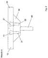
- FIG. 2 shows the detail view A after Fig. 1 , Below the Siebbelagsegmente 10, 20 can be seen the frame 40 of the screening machine.
- the adapter 30 is attached on the frame 40.
- the adapter 30 is fixed to the frame 40 in a form-fitting manner.
- the adapter 30 is made of plastic as an injection molded part.
- permanent magnets 31, 32 are introduced in the matrix of the adapter 30 .
- the two abutting Siebbelagsegmente 10, 20 On the adapter 30 are on the top of the adapter 30, the two abutting Siebbelagsegmente 10, 20.
- This in FIG. 2 left Siebbelagsegment 10 has an iron reinforcement, which forms a ferromagnetic coupling element 11, which forms a magnetic connection with the magnet 31 of the adapter.
- This in FIG. 2 right Siebbelagsegment 20 has an iron reinforcement, which forms a ferromagnetic coupling element 21, which forms a magnetic connection with the magnet 32 of the adapter.
- the reinforcements form reinforcements in the Siebbelagsegmenten 10, 20 and parallel to the support of the frame 40, to which also designed as a strip adapter 30 is attached.
- the Siebbelagsegmente 10, 20 are made of polyurethane, the reinforcements are cast. Due to the course of the reinforcements parallel to the course of the frame 40, the Siebbelagsegmente 10, 20 are flexible, whereby a removal of Siebbelagsegmente 10, 20 of the magnets 31, 32 is facilitated.
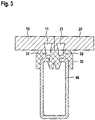
- FIG. 3 shows a second embodiment with a frame 40 formed by a C-profile for receiving the adapter strip 30.
- the adapter strip 30 is formed by a plastic.
- the adapter strip 30 has undercuts, which engage behind the inwardly facing edges of the C-profile 40 and thereby set the adapter bar 30 positively on the C-profile 40.
- permanent magnets 31, 32 are introduced in the matrix of the adapter 30 in the matrix of the adapter 30.
- Siebbelagsegmente 10, 20 to the adapter 30 is the same as previously with respect to the first embodiment according to FIG. 2 explained.
- the two abutting Siebbelagsegmente 10, 20 On the adapter 30 are on the top of the adapter 30, the two abutting Siebbelagsegmente 10, 20.
- This in FIG. 3 left Siebbelagsegment 10 has an iron reinforcement, which forms a ferromagnetic coupling element 11, which forms a magnetic connection with the magnet 31 of the adapter.
- This in FIG. 3 right Siebbelagsegment 20 has an iron reinforcement, which forms a ferromagnetic coupling element 21, which forms a magnetic connection with the magnet 32 of the adapter.
- the reinforcements form reinforcements in the Siebbelagsegmenten 10, 20 and parallel to the C-profile of the frame 40, to which the likewise designed as a bar adapter 30 is attached.
- the Siebbelagsegmente 10, 20 are made of polyurethane, the reinforcements are cast. Due to the course of the reinforcements parallel to the course of the frame 40, the Siebbelagsegmente 10, 20 are flexible, whereby the removal of Siebbelagsegmente 10, 20 of the magnets 31, 32 is facilitated.
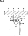
- FIG. 4 shows a third embodiment with a frame formed by an angle profile 40 for receiving the adapter strip 30.
- the adapter strip 30 is formed by a plastic.
- the adapter strip 30 has undercuts, which engage behind the inwardly facing edges of holes in the angle section 40 and thereby define the adapter strip 30 positively on the C-profile 40.
- fastening pins 45 are used, which spread those areas of the adapter 30, which pass through the holes in the angle section 40 after the adapter 30 has been placed on the angle section 40.
- the attachment of the adapter 30 is thus similar to a dowel by spreading the connecting elements and forming a positive connection.
- permanent magnets 31, 32 are introduced into the matrix of the adapter 30.
- the two abutting Siebbelagsegmente 10, 20 On the adapter 30 are on the top of the adapter 30, the two abutting Siebbelagsegmente 10, 20.
- This in FIG. 4 left Siebbelagsegment 10 has an iron reinforcement, which forms a ferromagnetic coupling element 11, which forms a magnetic connection with the magnet 31 of the adapter.
- This in FIG. 4 right Siebbelagsegment 20 has an iron reinforcement, which forms a ferromagnetic coupling element 21, which forms a magnetic connection with the magnet 32 of the adapter.
- the reinforcements form reinforcements in the Siebbelagsegmenten 10, 20 and parallel to the C-profile of the frame 40, to which the likewise designed as a bar adapter 30 is attached.
- the Siebbelagsegmente 10, 20 are made of polyurethane, the reinforcements are cast. Due to the course of the reinforcements parallel to the course of the frame 40, the Siebbelagsegmente 10, 20 are flexible, whereby the removal of Siebbelagsegmente 10, 20 of the magnets 31, 32 is facilitated.
Landscapes
- Engineering & Computer Science (AREA)
- Mechanical Engineering (AREA)
- Combined Means For Separation Of Solids (AREA)
- Belt Conveyors (AREA)
Abstract
Description
- Die Erfindung betrifft ein Befestigungssystem für Siebmaschinen und/oder Setzmaschinen zur Befestigung von auswechselbaren Siebbelagsegmenten und/oder auswechselbaren Verschleißschutzelementen in oder an einer Siebmaschine mit zumindest einem die Siebbelagsegmente aufnehmenden und/oder die Verschleißschutzelemente tragenden Rahmen.
- Derartige Befestigungssysteme sowie Siebmaschinen mit daran befestigbaren und auswechselbaren Siebbelagsegmenten und auswechselbaren Verschleißschutzelementen sind bekannt. Dabei werden die Siebbelagsegmente und Verschleißschutzelemente mittels Schraubverbindungen oder Steckverbindungen an entsprechenden Aufnahmen der Siebmaschine oder Setzmaschinen befestigt.
- Nachteilig bei den bekannten Befestigungssystemen ist es daher, dass eine aufwendige Demontage und Montage notwendig ist, um verschlissene Siebbeiagsegmente und Verschleißschutzelemente zu demontieren und durch neue Siebbelagsegmente und Verschleißschutzelemente zu ersetzen, die häufig mit hohem Kraftaufwand und in äußerst beengten Verhältnissen montiert werden müssen.
- Die Aufgabe der Erfindung ist es, diese Nachteile zu überwinden und ein Siebbelagbefestigungssystem anzugeben, welches eine einfache Demontage und Montage von Siebbelagsegmenten und Verschleißschutzelementen an einer Siebmaschine gestattet.
- Diese Aufgabe wird erfindungsgemäß durch ein Befestigungssystem gemäß Anspruch 1 gelöst. Vorteilhafte Weiterbildungen der Erfindung sind in den Unteransprüchen angegeben.
- Besonders vorteilhaft bei dem Befestigungssystem für Siebmaschinen zur Befestigung von auswechselbaren Siebbelagsegmenten und/oder auswechselbaren Verschleißschutzelementen in oder an einer Siebmaschine mit zumindest einem die Siebbelagsegmente aufnehmenden und/oder die Verschleißschutzelemente tragenden Rahmen, ist es, dass zur Befestigung eines Siebbelagsegmentes und/oder eines Verschleißschutzelementes zumindest ein Adapter an dem Rahmen befestigt ist, wobei der Adapter zumindest einen Magneten aufweist, wobei der Magnet mit dem Rahmen und/oder mit zumindest einem in oder an dem Siebbelagsegment und/oder Verschleißschutzelement schwingungsfest angeordneten ferromagnetischen Kopplungselement zusammenwirkt und hierdurch eine magnetische Verbindung zwischen dem Adapter und dem Rahmen und/oder zwischen dem Adapter und dem Siebbelagsegment und/oder Verschleißschutzelement herstellt.
- Im erfindungsgemäßen Sinn werden die Begriffe Siebmaschine und Setzmaschine synonym verwendet.
- Erfindungsgemäß ist somit vorgesehen, die einem Verschleiß unterliegenden Siebbelagsegmente und Verschleißschutzelemente durch eine magnetische Kopplung an Adaptern zu befestigen, wobei jeder Adapter jeweils zumindest einen Magneten aufweist, der eine magnetische Verbindung mit einem dem Siebbelagsegment und/oder Verschleißschutzelement zugeordneten ferromagnetischen Kopplungselement bildet. Der den Magneten aufweisende Adapter verbleibt bei jedem Austausch eines verschlissenen Siebbelagsegmentes oder Verschleißschutzelementes an dem Rahmen der Siebmaschine. Zum Austausch eines Verschleißteiles muss lediglich die magnetische Verbindung gelöst und ein neues Siebbelagsegment und/oder Verschleißschutzelement aufgelegt werden. Die Siebbelagsegmente und/oder Verschleißschutzelemente werden somit magnetisch an der Siebmaschine befestigt.
- Alternativ oder kumulativ kann der Adapter selbst magnetisch an dem Rahmen der Siebmaschine festgelegt sein. Die auswechselbaren Siebbelagsegmente und/der die auswechselbaren Versähleißschutzelemente können magnetisch und/der formschlüssig und/oder kraftschlüssig mittelbar oder unmittelbar an dem Adapter befestigt sein. Durch eine magnetische Befestigung des Adapters an dem Rahmen der Siebmaschine wird eine leicht montierbare und demontierbare Befestigung des Adapters realisiert.
- Die magnetische und/der formschlüssige und/oder kraftschlüssige Befestigung der Siebbelagsegmente und/oder Verschleißschutzelemente an dem Adapter kann mittelbar oder unmittelbar erfolgen.
- Der Siebboden kann auch durch ein einzelnes, einstückiges Siebbelagsegment gebildet sein. Die Erfindung ist somit nicht auf eine Anwendung mit einem aus mehreren Siebbelagsegmenten gebildeten Siebboden beschränkt, wenngleich dies eine bevorzugte Ausführung darstellt.
- Dadurch ist es gewährleistet, dass die als Verschleißteile geltenden Siebbelagsegmente und/oder Verschleißschutzelemente mittels der magnetischen Zusammenwirkung zwischen dem zumindest einen Magneten des an dem Rahmen der Siebmaschine befestigten Adapters und dem zumindest einen in oder an dem Siebbelagsegment und/oder Verschleißschutzelement angeordneten ferromagnetischen Kopplungselement befestigt werden können. Somit können die Siebbelagsegmente und/oder Verschleißschutzelemente auf eine einfache Art und Weise demontiert und montiert werden. Ferner kann eine derartige Adapterleiste ohne großen Aufwand an bereits bestehenden Siebmaschinen nachgerüstet werden, sodass an der Siebmaschine selbst keine Änderungen vorgenommen werden müssen.
- Bevorzugt ist der Adapter an einem Bauteil der Siebmaschine aus nicht ferromagnetischem Material befestigt. Insbesondere kann der Adapter kraftschlüssig und/oder stoffschlüssig und/oder formschlüssig befestigt sein. Beispielsweise handelt es sich bei Edelstahl um ein nicht ferromagnetisches Material. Ferner kann der Adapter somit als Befestigungs- und Verbindungselement dienen, indem er selbst an nichtmagnetischen Flächen und Bauteilen beispielsweise aus Edelstahl befestigt wird. Durch eine solche Anordnung des Adapters mit zumindest einem Magneten ist auch eine magnetische Befestigung von Siebbelagsegmenten und/oder Verschleißschutzelementen an Bauteilen aus einem nicht ferromagnetischen Material möglich.
- Alternativ zu einer Befestigung des Adapters an einem Bauteil der Siebmaschine aus nicht ferromagnetischem Material kann der Adapter an einem ferromagnetischen Bauteil der Siebmaschine befestigt sein. Insbesondere kann der Adapter magnetisch und/oder kraftschlüssig und/oder stoffschlüssig und/oder formschlüssig befestigt sein. Insbesondere kann der Adapter beidseitig wirkende Magnete aufweisen, mittels derer der Adapter selbst magnetisch an einem ferromagnetischen Bauteil der Siebmaschine befestigt wird und die gleichzeitig dazu dienen, mit zumindest einem in oder an dem Siebbelagsegment und/oder Verschleißschutzelement schwingungsfest angeordneten ferromagnetischen Kopplungselement zusammenzuwirken und hierdurch eine magnetische Verbindung zwischen dem Adapter und dem Siebbelagsegment und/oder Verschleißschutzelement herzustellen. In diesem Fall der Anordnung von beidseitig wirkenden Magneten dienen die Magnete somit sowohl der magnetischen Befestigung des Adapters an der Siebmaschine als auch der magnetischen Befestigung des Siebbelages oder des Verschleißschutzelementes an dem Adapter.
- Insbesondere können derartige Adapter auch an Seitenteilen von Siebmaschinen angebracht sein und der Befestigung seitlicher Verschleißschutzelemente dienen. Bei diesen Seitenteilen kann es sich beispielsweise um senkrechte Begrenzungswände oberhalb des Siebbodens handeln. Ferner kann es sich um Adapter für Wellenschutzrohre handeln, die sich um das Rohr legen, dort magnetisch haften und ihrerseits ein sich um das Rohr legende Verschleißschutzelement magnetisch halten.
- Der Adapter kann insbesondere als längliche Adapterleiste ausgebildet sein. Der Rahmen der Siebmaschine, welcher die Adapter oder Adapterleisten aufnimmt, kann durch X-Profile und/oder C- Profile und/oder U- Profile und/oder T-Profile und/oder KR-Profile und/oder Winkelprofile gebildet sein. Der Adapter kann durch ein Kunststoffbauteil gebildet sein, insbesondere als Spritzgussteil mit einem oder mehreren eingegossenen Magneten. Der Adapter kann Bohrungen insbesondere zur Aufnahme von Befestigungsdübeln zur Befestigung des Adapters an sogenannten KR-Profilen und/oder Winkelprofilen aufweisen.
- Die Befestigung des Adapters an dem Rahmen der Siebmaschine kann Insbesondere kraftschlüssig und/oder stoffschlüssig und/oder formschlüssig erfolgen. Mit dem Begriff des Rahmens der Siebmaschine ist dabei jedes Bauteil der Siebmaschine umfasst, an welchem ein auswechselbares Siebbelagsegment und/oder ein auswechselbares Verschleißschutzelement insbesondere mittelbar befestigt wird.
- Ein besonderer Vorteil der Erfindung ist es somit, dass das Befestigungssystem für Siebmaschinen zur Befestigung von auswechselbaren Siebbelagsegmenten und/oder auswechselbaren Verschleißschutzelementen durch die Anordnung von Adaptern bei vorhandenen Siebmaschinen nachgerüstet werden kann, da die Adapter an den ursprünglich für die Siebbelagsegmente und/oder Verschleißschutzelemente vorgesehenen Aufnahmen und Befestigungsorten befestigt werden können. Die Magnete werden dabei in oder an den an der Siebmaschine verbleibenden Adaptern angeordnet.
- Vorzugsweise weist jeder Adapter eine Mehrzahl von insbesondere äquidistant angeordneten Magneten auf. Durch die Anordnung mehrerer Magneten bei jedem Adapter, insbesondere bei Adaptern in Form von länglichen Adapterleisten, kann die magnetische Haltekraft gesteigert und gleichmäßig beispielsweise entlang der Kanten der zu befestigenden Siebbelagsegmente und/oder Verschleißschutzelemente ausgeübt werden.
- In einer bevorzugten Ausführungsform sind ein oder mehrere ferromagnetische Kopplungselemente in jedem Siebbelagsegment und/oder jedem Verschleißschutzelement eingegossen und/oder das ferromagnetische Kopplungselement ist durch das Siebbelagsegment und/oder das Verschleißschutzelement selbst gebildet. Insbesondere können die Siebbelagsegmente und/oder die Verschleißschutzelemente durch Polyurethan gebildet sein, in denen ferromagnetische Kopplungselemente eingegossen sind. Die ferromagnetischen Kopplungselemente können gleichzeitig mechanische Verstärkungen in den Siebbelagsegmenten und/oder Verschleißschutzelementen bilden. Das bedeutet, dass die in den Siebbelagsegmenten und/oder Verschleißschutzelementen eingegossenen ferromagnetischen Kopplungselemente gleichzeitig Armierungen der Siebbelagsegmente und/oder Verschleißschutzelemente bilden. Umgekehrt können die zur Erhöhung der Tragfestigkeit ohnehin in den Siebbelagsegmenten und/oder Verschleißschutzelementen vorgesehenen Metallarmierungen gleichzeitig als ferromagnetische Kopplungselemente zur Herstellung der magnetischen Verbindung mit den Magneten der Adapter oder Adapterleisten dienen.
- Vorzugsweise sind ein oder mehrere ferromagnetische Kopplungselemente durch Montageleisten und/oder Montagerahmen gebildet, die magnetisch an dem Adapter festgelegt sind, wobei Siebbelagsegmente und/oder Verschleißschutzelemente kraftschlüssig und/oder formschlüssig schwingungsfest an den Montageleisten und/oder Montagerahmen festgelegt sind.
- Es können somit eine oder mehrere Montageleisten und/oder Montagerahmen aus ferromagnetischem Material zur Herstellung der magnetischen Verbindung mit den Adaptern angeordnet sein, wobei die Siebbelagsegmente und/oder Verschleißschutzelemente kraftschlüssig und/oder formschlüssig schwingungsfest und insbesondere auswechselbar an den Montageleisten und/oder Montagerahmen befestigt sind.
- Ferner kann das Siebbelagsegment insbesondere durch ein Lochblech aus ferromagnetischem Material gebildet sein. Die Siebbelagsegmente können insbesondere durch ein ferromagnetisches Lochblech mit einer darauf aufgespritzten Polyurethanschicht gebildet sein. Bei einem beschichteten Lochblech kann die auf das Lochblech aufgebrachte Beschichtung eine andere, insbesondere kleinere Maschenweite aufweisen, als das als Träger dienende Lochblech.
- Das ferromagnetische Kopplungselement kann durch Eisen oder eine Eisenlegierung gebildet sein. Hierdurch wird eine günstige Lösung mit einer besonders guten magnetischen Haltekraft geschaffen. Wie zuvor erläutert kann das ferromagnetische Kopplungselement insbesondere durch einen eingegossenen Eisenkern in dem Siebbelagsegment und/oder Verschleißschutzelement gebildet sein, insbesondere kann das ferromagnetische Kopplungselement in Form einer Strebe oder in Form eines Rahmens in dem Material des Siebbelagsegmentes und/oder des Verschleißschutzelementes eingegossen sein und ein Verstärkungselement zur Aussteifung des Siebbelagsegmentes und/oder des Verschleißschutzelementes bilden. Insbesondere kann das Siebbelagsegment und/oder das Verschleißschutzelement mittels des ferromagnetischen Kopplungselementes armiert sein.
- Den Verschleißteilen sind somit lediglich die gegenüber Magneten preiswerteren ferromagnetische Kopplungselemente beispielsweise in Form von Eisenkernen zugeordnet, die auf leichte Weise wiederverwendet werden können. Die Siebbelagsegmente und/oder Verschleißschutzelemente selbst können aus nicht ferromagnetischem Material, insbesondere Polyurethan gebildet sein.
- In einer bevorzugten Ausführungsform ist das ferromagnetische Kopplungselement eines Siebbelagsegmentes durch ein Lochblech aus ferromagnetischem Material gebildet, welches einen Träger für Siebmedien, insbesondere Gewebe, bildet. In diesem Fall wird ein Lochblech aus ferromagnetischem Material durch die magnetische Kopplung an den Adaptern befestigt und dient als Träger für an dem Lochblech befestigte Siebmedien, wie beispielsweise Gewebe und dergleichen. Beim Austausch verschlissener Siebmedien wird das ferromagnetische Lochblech als Träger weiter verwendet und nur das darauf befestigte Siebmedium wie ein Gewebe ersetzt.
- Bevorzugt ist das ferromagnetische Kopplungselement parallel zum Verlauf eines länglichen Adapters durchgehend oder abschnittweise ausgebildet. Insbesondere kann das ferromagnetische Kopplungselement dem Kantenverlauf eines Siebbelagsegmentes und/oder eines Verschleißschutzelementes folgen, um eine gute und sichere Befestigung des jeweiligen Siebbelagsegmentes und/oder Verschleißschutzelementes gerade im Kantenbereich zu gewährleisten. Der Verlauf des länglichen Adapters folgt dabei vorzugsweise ebenfalls dem Kantenverlauf eines Siebbelagsegmentes und/oder eines Verschleißschutzelementes, um die magnetische Befestigung des jeweiligen Siebbelagsegmentes und/oder Verschleißschutzelementes gerade im Kantenbereich zu gewährleisten.
- Das ferromagnetische Kopplungselement kann einstückig oder mehrstückig ausgebildet sein, insbesondere als eingegossener Kern, welcher in die Matrix eines Siebbelagsegmentes und/oder Verschleißschutzelementes eingebettet ist. Vorteilhaft ist dabei, dass die Magnete nicht exakt positioniert werden müssen, um eine gute Befestigung zu gewährleisten. Es bedarf somit keiner exakten und abgestimmten Paarung jeweils eines Magneten des Adapters mit einem korrespondierenden ferromagnetischen Kopplungselement, wenn einerseits mehrere Magnete an einem beispielsweise leistenförmigen Adapter angeordnet sind und gleichzeitig mehrere ferromagnetische Kopplungselemente abschnittsweise in der Matrix eines Siebbelagsegmentes und/oder Verschleißschutzelementes eingebettet sind und/oder ein durchgehender Eisenkern beispielsweise in Form eines Rahmens oder einer Verstärkung angeordnet ist. Dieselben Vorteile werden durch eine Armierung aus ferromagnetischem Material des Siebbelagsegmentes und/oder Verschleißschutzelementes erzielt. In diesen Fällen ist eine gute und standfeste Befestigung an den Magneten gewährleistet. Die Matrix eines Siebbelagsegmentes und/oder Verschleißschutzelementes selbst kann dabei durch ein flexibles Material wie beispielsweise Polyurethan gebildet sein.
- In einer bevorzugten Ausführungsform bilden mehrere Siebbelagsegmente einen Siebboden. Insbesondere können dabei benachbarte Siebbeiagsegmente jeweils einen Formschluss bilden, insbesondere eine Nut-Feder-Verbindung aufweisen. Durch derartige formschlüssige Verbindungen der Siebbelagsegmente untereinander wird ein Siebbelagsegment bei einer Beaufschlagung mit Siebgut zusätzlich zur magnetischen Fixierung auch durch die benachbarten Siebbelagsegmente gesichert und fixiert.
- Vorzugsweise bilden mehrere Siebbelagsegmente einen Siebboden, wobei die in Transportrichtung des Siebgutes letzten Siebbelagsegmente sich in Transportrichtung endseitig gegen Queranschlagelemente abstützen, insbesondere gegen eine durchgehende Queranschlagleiste abstützen. Insbesondere können die Siebbelagsegmente mit der senkrecht zur Transportrichtung verlaufenden Queranschlagleiste einen Formschluss, insbesondere eine Nut-Feder-Verbindung bilden.
- Siebböden werden üblicherweise unter einem Winkel gegen die Horizontale aufgestellt wobei das aufzubereitende Siebgut an dem geodätisch höher gelegenen Ende des Siebbodens auf den Siebboden aufgebracht und über das geodätisch tiefer gelegene Ende des Siebbodens abgeführt wird. Zur Aufnahme der Schubkräfte in Transportrichtung ist es daher vorteilhaft, wenn sich die in Transportrichtung des Siebgutes letzten Siebbelagsegmente endseitig gegen Queranschlagelemente abstützen. Die Anordnung dieser Queranschlagelemente ist somit quer zur Transportrichtung des Siebgutes.
- Diese Queranschlagelemente, insbesondere eine die Schubkräfte aufnehmende Queranschlagleiste, können am Rahmen befestigt oder durch den Rahmen, welcher die Siebsegmente aufnimmt, selbst gebildet sein.
- Insbesondere können die Queranschlagelemente ferner durch an entsprechender Stelle des Rahmens angeordnete Adapter gebildet sein.
- Vorzugsweise bilden mehrere Siebbelagsegmente einen Siebboden, wobei die Siebbelagsegmente sich seitlich in Richtung senkrecht zur Transportrichtung des Siebgutes gegen parallel zur Transportrichtung verlaufende Längsanschlagelemente, insbesondere Längsanschlagleisten, abstützen, insbesondere dass die Siebbelagsegmente mit den parallel zur Transportrichtung verlaufenden Längsanschlagleisten einen Formschluss, insbesondere eine Nut-Feder-Verbindung bilden.
- Derartige in Transportrichtung des Siebgutes seitlich neben den Siebbelagsegmenten angeordnete Längsanschlagleisten dienen der Aufnahme der Querkräfte und sichern die Siebbelagsegmente in seitlich in Richtung senkrecht zur Transportrichtung. Die Längsanschlagleisten erstrecken sich an den Seiten des Siebbodens parallel zur Transportrichtung des Siebgutes. Die Längsanschlagleisten können am Rahmen befestigt oder durch den Rahmen, welcher die Siebsegmente aufnimmt, selbst gebildet sein. Insbesondere können die Längsanschlagleisten ferner durch an entsprechender Stelle des Rahmens angeordnete Adapter gebildet sein.
- In einer bevorzugten Ausführungsform weisen der/die Magnete und/oder der/die ferromagnetischen Kopplungselemente zumindest eine Hinterschneidung auf. Derartige Hinterschneidungen bilden insbesondere eine Angusskante für die Fertigung der Adapter bzw. der Siebbelagsegmente und/oder der Verschleißschutzelemente aus Kunststoff, insbesondere Polyurethan, und erleichtern den Fertigungsprozess. Ferner ergibt sich hierdurch ein besserer Halt am Adapter bzw. am Siebbelagsegment und/oder am Verschleißschutzelement.
- Bevorzugt bilden die Siebbelagsegmente und/oder die Verschleißschutzelemente und die jeweiligen Adapter zur Befestigung der Siebbelagsegmente und/oder Verschleißschutzelemente einen Formschluss, insbesondere eine Nut-Feder-Verbindung. Durch einen derartigen Formschluss zusätzlich zur magnetischen Befestigung der Siebbelagsegmente und/oder der Verschleißschutzelemente an dem jeweiligen Adapter wird die Tragfähigkeit der Verbindung der Siebbelagsegmente und/oder der Verschleißschutzelemente an den Adaptern weiter erhöht.
- Derartige formschlüssige Verbindungen zwischen den Siebbelagsegmenten und dem jeweiligen Adapter können an der Längsseite der Siebbelagsegmente vorgesehen sein, d.h. an den Seiten der Siebbelagsegmente, die in der Einbausituation in Transportrichtung des Siebgutes verlaufen. Alternativ oder kumulativ können derartige formschlüssige Verbindungen zwischen den Siebbelagsegmenten und dem jeweiligen Adapter an den Querseiten der Siebbelagsegmente vorgesehen sein, d.h. an den Seiten der Siebbelagsegmente, die in der Einbausituation senkrecht zur Transportrichtung des Siebgutes verlaufen. Derartige formschlüssige Verbindungen zwischen den Siebbelagsegmenten und dem jeweiligen Adapter dienen der zusätzlichen Fixierung der Siebbelagsegmente kumulativ zur magnetischen Befestigung der Siebbelagsegmente an den Adaptern und verhindern ein Verrutschen der Siebbelagsegmente auf den Adaptern in Transportrichtung und/oder senkrecht zur Transportrichtung des Siebgutes.
- Vorzugsweise sind die Adapter durch Adapterleisten mit einer symmetrischen Anordnung mehrerer Magnete gebildet und/oder die Siebbelagsegmente weisen eine rotationssymmetrische Anordnung mehrerer ferromagnetischer Kopplungselemente und eine quadratische Grundform auf.
- Vorzugsweise weisen die Adapter selbst einen symmetrischen Aufbau auf. Bei Verwendung symmetrisch aufgebauter Adapter können diese in verschiedenen Orientierungen eingebaut werden, wodurch die Montage für den Monteur erleichtert wird.
- Vorzugsweise weisen die Siebbelagsegmente und/oder Verschleißschutzelemente einen symmetrischen, insbesondere rotationssymmetrischen Aufbau auf. Bei Verwendung symmetrisch aufgebauter Siebbelagsegmente und/oder Verschleißschutzelemente können diese in verschiedenen Orientierungen eingebaut werden, wodurch die Montage für den Monteur erleichtert wird.
- Besonders bevorzugt werden Adapterleisten mit einer symmetrischen Anordnung mehrerer Magnete und Siebbelagsegmente mit einer quadratischen Grundform und einer rotationssymmetrischen Anordnung mehrerer ferromagnetischer Kopplungselemente miteinander kombiniert. Durch eine derartige Gestaltung der Adapter als Adapterleisten zur Anbringung am Rahmen der Siebmaschine einerseits und einer quadratischen Ausführung der Siebbelagsegmente und einer entsprechenden symmetrischen Anordnung der ferromagnetischen Kopplungselemente andererseits können die Siebbelagsegmente in beliebiger Anordnung an den Adapterleisten befestigt werden, ohne dass es zur Montage einer bestimmten Ausrichtung bedarf. Dies bedeutet, dass eine Verwendung und Anbringung in verschiedenen Richtungen möglich ist. Hierdurch wird das Auswechseln und Montieren der Siebbelagsegmente erleichtert.
- Vorzugsweise weist der Adapter beidseitig wirkende Magnete auf und/oder der Adapter ist beidseitig mit Magneten ausgestattet, sodass eine magnetische Befestigung des Adapters an dem Rahmen und eine magnetische Befestigung eines Siebbelagsegmentes und/oder eines Verschleißschutzelementes an dem Adapter erfolgen kann. Durch die Weiterbildung des Adapters dahingehend, dass der Adapter selbst ebenfalls magnetisch an dem Rahmen der Siebmaschine befestigt wird und ferner die Siebbelagsegmente und/oder die Verschleißschutzelemente magnetisch an dem Adapter befestigt werden, ist eine Nachrüstung vorhandener Siebmaschinen auf eine besonders vorteilhafte und einfache Weise möglich. Es kann somit auch der Adapter selbst magnetisch befestigt sein.
- Besonders vorteilhaft ist eine Siebmaschine mit einem Tragrahmen zur Aufnahme einer Mehrzahl von Siebbelagsegmenten zur Bildung eines Siebbodens, bei der der Tragrahmen ein erfindungsgemäßes Siebbelagbefestigungssystem aufweist.
- Drei Ausführungsbeispiele der Erfindung sind in den Figuren dargestellt und werden nachfolgend näher erläutert. Es zeigen:
- Fig. 1
- Eine schematische perspektivische Ansicht eines aus mehreren Siebbelagsegmenten gebildeten Siebbodens;
- Fig. 2
- die Detailansicht A nach
Fig. 1 ; - Fig. 3
- ein zweites Ausführungsbeispiel mit einem durch ein C-Profil gebildeten Rahmen zur Aufnahme der Adapterleiste;
- Fig. 4
- ein drittes Ausführungsbeispiel mit einem durch ein Winkelprofil gebildeten Rahmen zur Aufnahme der Adapterleiste.
- In den Figuren sind identische Bauteile mit identischen Bezugszeichen versehen.
-
Figur 1 zeigt eine schematische perspektivische Ansicht eines aus mehreren Siebbelagsegmenten 10, 20 gebildeten Siebbodens einer Siebmaschine. Die Siebbelagsegmente 10, 20 unterliegen einem Verschleiß und sind auswechselbar an dem Rahmen 40 der Siebmaschine befestigt. Die Transportrichtung des Siebgutes ist durch den Pfeil 5 gekennzeichnet. Das bedeutet, dass das aufzubereitende Siebgut in dem in der Darstellung nachFigur 1 am oberen Bildrand gelegene hintere Ende des Siebbodens aufgebracht und über das in der Darstellung nachFigur 1 am unteren Bildrand gelegene vordere Ende des Siebbodens abtransportiert wird. - Seitlich stützen sich die Siebbelagsegmente 10, 20 gegen die parallel zur Transportrichtung 5 verlaufenden Längsanschlagleisten 41, 42 ab, um etwaige auf die Siebbelagsegmenten 10, 20 wirkende Querkräfte auf den Rahmen 40 abzuleiten.
- Zur Aufnahme der Schubkräfte in Transportrichtung des Siebgutes stützen sich die Transportrichtung des Siebgutes letzten Siebbelagsegmente 10, 20 endseitig gegen die durchgehende Queranschlagleiste 45 des Rahmens 40 ab. Hierdurch werden die auf die Siebbelagsegmente 10, 20 wirkenden Schubkräfte in Transportrichtung des Siebgutes durch den Rahmen 40 der Siebmaschine aufgenommen.
-
Figur 2 . zeigt die Detailansicht A nachFig. 1 . Unterhalb der Siebbelagsegmente 10, 20 ist erkennbar der Rahmen 40 der Siebmaschine. An dem Rahmen 40 ist der Adapter 30 befestigt. Der Adapter 30 ist an dem Rahmen 40 formschlüssig befestigt. Der Adapter 30 ist aus Kunststoff als Spritzgussteil ausgeführt. In die Matrix des Adapters 30 sind Dauermagnete 31, 32 eingebracht. - Auf dem Adapter 30 liegen auf der Oberseite des Adapters 30 die beiden aneinander stoßenden Siebbelagsegmente 10, 20 auf. Das in
Figur 2 linke Siebbelagsegment 10 weist eine Eisenarmierung auf, die ein ferromagnetisches Kopplungselement 11 bildet, welches eine magnetische Verbindung mit dem Magneten 31 des Adapters bildet. Das inFigur 2 rechte Siebbelagsegment 20 weist eine Eisenarmierung auf, die ein ferromagnetisches Kopplungselement 21 bildet, welches eine magnetische Verbindung mit dem Magneten 32 des Adapters bildet. Die Armierungen bilden Verstärkungen in den Siebbelagsegmenten 10, 20 und verlaufen parallel zum Träger des Rahmens 40, an welchem der ebenfalls als Leiste ausgebildete Adapter 30 befestigt ist. Die Siebbelagsegmente 10, 20 bestehen aus Polyurethan, wobei die Armierungen eingegossen sind. Durch den Verlauf der Armierungen parallel zum Verlauf des Rahmens 40 sind die Siebbelagsegmente 10, 20 biegsam, wodurch ein Abnehmen der Siebbelagsegmente 10, 20 von den Magneten 31, 32 erleichtert wird. -
Figur 3 zeigt ein zweites Ausführungsbeispiel mit einem durch ein C-Profil gebildeten Rahmen 40 zur Aufnahme der Adapterleiste 30. Die Adapterleiste 30 ist durch einen Kunststoff gebildet. Die Adapterleiste 30 weist Hinterschneidungen auf, welche die nach innen weisenden Kanten des C-Profils 40 hintergreifen und hierdurch die Adapterleiste 30 formschlüssig an dem C-Profil 40 festlegen. In die Matrix des Adapters 30 sind Dauermagnete 31, 32 eingebracht. - Die Befestigung der Siebbelagsegmente 10, 20 an dem Adapter 30 erfolgt genauso wie zuvor in Bezug auf das erste Ausführungsbeispiel gemäß
Figur 2 erläutert. Auf dem Adapter 30 liegen auf der Oberseite des Adapters 30 die beiden aneinander stoßenden Siebbelagsegmente 10, 20 auf. Das inFigur 3 linke Siebbelagsegment 10 weist eine Eisenarmierung auf, die ein ferromagnetisches Kopplungselement 11 bildet, welches eine magnetische Verbindung mit dem Magneten 31 des Adapters bildet. Das inFigur 3 rechte Siebbelagsegment 20 weist eine Eisenarmierung auf, die ein ferromagnetisches Kopplungselement 21 bildet, welches eine magnetische Verbindung mit dem Magneten 32 des Adapters bildet. Die Armierungen bilden Verstärkungen in den Siebbelagsegmenten 10, 20 und verlaufen parallel zum C-Profil des Rahmens 40, an welchem der ebenfalls als Leiste ausgebildete Adapter 30 befestigt ist. Die Siebbelagsegmente 10, 20 bestehen aus Polyurethan, wobei die Armierungen eingegossen sind. Durch den Verlauf der Armierungen parallel zum Verlauf des Rahmens 40 sind die Siebbelagsegmente 10, 20 biegsam, wodurch das Abnehmen der Siebbelagsegmente 10, 20 von den Magneten 31, 32 erleichtert wird. -
Figur 4 zeigt ein drittes Ausführungsbeispiel mit einem durch ein Winkelprofil gebildeten Rahmen 40 zur Aufnahme der Adapterleiste 30. Die Adapterleiste 30 ist durch einen Kunststoff gebildet. Die Adapterleiste 30 weist Hinterschneidungen auf, welche die nach innen weisenden Kanten von Bohrungen in dem Winkelprofil 40 hintergreifen und hierdurch die Adapterleiste 30 formschlüssig an dem C-Profil 40 festlegen. Zur Sicherung des Adapters 30 an dem Winkelprofil sind Befestigungsstifte 45 eingesetzt, welche jene Bereiche des Adapters 30 aufspreizen, die die Bohrungen in dem Winkelprofil 40 durchgreifen, nachdem der Adapter 30 auf das Winkelprofil 40 aufgesetzt wurde. Die Befestigung des Adapters 30 erfolgt somit ähnlich wie bei einem Dübel durch Aufspreizen der Verbindungselemente und Bildung eines Formschlusses. In die Matrix des Adapters 30 sind wiederum Dauermagnete 31, 32 eingebracht. - Die Befestigung der Siebbelagsegmente 10, 20 an dem Adapter 30 erfolgt ebenfalls wie zuvor in Bezug auf das erste Ausführungsbeispiel gemäß
Figur 2 und das zweite Ausführungsbeispiel gemäßFigur 3 erläutert. - Auf dem Adapter 30 liegen auf der Oberseite des Adapters 30 die beiden aneinander stoßenden Siebbelagsegmente 10, 20 auf. Das in
Figur 4 linke Siebbelagsegment 10 weist eine Eisenarmierung auf, die ein ferromagnetisches Kopplungselement 11 bildet, welches eine magnetische Verbindung mit dem Magneten 31 des Adapters bildet. Das inFigur 4 rechte Siebbelagsegment 20 weist eine Eisenarmierung auf, die ein ferromagnetisches Kopplungselement 21 bildet, welches eine magnetische Verbindung mit dem Magneten 32 des Adapters bildet. Die Armierungen bilden Verstärkungen in den Siebbelagsegmenten 10, 20 und verlaufen parallel zum C-Profil des Rahmens 40, an welchem der ebenfalls als Leiste ausgebildete Adapter 30 befestigt ist. Die Siebbelagsegmente 10, 20 bestehen aus Polyurethan, wobei die Armierungen eingegossen sind. Durch den Verlauf der Armierungen parallel zum Verlauf des Rahmens 40 sind die Siebbelagsegmente 10, 20 biegsam, wodurch das Abnehmen der Siebbelagsegmente 10, 20 von den Magneten 31, 32 erleichtert wird.
Claims (16)
- Befestigungssystem für Siebmaschinen und/oder Setzmaschinen zur Befestigung von auswechselbaren Siebbelagsegmenten (10, 20) und/oder auswechselbaren Verschleißschutzelementen in oder an einer Siebmaschine mit zumindest einem die Siebbelagsegmente (10, 20) aufnehmenden und/oder die Verschleißschutzelemente tragenden Rahmen (40), dadurch gekennzeichnet, dass zur Befestigung eines Siebbelagsegmentes (10, 20) und/oder eines Verschleißschutzelementes zumindest ein Adapter (30) an dem Rahmen (40) befestigt ist, wobei der Adapter (30) zumindest einen Magneten (31, 32) aufweist, wobei der Magnet mit dem Rahmen (40) und/oder mit zumindest einem in oder an dem Siebbelagsegment (10, 20) und/oder Verschleißschutzelement schwingungsfest angeordneten ferromagnetischen Kopplungselement (11, 21) zusammenwirkt und hierdurch eine magnetische Verbindung zwischen dem Adapter (30) und dem Rahmen (40) und/oder zwischen dem Adapter (30) und dem Siebbelagsegment (10, 20) und/oder Verschleißschutzelement herstellt.
- Befestigungssystem nach Anspruch 1, dadurch gekennzeichnet, dass der Adapter (30) an einem Bauteil der Siebmaschine aus nicht ferromagnetischem Material befestigt ist, insbesondere dass der Adapter (30) kraftschlüssig und/oder stoffschlüssig und/oder formschlüssig befestigt ist.
- Befestigungssystem nach Anspruch 1, dadurch gekennzeichnet, dass der Adapter (30) an einem Bauteil der Siebmaschine aus ferromagnetischem Material befestigt ist, insbesondere dass der Adapter (30) magnetisch und/oder kraftschlüssig und/oder stoffschlüssig und/oder formschlüssig befestigt ist.
- Befestigungssystem nach Anspruch 1 oder 2, dadurch gekennzeichnet, dass jeder Adapter (30) eine Mehrzahl von insbesondere äquidistant angeordneten Magneten (31, 32) aufweist.
- Befestigungssystem nach einem der vorherigen Ansprüche, dadurch gekennzeichnet, dass ein oder mehrere ferromagnetische Kopplungselemente (11, 21) in jedem Siebbelagsegment (10, 20) und/oder jedem Verschleißschutzelement eingegossen ist und/oder dass das ferromagnetische Kopplungselemente (11, 21) durch das Siebbelagsegment (10, 20) und/oder das Verschleißschutzelement selbst gebildet ist.
- Befestigungssystem nach einem der vorherigen Ansprüche, dadurch gekennzeichnet, dass ein oder mehrere ferromagnetische Kopplungselemente (11, 21) durch Montageleisten und/oder Montagerahmen gebildet sind, die magnetisch an dem Adapter (30) festgelegt sind, wobei Siebbelagsegmente (10, 20) und/oder Verschleißschutzelemente kraftschlüssig und/oder formschlüssig schwingungsfest an den Montageleisten und/oder Montagerahmen festgelegt sind.
- Befestigungssystem nach einem der vorherigen Ansprüche, dadurch gekennzeichnet, dass das ferromagnetische Kopplungselement (11, 21) eines Siebbelagsegmentes (10, 20) durch ein Lochblech aus ferromagnetischem Material gebildet ist, welches einen Träger für Siebmedien, insbesondere Gewebe, bildet.
- Befestigungssystem nach einem der vorherigen Ansprüche, dadurch gekennzeichnet, dass das ferromagnetische Kopplungselement (11, 21) parallel zum Verlauf eines länglichen Adapters (30) durchgehend oder abschnittweise ausgebildet ist.
- Befestigungssystem nach einem der vorherigen Ansprüche, dadurch gekennzeichnet, dass mehrere Siebbelagsegmente (10, 20) einen Siebboden bilden, insbesondere wobei benachbarte Siebbelagsegmente (10, 20) jeweils einen Formschluss bilden, insbesondere eine Nut-Feder-Verbindung aufweisen.
- Befestigungssystem nach einem der vorherigen Ansprüche, dadurch gekennzeichnet, dass mehrere Siebbelagsegmente (10, 20) einen Siebboden bilden, wobei die in Transportrichtung des Siebgutes letzten Siebbelagsegmente (10, 20) sich in Transportrichtung endseitig gegen Queranschlagelemente abstützen, Insbesondere gegen eine durchgehende Queranschlagleiste (45) abstützen, insbesondere dass die Siebbelagsegmente (10, 20) mit der senkrecht zur Transportrichtung verlaufenden Queranschlagleiste (45) einen Formschluss, insbesondere eine Nut-Feder-Verbindung bilden.
- Befestigungssystem nach einem der vorherigen Ansprüche, dadurch gekennzeichnet, dass mehrere Siebbelagsegmente (10, 20) einen Siebboden bilden, wobei die Siebbelagsegmente (10, 20) sich seitlich in Richtung senkrecht zur Transportrichtung des Siebgutes gegen parallel zur Transportrichtung verlaufende Längsanschlagelemente (41,42), insbesondere Längsanschlagleisten abstützen, insbesondere dass die Siebbelagsegmente (10, 20) mit den parallel zur Transportrichtung verlaufende Längsanschlagleisten einen Formschluss, insbesondere eine Nut-Feder-Verbindung bilden.
- Befestigungssystem nach einem der vorherigen Ansprüche, dadurch gekennzeichnet, dass der/die Magnete (31, 32) und/oder der/die ferromagnetischen Kopplungselemente (11, 21) zumindest eine Hinterschneidung aufweisen.
- Befestigungssystem nach einem der vorherigen Ansprüche, dadurch gekennzeichnet, dass die Siebbelagsegmente und die jeweiligen Adapter (30) zur Befestigung der Siebbelagsegmente (10, 20) einen Formschluss bilden, insbesondere eine Nut-Feder-Verbindung bilden.
- Befestigungssystem nach einem der vorherigen Ansprüche, dadurch gekennzeichnet, dass die Adapter (30) durch Adapterleisten mit einer symmetrischen Anordnung mehrerer Magnete (31, 32) gebildet sind und/oder dass die Siebbelagsegmente (10, 20) eine rotationssymmetrische Anordnung mehrerer ferromagnetischer Kopplungselemente (11, 21) und eine quadratische Grundform aufweisen.
- Befestigungssystem nach einem der vorherigen Ansprüche, dadurch gekennzeichnet, dass der Adapter (30) beidseitig wirkende Magnete (31, 32) aufweist und/oder beidseitig mit Magneten (31, 32) ausgestattet ist, sodass eine magnetische Befestigung des Adapters (30) an dem Rahmen und eine magnetische Befestigung eines Siebbelagsegmentes (10, 20) und/oder eines Verschleißschutzelementes an dem Adapter (30) erfolgen kann.
- Siebmaschine mit einem Tragrahmen zur Aufnahme einer Mehrzahl von Siebbelagsegmenten (10, 20) zur Bildung eines Siebbodens, dadurch gekennzeichnet, dass der Tragrahmen (40) ein Befestigungssystem nach einem der vorherigen Ansprüche aufweist.
Priority Applications (3)
| Application Number | Priority Date | Filing Date | Title |
|---|---|---|---|
| EP17000871.8A EP3406357B1 (de) | 2017-05-22 | 2017-05-22 | Magnetisches siebbelagbefestigungssystem |
| US16/615,875 US20200078827A1 (en) | 2017-05-22 | 2018-05-03 | Magnetic screen lining fastening system |
| PCT/EP2018/000237 WO2018215086A1 (de) | 2017-05-22 | 2018-05-03 | Magnetisches siebbelagbefestigungssystem |
Applications Claiming Priority (1)
| Application Number | Priority Date | Filing Date | Title |
|---|---|---|---|
| EP17000871.8A EP3406357B1 (de) | 2017-05-22 | 2017-05-22 | Magnetisches siebbelagbefestigungssystem |
Publications (2)
| Publication Number | Publication Date |
|---|---|
| EP3406357A1 true EP3406357A1 (de) | 2018-11-28 |
| EP3406357B1 EP3406357B1 (de) | 2023-07-19 |
Family
ID=58772302
Family Applications (1)
| Application Number | Title | Priority Date | Filing Date |
|---|---|---|---|
| EP17000871.8A Active EP3406357B1 (de) | 2017-05-22 | 2017-05-22 | Magnetisches siebbelagbefestigungssystem |
Country Status (3)
| Country | Link |
|---|---|
| US (1) | US20200078827A1 (de) |
| EP (1) | EP3406357B1 (de) |
| WO (1) | WO2018215086A1 (de) |
Cited By (1)
| Publication number | Priority date | Publication date | Assignee | Title |
|---|---|---|---|---|
| EP4176981A1 (de) | 2021-11-09 | 2023-05-10 | Steinhaus GmbH | Magnetisches siebbelagbefestigungssystem mit automatischer positionierung |
Families Citing this family (1)
| Publication number | Priority date | Publication date | Assignee | Title |
|---|---|---|---|---|
| NL2034261B1 (en) * | 2023-03-03 | 2024-09-09 | Rollman Holding B V | A screen assembly for use in a shale shaker |
Citations (6)
| Publication number | Priority date | Publication date | Assignee | Title |
|---|---|---|---|---|
| DE6753672U (de) * | 1968-09-25 | 1969-06-19 | Steinhaus Gmbh | Siebboden aus vorgefertigten elastischen platten in verbundverlegung |
| SE428763B (sv) * | 1981-12-07 | 1983-07-25 | Trelleborg Ab | Anordning vid en sikt |
| DE3628418A1 (de) * | 1986-08-21 | 1988-02-25 | Krupp Gmbh | Sieb mit auswechselbarem siebbelag |
| DE8811079U1 (de) * | 1987-10-31 | 1988-10-20 | Steinhaus GmbH, 4330 Mülheim | Siebboden mit lösbar fixiertem Siebbelag |
| US5816413A (en) * | 1995-09-08 | 1998-10-06 | W.S. Tyler, Canada | Wire screen deck having replaceable modular screen panels |
| US20110151178A1 (en) * | 2009-12-23 | 2011-06-23 | Benjamin Stackpole | Removable Magnetic Liner and Screening Media, and Processes of Production, Installation, and Use Thereof |
-
2017
- 2017-05-22 EP EP17000871.8A patent/EP3406357B1/de active Active
-
2018
- 2018-05-03 US US16/615,875 patent/US20200078827A1/en not_active Abandoned
- 2018-05-03 WO PCT/EP2018/000237 patent/WO2018215086A1/de not_active Ceased
Patent Citations (6)
| Publication number | Priority date | Publication date | Assignee | Title |
|---|---|---|---|---|
| DE6753672U (de) * | 1968-09-25 | 1969-06-19 | Steinhaus Gmbh | Siebboden aus vorgefertigten elastischen platten in verbundverlegung |
| SE428763B (sv) * | 1981-12-07 | 1983-07-25 | Trelleborg Ab | Anordning vid en sikt |
| DE3628418A1 (de) * | 1986-08-21 | 1988-02-25 | Krupp Gmbh | Sieb mit auswechselbarem siebbelag |
| DE8811079U1 (de) * | 1987-10-31 | 1988-10-20 | Steinhaus GmbH, 4330 Mülheim | Siebboden mit lösbar fixiertem Siebbelag |
| US5816413A (en) * | 1995-09-08 | 1998-10-06 | W.S. Tyler, Canada | Wire screen deck having replaceable modular screen panels |
| US20110151178A1 (en) * | 2009-12-23 | 2011-06-23 | Benjamin Stackpole | Removable Magnetic Liner and Screening Media, and Processes of Production, Installation, and Use Thereof |
Cited By (1)
| Publication number | Priority date | Publication date | Assignee | Title |
|---|---|---|---|---|
| EP4176981A1 (de) | 2021-11-09 | 2023-05-10 | Steinhaus GmbH | Magnetisches siebbelagbefestigungssystem mit automatischer positionierung |
Also Published As
| Publication number | Publication date |
|---|---|
| EP3406357B1 (de) | 2023-07-19 |
| US20200078827A1 (en) | 2020-03-12 |
| WO2018215086A1 (de) | 2018-11-29 |
Similar Documents
| Publication | Publication Date | Title |
|---|---|---|
| DE2924571A1 (de) | Siebelement und dieses enthaltende vorrichtung | |
| DE3827259A1 (de) | Siebanordnung | |
| DE2750262A1 (de) | Sieb und dessen herstellungsverfahren | |
| EP0363725A2 (de) | Siebboden | |
| DE112008003447T5 (de) | Abdeckungsanordnung und zugehöriges Verfahren | |
| EP4093930A1 (de) | Rahmenschalungselement | |
| DE102006043763A1 (de) | Auswechselbares Verschleißpolster, sowie Verfahren zur Herstellung von Verschleißpolstern für eine Gleiskette | |
| WO2018215086A1 (de) | Magnetisches siebbelagbefestigungssystem | |
| EP2907579A1 (de) | Zentrifugenkorb für eine Siebzentrifuge | |
| WO1979000341A1 (fr) | Crible industriel pour la preparation de materiaux en vrac | |
| DE202017003979U1 (de) | Förderband-Abstreifvorrichtung | |
| DE19860612B4 (de) | Siebbelag für Schwingsiebe | |
| DE19639398A1 (de) | Schalungsanordnung im Baukastenprinzip für Betonstrukturen | |
| EP4056287B1 (de) | Siebvorrichtung, insbesondere spannwellensiebvorrichtung | |
| DE102007029048A1 (de) | U-Spreizrahmen | |
| DE2516082C2 (de) | Rinnenschuß für Kettenkratzförderer | |
| DE4300303A1 (de) | Spannsieb | |
| EP1694443B1 (de) | Verfahren zum befestigen eines siebeinsatzes in einer vibrationssiebmaschine und vibrationssiebmaschine für asphaltmischanlagen | |
| DE19546184C2 (de) | Vorrichtung zum temporären Halten eines fest an einer Betonwand zu verbindenden Rahmens während der Herstellung der Betonwand | |
| EP3563938A1 (de) | Magnetisches befestigungssystem für siebmaschinen | |
| DE2520605A1 (de) | Siebstabband fuer foerderer | |
| DE3448027C2 (de) | Verschleißfestes Sieb | |
| AT508798A2 (de) | Schalung | |
| EP0231525B1 (de) | Fahrbahnübergang für Dehnfugen bei Eisenbahnbrücken | |
| DE202011108664U1 (de) | Mundstück |
Legal Events
| Date | Code | Title | Description |
|---|---|---|---|
| PUAI | Public reference made under article 153(3) epc to a published international application that has entered the european phase |
Free format text: ORIGINAL CODE: 0009012 |
|
| STAA | Information on the status of an ep patent application or granted ep patent |
Free format text: STATUS: THE APPLICATION HAS BEEN PUBLISHED |
|
| AK | Designated contracting states |
Kind code of ref document: A1 Designated state(s): AL AT BE BG CH CY CZ DE DK EE ES FI FR GB GR HR HU IE IS IT LI LT LU LV MC MK MT NL NO PL PT RO RS SE SI SK SM TR |
|
| AX | Request for extension of the european patent |
Extension state: BA ME |
|
| STAA | Information on the status of an ep patent application or granted ep patent |
Free format text: STATUS: REQUEST FOR EXAMINATION WAS MADE |
|
| 17P | Request for examination filed |
Effective date: 20190523 |
|
| RBV | Designated contracting states (corrected) |
Designated state(s): AL AT BE BG CH CY CZ DE DK EE ES FI FR GB GR HR HU IE IS IT LI LT LU LV MC MK MT NL NO PL PT RO RS SE SI SK SM TR |
|
| STAA | Information on the status of an ep patent application or granted ep patent |
Free format text: STATUS: EXAMINATION IS IN PROGRESS |
|
| 17Q | First examination report despatched |
Effective date: 20220217 |
|
| RAP1 | Party data changed (applicant data changed or rights of an application transferred) |
Owner name: HEIN, LEHMANN GMBH |
|
| GRAP | Despatch of communication of intention to grant a patent |
Free format text: ORIGINAL CODE: EPIDOSNIGR1 |
|
| STAA | Information on the status of an ep patent application or granted ep patent |
Free format text: STATUS: GRANT OF PATENT IS INTENDED |
|
| INTG | Intention to grant announced |
Effective date: 20221215 |
|
| GRAJ | Information related to disapproval of communication of intention to grant by the applicant or resumption of examination proceedings by the epo deleted |
Free format text: ORIGINAL CODE: EPIDOSDIGR1 |
|
| STAA | Information on the status of an ep patent application or granted ep patent |
Free format text: STATUS: EXAMINATION IS IN PROGRESS |
|
| GRAP | Despatch of communication of intention to grant a patent |
Free format text: ORIGINAL CODE: EPIDOSNIGR1 |
|
| STAA | Information on the status of an ep patent application or granted ep patent |
Free format text: STATUS: GRANT OF PATENT IS INTENDED |
|
| INTC | Intention to grant announced (deleted) | ||
| INTG | Intention to grant announced |
Effective date: 20230307 |
|
| GRAS | Grant fee paid |
Free format text: ORIGINAL CODE: EPIDOSNIGR3 |
|
| GRAA | (expected) grant |
Free format text: ORIGINAL CODE: 0009210 |
|
| STAA | Information on the status of an ep patent application or granted ep patent |
Free format text: STATUS: THE PATENT HAS BEEN GRANTED |
|
| AK | Designated contracting states |
Kind code of ref document: B1 Designated state(s): AL AT BE BG CH CY CZ DE DK EE ES FI FR GB GR HR HU IE IS IT LI LT LU LV MC MK MT NL NO PL PT RO RS SE SI SK SM TR |
|
| REG | Reference to a national code |
Ref country code: GB Ref legal event code: FG4D Free format text: NOT ENGLISH |
|
| REG | Reference to a national code |
Ref country code: CH Ref legal event code: EP |
|
| REG | Reference to a national code |
Ref country code: DE Ref legal event code: R096 Ref document number: 502017015064 Country of ref document: DE |
|
| REG | Reference to a national code |
Ref country code: IE Ref legal event code: FG4D Free format text: LANGUAGE OF EP DOCUMENT: GERMAN |
|
| REG | Reference to a national code |
Ref country code: LT Ref legal event code: MG9D |
|
| REG | Reference to a national code |
Ref country code: NL Ref legal event code: MP Effective date: 20230719 |
|
| PG25 | Lapsed in a contracting state [announced via postgrant information from national office to epo] |
Ref country code: NL Free format text: LAPSE BECAUSE OF FAILURE TO SUBMIT A TRANSLATION OF THE DESCRIPTION OR TO PAY THE FEE WITHIN THE PRESCRIBED TIME-LIMIT Effective date: 20230719 |
|
| PG25 | Lapsed in a contracting state [announced via postgrant information from national office to epo] |
Ref country code: GR Free format text: LAPSE BECAUSE OF FAILURE TO SUBMIT A TRANSLATION OF THE DESCRIPTION OR TO PAY THE FEE WITHIN THE PRESCRIBED TIME-LIMIT Effective date: 20231020 |
|
| PG25 | Lapsed in a contracting state [announced via postgrant information from national office to epo] |
Ref country code: IS Free format text: LAPSE BECAUSE OF FAILURE TO SUBMIT A TRANSLATION OF THE DESCRIPTION OR TO PAY THE FEE WITHIN THE PRESCRIBED TIME-LIMIT Effective date: 20231119 |
|
| PG25 | Lapsed in a contracting state [announced via postgrant information from national office to epo] |
Ref country code: SE Free format text: LAPSE BECAUSE OF FAILURE TO SUBMIT A TRANSLATION OF THE DESCRIPTION OR TO PAY THE FEE WITHIN THE PRESCRIBED TIME-LIMIT Effective date: 20230719 Ref country code: RS Free format text: LAPSE BECAUSE OF FAILURE TO SUBMIT A TRANSLATION OF THE DESCRIPTION OR TO PAY THE FEE WITHIN THE PRESCRIBED TIME-LIMIT Effective date: 20230719 Ref country code: PT Free format text: LAPSE BECAUSE OF FAILURE TO SUBMIT A TRANSLATION OF THE DESCRIPTION OR TO PAY THE FEE WITHIN THE PRESCRIBED TIME-LIMIT Effective date: 20231120 Ref country code: NO Free format text: LAPSE BECAUSE OF FAILURE TO SUBMIT A TRANSLATION OF THE DESCRIPTION OR TO PAY THE FEE WITHIN THE PRESCRIBED TIME-LIMIT Effective date: 20231019 Ref country code: LV Free format text: LAPSE BECAUSE OF FAILURE TO SUBMIT A TRANSLATION OF THE DESCRIPTION OR TO PAY THE FEE WITHIN THE PRESCRIBED TIME-LIMIT Effective date: 20230719 Ref country code: LT Free format text: LAPSE BECAUSE OF FAILURE TO SUBMIT A TRANSLATION OF THE DESCRIPTION OR TO PAY THE FEE WITHIN THE PRESCRIBED TIME-LIMIT Effective date: 20230719 Ref country code: IS Free format text: LAPSE BECAUSE OF FAILURE TO SUBMIT A TRANSLATION OF THE DESCRIPTION OR TO PAY THE FEE WITHIN THE PRESCRIBED TIME-LIMIT Effective date: 20231119 Ref country code: HR Free format text: LAPSE BECAUSE OF FAILURE TO SUBMIT A TRANSLATION OF THE DESCRIPTION OR TO PAY THE FEE WITHIN THE PRESCRIBED TIME-LIMIT Effective date: 20230719 Ref country code: GR Free format text: LAPSE BECAUSE OF FAILURE TO SUBMIT A TRANSLATION OF THE DESCRIPTION OR TO PAY THE FEE WITHIN THE PRESCRIBED TIME-LIMIT Effective date: 20231020 Ref country code: FI Free format text: LAPSE BECAUSE OF FAILURE TO SUBMIT A TRANSLATION OF THE DESCRIPTION OR TO PAY THE FEE WITHIN THE PRESCRIBED TIME-LIMIT Effective date: 20230719 |
|
| PG25 | Lapsed in a contracting state [announced via postgrant information from national office to epo] |
Ref country code: PL Free format text: LAPSE BECAUSE OF FAILURE TO SUBMIT A TRANSLATION OF THE DESCRIPTION OR TO PAY THE FEE WITHIN THE PRESCRIBED TIME-LIMIT Effective date: 20230719 |
|
| REG | Reference to a national code |
Ref country code: DE Ref legal event code: R097 Ref document number: 502017015064 Country of ref document: DE |
|
| PG25 | Lapsed in a contracting state [announced via postgrant information from national office to epo] |
Ref country code: ES Free format text: LAPSE BECAUSE OF FAILURE TO SUBMIT A TRANSLATION OF THE DESCRIPTION OR TO PAY THE FEE WITHIN THE PRESCRIBED TIME-LIMIT Effective date: 20230719 |
|
| PG25 | Lapsed in a contracting state [announced via postgrant information from national office to epo] |
Ref country code: SM Free format text: LAPSE BECAUSE OF FAILURE TO SUBMIT A TRANSLATION OF THE DESCRIPTION OR TO PAY THE FEE WITHIN THE PRESCRIBED TIME-LIMIT Effective date: 20230719 Ref country code: RO Free format text: LAPSE BECAUSE OF FAILURE TO SUBMIT A TRANSLATION OF THE DESCRIPTION OR TO PAY THE FEE WITHIN THE PRESCRIBED TIME-LIMIT Effective date: 20230719 Ref country code: ES Free format text: LAPSE BECAUSE OF FAILURE TO SUBMIT A TRANSLATION OF THE DESCRIPTION OR TO PAY THE FEE WITHIN THE PRESCRIBED TIME-LIMIT Effective date: 20230719 Ref country code: EE Free format text: LAPSE BECAUSE OF FAILURE TO SUBMIT A TRANSLATION OF THE DESCRIPTION OR TO PAY THE FEE WITHIN THE PRESCRIBED TIME-LIMIT Effective date: 20230719 Ref country code: DK Free format text: LAPSE BECAUSE OF FAILURE TO SUBMIT A TRANSLATION OF THE DESCRIPTION OR TO PAY THE FEE WITHIN THE PRESCRIBED TIME-LIMIT Effective date: 20230719 Ref country code: CZ Free format text: LAPSE BECAUSE OF FAILURE TO SUBMIT A TRANSLATION OF THE DESCRIPTION OR TO PAY THE FEE WITHIN THE PRESCRIBED TIME-LIMIT Effective date: 20230719 Ref country code: SK Free format text: LAPSE BECAUSE OF FAILURE TO SUBMIT A TRANSLATION OF THE DESCRIPTION OR TO PAY THE FEE WITHIN THE PRESCRIBED TIME-LIMIT Effective date: 20230719 |
|
| PLBE | No opposition filed within time limit |
Free format text: ORIGINAL CODE: 0009261 |
|
| STAA | Information on the status of an ep patent application or granted ep patent |
Free format text: STATUS: NO OPPOSITION FILED WITHIN TIME LIMIT |
|
| PG25 | Lapsed in a contracting state [announced via postgrant information from national office to epo] |
Ref country code: IT Free format text: LAPSE BECAUSE OF FAILURE TO SUBMIT A TRANSLATION OF THE DESCRIPTION OR TO PAY THE FEE WITHIN THE PRESCRIBED TIME-LIMIT Effective date: 20230719 |
|
| 26N | No opposition filed |
Effective date: 20240422 |
|
| PG25 | Lapsed in a contracting state [announced via postgrant information from national office to epo] |
Ref country code: SI Free format text: LAPSE BECAUSE OF FAILURE TO SUBMIT A TRANSLATION OF THE DESCRIPTION OR TO PAY THE FEE WITHIN THE PRESCRIBED TIME-LIMIT Effective date: 20230719 |
|
| PG25 | Lapsed in a contracting state [announced via postgrant information from national office to epo] |
Ref country code: BG Free format text: LAPSE BECAUSE OF FAILURE TO SUBMIT A TRANSLATION OF THE DESCRIPTION OR TO PAY THE FEE WITHIN THE PRESCRIBED TIME-LIMIT Effective date: 20230719 |
|
| PG25 | Lapsed in a contracting state [announced via postgrant information from national office to epo] |
Ref country code: BG Free format text: LAPSE BECAUSE OF FAILURE TO SUBMIT A TRANSLATION OF THE DESCRIPTION OR TO PAY THE FEE WITHIN THE PRESCRIBED TIME-LIMIT Effective date: 20230719 |
|
| REG | Reference to a national code |
Ref country code: CH Ref legal event code: PL |
|
| PG25 | Lapsed in a contracting state [announced via postgrant information from national office to epo] |
Ref country code: MC Free format text: LAPSE BECAUSE OF FAILURE TO SUBMIT A TRANSLATION OF THE DESCRIPTION OR TO PAY THE FEE WITHIN THE PRESCRIBED TIME-LIMIT Effective date: 20230719 |
|
| PG25 | Lapsed in a contracting state [announced via postgrant information from national office to epo] |
Ref country code: LU Free format text: LAPSE BECAUSE OF NON-PAYMENT OF DUE FEES Effective date: 20240522 |
|
| PG25 | Lapsed in a contracting state [announced via postgrant information from national office to epo] |
Ref country code: MC Free format text: LAPSE BECAUSE OF FAILURE TO SUBMIT A TRANSLATION OF THE DESCRIPTION OR TO PAY THE FEE WITHIN THE PRESCRIBED TIME-LIMIT Effective date: 20230719 Ref country code: LU Free format text: LAPSE BECAUSE OF NON-PAYMENT OF DUE FEES Effective date: 20240522 Ref country code: CH Free format text: LAPSE BECAUSE OF NON-PAYMENT OF DUE FEES Effective date: 20240531 |
|
| REG | Reference to a national code |
Ref country code: DE Ref legal event code: R082 Ref document number: 502017015064 Country of ref document: DE Representative=s name: METHLING, FRANK-OLIVER, DIPL.-ING. DR.-ING., DE |
|
| REG | Reference to a national code |
Ref country code: BE Ref legal event code: MM Effective date: 20240531 |
|
| PG25 | Lapsed in a contracting state [announced via postgrant information from national office to epo] |
Ref country code: IE Free format text: LAPSE BECAUSE OF NON-PAYMENT OF DUE FEES Effective date: 20240522 |
|
| PG25 | Lapsed in a contracting state [announced via postgrant information from national office to epo] |
Ref country code: BE Free format text: LAPSE BECAUSE OF NON-PAYMENT OF DUE FEES Effective date: 20240531 |
|
| PGFP | Annual fee paid to national office [announced via postgrant information from national office to epo] |
Ref country code: DE Payment date: 20250531 Year of fee payment: 9 |
|
| PGFP | Annual fee paid to national office [announced via postgrant information from national office to epo] |
Ref country code: GB Payment date: 20250522 Year of fee payment: 9 |
|
| REG | Reference to a national code |
Ref country code: AT Ref legal event code: MM01 Ref document number: 1588922 Country of ref document: AT Kind code of ref document: T Effective date: 20240522 |
|
| PGFP | Annual fee paid to national office [announced via postgrant information from national office to epo] |
Ref country code: FR Payment date: 20250523 Year of fee payment: 9 |
|
| PG25 | Lapsed in a contracting state [announced via postgrant information from national office to epo] |
Ref country code: AT Free format text: LAPSE BECAUSE OF NON-PAYMENT OF DUE FEES Effective date: 20240522 |
|
| PG25 | Lapsed in a contracting state [announced via postgrant information from national office to epo] |
Ref country code: CY Free format text: LAPSE BECAUSE OF FAILURE TO SUBMIT A TRANSLATION OF THE DESCRIPTION OR TO PAY THE FEE WITHIN THE PRESCRIBED TIME-LIMIT; INVALID AB INITIO Effective date: 20170522 |
|
| PG25 | Lapsed in a contracting state [announced via postgrant information from national office to epo] |
Ref country code: HU Free format text: LAPSE BECAUSE OF FAILURE TO SUBMIT A TRANSLATION OF THE DESCRIPTION OR TO PAY THE FEE WITHIN THE PRESCRIBED TIME-LIMIT; INVALID AB INITIO Effective date: 20170522 |