EP3407308A1 - Electronic lock assembly - Google Patents
Electronic lock assembly Download PDFInfo
- Publication number
- EP3407308A1 EP3407308A1 EP18169283.1A EP18169283A EP3407308A1 EP 3407308 A1 EP3407308 A1 EP 3407308A1 EP 18169283 A EP18169283 A EP 18169283A EP 3407308 A1 EP3407308 A1 EP 3407308A1
- Authority
- EP
- European Patent Office
- Prior art keywords
- electronic lock
- lock assembly
- capacitor unit
- control unit
- assembly according
- Prior art date
- Legal status (The legal status is an assumption and is not a legal conclusion. Google has not performed a legal analysis and makes no representation as to the accuracy of the status listed.)
- Granted
Links
Images

Classifications
-
- E—FIXED CONSTRUCTIONS
- E05—LOCKS; KEYS; WINDOW OR DOOR FITTINGS; SAFES
- E05B—LOCKS; ACCESSORIES THEREFOR; HANDCUFFS
- E05B47/00—Operating or controlling locks or other fastening devices by electric or magnetic means
- E05B47/0001—Operating or controlling locks or other fastening devices by electric or magnetic means with electric actuators; Constructional features thereof
-
- E—FIXED CONSTRUCTIONS
- E05—LOCKS; KEYS; WINDOW OR DOOR FITTINGS; SAFES
- E05B—LOCKS; ACCESSORIES THEREFOR; HANDCUFFS
- E05B17/00—Accessories in connection with locks
- E05B17/10—Illuminating devices on or for locks or keys; Transparent or translucent lock parts; Indicator lights
-
- G—PHYSICS
- G01—MEASURING; TESTING
- G01R—MEASURING ELECTRIC VARIABLES; MEASURING MAGNETIC VARIABLES
- G01R27/00—Arrangements for measuring resistance, reactance, impedance, or electric characteristics derived therefrom
- G01R27/02—Measuring real or complex resistance, reactance, impedance, or other two-pole characteristics derived therefrom, e.g. time constant
-
- G—PHYSICS
- G01—MEASURING; TESTING
- G01R—MEASURING ELECTRIC VARIABLES; MEASURING MAGNETIC VARIABLES
- G01R27/00—Arrangements for measuring resistance, reactance, impedance, or electric characteristics derived therefrom
- G01R27/02—Measuring real or complex resistance, reactance, impedance, or other two-pole characteristics derived therefrom, e.g. time constant
- G01R27/26—Measuring inductance or capacitance; Measuring quality factor, e.g. by using the resonance method; Measuring loss factor; Measuring dielectric constants ; Measuring impedance or related variables
- G01R27/2605—Measuring capacitance
-
- G—PHYSICS
- G01—MEASURING; TESTING
- G01R—MEASURING ELECTRIC VARIABLES; MEASURING MAGNETIC VARIABLES
- G01R31/00—Arrangements for testing electric properties; Arrangements for locating electric faults; Arrangements for electrical testing characterised by what is being tested not provided for elsewhere
-
- G—PHYSICS
- G01—MEASURING; TESTING
- G01R—MEASURING ELECTRIC VARIABLES; MEASURING MAGNETIC VARIABLES
- G01R31/00—Arrangements for testing electric properties; Arrangements for locating electric faults; Arrangements for electrical testing characterised by what is being tested not provided for elsewhere
- G01R31/50—Testing of electric apparatus, lines, cables or components for short-circuits, continuity, leakage current or incorrect line connections
- G01R31/64—Testing of capacitors
-
- G—PHYSICS
- G07—CHECKING-DEVICES
- G07C—TIME OR ATTENDANCE REGISTERS; REGISTERING OR INDICATING THE WORKING OF MACHINES; GENERATING RANDOM NUMBERS; VOTING OR LOTTERY APPARATUS; ARRANGEMENTS, SYSTEMS OR APPARATUS FOR CHECKING NOT PROVIDED FOR ELSEWHERE
- G07C9/00—Individual registration on entry or exit
- G07C9/00174—Electronically operated locks; Circuits therefor; Nonmechanical keys therefor, e.g. passive or active electrical keys or other data carriers without mechanical keys
-
- G—PHYSICS
- G07—CHECKING-DEVICES
- G07C—TIME OR ATTENDANCE REGISTERS; REGISTERING OR INDICATING THE WORKING OF MACHINES; GENERATING RANDOM NUMBERS; VOTING OR LOTTERY APPARATUS; ARRANGEMENTS, SYSTEMS OR APPARATUS FOR CHECKING NOT PROVIDED FOR ELSEWHERE
- G07C9/00—Individual registration on entry or exit
- G07C9/00174—Electronically operated locks; Circuits therefor; Nonmechanical keys therefor, e.g. passive or active electrical keys or other data carriers without mechanical keys
- G07C9/00944—Details of construction or manufacture
-
- H—ELECTRICITY
- H01—ELECTRIC ELEMENTS
- H01G—CAPACITORS; CAPACITORS, RECTIFIERS, DETECTORS, SWITCHING DEVICES, LIGHT-SENSITIVE OR TEMPERATURE-SENSITIVE DEVICES OF THE ELECTROLYTIC TYPE
- H01G11/00—Hybrid capacitors, i.e. capacitors having different positive and negative electrodes; Electric double-layer [EDL] capacitors; Processes for the manufacture thereof or of parts thereof
- H01G11/08—Structural combinations, e.g. assembly or connection, of hybrid or EDL capacitors with other electric components, at least one hybrid or EDL capacitor being the main component
-
- H—ELECTRICITY
- H01—ELECTRIC ELEMENTS
- H01G—CAPACITORS; CAPACITORS, RECTIFIERS, DETECTORS, SWITCHING DEVICES, LIGHT-SENSITIVE OR TEMPERATURE-SENSITIVE DEVICES OF THE ELECTROLYTIC TYPE
- H01G9/00—Electrolytic capacitors, rectifiers, detectors, switching devices, light-sensitive or temperature-sensitive devices; Processes of their manufacture
- H01G9/28—Structural combinations of electrolytic capacitors, rectifiers, detectors, switching devices with other electric components not covered by this subclass
-
- H—ELECTRICITY
- H02—GENERATION; CONVERSION OR DISTRIBUTION OF ELECTRIC POWER
- H02J—ELECTRIC POWER NETWORKS; CIRCUIT ARRANGEMENTS OR SYSTEMS FOR SUPPLYING OR DISTRIBUTING ELECTRIC POWER; SYSTEMS FOR STORING ELECTRIC ENERGY
- H02J7/00—Circuit arrangements for charging or discharging batteries or for supplying loads from batteries
- H02J7/865—Battery or charger load switching, e.g. concurrent charging and load supply
-
- H—ELECTRICITY
- H02—GENERATION; CONVERSION OR DISTRIBUTION OF ELECTRIC POWER
- H02J—ELECTRIC POWER NETWORKS; CIRCUIT ARRANGEMENTS OR SYSTEMS FOR SUPPLYING OR DISTRIBUTING ELECTRIC POWER; SYSTEMS FOR STORING ELECTRIC ENERGY
- H02J9/00—Circuit arrangements for emergency or stand-by power supply, e.g. for emergency lighting
- H02J9/04—Circuit arrangements for emergency or stand-by power supply, e.g. for emergency lighting in which the distribution system is disconnected from the normal source and connected to a standby source
- H02J9/06—Circuit arrangements for emergency or stand-by power supply, e.g. for emergency lighting in which the distribution system is disconnected from the normal source and connected to a standby source with automatic change-over, e.g. UPS systems
-
- E—FIXED CONSTRUCTIONS
- E05—LOCKS; KEYS; WINDOW OR DOOR FITTINGS; SAFES
- E05B—LOCKS; ACCESSORIES THEREFOR; HANDCUFFS
- E05B47/00—Operating or controlling locks or other fastening devices by electric or magnetic means
- E05B2047/0048—Circuits, feeding, monitoring
- E05B2047/0057—Feeding
-
- E—FIXED CONSTRUCTIONS
- E05—LOCKS; KEYS; WINDOW OR DOOR FITTINGS; SAFES
- E05B—LOCKS; ACCESSORIES THEREFOR; HANDCUFFS
- E05B47/00—Operating or controlling locks or other fastening devices by electric or magnetic means
- E05B2047/0048—Circuits, feeding, monitoring
- E05B2047/0067—Monitoring
-
- E—FIXED CONSTRUCTIONS
- E05—LOCKS; KEYS; WINDOW OR DOOR FITTINGS; SAFES
- E05B—LOCKS; ACCESSORIES THEREFOR; HANDCUFFS
- E05B47/00—Operating or controlling locks or other fastening devices by electric or magnetic means
- E05B2047/0084—Key or electric means; Emergency release
- E05B2047/0086—Emergency release, e.g. key or electromagnet
- E05B2047/0087—Electric spare devices, e.g. auxiliary batteries or capacitors for back up
-
- E—FIXED CONSTRUCTIONS
- E05—LOCKS; KEYS; WINDOW OR DOOR FITTINGS; SAFES
- E05B—LOCKS; ACCESSORIES THEREFOR; HANDCUFFS
- E05B47/00—Operating or controlling locks or other fastening devices by electric or magnetic means
- E05B2047/0097—Operating or controlling locks or other fastening devices by electric or magnetic means including means for monitoring voltage, e.g. for indicating low battery state
-
- G—PHYSICS
- G07—CHECKING-DEVICES
- G07C—TIME OR ATTENDANCE REGISTERS; REGISTERING OR INDICATING THE WORKING OF MACHINES; GENERATING RANDOM NUMBERS; VOTING OR LOTTERY APPARATUS; ARRANGEMENTS, SYSTEMS OR APPARATUS FOR CHECKING NOT PROVIDED FOR ELSEWHERE
- G07C9/00—Individual registration on entry or exit
- G07C9/00174—Electronically operated locks; Circuits therefor; Nonmechanical keys therefor, e.g. passive or active electrical keys or other data carriers without mechanical keys
- G07C2009/00634—Power supply for the lock
-
- G—PHYSICS
- G07—CHECKING-DEVICES
- G07C—TIME OR ATTENDANCE REGISTERS; REGISTERING OR INDICATING THE WORKING OF MACHINES; GENERATING RANDOM NUMBERS; VOTING OR LOTTERY APPARATUS; ARRANGEMENTS, SYSTEMS OR APPARATUS FOR CHECKING NOT PROVIDED FOR ELSEWHERE
- G07C9/00—Individual registration on entry or exit
- G07C9/00174—Electronically operated locks; Circuits therefor; Nonmechanical keys therefor, e.g. passive or active electrical keys or other data carriers without mechanical keys
- G07C2009/00634—Power supply for the lock
- G07C2009/00642—Power supply for the lock by battery
-
- H—ELECTRICITY
- H02—GENERATION; CONVERSION OR DISTRIBUTION OF ELECTRIC POWER
- H02J—ELECTRIC POWER NETWORKS; CIRCUIT ARRANGEMENTS OR SYSTEMS FOR SUPPLYING OR DISTRIBUTING ELECTRIC POWER; SYSTEMS FOR STORING ELECTRIC ENERGY
- H02J7/00—Circuit arrangements for charging or discharging batteries or for supplying loads from batteries
- H02J7/34—Parallel operation in networks using both storage and other DC sources, e.g. providing buffering
- H02J7/345—Parallel operation in networks using both storage and other DC sources, e.g. providing buffering using capacitors as storage or buffering devices
Definitions
- the invention relates to an electronic lock assembly supplied from an external power source.
- the external power source supplies the actuator or actuators of the electronic lock assembly with the energy needed for driving the electronic lock assembly from a locked state to an unlocked state, and vice versa.
- the electric actuator is, for example, a solenoid or an electric motor connected to a dead lock mechanism.
- the dead lock mechanism may be driven from the locked state to the unlocked state and vice versa by the electric actuator or electric actuators.
- the unlocked state refers to the state in which the latch of the electronic lock mechanism can withdraw into the lock body without being prevented by the dead lock mechanism.
- the locked state means that the dead lock mechanism prevents the withdrawal of the latch into the lock body, whereby the part of the latch protruding from the lock body locks, for example, a door in which the lock body is installed, against the jamb of the door.
- the electronic lock assembly may comprise a handle state in which the locked state can be switched to the unlocked state by applying a handle.
- applying the handle connected to the lock body will unlock the lock from the locked state to the unlocked state.
- the electric actuator or a second electric actuator is arranged to set the electronic lock assembly on or off the handle state.
- the electronic lock assembly thus comprises an input connection receiving power from an external power source and supplying it to an electric actuator or electric actuators.
- the electronic lock assembly may also comprise a secondary power supply circuit connected to the input connection and comprising a capacitor unit for storing reserve power. Electric energy stored by the capacitor unit of the secondary power supply circuit may be used in the electronic lock assembly when no electric energy is supplied by the external power source.
- the charging capacity of the capacitor unit may be reduced upon ageing. Although capacitors have a relatively long service life, their charging capacity may be reduced over time to such an extent that they can no longer function properly. Consequently, an old capacitor unit in the electronic lock assembly may no longer be capable of charging a sufficient amount of electric energy to meet the power demand of the electric actuator during a failure of the external power source. This may cause danger situations in safety when the electronic lock assembly cannot be driven to the locked state or the unlocked state. The user of the electronic lock assembly should inspect the condition of the capacitor unit manually every now and then. This is not always observed, whereby it is first in the event of a failure that lock maintenance is called in.
- the aim of the invention is to provide an electronic lock assembly in which the condition of the capacitor unit is monitored by the electronic lock assembly itself. Thus, no particular monitoring measures need to be taken by the user of the electronic lock assembly. Possible danger situations in safety can be foreseen, whereby it is possible to avoid them or at least to minimize their effect. This is achieved in the way presented in the independent claim.
- the dependent claims describe various embodiments of the invention.
- the electronic lock assembly comprises a latch 1, a dead lock mechanism 2 for the latch, and an electric actuator 3 for unlocking and locking the electronic lock assembly.
- the dead lock mechanism 2 is connected to the latch 1, and the electric actuator 3 is connected to the dead lock mechanism for controlling it from the locked state to the unlocked state and vice versa.
- the electronic lock assembly also comprises a connection 4 receiving power from an external power source, the connection being connected to an electric actuator 3 and a secondary power supply circuit 5.
- the secondary power supply circuit comprises a capacitor unit 6 for storing reserve capacity.
- the electronic lock assembly also comprises a test circuit 7 for testing the capacitor unit 6.
- the test circuit 7 is arranged to connect a test load 8 to the capacitor unit 6 for testing its condition, and to measure the voltage of the capacitor unit 6 before connecting the test load 8, slightly after connecting the test load, and slightly before disconnecting the test load.
- the electronic lock assembly further comprises a control unit 9 arranged to control the test circuit 7, to calculate the ESR (equivalent serial resistance) value and the capacitance value of the capacitor unit 6 on the basis of said measurements, and to determine the condition of the capacitor unit on the basis of these values.
- a control unit 9 arranged to control the test circuit 7, to calculate the ESR (equivalent serial resistance) value and the capacitance value of the capacitor unit 6 on the basis of said measurements, and to determine the condition of the capacitor unit on the basis of these values.
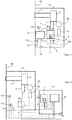
- FIG. 1 shows an example of an electronic lock assembly according to the invention.
- the electronic lock assembly comprises a latch 1, a dead lock mechanism 2 for the latch, and an electric actuator 3 for unlocking and locking the electronic lock assembly.
- the electric actuator 3 is a solenoid or an electric motor.
- the dead lock mechanism 2 is connected to the latch 1, and the electric actuator 3 is connected to the dead lock mechanism for driving it from the locked state to the unlocked state and vice versa.
- the electric actuator may be connected to the dead lock mechanism directly or by means of a part/parts, for controlling it.
- the electronic lock assembly also comprises a connection 4 receiving power from an external power source and supplying it to an electric actuator 3.
- the electronic lock assembly also comprises a secondary power supply circuit 5 which is also connected to the connection 4 and comprises a capacitor unit 6 for storing reserve capacity.
- the secondary power supply circuit is connected to supply electric energy to the actuator 3 when there is a failure in the external power source or its power transmission connection, preventing the transmission of electric power to the connection 4.
- the connection may be a cable connection or a wireless connection (such as an induction connection) used for the transmission of electric power.
- the electronic lock assembly comprises a test circuit 7 for testing the capacitor unit 6.
- the test circuit 7 is arranged to connect a test load 8 ( Fig. 5 ) to the capacitor unit 6 for testing its condition, and to measure the voltage of the capacitor unit 6 before connecting the test load 8, a second time after connecting the test load, and a third time before disconnecting the test load and after the second time.
- the electronic lock assembly also comprises a control unit 9 arranged to control the test circuit 7, to calculate the ESR value and the capacitance value of the capacitor unit 6 on the basis of said measurements, and to determine the condition of the capacitor unit on the basis of these values.
- FIG. 2 shows an example of another embodiment of the electronic lock assembly.
- the electronic lock assembly comprises a separate control module 17 in addition to the lock body 16, as in the embodiment of Fig. 1 .
- the separate control module 17 makes it possible to place components in it as well.
- the control module comprises a control unit 9, a secondary power supply circuit 5, and a data transmission unit 18 which will be described in more detail later on.
- the control module comprises a control unit 9, a secondary power supply circuit 5, and a data transmission unit 18 which will be described in more detail later on.
- control unit and the capacitor unit 6 may be placed in the control module, in which case the other components of the secondary power supply circuit are placed in the lock body 16. It is also possible to place the control unit 9 alone in the control module.
- control unit and/or the capacitor unit in the control module can be electrically connected to the lock body, that is, to the components placed in it and using the control unit and/or the capacitor unit.
- Figures 1 and 2 show that the lock body comprises a front shield 19 with a slot for the latch 1.
- the lock body may also be equipped with a handle connection 20, wherein the latch 1 can be moved into the lock body by applying a handle connected thereto.
- the electronic lock assembly equipped with a handle connection may also be arranged to comprise a handle state in which the locked state of the electronic lock assembly can be switched to the unlocked state by applying the handle (i.e. by turning the handle).
- the electric actuator 3 or another electric actuator 15 is arranged to set the electronic lock assembly on or off the handle state.
- Figures 1 and 2 further show that the electronic lock assembly may also be equipped with an audio signal device 13, a light signal device 14, or a data transmission unit 18 connected to the control unit 9 and arranged to inform the user of the electronic lock assembly about the condition of the capacitor unit 6, if the capacitor unit is defective. It is cost efficient to use only one device to inform the user, but the use of more devices is possible as well.
- the audio signal device may be, for example, a buzzer or another audio device.
- the light signal device may be, for example, a LED or another light source.
- the communication unit may transfer the information about the condition of the capacitor unit to e.g. a control center for monitoring all the electronic lock assemblies of a real estate and their condition. Further, Figs.
- the electronic lock assembly may also comprise a coupling circuit 5A which may be integrated in the secondary power supply circuit 5, or it is a separate circuit connected to the secondary power supply circuit.
- the coupling circuit supplies electric power from the connection 4 to the secondary power supply circuit 5 and to the actuator/actuators.
- the control unit is also supplied with electric energy from the connection 4, although this is not presented in the drawings.
- the control unit, as well as the other electric devices of the electronic lock assembly may be arranged to be supplied with electric energy from the capacitor unit during a failure.
- the figures accompanying this description are simplified example representations, wherein the actual embodiments to be implemented in addition to the components shown in them may also comprise other components which are, however, not essential for the implementation of the invention. Thus, on the basis of this description, a person skilled in the art can manufacture an electronic lock assembly according to the invention.
- the electric power supply can be arranged directly to both the lock body 16 and the control module 17, depending on how the components of the electronic lock assembly are distributed between the lock body and the control module.
- the electric power transmission may be implemented in another way as well, for example so that electric power is supplied from the external power source merely to the control module 17, from which electric energy is transmitted further to the lock body 16.
- the control module 17 and simultaneously the components included in it, such as the control unit 9, may thus be connected to the lock body 17 and the external power source in various ways.
- the electric lock assembly may also comprise a temperature sensor 12 whose operation will be described in more detail later on.
- FIGS 3 and 4 exemplify voltage curves 21 of the capacitor unit 6 during testing, and measurements according to the invention.
- the testing period begins when a test load 8 ( Fig. 5 ) is connected to the capacitor unit at a moment of time TA.
- the testing period ends when the test load is disconnected from the capacitor unit at a moment of time TL.
- the voltage drops because a current passes through the test load.
- the voltage U TA having the lower value at the moment of time TA can be estimated by interpolation by using the values for other times of measurement and the time difference between the measurements.
- the voltage is measured for a second time slightly after connecting the test load at a moment of time T2, whereby a value U T2 is obtained.
- the voltage is also measured for a third time at a moment of time T3 slightly before disconnecting the test load at the moment of time TL, whereby a measurement value U T3 is obtained.
- the voltage curve has descended sufficiently to show a clear difference between the measurement values for the moments of time T2 and T3, which improves the accuracy of the testing.
- RL is the test load 8, i.e. the load resistance.
- the ESR value and the capacitance value for the capacitor unit can be determined by three voltage measurements.
- the measurement can be made accurate by applying, for example, the method shown in Fig. 4 .
- the measurement of the voltage of the capacitor unit 6 before connecting the test load 8, a second time slightly after connecting the test load, and a third time slightly before disconnecting the test load, can be arranged to be taken at predetermined measurement time intervals T1 P, T2P, T3P so that several voltage measurements are taken during each measurement time interval.
- the control unit 9 is arranged to calculate an average voltage from the voltage measurements of the measurement time interval, to be used as the measurement value for each measurement time interval T1 P, T2P, T3P.
- the average time of the measurement time interval may be regarded as the time of measurement.
- the measurement time interval may be, for example, 50 to 150 ms, and the number of measurements within the measurement time interval may range, for example, from 10 to 150.
- the second measurement after connecting the test load 8 may be arranged to be taken within 5 to 400 ms after connecting the test load, and said third measurement before disconnecting the test load 8 may be arranged to be taken within 5 to 300 ms before disconnecting the test load.
- the control unit 9 is arranged to apply a predetermined testing period 10 for the test circuit 7.
- the predetermined testing period may be, for example, about 1 second. When the testing period is sufficiently long, the voltage is reduced sufficiently to provide a more reliable calculation of the angular coefficient k.
- the testing period is predetermined, as are the measurement times T1, T2 and T3.
- the capacitance value of the capacitor unit is specific to the electronic lock assembly in question. As there is a corresponding number of electronic lock assemblies, the value of the capacitor unit may thus vary to a great extent between the different electronic lock assemblies.
- the testing period varies from 0.8 to 10 s in different electronic lock assemblies. In an electronic lock assembly designed for a special purpose, the testing period may also be outside this time range.
- the testing period is such that a sufficient time is left between the above-mentioned second and third measurements, to achieve accuracy for calculating the capacitance on the basis of the measurements, and on the other hand, the testing period should be maintained short so that a sufficient charge would remain in the capacitor unit after the testing period.
- the control unit 9 is thus arranged to control the test circuit 7, to calculate the ESR value and the capacitance value of the capacitor unit 6 on the basis of said measurements, and to determine the condition of the capacitor unit on the basis of these values.
- the control unit 9 is also arranged to control the test circuit 7 at certain intervals in order to test the condition of the capacitor unit 6. The interval between the tests may be, for example, 11 to 14 hours.
- the testing and the test circuit 7 are designed so that a sufficient reserve capacity is left in the capacitor unit 6 after disconnecting the test load 8.
- control unit 9 is arranged to stop the testing of the capacitor unit 6 if a fault is detected in the connection 4 to the external power source during the testing period 10.
- the capacitor unit may supply reserve power to the electric actuator outside the testing period and, if necessary, during a predetermined testing period when the test is interrupted.
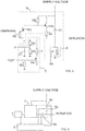
- Figures 5 and 6 show example circuit diagrams of a test circuit 7 and a secondary power supply circuit 5.
- the secondary power supply circuit may charge the capacitor unit to keep its charge at the maximum.
- the control unit 9 may monitor the secondary power supply circuit 5.
- the capacitor unit is fully charged/loaded, it does not need to be charged, and the charging may be interrupted.
- the charging is interrupted for the time of testing.
- a transistor TR2 is switched to a conducting state by the control CHARGE which is set to a suitable value by a resistor R6.
- the conducting state of the transistor TR2 changes the control of a transistor TR3 via a resistor R5, whereby the transistor TR3 will not conduct, and the charging current will not pass through a resistor R4.
- a diode D1 prevents a direct connection of the charging current to the capacitor unit.
- the test load 8 is connected to the capacitor unit 6 by supplying the transistor TR1 with a control voltage TESTI set to a suitable value by the resistance R3, whereby the transistor TR1 is switched to a conductive state, and the current can pass through the load resistance.
- the voltage measurement V of the capacitor unit is set to a suitable level by the resistors R1 and R2 and filtered by the capacitor C1.
- the capacitor unit 6 may comprise one or more capacitors 6A. If several capacitors are provided, they are connected in series and/or in parallel. The capacitor or capacitors may also be so-called supercapacitors.
- Figure 6 illustrates the connections of the test circuit 7 and the secondary power supply circuit 5 to the other components, such as the control unit 9.
- the coupling circuit 5A may be integrated in the secondary power supply circuit 5, or it is a separate circuit connected to the secondary power supply circuit.
- Figure 6 illustrates the operation of the coupling circuit by switches 5B and 5C. When the switch 5C is closed and the switch 5B is open, the actuator 3 is powered by an external power source (supply voltage marked in Figs. 5 and 6 ). When the switch 5C is open and the switch 5B is closed, the actuator is powered by the secondary power supply circuit 5.
- the representation of Fig. 6 is a reduced circuit diagram, wherein it is obvious that the structure of the coupling circuit 5A may be different from the structure shown in Fig. 6 .
- the electronic lock assembly comprises an ESR limit value and a capacitance limit value.
- the control unit 9 is arranged to compare the measured ESR value and capacitance value to the respective limit values and, in response to the comparison, to determine the condition of the capacitor unit 6.
- the limit values may thus comprise one ESR value and one capacitance value, for example 800 m ⁇ for the ESR limit value and 350 mF for the capacitance.
- the ESR and capacitance limit values to be used are thus higher when the temperature decreases.
- the limit values to be used are lower when the temperature increases.
- the limit values can be presented as values in a table, wherein the electronic lock assembly thus comprises a table of limit values.
- the electronic lock assembly may comprise a temperature sensor 12 for measuring the temperature.
- the temperature sensor is connected to the control unit 9. Because the table does not necessarily comprise said values for each different temperature but for some temperatures only, the control unit may be arranged to interpolate the ESR limit value and the capacitance limit value for the measured temperature by applying the values in the limit value table if the measured temperature is not included in the limit value table.
- the control unit may determine, on the basis of one comparison, that the capacitor unit is defective.
- the control unit may determine on the basis of one comparison that the capacitor unit is defective.
- either one of the measured ESR value and the capacitance value indicates, on the basis of the comparison, that the ESR value is too high or the capacitance value is too low.
- the user may be informed of this by an audio signal device 13, a light signal device 14, or a data transmission unit 18.
- the ESR and capacitance limit values relate to the actuator used in the electronic lock assembly, that is, for example, the power and capacity of a solenoid or an electric motor.
- the way of implementation, the structure, and the dimensioning of the test circuit are factors influencing the limit values. In other words, the limit values depend on the implementation of the electronic lock assembly.
- control unit may comprise a processor and a memory.
- the above mentioned limit values may be provided in the form of, for example, a limit value table in the memory.
- control unit may be arranged to be capable of executing the necessary control commands to provide the actuator/actuators and possibly other components with electric energy in the event of a failure in the external power supply, at least at the beginning of the failure, of shifting the electronic lock assembly to a desired state.
- the invention provides a relatively simple, robust and reliable way of measuring the condition of the capacitor unit of the electronic lock assembly without user action. Because the electronic lock assembly monitors the condition of the capacitor unit 6 by itself, the maintenance of the electronic lock assembly is easier. Consequently, the reliability and safety of the electronic lock assembly are improved, because its functionality and being in order are more secure.
- the electronic lock assembly according to the invention can be implemented by various embodiments. Consequently, the invention is not limited to the examples presented in this description, but it may be implemented in various ways within the scope of the independent claim.
Landscapes
- Engineering & Computer Science (AREA)
- Physics & Mathematics (AREA)
- General Physics & Mathematics (AREA)
- Power Engineering (AREA)
- Manufacturing & Machinery (AREA)
- Microelectronics & Electronic Packaging (AREA)
- Business, Economics & Management (AREA)
- Emergency Management (AREA)
- Testing Electric Properties And Detecting Electric Faults (AREA)
Abstract
Description
- The invention relates to an electronic lock assembly supplied from an external power source. The external power source supplies the actuator or actuators of the electronic lock assembly with the energy needed for driving the electronic lock assembly from a locked state to an unlocked state, and vice versa.
- It is well known to apply an external power source for supplying electric energy to an electronic lock assembly, to provide the electric actuator or actuators with the energy needed. The electric actuator is, for example, a solenoid or an electric motor connected to a dead lock mechanism. The dead lock mechanism may be driven from the locked state to the unlocked state and vice versa by the electric actuator or electric actuators. The unlocked state refers to the state in which the latch of the electronic lock mechanism can withdraw into the lock body without being prevented by the dead lock mechanism. The locked state means that the dead lock mechanism prevents the withdrawal of the latch into the lock body, whereby the part of the latch protruding from the lock body locks, for example, a door in which the lock body is installed, against the jamb of the door.
- Furthermore, the electronic lock assembly may comprise a handle state in which the locked state can be switched to the unlocked state by applying a handle. Thus, applying the handle connected to the lock body will unlock the lock from the locked state to the unlocked state. The electric actuator or a second electric actuator is arranged to set the electronic lock assembly on or off the handle state.
- The electronic lock assembly thus comprises an input connection receiving power from an external power source and supplying it to an electric actuator or electric actuators. In the event of a failure in the power source or the power transmission connection between the electronic lock assembly and the power source, during which no electric power can be supplied to the electronic lock assembly, this failure can be detected at the connection of the external power source. For such situations, the electronic lock assembly may also comprise a secondary power supply circuit connected to the input connection and comprising a capacitor unit for storing reserve power. Electric energy stored by the capacitor unit of the secondary power supply circuit may be used in the electronic lock assembly when no electric energy is supplied by the external power source.
- The charging capacity of the capacitor unit may be reduced upon ageing. Although capacitors have a relatively long service life, their charging capacity may be reduced over time to such an extent that they can no longer function properly. Consequently, an old capacitor unit in the electronic lock assembly may no longer be capable of charging a sufficient amount of electric energy to meet the power demand of the electric actuator during a failure of the external power source. This may cause danger situations in safety when the electronic lock assembly cannot be driven to the locked state or the unlocked state. The user of the electronic lock assembly should inspect the condition of the capacitor unit manually every now and then. This is not always observed, whereby it is first in the event of a failure that lock maintenance is called in.
- The aim of the invention is to provide an electronic lock assembly in which the condition of the capacitor unit is monitored by the electronic lock assembly itself. Thus, no particular monitoring measures need to be taken by the user of the electronic lock assembly. Possible danger situations in safety can be foreseen, whereby it is possible to avoid them or at least to minimize their effect. This is achieved in the way presented in the independent claim. The dependent claims describe various embodiments of the invention.
- The electronic lock assembly according to the invention comprises a
latch 1, adead lock mechanism 2 for the latch, and anelectric actuator 3 for unlocking and locking the electronic lock assembly. Thedead lock mechanism 2 is connected to thelatch 1, and theelectric actuator 3 is connected to the dead lock mechanism for controlling it from the locked state to the unlocked state and vice versa. The electronic lock assembly also comprises aconnection 4 receiving power from an external power source, the connection being connected to anelectric actuator 3 and a secondarypower supply circuit 5. The secondary power supply circuit comprises acapacitor unit 6 for storing reserve capacity. - The electronic lock assembly also comprises a
test circuit 7 for testing thecapacitor unit 6. Thetest circuit 7 is arranged to connect a test load 8 to thecapacitor unit 6 for testing its condition, and to measure the voltage of thecapacitor unit 6 before connecting the test load 8, slightly after connecting the test load, and slightly before disconnecting the test load. - The electronic lock assembly further comprises a
control unit 9 arranged to control thetest circuit 7, to calculate the ESR (equivalent serial resistance) value and the capacitance value of thecapacitor unit 6 on the basis of said measurements, and to determine the condition of the capacitor unit on the basis of these values. - In the following, the invention will be described in more detail with reference to the appended figures, in which
- Fig. 1
- shows an example of an electronic lock assembly according to the invention,
- Fig. 2
- shows another example of an electronic lock assembly according to the invention,
- Fig. 3
- shows an example of a voltage curve of the capacitor unit and of a measurement according to the invention,
- Fig. 4
- shows another example of a voltage curve of the capacitor unit and of a measurement according to the invention,
- Fig. 5
- shows an example of a circuit chart on testing of a capacitor unit according to the invention, and
- Fig. 6
- shows another example of circuit chart on testing of a capacitor unit according to the invention.
-
Figure 1 shows an example of an electronic lock assembly according to the invention. The electronic lock assembly comprises alatch 1, adead lock mechanism 2 for the latch, and anelectric actuator 3 for unlocking and locking the electronic lock assembly. Theelectric actuator 3 is a solenoid or an electric motor. Thedead lock mechanism 2 is connected to thelatch 1, and theelectric actuator 3 is connected to the dead lock mechanism for driving it from the locked state to the unlocked state and vice versa. The electric actuator may be connected to the dead lock mechanism directly or by means of a part/parts, for controlling it. - The electronic lock assembly also comprises a
connection 4 receiving power from an external power source and supplying it to anelectric actuator 3. The electronic lock assembly also comprises a secondarypower supply circuit 5 which is also connected to theconnection 4 and comprises acapacitor unit 6 for storing reserve capacity. The secondary power supply circuit is connected to supply electric energy to theactuator 3 when there is a failure in the external power source or its power transmission connection, preventing the transmission of electric power to theconnection 4. The connection may be a cable connection or a wireless connection (such as an induction connection) used for the transmission of electric power. - The electronic lock assembly comprises a
test circuit 7 for testing thecapacitor unit 6. Thetest circuit 7 is arranged to connect a test load 8 (Fig. 5 ) to thecapacitor unit 6 for testing its condition, and to measure the voltage of thecapacitor unit 6 before connecting the test load 8, a second time after connecting the test load, and a third time before disconnecting the test load and after the second time. The electronic lock assembly also comprises acontrol unit 9 arranged to control thetest circuit 7, to calculate the ESR value and the capacitance value of thecapacitor unit 6 on the basis of said measurements, and to determine the condition of the capacitor unit on the basis of these values. -
Figure 2 shows an example of another embodiment of the electronic lock assembly. In this embodiment, the electronic lock assembly comprises aseparate control module 17 in addition to thelock body 16, as in the embodiment ofFig. 1 . After all the components mentioned above, and also other components yet unmentioned, have been accommodated in the lock body of the embodiment ofFig. 1 , theseparate control module 17 makes it possible to place components in it as well. In the example ofFig. 2 , the control module comprises acontrol unit 9, a secondarypower supply circuit 5, and adata transmission unit 18 which will be described in more detail later on. Naturally, it is also possible to distribute components between the control module and the lock body in another way as well. For example, the control unit and thecapacitor unit 6 may be placed in the control module, in which case the other components of the secondary power supply circuit are placed in thelock body 16. It is also possible to place thecontrol unit 9 alone in the control module. For example, the control unit and/or the capacitor unit in the control module can be electrically connected to the lock body, that is, to the components placed in it and using the control unit and/or the capacitor unit. -
Figures 1 and 2 show that the lock body comprises afront shield 19 with a slot for thelatch 1. The lock body may also be equipped with ahandle connection 20, wherein thelatch 1 can be moved into the lock body by applying a handle connected thereto. The electronic lock assembly equipped with a handle connection may also be arranged to comprise a handle state in which the locked state of the electronic lock assembly can be switched to the unlocked state by applying the handle (i.e. by turning the handle). In an electronic lock assembly comprising a handle state, theelectric actuator 3 or anotherelectric actuator 15 is arranged to set the electronic lock assembly on or off the handle state. -
Figures 1 and 2 further show that the electronic lock assembly may also be equipped with anaudio signal device 13, alight signal device 14, or adata transmission unit 18 connected to thecontrol unit 9 and arranged to inform the user of the electronic lock assembly about the condition of thecapacitor unit 6, if the capacitor unit is defective. It is cost efficient to use only one device to inform the user, but the use of more devices is possible as well. The audio signal device may be, for example, a buzzer or another audio device. The light signal device may be, for example, a LED or another light source. The communication unit may transfer the information about the condition of the capacitor unit to e.g. a control center for monitoring all the electronic lock assemblies of a real estate and their condition. Further,Figs. 1 and 2 show that the electronic lock assembly may also comprise acoupling circuit 5A which may be integrated in the secondarypower supply circuit 5, or it is a separate circuit connected to the secondary power supply circuit. The coupling circuit supplies electric power from theconnection 4 to the secondarypower supply circuit 5 and to the actuator/actuators. It is convenient that the control unit is also supplied with electric energy from theconnection 4, although this is not presented in the drawings. The control unit, as well as the other electric devices of the electronic lock assembly, may be arranged to be supplied with electric energy from the capacitor unit during a failure. The figures accompanying this description are simplified example representations, wherein the actual embodiments to be implemented in addition to the components shown in them may also comprise other components which are, however, not essential for the implementation of the invention. Thus, on the basis of this description, a person skilled in the art can manufacture an electronic lock assembly according to the invention. - As can be seen from
Fig. 2 , the electric power supply can be arranged directly to both thelock body 16 and thecontrol module 17, depending on how the components of the electronic lock assembly are distributed between the lock body and the control module. The electric power transmission may be implemented in another way as well, for example so that electric power is supplied from the external power source merely to thecontrol module 17, from which electric energy is transmitted further to thelock body 16. Thecontrol module 17 and simultaneously the components included in it, such as thecontrol unit 9, may thus be connected to thelock body 17 and the external power source in various ways. - The electric lock assembly may also comprise a
temperature sensor 12 whose operation will be described in more detail later on. -
Figures 3 and 4 exemplify voltage curves 21 of thecapacitor unit 6 during testing, and measurements according to the invention. Before the actual testing period 10, the voltage of thecapacitor unit 6 is measured, in the example ofFig. 3 at a moment of time T1. The testing period begins when a test load 8 (Fig. 5 ) is connected to the capacitor unit at a moment of time TA. The testing period ends when the test load is disconnected from the capacitor unit at a moment of time TL. When the test load is connected at the moment of time TA, the voltage drops because a current passes through the test load. Let us assume that the current is constant, whereby the voltage change is
- The voltage UTA having the lower value at the moment of time TA can be estimated by interpolation by using the values for other times of measurement and the time difference between the measurements. The voltage is measured for a second time slightly after connecting the test load at a moment of time T2, whereby a value UT2 is obtained. The voltage is also measured for a third time at a moment of time T3 slightly before disconnecting the test load at the moment of time TL, whereby a measurement value UT3 is obtained. Between the measurement times T2 and T3, the voltage curve has descended sufficiently to show a clear difference between the measurement values for the moments of time T2 and T3, which improves the accuracy of the testing. The measurements provide an angular coefficient


- Let us assume that the current I remains constant during the whole measurement, and it passes through the test load. When the
formula 1 is applied as a formula for the voltage of the test load as well, the value RESR can be derived from the formula
- where RL is the test load 8, i.e. the load resistance.
- By applying the angular coefficient k, the capacitance is obtained from the formula

- As can be seen, the ESR value and the capacitance value for the capacitor unit can be determined by three voltage measurements. The measurement can be made accurate by applying, for example, the method shown in
Fig. 4 . - The measurement of the voltage of the
capacitor unit 6 before connecting the test load 8, a second time slightly after connecting the test load, and a third time slightly before disconnecting the test load, can be arranged to be taken at predetermined measurement time intervals T1 P, T2P, T3P so that several voltage measurements are taken during each measurement time interval. Thecontrol unit 9 is arranged to calculate an average voltage from the voltage measurements of the measurement time interval, to be used as the measurement value for each measurement time interval T1 P, T2P, T3P. In such a method, the average time of the measurement time interval may be regarded as the time of measurement. Thus, in the method according toFig. 4 , it is possible to reduce the effect of an error, such as measurement noise, in a single measurement. - The measurement time interval may be, for example, 50 to 150 ms, and the number of measurements within the measurement time interval may range, for example, from 10 to 150. The second measurement after connecting the test load 8 may be arranged to be taken within 5 to 400 ms after connecting the test load, and said third measurement before disconnecting the test load 8 may be arranged to be taken within 5 to 300 ms before disconnecting the test load. The
control unit 9 is arranged to apply a predetermined testing period 10 for thetest circuit 7. The predetermined testing period may be, for example, about 1 second. When the testing period is sufficiently long, the voltage is reduced sufficiently to provide a more reliable calculation of the angular coefficient k. The testing period is predetermined, as are the measurement times T1, T2 and T3. - Because the actuator/actuators of the electronic lock assembly affect the size and the charging capacity required of the capacitor unit in order to supply sufficient electric energy in the event of a failure, the capacitance value of the capacitor unit is specific to the electronic lock assembly in question. As there is a corresponding number of electronic lock assemblies, the value of the capacitor unit may thus vary to a great extent between the different electronic lock assemblies.
- Consequently, the capacitor unit and thereby also the load resistance influence the testing period as well, which is thus also specific to the electronic lock assembly in question. The testing period varies from 0.8 to 10 s in different electronic lock assemblies. In an electronic lock assembly designed for a special purpose, the testing period may also be outside this time range.
- Thus, the testing period is such that a sufficient time is left between the above-mentioned second and third measurements, to achieve accuracy for calculating the capacitance on the basis of the measurements, and on the other hand, the testing period should be maintained short so that a sufficient charge would remain in the capacitor unit after the testing period.
- The
control unit 9 is thus arranged to control thetest circuit 7, to calculate the ESR value and the capacitance value of thecapacitor unit 6 on the basis of said measurements, and to determine the condition of the capacitor unit on the basis of these values. Thecontrol unit 9 is also arranged to control thetest circuit 7 at certain intervals in order to test the condition of thecapacitor unit 6. The interval between the tests may be, for example, 11 to 14 hours. - The testing and the
test circuit 7 are designed so that a sufficient reserve capacity is left in thecapacitor unit 6 after disconnecting the test load 8. - Moreover, the
control unit 9 is arranged to stop the testing of thecapacitor unit 6 if a fault is detected in theconnection 4 to the external power source during the testing period 10. In other words, the capacitor unit may supply reserve power to the electric actuator outside the testing period and, if necessary, during a predetermined testing period when the test is interrupted. -
Figures 5 and 6 show example circuit diagrams of atest circuit 7 and a secondarypower supply circuit 5. When thecapacitor unit 6 is not being tested, the secondary power supply circuit may charge the capacitor unit to keep its charge at the maximum. Thecontrol unit 9 may monitor the secondarypower supply circuit 5. When the capacitor unit is fully charged/loaded, it does not need to be charged, and the charging may be interrupted. The charging is interrupted for the time of testing. When charging is interrupted in the embodiment according to the example ofFig. 5 , a transistor TR2 is switched to a conducting state by the control CHARGE which is set to a suitable value by a resistor R6. The conducting state of the transistor TR2 changes the control of a transistor TR3 via a resistor R5, whereby the transistor TR3 will not conduct, and the charging current will not pass through a resistor R4. A diode D1 prevents a direct connection of the charging current to the capacitor unit. - When the capacitor unit is being tested, its charging is prevented. The test load 8 is connected to the
capacitor unit 6 by supplying the transistor TR1 with a control voltage TESTI set to a suitable value by the resistance R3, whereby the transistor TR1 is switched to a conductive state, and the current can pass through the load resistance. The voltage measurement V of the capacitor unit is set to a suitable level by the resistors R1 and R2 and filtered by the capacitor C1. It should be noted that thecapacitor unit 6 may comprise one ormore capacitors 6A. If several capacitors are provided, they are connected in series and/or in parallel. The capacitor or capacitors may also be so-called supercapacitors. -
Figure 6 illustrates the connections of thetest circuit 7 and the secondarypower supply circuit 5 to the other components, such as thecontrol unit 9. As described above, thecoupling circuit 5A may be integrated in the secondarypower supply circuit 5, or it is a separate circuit connected to the secondary power supply circuit.Figure 6 illustrates the operation of the coupling circuit byswitches switch 5C is closed and theswitch 5B is open, theactuator 3 is powered by an external power source (supply voltage marked inFigs. 5 and 6 ). When theswitch 5C is open and theswitch 5B is closed, the actuator is powered by the secondarypower supply circuit 5. The representation ofFig. 6 is a reduced circuit diagram, wherein it is obvious that the structure of thecoupling circuit 5A may be different from the structure shown inFig. 6 . - The electronic lock assembly comprises an ESR limit value and a capacitance limit value. The
control unit 9 is arranged to compare the measured ESR value and capacitance value to the respective limit values and, in response to the comparison, to determine the condition of thecapacitor unit 6. In the simplest form, the limit values may thus comprise one ESR value and one capacitance value, for example 800 mΩ for the ESR limit value and 350 mF for the capacitance. To enhance the accuracy, however, it is possible to comprise ESR limit values and capacitance limit values for different temperatures. The ESR and capacitance limit values to be used are thus higher when the temperature decreases. Correspondingly, the limit values to be used are lower when the temperature increases. The limit values can be presented as values in a table, wherein the electronic lock assembly thus comprises a table of limit values. To make use of the limit values for the different temperatures, the electronic lock assembly may comprise atemperature sensor 12 for measuring the temperature. The temperature sensor is connected to thecontrol unit 9. Because the table does not necessarily comprise said values for each different temperature but for some temperatures only, the control unit may be arranged to interpolate the ESR limit value and the capacitance limit value for the measured temperature by applying the values in the limit value table if the measured temperature is not included in the limit value table. - If the measured ESR value is higher than the ESR limit value, the control unit may determine, on the basis of one comparison, that the capacitor unit is defective. Correspondingly, if the measured capacitance value is lower than the limit value for the capacitance, the control unit may determine on the basis of one comparison that the capacitor unit is defective. However, it is safer that the
control unit 9 is arranged to apply several measurements for determining a change in the condition of thecapacitor unit 6 from a functional capacitor unit to a defective capacitor unit. For example, if six comparisons in succession indicate that the capacitor unit is defective, it is first then that the capacitor unit is determined to be defective. For indicating a defect, it is sufficient that either one of the measured ESR value and the capacitance value indicates, on the basis of the comparison, that the ESR value is too high or the capacitance value is too low. After the capacitor unit has been determined to be defective, the user may be informed of this by anaudio signal device 13, alight signal device 14, or adata transmission unit 18. - The ESR and capacitance limit values relate to the actuator used in the electronic lock assembly, that is, for example, the power and capacity of a solenoid or an electric motor. The way of implementation, the structure, and the dimensioning of the test circuit are factors influencing the limit values. In other words, the limit values depend on the implementation of the electronic lock assembly.
- It is convenient to implement the control unit to comprise a processor and a memory. The above mentioned limit values may be provided in the form of, for example, a limit value table in the memory. Furthermore, the control unit may be arranged to be capable of executing the necessary control commands to provide the actuator/actuators and possibly other components with electric energy in the event of a failure in the external power supply, at least at the beginning of the failure, of shifting the electronic lock assembly to a desired state.
- The invention provides a relatively simple, robust and reliable way of measuring the condition of the capacitor unit of the electronic lock assembly without user action. Because the electronic lock assembly monitors the condition of the
capacitor unit 6 by itself, the maintenance of the electronic lock assembly is easier. Consequently, the reliability and safety of the electronic lock assembly are improved, because its functionality and being in order are more secure. - The electronic lock assembly according to the invention can be implemented by various embodiments. Consequently, the invention is not limited to the examples presented in this description, but it may be implemented in various ways within the scope of the independent claim.
Claims (19)
- An electronic lock assembly comprising a latch (1), a dead lock mechanism (2) of the latch, and an electric actuator (3) to unlock and to lock the electronic lock assembly, the dead lock mechanism (2) being connected to the latch (1), and the electric actuator (3) being connected to the dead lock mechanism to drive it from the locked state to the unlocked state and vice versa,
the electronic lock assembly further comprising a connection (4) to an external power source, the connection being connected to the electric actuator (3),
the electronic lock assembly further comprising a secondary power supply circuit (5) connected to the connection (4) and comprising a capacitor unit (6) to store reserve capacity,
characterized in that the electronic lock assembly comprises a test circuit (7) to test the capacitor unit (6), the test circuit (7) being arranged to couple a test load (8) on the capacitor unit (6) in order to test its condition, and to measure the voltage of the capacitor unit (6) before connecting the test load (8), a second time after connecting the test load, and a third time before disconnecting the test load and after the second time,
the electronic lock assembly comprising a control unit (9) arranged to control the test circuit (7), to calculate the ESR value and the capacitance value of the capacitor unit (6) on the basis of said measurements, and to determine the condition of the capacitor unit on the basis of these values. - The electronic lock assembly according to claim 1, characterized in that the control unit (9) is arranged to apply a predetermined testing period (10) for the test circuit (7).
- The electronic lock assembly according to claim 1 or 2, characterized in that the limit values comprise ESR limit values and capacitance limit values for different temperatures,
the control unit (9) being arranged to compare the measured ESR value and capacitance value to the respective limit values and, in response to the comparison, to determine the condition of the capacitor unit (6). - The electronic lock assembly according to claim 3, characterized in that it comprises a limit value table comprising ESR and capacitance limit values.
- The electronic lock assembly according to claim 3 or 4, characterized in that the electronic lock assembly comprises a temperature sensor (12) to measure the temperature, the temperature sensor being connected to the control unit (9), and the control unit being arranged to interpolate the ESR limit value and the capacitance limit value for the measured temperature by using limit values if the measured temperature is not included in the limit values.
- The electronic lock assembly according to claim 5, characterized in that the control unit (9) is arranged to apply several measurements in order to determine a change in the condition of the capacitor unit (6) from a functional capacitor unit to a defective capacitor unit.
- The electronic lock assembly according to any of the claims 2 to 6, characterized in that the control unit (9) is arranged to control the test circuit (7) at given intervals, to test the condition of the capacitor unit (6).
- The electronic lock assembly according to claim 7, characterized in that the test circuit (7) is dimensioned so that a sufficient reserve capacity is left in the capacitor unit (6) after disconnecting the test load (8).
- The electronic lock assembly according to claim 8, characterized in that the control unit (9) is arranged to stop the testing of the capacitor unit (6) if a fault is detected in the connection (4) to the external power source during the testing period (10).
- The electronic lock assembly according to any of the claims 1 to 9, characterized in that the electronic lock assembly comprises an audio signal device (13), a light signal device (14), or a data transmission unit (18) connected to the control unit (9) and arranged to inform the user of the electronic lock assembly about the condition of the capacitor unit (6), if the capacitor unit is defective.
- The electronic lock assembly according to any of the claims 2 to 10, characterized in that the predetermined testing period (10) is 0.8 to 10 seconds.
- The electronic lock assembly according to claim 11, characterized in that the measurements of the voltage of the capacitor unit (6) before connecting the test load (8), a second time slightly after connecting the test load, and a third time slightly before disconnecting the test load, are arranged to be taken at predetermined measurement intervals T1 P, T2P, T3P so that several voltage measurements are taken during each measurement interval, from which the control unit (9) is arranged to calculate an average voltage to be used as the measurement value for each measurement interval T1P, T2P, T3P.
- The electronic lock assembly according to any of the claims 2 to 12, characterized in that said second measurement after connecting the test load (8) is arranged to be taken within 5 to 400 ms after connecting the test load, and said third measurement before disconnecting the test load (8) is arranged to be taken within 5 to 300 ms before disconnecting the test load.
- The electronic lock assembly according to any of the claims 2 to 13, characterized in that the capacitor unit (6) comprises at least one capacitor.
- The electronic lock assembly according to claim 14, characterized in that the electric actuator (3) is a solenoid or an electric motor.
- The electronic lock assembly according to any of the claims 2 to 15, characterized in that the electronic lock assembly is arranged to comprise a handle state, in which the locked state is controllable by the handle to an unlocked state, and the electric actuator (3) or a second electric actuator (15) is arranged to drive the electronic lock assembly on or off the handle state.
- The electronic lock assembly according to any of the claims 1 to 16, characterized in that the electronic lock assembly comprises a lock body (16) accommodating said components of the electronic lock assembly.
- The electronic lock assembly according to any of the claims 1 to 16, characterized in that the electronic lock assembly comprises a lock body (16) and a separate control module (17), in which control module the control unit (9) and the capacitor unit (6) are accommodated, and which control unit and capacitor unit are electrically connectable to the lock body, to the components accommodated in it and using the control unit and the capacitor unit.
- The electronic lock assembly according to any of the claims 1 to 16, characterized in that the electronic lock assembly comprises a lock body (16) and a separate control module (17), in which control module the control unit (9) is accommodated, and which control unit is electrically connectable to the lock body, to the components accommodated in it and using the control unit.
Applications Claiming Priority (1)
| Application Number | Priority Date | Filing Date | Title |
|---|---|---|---|
| FI20175461A FI128211B (en) | 2017-05-23 | 2017-05-23 | ELECTRIC LOCK ARRANGEMENT |
Publications (2)
| Publication Number | Publication Date |
|---|---|
| EP3407308A1 true EP3407308A1 (en) | 2018-11-28 |
| EP3407308B1 EP3407308B1 (en) | 2021-06-30 |
Family
ID=62063425
Family Applications (1)
| Application Number | Title | Priority Date | Filing Date |
|---|---|---|---|
| EP18169283.1A Active EP3407308B1 (en) | 2017-05-23 | 2018-04-25 | Electronic lock assembly |
Country Status (4)
| Country | Link |
|---|---|
| US (1) | US11220843B2 (en) |
| EP (1) | EP3407308B1 (en) |
| CN (1) | CN108930453B (en) |
| FI (1) | FI128211B (en) |
Cited By (1)
| Publication number | Priority date | Publication date | Assignee | Title |
|---|---|---|---|---|
| EP3771382B1 (en) * | 2019-07-30 | 2024-04-17 | BSH Hausgeräte GmbH | Home appliance with system for operating a latch device |
Families Citing this family (14)
| Publication number | Priority date | Publication date | Assignee | Title |
|---|---|---|---|---|
| US11180929B2 (en) * | 2017-09-19 | 2021-11-23 | Sargent Manufacturing Company | Low temperature control of lock actuator |
| US10693310B2 (en) * | 2017-10-31 | 2020-06-23 | Sargent Manufacturing Company | Hiccup charger |
| CN111505524B (en) * | 2019-01-30 | 2022-09-23 | 台达电子工业股份有限公司 | On-line monitoring method of cascade converter and applicable cascade converter |
| US11639617B1 (en) | 2019-04-03 | 2023-05-02 | The Chamberlain Group Llc | Access control system and method |
| CA3087386A1 (en) | 2019-07-18 | 2021-01-18 | Endura Products, Llc | Methods of operating a lock |
| EP4047167A1 (en) | 2021-02-19 | 2022-08-24 | Face S.r.l. | Electronic system to activate the emergency opening and/or closing of automatic doors |
| WO2022214347A1 (en) | 2021-04-09 | 2022-10-13 | Assa Abloy Ab | Finding faults in firmware for a lock device |
| US12018516B2 (en) * | 2021-06-30 | 2024-06-25 | Delta Cycle Corporation | Electronic lock |
| US12024924B2 (en) | 2021-07-01 | 2024-07-02 | Delta Cycle Corporation | Electronic lock |
| US12060733B2 (en) | 2021-08-16 | 2024-08-13 | Delta Cycle Corporation | Bicycle cable lock |
| WO2023177702A1 (en) * | 2022-03-15 | 2023-09-21 | Cantaloupe, Inc. | Locking system and method for a temperature-controlled container |
| US20240410208A1 (en) * | 2023-06-09 | 2024-12-12 | Command Access Technology, Inc. | Cylindrical lock with motor-driven latch |
| EP4575149A1 (en) * | 2023-12-21 | 2025-06-25 | iLOQ Oy | Electromechanical lock and method of powering electromechanical lock |
| WO2026033153A1 (en) * | 2024-08-06 | 2026-02-12 | Montajes Electronicos Dorcas, S.L. | Locking device comprising a preload protection system |
Citations (3)
| Publication number | Priority date | Publication date | Assignee | Title |
|---|---|---|---|---|
| EP2016243A1 (en) * | 2006-05-02 | 2009-01-21 | Abloy Oy | Lock body |
| US20150171664A1 (en) * | 2013-12-13 | 2015-06-18 | Lite-On Electronics (Guangzhou) Limited | Power supply system and control method thereof |
| WO2015183250A1 (en) * | 2014-05-28 | 2015-12-03 | Schneider Electric Buildings Llc | Estimation of the remaining lifetime of a supercapacitor |
Family Cites Families (13)
| Publication number | Priority date | Publication date | Assignee | Title |
|---|---|---|---|---|
| US4967305A (en) * | 1989-01-06 | 1990-10-30 | Datatrak, Inc. | Electronic door lock apparatus, system and method |
| US6005487A (en) * | 1990-05-11 | 1999-12-21 | Medeco Security Locks, Inc. | Electronic security system with novel electronic T-handle lock |
| JP3850311B2 (en) * | 2002-02-21 | 2006-11-29 | オムロン株式会社 | Remaining life prediction notification method and electronic device |
| US7487391B2 (en) * | 2005-08-04 | 2009-02-03 | Dot Hill Systems Corporation | Storage controller super capacitor adaptive life monitor |
| US8154259B2 (en) * | 2007-07-25 | 2012-04-10 | Agiga Tech Inc. | Capacitor save energy verification |
| US8065562B2 (en) * | 2009-06-26 | 2011-11-22 | Seagate Technology Llc | Systems, methods and devices for backup power control in data storage devices |
| US8607076B2 (en) * | 2009-06-26 | 2013-12-10 | Seagate Technology Llc | Circuit apparatus with memory and power control responsive to circuit-based deterioration characteristics |
| CN104054233B (en) | 2012-01-16 | 2017-05-03 | 施耐德电气建筑有限公司 | Regulation of Capacitor Charging Voltage |
| DE112013006196T5 (en) * | 2012-12-24 | 2015-09-10 | Magna Closures Inc. | Accident management system and method in an electronic lock of a motor vehicle locking device |
| US9673868B2 (en) * | 2013-05-16 | 2017-06-06 | Microchip Technology Incorporated | Wireless door lock power transfer system having communications capabilities |
| CN203662263U (en) | 2014-01-14 | 2014-06-25 | 厦门汉凌达智能科技有限公司 | Express dispatching cabinet |
| US9567773B2 (en) * | 2014-02-25 | 2017-02-14 | Schlage Lock Company Llc | Electronic lock with selectable power off function |
| US9740258B2 (en) * | 2014-03-24 | 2017-08-22 | Intel Corporation | Hold-up energy storage and management |
-
2017
- 2017-05-23 FI FI20175461A patent/FI128211B/en active IP Right Grant
-
2018
- 2018-04-25 EP EP18169283.1A patent/EP3407308B1/en active Active
- 2018-05-23 US US15/987,592 patent/US11220843B2/en active Active
- 2018-05-23 CN CN201810500569.2A patent/CN108930453B/en active Active
Patent Citations (3)
| Publication number | Priority date | Publication date | Assignee | Title |
|---|---|---|---|---|
| EP2016243A1 (en) * | 2006-05-02 | 2009-01-21 | Abloy Oy | Lock body |
| US20150171664A1 (en) * | 2013-12-13 | 2015-06-18 | Lite-On Electronics (Guangzhou) Limited | Power supply system and control method thereof |
| WO2015183250A1 (en) * | 2014-05-28 | 2015-12-03 | Schneider Electric Buildings Llc | Estimation of the remaining lifetime of a supercapacitor |
Cited By (1)
| Publication number | Priority date | Publication date | Assignee | Title |
|---|---|---|---|---|
| EP3771382B1 (en) * | 2019-07-30 | 2024-04-17 | BSH Hausgeräte GmbH | Home appliance with system for operating a latch device |
Also Published As
| Publication number | Publication date |
|---|---|
| EP3407308B1 (en) | 2021-06-30 |
| CN108930453A (en) | 2018-12-04 |
| US11220843B2 (en) | 2022-01-11 |
| FI20175461A1 (en) | 2018-11-24 |
| FI128211B (en) | 2019-12-31 |
| FI20175461A7 (en) | 2018-11-24 |
| US20180340351A1 (en) | 2018-11-29 |
| CN108930453B (en) | 2022-04-05 |
Similar Documents
| Publication | Publication Date | Title |
|---|---|---|
| EP3407308B1 (en) | Electronic lock assembly | |
| CN106896274B (en) | Apparatus, system and method for insulation resistance measurement and insulation loss diagnosis | |
| EP4022737B1 (en) | Location-determinant fault monitoring for battery management system | |
| US11545839B2 (en) | System for charging a series of connected batteries | |
| JP5705382B1 (en) | Insulation detector and electrical equipment | |
| US10209311B2 (en) | Switching state of a mechanical switch | |
| KR102044559B1 (en) | Electric storage device and power route switching device | |
| US12467966B2 (en) | Apparatus and method for diagnosing insulation resistance measurement circuit | |
| US9876261B2 (en) | Monitoring device for a battery, a lithium-ion battery, and method for the monitoring of a battery | |
| CN106785107B (en) | For diagnosing the method and system of battery system problem | |
| DE112013006192T5 (en) | Auxiliary power source for vehicle systems and associated control method | |
| EP1181540A1 (en) | Electronic battery tester | |
| DE112006002329B4 (en) | Diagnostic device for automotive electrical systems | |
| JP7542554B2 (en) | Electric leakage detection device, vehicle power supply system | |
| KR102324968B1 (en) | System and method for diagnosing the connectivity of fuses, bms including a system for diagnosing the connectivity of fuses | |
| DE102009006570B4 (en) | Method and circuit for monitoring an emergency power accumulator of a hazard alarm system | |
| US12230995B2 (en) | Auxiliary power supply device and method for controlling auxiliary power supply device | |
| CN110691709B (en) | Methods and devices for operating electrical energy storage systems and electrical energy storage systems having the devices and corresponding uses | |
| CN107403970B (en) | Energy storage unit for a motor vehicle and method of installing an energy storage unit | |
| RU2594648C2 (en) | Method and device for diagnostics of drive mechanism and drive mechanism containing one such device | |
| CN115812154B (en) | Methods and apparatus for monitoring low-pass filters, as well as battery management systems, batteries, and vehicles. | |
| CN120972006A (en) | Anomaly identification methods, devices, and non-volatile storage media for battery management systems | |
| DE102012200964A1 (en) | Monitoring device, battery cell and method for monitoring a battery cell | |
| GB2536919A (en) | System and method for automated battery testing |
Legal Events
| Date | Code | Title | Description |
|---|---|---|---|
| PUAI | Public reference made under article 153(3) epc to a published international application that has entered the european phase |
Free format text: ORIGINAL CODE: 0009012 |
|
| STAA | Information on the status of an ep patent application or granted ep patent |
Free format text: STATUS: THE APPLICATION HAS BEEN PUBLISHED |
|
| AK | Designated contracting states |
Kind code of ref document: A1 Designated state(s): AL AT BE BG CH CY CZ DE DK EE ES FI FR GB GR HR HU IE IS IT LI LT LU LV MC MK MT NL NO PL PT RO RS SE SI SK SM TR |
|
| AX | Request for extension of the european patent |
Extension state: BA ME |
|
| STAA | Information on the status of an ep patent application or granted ep patent |
Free format text: STATUS: REQUEST FOR EXAMINATION WAS MADE |
|
| 17P | Request for examination filed |
Effective date: 20190522 |
|
| RBV | Designated contracting states (corrected) |
Designated state(s): AL AT BE BG CH CY CZ DE DK EE ES FI FR GB GR HR HU IE IS IT LI LT LU LV MC MK MT NL NO PL PT RO RS SE SI SK SM TR |
|
| GRAP | Despatch of communication of intention to grant a patent |
Free format text: ORIGINAL CODE: EPIDOSNIGR1 |
|
| STAA | Information on the status of an ep patent application or granted ep patent |
Free format text: STATUS: GRANT OF PATENT IS INTENDED |
|
| INTG | Intention to grant announced |
Effective date: 20210122 |
|
| GRAS | Grant fee paid |
Free format text: ORIGINAL CODE: EPIDOSNIGR3 |
|
| GRAA | (expected) grant |
Free format text: ORIGINAL CODE: 0009210 |
|
| STAA | Information on the status of an ep patent application or granted ep patent |
Free format text: STATUS: THE PATENT HAS BEEN GRANTED |
|
| AK | Designated contracting states |
Kind code of ref document: B1 Designated state(s): AL AT BE BG CH CY CZ DE DK EE ES FI FR GB GR HR HU IE IS IT LI LT LU LV MC MK MT NL NO PL PT RO RS SE SI SK SM TR |
|
| REG | Reference to a national code |
Ref country code: CH Ref legal event code: EP |
|
| REG | Reference to a national code |
Ref country code: DE Ref legal event code: R096 Ref document number: 602018019187 Country of ref document: DE Ref country code: AT Ref legal event code: REF Ref document number: 1407056 Country of ref document: AT Kind code of ref document: T Effective date: 20210715 |
|
| REG | Reference to a national code |
Ref country code: IE Ref legal event code: FG4D |
|
| REG | Reference to a national code |
Ref country code: LT Ref legal event code: MG9D |
|
| REG | Reference to a national code |
Ref country code: SE Ref legal event code: TRGR |
|
| PG25 | Lapsed in a contracting state [announced via postgrant information from national office to epo] |
Ref country code: FI Free format text: LAPSE BECAUSE OF FAILURE TO SUBMIT A TRANSLATION OF THE DESCRIPTION OR TO PAY THE FEE WITHIN THE PRESCRIBED TIME-LIMIT Effective date: 20210630 Ref country code: HR Free format text: LAPSE BECAUSE OF FAILURE TO SUBMIT A TRANSLATION OF THE DESCRIPTION OR TO PAY THE FEE WITHIN THE PRESCRIBED TIME-LIMIT Effective date: 20210630 Ref country code: BG Free format text: LAPSE BECAUSE OF FAILURE TO SUBMIT A TRANSLATION OF THE DESCRIPTION OR TO PAY THE FEE WITHIN THE PRESCRIBED TIME-LIMIT Effective date: 20210930 |
|
| REG | Reference to a national code |
Ref country code: NL Ref legal event code: MP Effective date: 20210630 |
|
| REG | Reference to a national code |
Ref country code: AT Ref legal event code: MK05 Ref document number: 1407056 Country of ref document: AT Kind code of ref document: T Effective date: 20210630 |
|
| PG25 | Lapsed in a contracting state [announced via postgrant information from national office to epo] |
Ref country code: GR Free format text: LAPSE BECAUSE OF FAILURE TO SUBMIT A TRANSLATION OF THE DESCRIPTION OR TO PAY THE FEE WITHIN THE PRESCRIBED TIME-LIMIT Effective date: 20211001 Ref country code: RS Free format text: LAPSE BECAUSE OF FAILURE TO SUBMIT A TRANSLATION OF THE DESCRIPTION OR TO PAY THE FEE WITHIN THE PRESCRIBED TIME-LIMIT Effective date: 20210630 Ref country code: NO Free format text: LAPSE BECAUSE OF FAILURE TO SUBMIT A TRANSLATION OF THE DESCRIPTION OR TO PAY THE FEE WITHIN THE PRESCRIBED TIME-LIMIT Effective date: 20210930 Ref country code: LV Free format text: LAPSE BECAUSE OF FAILURE TO SUBMIT A TRANSLATION OF THE DESCRIPTION OR TO PAY THE FEE WITHIN THE PRESCRIBED TIME-LIMIT Effective date: 20210630 |
|
| PG25 | Lapsed in a contracting state [announced via postgrant information from national office to epo] |
Ref country code: NL Free format text: LAPSE BECAUSE OF FAILURE TO SUBMIT A TRANSLATION OF THE DESCRIPTION OR TO PAY THE FEE WITHIN THE PRESCRIBED TIME-LIMIT Effective date: 20210630 Ref country code: PT Free format text: LAPSE BECAUSE OF FAILURE TO SUBMIT A TRANSLATION OF THE DESCRIPTION OR TO PAY THE FEE WITHIN THE PRESCRIBED TIME-LIMIT Effective date: 20211102 Ref country code: RO Free format text: LAPSE BECAUSE OF FAILURE TO SUBMIT A TRANSLATION OF THE DESCRIPTION OR TO PAY THE FEE WITHIN THE PRESCRIBED TIME-LIMIT Effective date: 20210630 Ref country code: AT Free format text: LAPSE BECAUSE OF FAILURE TO SUBMIT A TRANSLATION OF THE DESCRIPTION OR TO PAY THE FEE WITHIN THE PRESCRIBED TIME-LIMIT Effective date: 20210630 Ref country code: CZ Free format text: LAPSE BECAUSE OF FAILURE TO SUBMIT A TRANSLATION OF THE DESCRIPTION OR TO PAY THE FEE WITHIN THE PRESCRIBED TIME-LIMIT Effective date: 20210630 Ref country code: SK Free format text: LAPSE BECAUSE OF FAILURE TO SUBMIT A TRANSLATION OF THE DESCRIPTION OR TO PAY THE FEE WITHIN THE PRESCRIBED TIME-LIMIT Effective date: 20210630 Ref country code: SM Free format text: LAPSE BECAUSE OF FAILURE TO SUBMIT A TRANSLATION OF THE DESCRIPTION OR TO PAY THE FEE WITHIN THE PRESCRIBED TIME-LIMIT Effective date: 20210630 Ref country code: ES Free format text: LAPSE BECAUSE OF FAILURE TO SUBMIT A TRANSLATION OF THE DESCRIPTION OR TO PAY THE FEE WITHIN THE PRESCRIBED TIME-LIMIT Effective date: 20210630 Ref country code: EE Free format text: LAPSE BECAUSE OF FAILURE TO SUBMIT A TRANSLATION OF THE DESCRIPTION OR TO PAY THE FEE WITHIN THE PRESCRIBED TIME-LIMIT Effective date: 20210630 |
|
| PG25 | Lapsed in a contracting state [announced via postgrant information from national office to epo] |
Ref country code: PL Free format text: LAPSE BECAUSE OF FAILURE TO SUBMIT A TRANSLATION OF THE DESCRIPTION OR TO PAY THE FEE WITHIN THE PRESCRIBED TIME-LIMIT Effective date: 20210630 |
|
| REG | Reference to a national code |
Ref country code: DE Ref legal event code: R097 Ref document number: 602018019187 Country of ref document: DE |
|
| PG25 | Lapsed in a contracting state [announced via postgrant information from national office to epo] |
Ref country code: DK Free format text: LAPSE BECAUSE OF FAILURE TO SUBMIT A TRANSLATION OF THE DESCRIPTION OR TO PAY THE FEE WITHIN THE PRESCRIBED TIME-LIMIT Effective date: 20210630 |
|
| PLBE | No opposition filed within time limit |
Free format text: ORIGINAL CODE: 0009261 |
|
| STAA | Information on the status of an ep patent application or granted ep patent |
Free format text: STATUS: NO OPPOSITION FILED WITHIN TIME LIMIT |
|
| PG25 | Lapsed in a contracting state [announced via postgrant information from national office to epo] |
Ref country code: AL Free format text: LAPSE BECAUSE OF FAILURE TO SUBMIT A TRANSLATION OF THE DESCRIPTION OR TO PAY THE FEE WITHIN THE PRESCRIBED TIME-LIMIT Effective date: 20210630 |
|
| 26N | No opposition filed |
Effective date: 20220331 |
|
| REG | Reference to a national code |
Ref country code: CH Ref legal event code: PL |
|
| REG | Reference to a national code |
Ref country code: BE Ref legal event code: MM Effective date: 20220430 |
|
| PG25 | Lapsed in a contracting state [announced via postgrant information from national office to epo] |
Ref country code: MC Free format text: LAPSE BECAUSE OF FAILURE TO SUBMIT A TRANSLATION OF THE DESCRIPTION OR TO PAY THE FEE WITHIN THE PRESCRIBED TIME-LIMIT Effective date: 20210630 Ref country code: LU Free format text: LAPSE BECAUSE OF NON-PAYMENT OF DUE FEES Effective date: 20220425 Ref country code: LI Free format text: LAPSE BECAUSE OF NON-PAYMENT OF DUE FEES Effective date: 20220430 Ref country code: CH Free format text: LAPSE BECAUSE OF NON-PAYMENT OF DUE FEES Effective date: 20220430 |
|
| PG25 | Lapsed in a contracting state [announced via postgrant information from national office to epo] |
Ref country code: BE Free format text: LAPSE BECAUSE OF NON-PAYMENT OF DUE FEES Effective date: 20220430 |
|
| PG25 | Lapsed in a contracting state [announced via postgrant information from national office to epo] |
Ref country code: LT Free format text: LAPSE BECAUSE OF FAILURE TO SUBMIT A TRANSLATION OF THE DESCRIPTION OR TO PAY THE FEE WITHIN THE PRESCRIBED TIME-LIMIT Effective date: 20210630 Ref country code: IE Free format text: LAPSE BECAUSE OF NON-PAYMENT OF DUE FEES Effective date: 20220425 |
|
| P01 | Opt-out of the competence of the unified patent court (upc) registered |
Effective date: 20230826 |
|
| PG25 | Lapsed in a contracting state [announced via postgrant information from national office to epo] |
Ref country code: HU Free format text: LAPSE BECAUSE OF FAILURE TO SUBMIT A TRANSLATION OF THE DESCRIPTION OR TO PAY THE FEE WITHIN THE PRESCRIBED TIME-LIMIT; INVALID AB INITIO Effective date: 20180425 |
|
| PG25 | Lapsed in a contracting state [announced via postgrant information from national office to epo] |
Ref country code: MK Free format text: LAPSE BECAUSE OF FAILURE TO SUBMIT A TRANSLATION OF THE DESCRIPTION OR TO PAY THE FEE WITHIN THE PRESCRIBED TIME-LIMIT Effective date: 20210630 Ref country code: CY Free format text: LAPSE BECAUSE OF FAILURE TO SUBMIT A TRANSLATION OF THE DESCRIPTION OR TO PAY THE FEE WITHIN THE PRESCRIBED TIME-LIMIT Effective date: 20210630 |
|
| PG25 | Lapsed in a contracting state [announced via postgrant information from national office to epo] |
Ref country code: MT Free format text: LAPSE BECAUSE OF FAILURE TO SUBMIT A TRANSLATION OF THE DESCRIPTION OR TO PAY THE FEE WITHIN THE PRESCRIBED TIME-LIMIT Effective date: 20210630 |
|
| PGFP | Annual fee paid to national office [announced via postgrant information from national office to epo] |
Ref country code: DE Payment date: 20250311 Year of fee payment: 8 |
|
| PG25 | Lapsed in a contracting state [announced via postgrant information from national office to epo] |
Ref country code: TR Free format text: LAPSE BECAUSE OF FAILURE TO SUBMIT A TRANSLATION OF THE DESCRIPTION OR TO PAY THE FEE WITHIN THE PRESCRIBED TIME-LIMIT Effective date: 20210630 |
|
| PGFP | Annual fee paid to national office [announced via postgrant information from national office to epo] |
Ref country code: SE Payment date: 20260312 Year of fee payment: 9 |
|
| PGFP | Annual fee paid to national office [announced via postgrant information from national office to epo] |
Ref country code: GB Payment date: 20260324 Year of fee payment: 9 |
|
| PGFP | Annual fee paid to national office [announced via postgrant information from national office to epo] |
Ref country code: IT Payment date: 20260320 Year of fee payment: 9 |
|
| PGFP | Annual fee paid to national office [announced via postgrant information from national office to epo] |
Ref country code: FR Payment date: 20260323 Year of fee payment: 9 |