EP3409957A1 - Klemmeinrichtung - Google Patents
Klemmeinrichtung Download PDFInfo
- Publication number
- EP3409957A1 EP3409957A1 EP18173772.7A EP18173772A EP3409957A1 EP 3409957 A1 EP3409957 A1 EP 3409957A1 EP 18173772 A EP18173772 A EP 18173772A EP 3409957 A1 EP3409957 A1 EP 3409957A1
- Authority
- EP
- European Patent Office
- Prior art keywords
- component
- clamping
- clamping surface
- clamping device
- lock nut
- Prior art date
- Legal status (The legal status is an assumption and is not a legal conclusion. Google has not performed a legal analysis and makes no representation as to the accuracy of the status listed.)
- Granted
Links
Images





Classifications
-
- F—MECHANICAL ENGINEERING; LIGHTING; HEATING; WEAPONS; BLASTING
- F16—ENGINEERING ELEMENTS AND UNITS; GENERAL MEASURES FOR PRODUCING AND MAINTAINING EFFECTIVE FUNCTIONING OF MACHINES OR INSTALLATIONS; THERMAL INSULATION IN GENERAL
- F16B—DEVICES FOR FASTENING OR SECURING CONSTRUCTIONAL ELEMENTS OR MACHINE PARTS TOGETHER, e.g. NAILS, BOLTS, CIRCLIPS, CLAMPS, CLIPS OR WEDGES; JOINTS OR JOINTING
- F16B5/00—Joining sheets or plates, e.g. panels, to one another or to strips or bars parallel to them
- F16B5/02—Joining sheets or plates, e.g. panels, to one another or to strips or bars parallel to them by means of fastening members using screw-thread
- F16B5/0216—Joining sheets or plates, e.g. panels, to one another or to strips or bars parallel to them by means of fastening members using screw-thread the position of the plates to be connected being adjustable
- F16B5/0225—Joining sheets or plates, e.g. panels, to one another or to strips or bars parallel to them by means of fastening members using screw-thread the position of the plates to be connected being adjustable allowing for adjustment parallel to the plane of the plates
-
- F—MECHANICAL ENGINEERING; LIGHTING; HEATING; WEAPONS; BLASTING
- F16—ENGINEERING ELEMENTS AND UNITS; GENERAL MEASURES FOR PRODUCING AND MAINTAINING EFFECTIVE FUNCTIONING OF MACHINES OR INSTALLATIONS; THERMAL INSULATION IN GENERAL
- F16B—DEVICES FOR FASTENING OR SECURING CONSTRUCTIONAL ELEMENTS OR MACHINE PARTS TOGETHER, e.g. NAILS, BOLTS, CIRCLIPS, CLAMPS, CLIPS OR WEDGES; JOINTS OR JOINTING
- F16B2/00—Friction-grip releasable fastenings
- F16B2/02—Clamps, i.e. with gripping action effected by positive means other than the inherent resistance to deformation of the material of the fastening
- F16B2/06—Clamps, i.e. with gripping action effected by positive means other than the inherent resistance to deformation of the material of the fastening external, i.e. with contracting action
- F16B2/12—Clamps, i.e. with gripping action effected by positive means other than the inherent resistance to deformation of the material of the fastening external, i.e. with contracting action using sliding jaws
-
- F—MECHANICAL ENGINEERING; LIGHTING; HEATING; WEAPONS; BLASTING
- F16—ENGINEERING ELEMENTS AND UNITS; GENERAL MEASURES FOR PRODUCING AND MAINTAINING EFFECTIVE FUNCTIONING OF MACHINES OR INSTALLATIONS; THERMAL INSULATION IN GENERAL
- F16B—DEVICES FOR FASTENING OR SECURING CONSTRUCTIONAL ELEMENTS OR MACHINE PARTS TOGETHER, e.g. NAILS, BOLTS, CIRCLIPS, CLAMPS, CLIPS OR WEDGES; JOINTS OR JOINTING
- F16B2/00—Friction-grip releasable fastenings
-
- F—MECHANICAL ENGINEERING; LIGHTING; HEATING; WEAPONS; BLASTING
- F16—ENGINEERING ELEMENTS AND UNITS; GENERAL MEASURES FOR PRODUCING AND MAINTAINING EFFECTIVE FUNCTIONING OF MACHINES OR INSTALLATIONS; THERMAL INSULATION IN GENERAL
- F16B—DEVICES FOR FASTENING OR SECURING CONSTRUCTIONAL ELEMENTS OR MACHINE PARTS TOGETHER, e.g. NAILS, BOLTS, CIRCLIPS, CLAMPS, CLIPS OR WEDGES; JOINTS OR JOINTING
- F16B2/00—Friction-grip releasable fastenings
- F16B2/02—Clamps, i.e. with gripping action effected by positive means other than the inherent resistance to deformation of the material of the fastening
- F16B2/06—Clamps, i.e. with gripping action effected by positive means other than the inherent resistance to deformation of the material of the fastening external, i.e. with contracting action
- F16B2/065—Clamps, i.e. with gripping action effected by positive means other than the inherent resistance to deformation of the material of the fastening external, i.e. with contracting action using screw-thread elements
-
- F—MECHANICAL ENGINEERING; LIGHTING; HEATING; WEAPONS; BLASTING
- F16—ENGINEERING ELEMENTS AND UNITS; GENERAL MEASURES FOR PRODUCING AND MAINTAINING EFFECTIVE FUNCTIONING OF MACHINES OR INSTALLATIONS; THERMAL INSULATION IN GENERAL
- F16B—DEVICES FOR FASTENING OR SECURING CONSTRUCTIONAL ELEMENTS OR MACHINE PARTS TOGETHER, e.g. NAILS, BOLTS, CIRCLIPS, CLAMPS, CLIPS OR WEDGES; JOINTS OR JOINTING
- F16B5/00—Joining sheets or plates, e.g. panels, to one another or to strips or bars parallel to them
-
- F—MECHANICAL ENGINEERING; LIGHTING; HEATING; WEAPONS; BLASTING
- F16—ENGINEERING ELEMENTS AND UNITS; GENERAL MEASURES FOR PRODUCING AND MAINTAINING EFFECTIVE FUNCTIONING OF MACHINES OR INSTALLATIONS; THERMAL INSULATION IN GENERAL
- F16B—DEVICES FOR FASTENING OR SECURING CONSTRUCTIONAL ELEMENTS OR MACHINE PARTS TOGETHER, e.g. NAILS, BOLTS, CIRCLIPS, CLAMPS, CLIPS OR WEDGES; JOINTS OR JOINTING
- F16B5/00—Joining sheets or plates, e.g. panels, to one another or to strips or bars parallel to them
- F16B5/02—Joining sheets or plates, e.g. panels, to one another or to strips or bars parallel to them by means of fastening members using screw-thread
-
- F—MECHANICAL ENGINEERING; LIGHTING; HEATING; WEAPONS; BLASTING
- F16—ENGINEERING ELEMENTS AND UNITS; GENERAL MEASURES FOR PRODUCING AND MAINTAINING EFFECTIVE FUNCTIONING OF MACHINES OR INSTALLATIONS; THERMAL INSULATION IN GENERAL
- F16B—DEVICES FOR FASTENING OR SECURING CONSTRUCTIONAL ELEMENTS OR MACHINE PARTS TOGETHER, e.g. NAILS, BOLTS, CIRCLIPS, CLAMPS, CLIPS OR WEDGES; JOINTS OR JOINTING
- F16B5/00—Joining sheets or plates, e.g. panels, to one another or to strips or bars parallel to them
- F16B5/02—Joining sheets or plates, e.g. panels, to one another or to strips or bars parallel to them by means of fastening members using screw-thread
- F16B5/0216—Joining sheets or plates, e.g. panels, to one another or to strips or bars parallel to them by means of fastening members using screw-thread the position of the plates to be connected being adjustable
- F16B5/0233—Joining sheets or plates, e.g. panels, to one another or to strips or bars parallel to them by means of fastening members using screw-thread the position of the plates to be connected being adjustable allowing for adjustment perpendicular to the plane of the plates
-
- F—MECHANICAL ENGINEERING; LIGHTING; HEATING; WEAPONS; BLASTING
- F16—ENGINEERING ELEMENTS AND UNITS; GENERAL MEASURES FOR PRODUCING AND MAINTAINING EFFECTIVE FUNCTIONING OF MACHINES OR INSTALLATIONS; THERMAL INSULATION IN GENERAL
- F16B—DEVICES FOR FASTENING OR SECURING CONSTRUCTIONAL ELEMENTS OR MACHINE PARTS TOGETHER, e.g. NAILS, BOLTS, CIRCLIPS, CLAMPS, CLIPS OR WEDGES; JOINTS OR JOINTING
- F16B5/00—Joining sheets or plates, e.g. panels, to one another or to strips or bars parallel to them
- F16B5/02—Joining sheets or plates, e.g. panels, to one another or to strips or bars parallel to them by means of fastening members using screw-thread
- F16B5/0283—Joining sheets or plates, e.g. panels, to one another or to strips or bars parallel to them by means of fastening members using screw-thread with an externally threaded sleeve around the neck or the head of the screw-threaded element for adjustably fastening a plate or frame or the like to a fixed element
-
- F—MECHANICAL ENGINEERING; LIGHTING; HEATING; WEAPONS; BLASTING
- F16—ENGINEERING ELEMENTS AND UNITS; GENERAL MEASURES FOR PRODUCING AND MAINTAINING EFFECTIVE FUNCTIONING OF MACHINES OR INSTALLATIONS; THERMAL INSULATION IN GENERAL
- F16M—FRAMES, CASINGS OR BEDS OF ENGINES, MACHINES OR APPARATUS, NOT SPECIFIC TO ENGINES, MACHINES OR APPARATUS PROVIDED FOR ELSEWHERE; STANDS; SUPPORTS
- F16M13/00—Other supports for positioning apparatus or articles; Means for steadying hand-held apparatus or articles
- F16M13/02—Other supports for positioning apparatus or articles; Means for steadying hand-held apparatus or articles for supporting on, or attaching to, an object, e.g. tree, gate, window-frame, cycle
Definitions
- the present invention relates to a clamping device, in particular a clamping device for a mounting device, which allows an adjustable and lockable angular adjustment of an article to a carrier.
- Such mounting devices are known, for example, for attaching a navigation device to the windshield of a vehicle so that the driver can arrange the screen of the device in a viewing position favorable for him.
- a carrier for the navigation device is attached by means of a suction button to the inside of the windshield and the navigation device angularly adjusted via a located between the carrier and a bracket on the navigation device rigid universal joint and held by the friction in the universal joint in the set position.
- Such attachment has been well proven, but in some situations is not readily feasible, for example, when a heavy lamp is to be attached to a ceiling or when multiple mounting points must be used, for example, when installing a projector for a head-up Display in a vehicle.
- a projector is to be mounted in the dashboard area, for example, in a recess at three or four mounting points by means of threaded pins projecting from the instrument panel, it must be noted that the precise alignment of the threaded pins mounted in the automated production can have respective disturbing angular and coordinate deviations from the desired position , These deviations can due to deformations of the carrier - a metallic substructure of the instrument panel - and manufacturing tolerances in the attachment of the set screws or other bolt-like or bolt-receiving fasteners arise.
- the installation position of the projector, and in particular its orientation must be precisely adjusted so that the data display is in the correct position in the driver's field of vision on the windshield.
- the object of the present invention is to provide a clamping device which can be used for various clamping tasks, in particular with a mounting device, in particular with a mounting device, which is relatively flexible during installation and therefore easy to handle, but in the clamped state compared to the flexible state has relatively high rigidity. Furthermore, an at least substantially uniform load sharing and a simple compensation for alignment deviations of the attachment elements should be achieved at several mounting points. In addition, at least in some embodiments, automatic assembly from one direction should be ensured.
- the clamping device should also be separated from the mounting device many other possible applications to clamp one or more objects together, for example, in precision mechanics, instruments and optics.
- the clamp could be used to set and clamp the mirror of an interferometer to hold it in the set position.
- the mirror could simply be moved along a threaded rod and clamped in the desired position, or an inventive Mounting device could be additionally provided to correct small angular errors of the mirror at the same time.
- a clamping device of this kind can be easily screwed as a preassembled total package on a stud or threaded pin or rivet bolt or punching and riveting bolts or press-in bolts or welding bolts, for example from above.
- the mutual axial displaceability of the first component and the second component ensures that the thread of the stud bolt, or any other type of bolt, both components can easily penetrate, since the length compensation ensures despite the rotationally fixed arrangement a continuous thread furrow.
- the rotatability of the overall structure on the stud, or the like allows accurate positioning of the height of a clamping surface relative to the carrier.
- the other clamping surface By turning the lock nut, the other clamping surface can then be moved in the direction of the first-mentioned clamping surface and the mounting means are clamped between the clamping surfaces without disturbing the previously set position of the first-mentioned clamping surface, which ensures height compensation.
- the internal thread of the first component and the internal thread of the second component must have the same size and pitch, so that they can be moved together along a threaded portion of a tapping.
- the mounting unit since the mounting unit is flexible in the unclamped state, it can automatically and easily adopt an S-shape appropriate to the misalignment of the stud, or the like, as well as any tilted in a transverse plane position of the clamping portion, the entire surface of the former Clamping surface is applied.
- the clamping surface formed by the lock nut is guided parallel to the first-mentioned clamping surface, so that this clamping surface over the entire surface comes to rest against the clamping area.
- the second component When tightening the lock nut, the second component due to the axial displacement between the first component and the second component initially minimally removed from the first component, whereby the lock nut now unfolds their konternde function and clamps the clamping area between the two clamping surface and the mounting device automatically in the selected aligned position "freezes".
- the mounting device has now been converted from a flexible structure in a rather rigid structure, although a certain damping effect is given.
- first component on the second component by means of a particular easily detachable connection, such as a click connection, or by a more permanent connection, such as a flanged collar on which a component which engages behind a stop of the other component , while maintaining the relative axial displaceability is attached.
- a particular easily detachable connection such as a click connection
- a more permanent connection such as a flanged collar on which a component which engages behind a stop of the other component
- the lock nut is screwed onto the external thread of the second component and can optionally be prefixed with a weak thread adhesive, so that the three-piece overall structure can be handled or transported as a preassembled unit.
- the second component in particular in the region of its end facing away from the first component, has a tool holder for releasably attaching a turning tool, the tool holder of the second component preferably being smaller in its transverse dimensions than the lock nut, thus the second Component and the lock nut with different coaxial rotary tools are rotatable together or relative to each other, and can be operated from one side of the construction.
- the above-mentioned total unit can be screwed by means of the tool holder on the second component, for example from above the threaded pin and the lock nut are tightened in the same operation.
- the tool holder of the second component is preferably formed by an inner receptacle, which is preferably provided in the, the first component facing away from the front end of the second component.
- the second component may have a relatively simple, material and space-saving and easy to produce, shape and be prepared in approximately as a hollow grub screw with internal thread or a sleeve with internal and external thread.
- the first component can also be provided with a tool holder, in particular in the form of an external polygon. This may be advantageous if the clamping device is manually mounted on the threaded pin or the like or if the position of an automatically pre-assembled clamping device is to be corrected.
- the first component is provided with a flange whose front side facing the second component directly forms the first clamping surface or engages a disk which forms the first clamping surface.
- a flange or such a disc increases the cost of the clamping surface in a cost effective manner.
- the lock nut can be provided with a flange whose end face facing the first component directly forms the second clamping surface or engages a disk which forms the second clamping surface.
- the clamping device according to the invention is preferably applied so that the external thread of the second component extends through a cutout in the clamping region of the mounting device, whereby the mounting device between the first component and, screwed onto the second component, lock nut is clamped. While this is probably the best arrangement, it is not mandatory.
- the first component could either be provided with a laterally arranged lug whose side facing the second component directly forms the first clamping surface or engages a disk which is provided with a laterally arranged lug whose, facing the second component, Side forms the first clamping surface.
- the first clamping surface is arranged laterally offset from the central longitudinal axis of the threaded pin.
- the lock nut could either be provided with a laterally arranged flag whose side facing the first component side directly forms the second clamping surface or engage a disk, which is arranged with a laterally arranged Flag is provided, whose, the second component facing side forms the second clamping surface.
- This laterally offset arrangement of the first clamping surface and the second clamping surface then forms a kind of U-shaped clamping receptacle in which, for example, the clamping region of the mounting device can be clamped.
- the clamping device except for the clamping surfaces forming parts, would then pass by the side of the mounting device.
- each mounting device 10 is at its ends by means of bolts 18 ( Fig. 3A to 3E ) are secured to corresponding brackets 20 of the projector.
- the carrier 14 is indicated here only by circles, but is usually formed in this particular example by a sheet metal structure of a motor vehicle dashboard, of which a detail in a schematic form in more detail in Fig. 2A is shown.
- a sheet metal structure of a motor vehicle dashboard of which a detail in a schematic form in more detail in Fig. 2A is shown.
- three mounting points for the projector 12 are used, here in the concrete form of elongated punching and riveting bolts 22, which are riveted to the sheet metal part.
- the applicant's SBF punching and riveting bolts can be used, which are riveted with their head part 24 on the sheet metal.
- the upwardly facing threaded shaft portions 22 of the punching and riveting bolts each pass through a clamping device 28 in the center of each mounting device, as in FIGS Fig. 1A and 1B shown.
- Fig. 2B shows that the shaft parts 22 of the punching and riveting bolts, which are hereinafter referred to only threaded pins, may have misalignments and position errors, which must be compensated, which is possible by means of the mounting devices 10 according to the invention, as will be explained later.
- the mounting device 10 comprises at least one split mounting element 30 according to Fig. 4A to C Whose two separate parts 32 each have in one end region 34 a portion which allows attachment to the object 12 directly or to a respective object-mounted holder 20, and at their, the respective section facing away from each other, facing each other and displaceable, Ends 36 together form a clamping portion 38 which allows attachment to the carrier 14.
- the two-part mounting member 30 shown here may be referred to as two-armed. However, there are also conceivable three- or administrate versions, which are then referred to as three or four-armed. Examples of such three- or administratarmige mounting elements are in the 6 and 7 shown and the description given here applies mutatis mutandis to the embodiments of the 6 and 7 in which the corresponding reference numbers have been meaningfully entered.
- FIG. 3A to 3C Shown are usually several divided, similarly trained mounting members 30 in a mounting device 10 for use. They are aligned one above the other and form a mounting package 40.
- the parts 32 of the or each mounting member 30 are formed the same and are formed as sheet metal stampings or as a plastic part optionally with fiber reinforcement.
- the portions at the ends 34 of the parts 32, which serve for attachment to the article or to holders of the article, usually have cutouts, which are formed for example as mounting holes. They are attached by means of fastening bolts 35 to the brackets 20.
- the mutually facing ends 36 of the parts 32 are mutually displaceable. In the aligned position after the Figs. 3A to 3C they may touch each other or be a small distance apart. In case of deformation of the mounting elements, as in Fig. 3D or 3E shown, move slightly apart. The parts can also overlap each other at their ends 36. In that case, the degree of overlap upon deformation of the mounting member is reduced.
- the facing ends 36 of the parts 32 forming the clamping portion 38 have respective cutouts 42 which together define an aperture 44 for receiving a clamping device such as 28 (FIG. Fig. 1B ) form.
- each of the parts 32 of a mounting member 30 forms in the region of the cutout 42 a tongue 46, which passes laterally on the fastening element.
- the identically formed parts 32 are placed opposite to each other, so that their tongues 46 enclose the clamping device on both sides.
- these are each rotated by 180 degrees about their longitudinal axis 48 placed on each other, which benefits the stability of the mounting device.
- a spring element 50 is placed, which covers the mounting portion at the ends 34 with a flat portion 52 at least partially and therebetween at least one resilient in the plane of the mounting member Region 54, here two resilient regions 54, has.
- the or each spring area has a serpentine or meandering shape.
- the spring element 50 preferably has a central region 56 which at least partially overlaps the clamping region 38 and has an opening 58 which corresponds to the opening 44.
- the spring element 50 is provided twice, the spring elements being arranged once above the assembly package 40 and once below the assembly package 40. Also, the spring element or each spring element can be formed as a sheet metal stamped part or as a plastic part, possibly with fiber reinforcement.
- each mounting device also has a clamping device 28, which acts clampingly on the clamping region and can be attached to the support 14 by means of a threaded pin in height or distance.
- the first and second mutually facing clamping surfaces 66, 78 are designed for clamping reception of the clamping region 38 of the mounting device 10.
- the clamping device 28 can also be used for completely different clamping purposes, in this case, the object to be clamped between the clamping surfaces 66, 74 is arranged.
- the first component 62 is fixed while retaining the relative axial displaceability by means of a particularly easily detachable connection 80 to the second component 72, in this embodiment by a click connection, the details of which best from the individual drawings of Figs. 9A to F and 10A to F emerge.
- the upper end of the first member is formed as a hollow cylinder 82 with longitudinal ribs 84 on the inner surface of the hollow cylinder, wherein a ring portion 86 above the ribs is inclined slightly inwardly (best at 86 from the Fig. 8C visible).
- the lower end 88 of the second component 72 is reduced in diameter compared to the outer thread 70 and has inner longitudinal grooves 90, in which the longitudinal ribs 84 of the first component are slidably received, whereby the mutual axial displacement in a rotationally fixed arrangement of the two components 62, 72nd is ensured.
- the radially inwardly directed annular portion 86 engages at the free end of the hollow cylinder 82 in an annular groove 92 behind the longitudinal grooves 90 of the second member 72.
- the cylinder portion 94 at the lower end of the second component thus engages in the hollow cylinder 82 of the first member 62nd die Components 62 and 72 are thus secured to each other but still axially displaceable relative to one another, wherein the extent of the axial displaceability need not be more than the axial length of a thread, which can be determined by the width of the annular groove 92.
- a permanent connection can be achieved while maintaining the relative axial displaceability, if, for example, the annular region 86 is pressed even deeper into the annular groove 92 like a rivet bead.
- the second component 72 has, in particular in the region of its, facing away from the first component 62, the upper end 96 a tool holder 98 for releasable attachment of a turning tool.
- the tool holder 98 of the second component is formed smaller in its transverse dimensions than the lock nut 74, so that the second component 72 and the lock nut 74 are rotatable together with different coaxially arranged rotary tools or relative to each other.
- the tool holder 98 of the second component is most easily formed by an inner receptacle 100 in the manner of an Allen screw or a Torxability, which is preferably provided in the, the first component remote from the front end of the second component.
- the first component can also be provided with a tool holder 102, which can be designed in particular in the form of an external polygon, such as an external hexagon, as in FIG Fig. 12 is shown.
- This tool holder 102 may be advantageous, for example, when the clamping device 28 is operated by hand. Should a tool holder such as 102 be provided on the first component 62, a tool holder such as 98 on the second component 72 could be dispensed with.
- the first component is provided with an integrated flange 104 whose end face facing the second component directly forms the first clamping surface.
- the lock nut 74 is provided with an integrated flange 106, whose front side facing the first component 62 directly forms the second clamping surface 78.
- the lock nut 74 could, as in Fig. 11 shown engaged on a separate disc 112, which forms the second clamping surface 78.
- the mutual axial displaceability of the first component 62 and the second component 72 ensures that the thread of the stud bolt 22 can easily penetrate both components, since the length compensation ensures a continuous thread groove despite the rotationally fixed arrangement.
- the rotation of the clamping device as a unit on the stud bolt 22 allows accurate positioning of the height of a clamping surface 66 relative to the carrier 14. By turning the lock nut then the other clamping surface 78 can be moved in the direction of the first clamping surface 66, and the mounting device 10th be clamped between the clamping surfaces 66 and 78, without disturbing the previously set position of the first-mentioned clamping surface 66, which ensures the height compensation.
- the mounting unit 10 Since the mounting unit 10 is flexible in the unclamped state, it can be the S-shape according to Fig. 3D automatically and easily accept, as well as any tilted in a transverse plane position of the clamping region according to the misalignment of the stud 22 or the like Fig. 3E , which rests fully on the first-mentioned clamping surface 66.
- the clamping surface 78 formed by the lock nut 74 is guided parallel to the first-mentioned clamping surface 66, so that these clamping surface 78 over the entire surface comes to rest against the clamping area.
- the second member 72 When tightening the lock nut 74, the second member 72 is initially slightly removed from the first member 62 due to the limited axial displaceability between the first member 62 and the second member 72, whereby the lock nut 74 now unfolds their konternde function and the clamping area between the two Clamping surfaces 66, 78 clamped. As a result, the mounting device is automatically “frozen” in the selected aligned position. The mounting device is now has been transformed from a flexible structure in a rather rigid structure, although a certain damping effect is still given.
- the clamping region of the clamping device can be displaced laterally from the central longitudinal axis.
- the first component is either provided with a laterally arranged lug 108
- the second component 72 facing side 110 directly forms the first clamping surface 66.
- the lock nut 74 then presses against a separate disk 112, which is likewise provided with a laterally arranged lug 114 whose side 116 facing the first component 62 forms the second clamping surface 78.
- the second clamping surface 78 and the first clamping surface 66 together form a U-shaped clamping receptacle 118.
- a U-shaped clamping receptacle is formed, which can receive an object, in this case the clamping region of the mounting device 10, by clamping, as in a screw stick.
- the components of the clamping device are preferably all formed of metal, but could alternatively, individually or all, consist of fiber-reinforced plastic. If made of metal, then they are reasonably made as fasteners generally as cold-formed parts.
- the assembly of the complete mounting device can be done in various ways.
- the mounting package 40 or only the two parts of a single mounting member 30, with or without a spring element 40 or both spring elements 50, if any, to the brackets 20 of the article by means of fastening screws 35 which are inserted through the mounting holes which form the cutouts at the ends 34 of the parts 32 of each mounting member. If a spring element 50 is provided, the fastening bolts 35 are also guided through the corresponding holes at the ends of the spring element. If only one spring element 50 is used, this is usually placed below the heads of the fastening bolts 35. If two spring elements are provided, it does not matter which is up and which lies down.
- the clamp 28 is mounted. This can be done by bringing the first component 62 coming from below together with the lower end of the second component 72 coming from above, which is passed through the opening 44, by means of the described click connection.
- the lock nut 74 may previously be screwed onto the second component, or only now, but has not yet been tightened.
- the article with the mounted mounting devices is then positioned on the carrier, so that each bolt 22 is aligned with the associated mounting device 10. This can be done manually or automatically.
- a help here provides a pronounced Ein 1500konus at the bottom of each first component 62. Since the lock nut 74 are not tightened (is only one mounting device 10), the mounting elements 30 and the assembly packages 40 are still flexible and automatically adjust the current angular position the bolt 22.
- this unit By rotating the unit consisting of the first component 62 and the second component 72, this unit is moved along the respective bolt 22 until the desired position is reached.
- the clamping surface 66 determines the position of the article 12.
- the axial displaceability between the first component 62 and the second component 72 ensures that the thread of the bolt 22 can be passed though they are non-rotatably attached to each other. Otherwise, this would not be possible because the exact beginning of the two internal threads 60 and 68 with respect to the central longitudinal axis of the first member 62nd and the second component 72 at least in the conventional production methods is not predictable and therefore must be compensated.
- the lock nut 74 is tightened so that the second clamping surface 78 comes into engagement with the clamping portion 38 of the mounting device 10 and the slightly deformed state of the respective mounting member 30 and the respective mounting package 40 is frozen. The assembly is done.
- the fastening bolts 35 could be designed as a threaded end or a cutting end bolt that forms or cuts a thread only in the lowermost layer of the respective mounting package 40 (a mounting member 30 or a spring member 50, as designed).
- the threads formed in the lowermost layer are destroyed, but have already fulfilled their provisional cohesive purpose.
- shrink tubing could be used to hold the assembly together.
- fastening bolts 35 also has advantages in the automatic assembly. It would be particularly advantageous if the fastening bolts 35 are attached from above to the object 12 or to the brackets 20. Then, the entire assembly of a mounting unit 10 with an automated device with appropriate rotary tools coming from above could be done.
- first component and the second component can advantageously be interchanged, for example such that the first component 62 is arranged at the top and the second component 72 is arranged at the bottom.
Landscapes
- Engineering & Computer Science (AREA)
- General Engineering & Computer Science (AREA)
- Mechanical Engineering (AREA)
- Connection Of Plates (AREA)
- Clamps And Clips (AREA)
Abstract
Description
- Die vorliegende Erfindung betrifft eine Klemmeinrichtung, insbesondere eine Klemmeinrichtung für eine Montageeinrichtung, die eine einstellbare und feststellbare winkelmäßige Anpassung eines Gegenstandes an einen Träger zulässt.
- Solche Montageeinrichtungen sind bekannt, zum Beispiel zur Anbringung eines Navigationsgeräts an die Windschutzscheibe eines Fahrzeugs, damit der Fahrer den Bildschirm des Geräts in einer für ihn günstigen Betrachtungsposition anordnen kann. Häufig wird dafür ein Träger für das Navigationsgerät mittels eines Saugknopfes an die Innenseite der Windschutzscheibe angebracht und das Navigationsgerät über ein sich zwischen dem Träger und einer Halterung am Navigationsgerät befindliches steifes Universalgelenk winkelmäßig eingestellt und durch die Reibung im Universalgelenk in der eingestellten Position gehalten.
- Eine solche Anbringung hat sich durchaus bewährt, ist aber in manchen Situationen nicht ohne weiteres machbar, zum Beispiel wenn eine schwere Lampe an einer Decke zu befestigen ist oder wenn mehrere Montagepunkte verwendet werden müssen, zum Beispiel bei dem Einbau eines Projektors für ein Head-Up-Display in einem Fahrzeug. Wenn zum Beispiel ein Projektor im Armaturenbrettbereich beispielsweise in einer Vertiefung an drei oder vier Montagepunkten mittels vom Armaturenbrett abstehenden Gewindestiften anzubringen ist, muss beachtet werden, dass die genaue Ausrichtung der in der automatisierten Fertigung montierten Gewindestifte jeweilige störende winkelmäßige und koordinatenmäßige Abweichungen von der Sollposition aufweisen kann. Diese Abweichungen können aufgrund von Verformungen des Trägers - eine metallische Unterkonstruktion des Armaturenbrettes - und Fertigungstoleranzen bei der Anbringung der Gewindestifte oder anderweitiger bolzenähnlicher oder Bolzen aufnehmender Befestigungselemente entstehen. Ferner muss die Einbauposition des Projektors, insbesondere dessen Ausrichtung, genau eingestellt werden, damit die Datenanzeige an der richtigen Position im Sichtfeld des Fahrers an der Windschutzscheibe vorliegt.
- Darüber hinaus soll eine automatische Positionierung und Feststellung des Projektors ermöglicht werden, was am besten nur von oben erfolgen soll.
- Aufgabe der vorliegenden Erfindung ist es, eine Klemmeinrichtung vorzusehen, die für verschiedene Klemmaufgaben verwendbar ist insbesondere mit einer Montageeinrichtung, insbesondere mit einer Montageeinrichtung, die während des Einbaus relativ flexibel und daher leicht zu handhaben ist, aber im geklemmten Zustand eine im Vergleich zum flexiblen Zustand relativ hohe Steifigkeit aufweist. Ferner soll bei mehreren Montagepunkten eine zumindest im Wesentlichen gleichmäßige Lastenteilung und eine einfache Kompensation für Ausrichtungsabweichungen der Anbringungselemente erreicht werden. Darüber hinaus soll, wenigstens bei einigen Ausführungsformen, eine automatische Montage aus einer Richtung gewährleistet werden.
- Die Klemmeinrichtung soll auch getrennt von der Montageeinrichtung viele weitere mögliche Anwendungen haben, um einen Gegenstand oder mehrere Gegenstände miteinander zu Klemmen, zum Beispiel in der Präzisionsmechanik, bei Instrumenten und in der Optik. Beispielsweise könnte die Klemmeinrichtung verwendet werden, um den Spiegel eines Interferometers einzustellen zu lassen und zu klemmen, damit dieser in der eingestellten Position gehalten wird. Bei einer solchen Ausführungsform könnte der Spiegel einfach entlang einer Gewindestange bewegt und in der erwünschten Position geklemmt werden, oder eine erfindungsgemäße Montageeinrichtung könnte zusätzlich vorgesehen werden, um kleine Winkelfehler des Spiegels gleichzeitig korrigieren zu lassen.
- Um diese Aufgaben zu lösen wird erfindungsgemäß eine Klemmeinrichtung vorgesehen, die sich durch folgende Merkmale auszeichnet:
- durch ein erstes ein Innengewinde aufweisendes Bauteil mit einer Seite, die entweder direkt oder indirekt über ein getrenntes Teil eine erste Klemmfläche bildet,
- durch ein zweites ein Innengewinde und ein Außengewinde aufweisendes Bauteil, das axialverschiebbar aber drehfest am ersten Bauteil anbringbar ist, wobei die jeweiligen Innengewinde des ersten Bauteils und des zweiten Bauteils ausgelegt sind, um mittels eines Bolzenelements mit Außengewinde höhenverstellbar gemeinsam an einen Träger befestigt zu werden, und
- durch eine Kontermutter, die auf das Außengewinde des zweiten Bauteils aufschraubbar ist, deren, der erstgenannten Klemmfläche zugewandten, Seite entweder direkt oder indirekt über ein zweites Teil eine zweite Klemmfläche bildet, wobei die erste und zweite einander zugewandten Klemmfläche zur klemmenden Aufnahme eines Gegenstandes bzw. des Klemmbereichs der Montageeinrichtung ausgelegt sind.
- Eine Klemmeinrichtung dieser Art kann als vormontiertes Gesamtpaket leicht auf einen Stehbozen oder Gewindestift oder Nietbolzen oder Stanz- und Nietbolzen oder Einpressbolzen oder Schweißbolzen zum Beispiel von oben aufgeschraubt werden. Die gegenseitige axiale Verschiebbarkeit des ersten Bauteils und des zweiten Bauteils stellt sicher, dass das Gewinde des Stehbolzens, oder einer anderweitigen Bolzenart, beide Bauteile ohne weiteres durchdringen kann, da der Längenausgleich trotz der drehfesten Anordnung eine durchgehende Gewindefurche sicherstellt. Die Drehbarkeit des Gesamtgebildes auf dem Stehbolzen, oder desgleichen, ermöglicht eine genaue Positionierung der Höhe der einen Klemmfläche gegenüber dem Träger. Durch Drehen der Kontermutter kann dann die andere Klemmfläche in Richtung auf die erstgenannte Klemmfläche bewegt werden und die Montageeinrichtung zwischen den Klemmflächen geklemmt werden, ohne die vorher eingestellte Position der erstgenannten Klemmfläche, die den Höhenausgleich sicherstellt, zu stören.
- Es versteht sich dass das Innengewinde des ersten Bauteils und das Innengewinde des zweiten Bauteils die gleiche Größe und Steigung haben müssen, damit sie gemeinsam entlang eines Gewindebereichs eine Gewindebozens verfahren werden können.
- Da die Montageeinheit im nicht geklemmten Zustand flexibel ist, kann sie zum Beispiel eine S-Form passend zu der Fehlorientierung des Stehbolzens, oder desgleichen, automatisch und leicht annehmen, wie auch eine etwaige in einer Querebene gekippte Position des Klemmbereichs, der vollflächig an der erstgenannten Klemmfläche anliegt. Dabei wird die von der Kontermutter gebildete Klemmfläche parallel zur erstgenannten Klemmfläche geführt, so dass auch diese Klemmfläche vollflächig zur Anlage an den Klemmbereich kommt. Beim Festziehen der Kontermutter wird das zweite Bauteil aufgrund der axialen Verschiebbarkeit zwischen dem ersten Bauteil und dem zweiten Bauteil zunächst minimal etwas von dem ersten Bauteil entfernt, wodurch die Kontermutter nun ihre konternde Funktion entfaltet und den Klemmbereich zwischen den beiden Klemmfläche festklemmt und die Montageeinrichtung automatisch in der ausgewählten ausgerichteten Position "einfriert". Die Montageeinrichtung ist nun von einem flexiblen Gebilde in ein eher steifes Gebilde umgewandelt worden, wenn auch eine gewisse dämpfende Wirkung gegeben ist.
- Besonders günstig ist es, wenn das erste Bauteil am zweiten Bauteil mittels einer insbesondere leicht lösbarer Verbindung, wie zum Beispiel eine Klickverbindung, oder durch eine eher permanente Verbindung, wie ein umgebördelter Kragen, an dem einen Bauteil, das hinter einem Anschlag des anderen Bauteils eingreift, unter Beibehaltung der relativen axialen Verschiebbarkeit befestigt ist. Hierdurch bilden das erste Bauteil und das zweite Bauteil eine Einheit, die leichter handzuhaben ist, als zwei getrennte Einzelteile. Darüber hinaus wird die Kontermutter auf das Außengewinde des zweiten Bauteils aufgeschraubt und kann ggf. mit einem schwachen Gewindekleber vorfixiert werden, so dass das dreiteilige Gesamtgebilde als eine vormontierte Einheit gehandhabt bzw. transportiert werden kann.
- Besonders günstig ist es auch, wenn das zweite Bauteil insbesondere im Bereich seines, dem ersten Bauteils abgewandten, Endes eine Werkzeugaufnahme zur lösbaren Anbringung eines Drehwerkzeugs aufweist, wobei die Werkzeugaufnahme des zweiten Bauteils vorzugsweise in seinen Querabmessungen kleiner ausgebildet ist als die Kontermutter, damit das zweite Bauteil und die Kontermutter mit unterschiedlichen koaxial angeordneten Drehwerkzeugen gemeinsam oder relativ zueinander drehbar sind, und von einer Seite der Konstruktion aus bedient werden können.
- Hierdurch kann die obenerwähnte Gesamteinheit mittels der Werkzeugaufnahme am zweiten Bauteil zum Beispiel von oben auf den Gewindestift aufgeschraubt werden und die Kontermutter im gleichen Arbeitsgang angezogen werden.
- Die Werkzeugaufnahme des zweiten Bauteils ist vorzugsweise durch eine Innenaufnahme gebildet, die vorzugsweise in das, dem ersten Bauteil abgewandte, Stirnende des zweiten Bauteils vorgesehen ist. Hierdurch kann das zweite Bauteil eine relativ einfache, Material und Platz sparende und leicht herstellbare, Form aufweisen und in etwa wie eine hohle Madenschraube mit Innengewinde oder eine Hülse mit Innen- und Außengewinde hergestellt werden.
- Das erste Bauteil kann ebenfalls mit einer Werkzeugaufnahme, insbesondere in Form einer Außenmehrkant, versehen werden. Dies kann von Vorteil sein, wenn die Klemmeinrichtung manuell auf den Gewindestift oder ähnliches montiert wird oder wenn die Position einer automatisch vormontierten Klemmeinrichtung korrigiert werden soll.
- Vorteilhaft ist es, wenn das erste Bauteil mit einem Flansch versehen ist, dessen, dem zweiten Bauteil zugewandten, Stirnseite direkt die erste Klemmfläche bildet oder an eine Scheibe angreift, die die erste Klemmfläche bildet. Ein solcher Flansch bzw. eine solche Scheibe vergrößert auf kostengünstigere Weise die Größe der Klemmfläche.
- Aus dem gleichen Grund kann die Kontermutter mit einem Flansch versehen werden, dessen, dem ersten Bauteil zugewandten, Stirnseite direkt die zweite Klemmfläche bildet oder an eine Scheibe angreift, die die zweite Klemmfläche bildet.
- Die erfindungsgemäße Klemmeinrichtung wird vorzugsweise so angewandt, dass das Außengewinde des zweiten Bauteils sich durch einen Ausschnitt im Klemmbereich der Montageeinrichtung erstreckt, wodurch die Montageeinrichtung zwischen dem ersten Bauteil und der, auf dem zweiten Bauteil aufgeschraubten, Kontermutter klemmbar ist. Dies ist zwar wahrscheinlich die beste Anordnung, ist aber nicht zwingend erforderlich.
- Alternativ hierzu könnte das erste Bauteil entweder mit einer seitlich angeordneten Fahne versehen werden, deren, dem zweiten Bauteil zugewandten, Seite direkt die erste Klemmfläche bildet oder an eine Scheibe angreifen, die mit einer seitlich angeordneten Fahne versehen ist, deren, dem zweiten Bauteil zugewandten, Seite die erste Klemmfläche bildet. Hierdurch wird die erste Klemmfläche seitlich versetzt zur mittleren Längsachse des Gewindestifts angeordnet.
- Ebenso könnte die Kontermutter entweder mit einer seitlich angeordneten Fahne versehen werden, deren, dem ersten Bauteil zugewandten, Seite direkt die zweite Klemmfläche bildet oder an eine Scheibe angreifen, die mit einer seitlich angeordneter Fahne versehen ist, deren, dem zweiten Bauteil zugewandten, Seite die zweite Klemmfläche bildet.
- Diese seitlich versetzte Anordnung der ersten Klemmfläche und der zweiten Klemmfläche bildet dann eine Art U-förmige Klemmaufnahme, in der beispielsweise der Klemmbereich der Montageeinrichtung klemmbar ist. Die Klemmeinrichtung, bis auf die die Klemmflächen bildenden Teile, würde dann seitlich an der Montageeinrichtung vorbeilaufen.
- Die Montageeinrichtung und die erfindungsgemäße Klemmeinrichtung werden nachfolgend anhand von Ausführungsbeispielen unter Bezugnahme auf die Zeichnungen näher erläutert, in welchen zeigen:
- Fig. 1A
- eine perspektivische Darstellung eines Projektors eines Head-Up-Displays, das an vier Stellen mit Montageeinrichtungen versehen ist,
- Fig.1B
- eine vergrößerte perspektivische Darstellung der umkreisten Montageeinrichtung der
Fig. 1A , - Fig. 2A
- eine perspektivische Darstellung einer bevorzugten Montageplatz für einen Projektor, ähnlich dem Projektor der
Fig. 1A , jedoch mit drei Montagestellen anstelle von vier, - Fig.2B
- eine Darstellung ähnlich der
Fig. 2A , bei der jedoch Fehlorientierungen und Positionen der für die Montage vorgesehenen Gewindebolzen angedeutet sind, - Fig.3A
- eine Seitenansicht der Montageeinrichtung der
Fig.1B , in Pfeilrichtung III gesehen, - Fig.3B
- eine vergrößerte Darstellung des umkreisten Bereichs der
Fig. 3A , - Fig. 3C
- eine Draufsicht auf die Montageeinrichtung der
Fig. 3A in Pfeilrichtung IV gesehen, - Fig. 3D
- eine Darstellung ähnlich der
Fig. 3A , jedoch mit der Montageeinrichtung in einer S-förmig gebogenen Form, - Fig. 3E
- eine Darstellung ähnlich der
Fig. 1B , jedoch mit der Montageeinrichtung in einer in einer Querebene gekippten Position, - Fig. 4A-E
- eine Draufsicht (
Fig. 4A ), eine Seitenansicht (Fig. 4B ) und eine perspektivische Ansicht (Fig.4C ) eines erfindungsgemäßen Montagelements, wobei dieFig. 4D der Ansicht derFig. 4B entspricht, jedoch mit dem Montageelement entsprechend derFig. 3D in S-Form gebogen und dieFig. 4E ebenfalls der Ansicht derFig. 4B entspricht, jedoch mit dem Klemmbereich des Montageelements gekippt, entsprechend der Darstellung derFig. 3E , - Fig. 5A-C
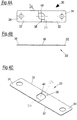
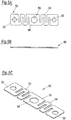
- eine Draufsicht, eine Seitenansicht und eine perspektivische Ansicht eines erfindungsgemäßen Federelements,
- Fig. 6
- eine Draufsicht auf ein dreiarmiges Montageelement,
- Fig. 7
- eine Draufsicht auf ein vierarmiges Montageelement,
- Fig. 8A-C
- eine perspektivische Darstellung einer erfindungsgemäßen Klemmeinrichtung, die mit der erfindungsgemäßen Montageeinrichtung gemäß den vorherigen Figuren verwendet werden kann, eine in Längsrichtung geschnittene Darstellung der Klemmeinrichtung der
Fig. 8B und eine vergrößerte Darstellung des umkreisten Bereichs der Darstellung gemäßFig. 8B , - Fig. 9A-F
- das erste Bauteil der erfindungsgemäßen Klemmeinrichtung der
Fig. 8A bis C in einer Ansicht von oben, in einer Längsebene geschnittene Ansicht, in einer Seitenansicht, in einer vergrößerten perspektivischen Ansicht eines mit Längsrippen versehenen Innenbereichs, in einer perspektivischer Ansicht von unten und in einer perspektivischer Ansicht von oben, - Fig. 10A-F
- das zweite Bauteil der erfindungsgemäßen Klemmeinrichtung der
Fig. 8A bis C in einer Ansicht von oben, in einer Längsebene geschnittene Ansicht, in einer Seitenansicht, in einer vergrößerten perspektivischen Ansicht eines mit Längsrippen versehenen Innenbereichs, in einer perspektivischer Ansicht von unten und in einer perspektivischer Ansicht von oben, - Fig. 11
- eine perspektivische Darstellung ähnlich der
Fig. 8A , bei der aber das erste Bauteil mit einer seitlichen Fahne versehen ist, die die eine erste Klemmfläche bildet, und die Kontermutter über eine getrennte Scheibe mit seitlicher Fahne wirkt, die eine zweite Klemmfläche bildet, und - Fig. 12
- eine Darstellung ähnlich der 9C jedoch mit einer alternativen Ausbildung des ersten Bauteils mit Sechskantaufnahme für ein Werkzeug.
- In den
Fig. 1A und 1B sind drei Montageeinrichtungen 10 gezeigt, die eine einstellbare und feststellbare winkelmäßige Anpassung eines Gegenstandes 12, hier in Form eines Projektors für ein Head-up-Display, an einen Träger 14 zulässt. Im konkreten Ausführungsbeispiel sind vier Montageeinrichtungen 10 vorhanden, von denen zwei auf der Vorderseite und zwei auf der Rückseite des quaderförmigen Projektors 2 benachbart zu dessen vertikalen Kanten 16 angeordnet sind, wobei die eine Montageeirichtung an der Rückseite in der Darstellung nicht ersichtlich ist. Konkret ist jede Montageeinrichtung an ihren Enden mittels Schraubbolzen 18 (Fig. 3A bis 3E ) an entsprechenden Halterungen 20 des Projektors befestigt. Der Träger 14 ist hier nur durch Kreise angedeutet, wird aber in diesem konkreten Beispiel üblicherweise durch eine Blechstruktur eines Kraftwagenarmaturenbretts gebildet, von dem ein Ausschnitt in schematischer Form detaillierter inFig. 2A gezeigt ist. Allerdings kommen im Beispiel derFig. 2A nur drei Montagepunkte für den Projektor 12 zum Einsatz, hier in der konkreten Form von länglichen Stanz-und Nietbolzen 22, die am Blechteil angenietet sind. Es können zum Beispiel SBF-Stanz- und Nietbolzen der Anmelderin zum Einsatz kommen, die mit ihrem Kopfteil 24 am Blech vernietet sind. Die nach oben weisende Gewinde aufweisende Schaftteile 22 der Stanz-und Nietbolzen gehen jeweils durch eine Klemmeinrichtung 28 in der Mitte jeder Montageeinrichtung, wie in denFig. 1A und 1B gezeigt. - Die
Fig. 2B zeigt, dass die Schaftteile 22 der Stanz- und Nietbolzen, die nachfolgend nur Gewindestifte genannt werden, Fehlorientierungen und Positionsfehler aufweisen können, die es zu kompensieren gilt, was mittels der erfindungsgemäßen Montageeinrichtungen 10 möglich ist, wie später näher erläutert wird. - Aus der
Fig. 2B ist ersichtlich, dass die Gewindestifte 22A und 22B winkelmäßige Abweichungen von der Sollposition, die durch eine gestrichelte Linie gezeigt ist, aufweisen und der dritte Gewindestift 22C seitlich versetzt von der Sollposition ist. - Die konkrete Konstruktion einer Montageeinrichtung 10 wird nunmehr genauer anhand der weiteren
Figuren 3A bis 3E ,4A bis 4E und 5A bis 5C erklärt. - Die Montageeinrichtung 10 umfasst mindestens ein geteiltes Montageelement 30 gemäß
Fig. 4A bis C , dessen zwei getrennte Teile 32 jeweils in einem Endbereich 34 einen Abschnitt aufweisen, der eine Befestigung an dem Gegenstand 12 direkt oder an einer jeweiligen am Gegenstand angebrachten Halterung 20 ermöglicht, und die an ihren, dem jeweiligen Abschnitt abgewandten, einander zugewandten und gegeneinander verschiebbaren, Enden 36 gemeinsam einen Klemmbereich 38 bilden, der eine Befestigung an dem Träger 14 ermöglicht. - Das hier gezeigte zweiteilige Montageelement 30 kann als zweiarmig bezeichnet werden. Es sind allerdings auch drei- oder viergeteilte Ausführungen denkbar, die dann als drei- oder vierarmig bezeichnet werden. Beispiele für solche drei- oder vierarmige Montageelemente sind in den
Fig. 6 und 7 gezeigt und die hier gegebene Beschreibung gilt auch sinngemäß für die Ausführungsformen nach denFig. 6 und 7 , in denen die entsprechenden Bezugszeichen soweit sinnvoll eingetragen sind. - Wie in den
Fig. 3A bis 3C gezeigt, kommen normalerweise mehrere geteilte, gleichartig ausgebildete Montageelemente 30 in einer Montageeinrichtung 10 zur Anwendung. Sie sind übereinander gelegt ausgerichtet und bilden ein Montagepaket 40. - Die Teile 32 des oder jedes Montageelements 30 sind gleich ausgebildet und werden als Blechstanzteile oder als Kunststoffteil ggf. mit Faserverstärkung ausgebildet.
- Die Abschnitte an den Enden 34 der Teile 32, die der Befestigung am Gegenstand bzw. an Halterungen des Gegenstands dienen, haben üblicherweise Ausschnitte, die beispielsweise als Befestigungslöcher ausgebildet sind. Sie werden mittels Befestigungsbolzen 35 an den Halterungen 20 angebracht.
- Die einander zugewandten Enden 36 der Teile 32 sind gegeneinander verschiebbar. In der ausgerichteten Stellung nach den
Fig. 3A bis 3C können sie sich berühren, oder einen kleinen Abstand voneinander aufweisen. Bei Verformung der Montageelemente, wie inFig. 3D oder 3E gezeigt, bewegen sie sich etwas auseinander. Die Teile können sich auch an ihren Enden 36 gegenseitig überlappen. In dem Fall wird der Grad der Überlappung bei Verformung des Montagelements verkleinert. In den gezeigten Beispielen weisen die einander zugewandten Enden 36 der Teile 32, die den Klemmbereich 38 bilden, jeweilige Ausschnitte 42 auf, die gemeinsam eine Öffnung 44 zur Aufnahme einer Klemmeinrichtung wie 28 (Fig. 1B ) bilden. - Wie in den
Fig.3A bis 3C gezeigt, bildet jedes der Teile 32 eines Montageelements 30 im Bereich des Ausschnittes 42 eine Zunge 46, die seitlich an dem Befestigungselement vorbeigeht. Bei der gezeigten Zweiteilung des Montageelements 10 sind die identisch ausgebildeten Teile 32 zueinander umgekehrt gelegt, so dass deren Zungen 46 die Klemmeinrichtung auf beiden Seiten einfassen. Beim Vorsehen von mehreren Montageelementen werden diese jeweils um 180 Grad um Ihre Längsachse 48 gedreht aufeinander gelegt, was der Stabilität der Montageeinrichtung zugutekommt. - Es ist bevorzugt, wenn mindestens auf der einen Seite des Montageelements 10, oder des Montagepakets 40, ein Federelement 50 gelegt ist, das den Befestigungsabschnitt an den Enden 34 mit einem flächigen Bereich 52 mindestens teilweise abdeckt und dazwischen mindestens einen in der Ebene des Montagelements federnden Bereich 54, hier zwei federnde Bereiche 54, aufweist. Der oder jeder Federbereich weist eine Schlangen- oder Mäanderform auf. Ferner hat das Federelement 50 vorzugsweise einen mittleren Bereich 56, der den Klemmbereich 38 mindestens teilweise überlappt und eine Öffnung 58 aufweist, die der Öffnung 44 entspricht.
- In den gezeigten Beispielen ist das Federelement 50 zweimal vorgesehen, wobei die Federelemente einmal oberhalb des Montagepakets 40 und einmal unterhalb des Montagepakets 40 angeordnet sind. Auch das Federelement oder jedes Federelement kann als Blechstanzteil oder als Kunststoffteil ggf. mit Faserverstärkung ausgebildet werden.
- Wie bereits angedeutet, weist jede Montageeinrichtung auch eine Klemmeinrichtung 28 auf, die am Klemmbereich klemmend wirkt und mittels eines Gewindestifts 22 am Träger 14 höhen- bzw. abstandsverstellbar anbringbar ist.
- Konkret weist die Klemmeinrichtung 28 gemäß den
Fig. 8A bis C folgende Bauteile auf: - Ein erstes, ein Innengewinde 60 aufweisendes, Bauteil 62 mit einer Seite 64, die entweder direkt oder indirekt über ein getrenntes Teil eine erste Klemmfläche 66 bildet.
- Ein zweites, ein Innengewinde 68 und ein Außengewinde 70 aufweisendes, Bauteil 72, das axialverschiebbar aber drehfest am ersten Bauteil 62 angebracht ist, wobei die jeweiligen Innengewinde 60, 68 des ersten Bauteils 62 und des zweiten Bauteils 72 ausgelegt sind, um mittels eines Bolzenelements 22 mit Außengewinde axialverstellbar gemeinsam an dem Träger 14 befestigt zu werden,
- Eine Kontermutter 74, die auf das Außengewinde 70 des zweiten Bauteils 72 aufgeschraubt ist, dessen, der erst genannten Klemmfläche 66 zugewandten, Seite 76 eine zweite Klemmfläche 78 bildet.
- Die erste und zweite einander zugewandten Klemmflächen 66, 78 sind zur klemmenden Aufnahme des Klemmbereichs 38 der Montageeinrichtung 10 ausgelegt.
- Die Klemmeinrichtung 28 kann auch für ganz andere Klemmzwecke verwendet werden, in diesem Fall wird der zu klemmende Gegenstand zwischen den Klemmflächen 66, 74 angeordnet.
- Das erste Bauteil 62 ist unter Beibehaltung der relativen axialen Verschiebbarkeit mittels einer insbesondere leicht lösbaren Verbindung 80 an dem zweiten Bauteil 72, in dieser Ausführung durch eine Klickverbindung befestigt, dessen Details am besten aus den einzelnen Zeichnungen der
Fig. 9A bis F und 10A bis F hervorgehen. - Das obere Ende des ersten Bauteils ist als Hohlzylinder 82 mit Längsrippen 84 an der inneren Fläche des Hohlzylinders ausgebildet, wobei ein Ringbereich 86 oberhalb der Rippen leicht nach Innen geneigt ist (am besten bei 86 aus der
Fig. 8C ersichtlich). Das untere Ende 88 des zweiten Bauteils 72 ist im Durchmesser gegenüber dessen Außengewinde 70 verkleinert und weist innere Längsnuten 90 auf, in die die Längsrippen 84 des ersten Bauteils gleitend aufgenommen sind, wodurch die gegenseitige axiale Verschiebbarkeit bei einer drehfesten Anordnung der beiden Bauteile 62, 72 sichergestellt ist. Dabei greift der radial nach Innen gerichtete Ringbereich 86 am freien Ende des Hohlzylinders 82 in eine Ringnut 92 hinter den Längsnuten 90 des zweiten Bauteils 72. Der Zylinderbereich 94 am unteren Ende des zweiten Bauteils greift somit in den Hohlzylinder 82 des ersten Bauteils 62. Die zwei Bauteile 62 und 72 sind somit aneinander befestigt aber immer noch gegeneinander axial verschiebbar, wobei das Ausmaß der axialen Verschiebbarkeit nicht mehr als die axiale Länge eines Gewindegangs betragen muss, was durch die Breite der Ringnut 92 bestimmt werden kann. - Anstelle einer Klickverbindung kann eine permanente Verbindung unter Beibehaltung der relativen axialen Verschiebbarkeit erreicht werden, wenn zum Beispiel der Ringbereich 86 wie ein Nietbördel noch tiefer in die Ringnut 92 hineingepresst wird.
- Das zweite Bauteil 72 weist insbesondere im Bereich seines, dem ersten Bauteil 62 abgewandten, oberen Endes 96 eine Werkzeugaufnahme 98 zur lösbaren Anbringung eines Drehwerkzeugs auf. Die Werkzeugaufnahme 98 des zweiten Bauteils ist in seinen Querabmessungen kleiner ausgebildet als die Kontermutter 74, damit das zweite Bauteil 72 und die Kontermutter 74 mit unterschiedlichen koaxial angeordneten Drehwerkzeugen gemeinsam oder relativ zueinander drehbar sind.
- Die Werkzeugaufnahme 98 des zweiten Bauteils ist am einfachsten durch eine Innenaufnahme 100 nach Art einer Imbusschraube oder einer Torxaufnahme gebildet, die vorzugsweise in dem, dem ersten Bauteil abgewandten Stirnende des zweiten Bauteils vorgesehen ist.
- Das erste Bauteil kann ebenfalls mit einer Werkzeugaufnahme 102 versehen werden, die insbesondere in Form einer Außenmehrkant, wie ein Außensechskant, ausgebildet sein kann, wie in der
Fig. 12 gezeigt ist. Diese Werkzeugaufnahme 102 kann von Vorteil sein, zum Beispiel dann, wenn die Klemmeinrichtung 28 von Hand betätigt wird. Sollte eine Werkzeugaufnahme wie 102 am ersten Bauteil 62 vorgesehen werden, könnte auf eine Werkzeugaufnahme wie 98 am zweiten Bauteil 72 verzichtet werden. - In dem Beispiel gemäß
Fig. 8A bis C ist das erste Bauteil mit einem integrierten Flansch 104 versehen ist, dessen, dem zweiten Bauteil zugewandten, Stirnseite direkt die erste Klemmfläche bildet. In der gleichen Weise ist die Kontermutter 74 mit einem integrierten Flansch 106 versehen, dessen, dem ersten Bauteil 62 zugewandten, Stirnseite direkt die zweite Klemmfläche 78 bildet. Alternativ hierzu könnte die Kontermutter 74, wie inFig. 11 gezeigt an eine separate Scheibe 112 angreifen, die die zweite Klemmfläche 78 bildet. - Man sieht aus den
Fig. 3A bis C , dass sich ein Bereich des Außengewindes 70 des zweiten Bauteils 72 und der Bereich des Übergangs vom ersten Bauteil 62 in den zweiten Bauteil 72 durch die Öffnung 44 der Montageeinrichtung 10 hindurch erstreckt. Mit anderen Worten erstreckt sich das Außengewinde 70 des zweiten Bauteils durch den Ausschnitt im Klemmbereich 38 der Montageeinrichtung 10, wobei die Montageeinrichtung zwischen dem ersten Bauteil 62 und der auf dem zweiten Bauteil 72 aufgeschraubten Kontermutter 74 klemmbar ist. - Die gegenseitige axiale Verschiebbarkeit des ersten Bauteils 62 und des zweiten Bauteils 72 stellt sicher, dass das Gewinde des Stehbolzens 22 beide Bauteile ohne weiteres durchdringen kann, da der Längenausgleich trotz der drehfesten Anordnung eine durchgehende Gewindefurche sicherstellt. Die Drehbarkeit der Klemmeinrichtung als Einheit auf dem Stehbolzen 22 ermöglicht eine genaue Positionierung der Höhe der einen Klemmfläche 66 gegenüber dem Träger 14. Durch Drehen der Kontermutter kann dann die andere Klemmfläche 78 in Richtung auf die erstgenannte Klemmfläche 66 zu bewegt werden, und die Montageeinrichtung 10 zwischen den Klemmflächen 66 und 78 geklemmt werden, ohne die vorher eingestellte Position der erstgenannten Klemmfläche 66, die den Höhenausgleich sicherstellt, zu stören. Da die Montageeinheit 10 im nicht geklemmten Zustand flexibel ist, kann sie die S-Form gemäß
Fig. 3D passend zu der Fehlorientierung des Stehbolzens 22 oder desgleichen automatisch und leicht annehmen, wie auch eine etwaige in einer Querebene gekippte Position des Klemmbereichs gemäßFig. 3E , der vollflächig an der erstgenannten Klemmfläche 66 anliegt. Dabei wird die von der Kontermutter 74 gebildete Klemmfläche 78 parallel zur erstgenannten Klemmfläche 66 geführt, so dass auch diese Klemmfläche 78 vollflächig zur Anlage an den Klemmbereich kommt. Beim Festziehen der Kontermutter 74 wird das zweite Bauteil 72 aufgrund der beschränkten axialen Verschiebbarkeit zwischen dem ersten Bauteil 62 und dem zweiten Bauteil 72 zunächst minimal etwas von dem ersten Bauteil 62 entfernt, wodurch die Kontermutter 74 nun ihre konternde Funktion entfaltet und den Klemmbereich zwischen den beiden Klemmflächen 66, 78 festklemmt. Hierdurch wird die Montageeinrichtung automatisch in der ausgewählten ausgerichteten Position "eingefroren". Die Montageeinrichtung ist nun von einem flexiblen Gebilde in ein eher steifes Gebilde umgewandelt worden, wenn auch eine gewisse dämpfende Wirkung noch gegeben ist. - Wie in
Fig. 12 gezeigt ist, kann der Klemmbereich der Klemmeinrichtung seitlich von der mittleren Längsachse verlagert werden. Hierzu wird das erste Bauteil entweder mit einer seitlich angeordneten Fahne 108 versehen, deren, dem zweiten Bauteil 72 zugewandten, Seite 110 direkt die erste Klemmfläche 66 bildet. Die Kontermutter 74 drückt dann an eine getrennte Scheibe 112, die ebenfalls mit einer seitlich angeordneter Fahne 114 versehen ist, deren, dem ersten Bauteil 62 zugewandten, Seite 116 die zweite Klemmfläche 78 bildet. Die zweite Klemmfläche 78 und die erste Klemmfläche 66 formen gemeinsam eine U-förmige Klemmaufnahme 118.
Zwischen der seitlich angeordneten ersten Klemmfläche 66 der Klemmeinrichtung 28 und der seitlich angeordneten zweiten Klemmfläche 78 der Klemmeinrichtung 28 wird eine U-förmige Klemmaufnahme gebildet, die wie bei einem Schraubenstock einen Gegenstand, hier den Klemmbereich der Montageeinrichtung 10, klemmend aufnehmen kann. - Die Bauteile der Klemmeinrichtung sind vorzugsweise alle aus Metall ausgebildet, könnten aber alternativ hierzu einzeln, oder alle, aus faserverstärktem Kunststoff bestehen. Wenn sie aus Metall bestehen, dann werden sie vernünftigerweise wie Befestigungselemente im Allgemeinen als Kaltschlagteile angefertigt.
- Der Zusammenbau der kompletten Montageeinrichtung kann auf verschiedener Weise erfolgen.
- Es ist zum Beispiel möglich, der Montagepaket 40, oder nur die zwei Teile eines einzigen Montageelements 30, mit oder ohne eines Federelements 40 oder beider Federelemente 50, falls ein solches überhaupt vorhanden ist, an die Halterungen 20 des Gegenstandes mittels Befestigungsschrauben 35 anzuschrauben, die durch die Befestigungslöcher eingeführt werden, die die Ausschnitte an den Enden 34 der Teile 32 jedes Montageelements bilden. Wenn ein Federelement 50 vorgesehen ist, werden die Befestigungsbolzen 35 auch durch die entsprechenden Löcher an den Enden des Federelements geführt. Wird nur ein Federelement 50 verwendet, wird dies üblicherweise unterhalb der Köpfe der Befestigungsbolzen 35 gelegt. Wenn zwei Federelemente vorgesehen sind, ist es egal welches oben und welches unten liegt.
- Als nächstes wird die Klemmeinrichtung 28 montiert. Dies kann dadurch erfolgen, dass das erste Bauteil 62 von unten kommend mit dem unteren Ende des von oben kommenden zweiten Bauteils 72, das durch die Öffnung 44 hindurchgeführt wird, mittels der beschriebenen Klickverbindung zusammengefügt werden. Die Kontermutter 74 kann vorher auf das zweite Bauteil aufgeschraubt werden, oder erst jetzt, ist aber noch nicht festgezogen worden. Der Gegenstand mit den montierten Montageeinrichtungen wird dann auf dem Träger positioniert, so dass jede Schraubbolzen 22 mit der dazu zugeordneten Montageeinrichtung 10 ausgerichtet ist. Dies kann manuell oder automatisch erfolgen. Eine Hilfe bietet hier ein ausgeprägter Einführkonus am unteren Ende jedes erste Bauteil 62. Da die Kontermutter 74 noch nicht festgezogen sind, (ist bei nur eine Montageeinrichtung 10) sind die Montageelemente 30 bzw. die Montagepakete 40 noch flexibel und passen sich automatisch die aktuelle Winkelposition der Schraubbolzen 22 an. Durch Drehen der aus dem ersten Bauteil 62 und dem zweiten Bauteil 72 bestehenden Einheit wird diese Einheit entlang des jeweiligen Schraubbolzens 22 bewegt, bis die erwünschte Position erreicht ist. Die Klemmfläche 66 bestimmt dann die Position des Gegenstandes 12. Die axiale Verschiebbarkeit zwischen dem ersten Bauteil 62 und dem zweiten Bauteil 72 stellt sicher, dass das Gewinde des Schraubbolzens 22 hindurchgeführt werden kann obwohl diese drehfest aneinander befestigt sind. Sonst wäre dies nicht möglich, da der genaue Anfang der beiden Innengewinde 60 und 68 in Bezug auf die mittlere Längsachse des ersten Bauteils 62 und des zweiten Bauteils 72 wenigstens bei den üblichen Herstellungsmethoden nicht vorhersehbar ist und daher kompensiert werden muss.
- Wenn die erwünschte Position erreicht ist, wird die Kontermutter 74 festgezogen damit die zweite Klemmfläche 78 in Eingriff mit dem Klemmbereich 38 der Montageeinrichtung 10 kommt und der leicht verformte Zustand des jeweiligen Montageelements 30 bzw. des jeweiligen Montagepakets 40 eingefroren wird. Die Montage ist erfolgt.
- Denkbar ist auch das Montageelement 30, oder das Montagepaket 40, ggf. mit einem Federelement 50 oder mit zwei Federelementen 50 mit der Klemmeinrichtung vor der Montage an den Gegenstand 12 oder an dessen Halterungen zusammenzubauen. Die Kontermutter 74 kann dann angezogen werden um die Montageeinrichtung zusammenzuhalten. In diesem Fall wird die Kontermutter 74 dann wieder gelockert werden müssen vor der Anbringung der Klemmeinrichtung an die Schraubbolzen 22. Alternativ hierzu könnten die Befestigungsbolzen 35, die zur Befestigung der Montageeinrichtung 10 an dem Gegenstand 12 bzw. an den Halterungen 20 dienen, vorher an die Montageeinrichtung 10 montiert werden, um den Zusammenhalt der Teile zu gewährleisten. Zum Beispiel könnten die Befestigungsbolzen 35 als Gewindeführende- oder Schneidende-Bolzen ausgeführt werden, die nur in der unterste Lage des jeweiligen Montagepakets 40 (je nach Auslegung ein Montageelement 30 oder ein Federelement 50) ein Gewinde formt oder schneidet. Bei der endgültigen Anbringung am Gegenstand 12, oder an den Halterungen 20, werden beim Weiterdrehen der Befestigungsbolzen 43, die in der untersten Lage geformten Gewinde zerstört, haben aber bereits ihr Zweck des provisorischen Zusammenhalts erfüllt.
- Auch könnten andere Hilfsmittel dem Zweck des provisorischen Zusammenhalts Erfüllen, zum Beispiel könnte Schrumpfschlauch verwendet werden um die Montageeinheit zusammenzuhalten.
- Die vorherige Montage der Befestigungsbolzen 35 hat auch Vorteile bei der Automatische Montage. Besonders günstig wäre es wenn die Befestigungsbolzen 35 von oben kommend an den Gegenstand 12 bzw. an den Halterungen 20 angebracht werden. Dann könnte die gesamte Montage einer Montageeinheit 10 mit einer automatisierten Einrichtung mit entsprechenden Drehwerkzeugen von oben kommend erfolgen.
- In manchen Einbausituationen können das erste Bauteil und das zweite Bauteil mit Vorteil vertauscht werden, beispielsweise so, dass das erste Bauteil 62 oben und das zweite Bauteil 72 unten angeordnet ist.
-
- 10
- Montageeinrichtung
- 12
- Projektor, Gegenstand
- 14
- Träger
- 16
- vertikale Kanten vom Gegenstand 12
- 20
- Halterung
- 22
- Stanz- und Nietbolzen, Befestigungselement
- 24
- Kopfteil des Stanz- und Nietbolzens 22
- 26
- Schaftteil des Stanz- und Nietbolzens, Gewindestift
- 28
- Klemmeinrichtung
- 30
- Montageelement
- 32
- Teil des Montageelements 30
- 34
- Endbereich von Teil 32, Abschnitt
- 35
- Befestigungsbolzen
- 36
- anderes Ende von Teil 32
- 38
- Klemmbereich von Montageelement 30
- 40
- Montagepaket
- 42
- Ausschnitt an den Enden 36 der Teile 32, Befestigungsloch
- 44
- Öffnung
- 46
- Zunge
- 48
- Längsrichtung von Montageelement 30
- 50
- Federelement
- 52
- flächiger Bereich vom Federelement 50
- 54
- federnder Bereich vom Federelement 50
- 56
- mittlerer Bereich vom Federelement 50
- 58
- Öffnung vom Federelement 50
- 60
- Innengewinde vom ersten Bauteil 62
- 62
- erstes Bauteil
- 64
- Seite von ersten Bauteil 62
- 66
- Klemmfläche
- 68
- Innengewinde vom zweiten Bauteil 72
- 70
- Außengewinde vom zweiten Bauteil 72
- 72
- zweites Bauteil
- 74
- Kontermutter
- 76
- Seite von der Kontermutter
- 78
- zweite Klemmfläche
- 80
- Verbindung zwischen dem ersten Bauteil 62 und dem zweiten Bauteil 72
- 82
- Hohlzylinder am oberen Ende vom ersten Bauteil 62
- 84
- Längsrippen
- 86
- Ringbereich am Ende des Hohlzylinders 82
- 88
- unteres Ende des zweiten Bauteils 72
- 90
- innere Längsnuten am zylindrischen Ende vom zweiten Bauteil 72
- 92
- Ringnut
- 94
- Zylinderbereich am unteren Ende des zweiten Bauteils 72
- 96
- oberes Ende vom zweiten Bauteil 72
- 98
- Werkzeugaufnahme
- 100
- Innenaufnahme
- 102
- Werkzeugaufnahme am ersten Bauteil 62
- 104
- Flansch vom ersten Bauteil 62
- 106
- Flansch von der Kontermutter 74
- 108
- Fahne von Flansch des ersten Bauteils 62
- 110
- Seite von Fahne 108
- 112
- separate Scheibe
- 114
- Fahne von der Scheibe 112
- 116
- Seite der separaten Scheibe 112
- 118
- Klemmaufnahme
Claims (14)
- Klemmeinrichtung (28), insbesondere zur Anwendung mit einer Montageeinrichtung (10), gekennzeichnet durch ein ein Innengewinde (60) aufweisendes erstes Bauteil (62) mit einer Seite (64), die entweder direkt oder indirekt über ein getrenntes Teil eine erste Klemmfläche (66) bildet, durch ein zweites ein Innengewinde (68) und ein Außengewinde (70) aufweisendes Bauteil (72), das axial verschiebbar aber drehfest am ersten Bauteil (62) anbringbar ist, wobei die jeweiligen Innengewinde (60) des ersten Bauteils (62) und des zweiten Bauteils (72) ausgelegt sind, um mittels eines Bolzenelements mit Außengewinde (26) höhen- bzw. abstandsverstellbar gemeinsam an einem Träger (14) befestigt zu werden und durch eine Kontermutter (74), die auf das Außengewinde (70) des zweiten Bauteils (72) aufschraubbar ist, dessen der erstgenannten Klemmfläche (66) zugewandte Seite entweder direkt oder indirekt über ein zweites Teil (112) eine zweite Klemmfläche (78) bildet, wobei die erste und zweite einander zugewandte Klemmfläche (66, 78) zur klemmenden Aufnahme eines Gegenstandes (12) bzw. des Klemmbereichs (38) der Montageeinrichtung (10) ausgelegt sind.
- Klemmeinrichtung (28) nach Anspruch 1,
dadurch gekennzeichnet, dass das erste Bauteil (62) am zweiten Bauteil (72) mittels einer insbesondere leicht lösbaren Verbindung (80), wie zum Beispiel einer Klickverbindung, oder durch eine eher permanente Verbindung wie einen umgebördelten Kragen (Ringbereich 86) an dem einen Bauteil, der in einer Hinterschneidung (von der Ringnut (92) gebildet) eingreift, unter Beibehaltung der relativen axialen Verschiebbarkeit befestigt ist. - Klemmeinrichtung (28) nach Anspruch 1 oder 2,
dadurch gekennzeichnet, dass das zweite Bauteil (72) insbesondere im Bereich seines dem ersten Bauteil abgewandten Endes (96) eine Werkzeugaufnahme (98) zur lösbaren Anbringung eines Drehwerkzeugs aufweist, wobei die Werkzeugaufnahme (98) des zweiten Bauteils (72) vorzugsweise in seiner Querabmessung kleiner ausgebildet ist als die Kontermutter (74), damit das zweite Bauteil (72) und die Kontermutter (74) mit unterschiedlichen koaxial angeordneten Drehwerkzeugen gemeinsam oder relativ zueinander drehbar sind. - Klemmeinrichtung (28) nach Anspruch 3,
dadurch gekennzeichnet, dass die Werkzeugaufnahme (98) des zweiten Bauteils durch eine Innenaufnahme (100) gebildet ist, die vorzugsweise in das dem ersten Bauteil abgewandte Stirnende des zweiten Bauteils vorgesehen ist. - Klemmeinrichtung (28) nach einem der vorhergehenden Ansprüche,
dadurch gekennzeichnet, dass das erste Bauteil mit einer Werkzeugaufnahme (102) versehen ist, insbesondere in Form eines Außenmehrkants. - Klemmeinrichtung (28) nach einem der vorhergehenden Ansprüche,
dadurch gekennzeichnet, dass das erste Bauteil (62) mit einem Flansch (104) versehen ist, dessen dem zweiten Bauteil (72) zugewandte Stirnseite direkt die erste Klemmfläche (66) bildet oder an eine Scheibe angreift, die die erste Klemmfläche bildet. - Klemmeinrichtung (28) nach einem der vorhergehenden Ansprüche 1 bis 5, dadurch gekennzeichnet, dass die Kontermutter (74) mit einem Flansch (106) versehen ist, dessen dem ersten Bauteil (62) zugewandte Stirnseite direkt die zweite Klemmfläche (78) bildet oder an eine Scheibe (112) angreift, die die zweite Klemmfläche bildet.
- Klemmeinrichtung (28) nach einem der vorhergehenden Ansprüche,
dadurch gekennzeichnet, dass das Außengewinde (70) des zweiten Bauteils (72) sich durch einen Ausschnitt (44) im Klemmbereich (38) der Montageeinrichtung (10) erstreckt, wobei die Montageeinrichtung (10) zwischen dem ersten Bauteil (62) und der auf dem zweiten Bauteil aufgeschraubten Kontermutter (74) klemmbar ist. - Klemmeinrichtung (28) nach einem der Ansprüche 1 bis 5,
dadurch gekennzeichnet, dass das erste Bauteil (62) entweder mit einer seitlich angeordneten Fahne (108) versehen ist, deren dem zweiten Bauteil (72) zugewandte Seite direkt die erste Klemmfläche (66) bildet oder an eine vorzugsweise drehfest am ersten Bauteil (62) befestigte Scheibe angreift, die mit einer seitlich angeordneten Fahne versehen ist, deren dem zweiten Bauteil zugewandte Seite die erste Klemmfläche bildet. - Klemmeinrichtung (28) nach einem der vorhergehenden Ansprüche 1 bis 5, dadurch gekennzeichnet, dass die Kontermutter (74) entweder mit einer seitlich angeordneten Fahne versehen ist, deren dem ersten Bauteil (62) zugewandte Seite direkt die zweite Klemmfläche bildet oder an eine vorzugsweise drehfest aber axial verschiebbar am ersten Bauteil (62) befestigte Scheibe (112) angreift, die mit einer seitlich angeordneten Fahne (114) versehen ist, deren dem ersten Bauteil (62) zugewandte Seite die zweite Klemmfläche (78) bildet.
- Klemmeinrichtung (28) nach einem der vorhergehenden Ansprüche, 9 oder 10,
dadurch gekennzeichnet, dass zwischen der seitlich angeordneten ersten Klemmfläche (66) der Klemmeinrichtung und der seitlich angeordneten zweiten Klemmfläche (78) der Klemmeinrichtung, eine Klemmaufnahme (118) gebildet ist, in der beispielsweise der Klemmbereich (38) der Montageeinrichtung (10) oder ein eines anderen zu klemmenden Teils wie der Spiegel eines Interferometers klemmbar ist. - Klemmeinrichtung (28) nach einem der vorhergehenden Ansprüche,
dadurch gekennzeichnet, dass das erste Bauteil (62), das zweite Bauteil (72) und die Kontermutter alle aus Metall bestehen oder einige davon aus Metall und andere aus Kunststoff ggf. mit Faserverstärkung bestehen. - Klemmeinrichtung (28) nach Anspruch 12,
dadurch gekennzeichnet, dass die aus Metall bestehenden Teile als Kaltschlagteile angefertigt sind. - Klemmeinrichtung (28) nach einem der vorhergehenden Ansprüche 1 bis 11,
dadurch gekennzeichnet, dass das erste Bauteil (62), das zweite Bauteil (72) und die Kontermutter alle aus Kunststoff ggf. mit Faserverstärkung bestehen, wobei sie vorzugsweise im Spritzgußverfahren hergestellt sind.
Applications Claiming Priority (1)
| Application Number | Priority Date | Filing Date | Title |
|---|---|---|---|
| DE102017111665.6A DE102017111665A1 (de) | 2017-05-29 | 2017-05-29 | Klemmeinrichtung |
Publications (2)
| Publication Number | Publication Date |
|---|---|
| EP3409957A1 true EP3409957A1 (de) | 2018-12-05 |
| EP3409957B1 EP3409957B1 (de) | 2020-02-19 |
Family
ID=62245182
Family Applications (1)
| Application Number | Title | Priority Date | Filing Date |
|---|---|---|---|
| EP18173772.7A Active EP3409957B1 (de) | 2017-05-29 | 2018-05-23 | Klemmeinrichtung |
Country Status (6)
| Country | Link |
|---|---|
| US (1) | US20180340558A1 (de) |
| EP (1) | EP3409957B1 (de) |
| CN (1) | CN108930694A (de) |
| DE (1) | DE102017111665A1 (de) |
| ES (1) | ES2777476T3 (de) |
| MX (1) | MX2018006440A (de) |
Cited By (1)
| Publication number | Priority date | Publication date | Assignee | Title |
|---|---|---|---|---|
| EP3741485A1 (de) * | 2019-05-20 | 2020-11-25 | Andreas Stihl AG & Co. KG | Arbeitsgerät und stehbolzen für ein arbeitsgerät |
Families Citing this family (3)
| Publication number | Priority date | Publication date | Assignee | Title |
|---|---|---|---|---|
| USD837017S1 (en) * | 2016-02-26 | 2019-01-01 | Advanced Machine & Engineering Co. | Centering dovetail vise |
| TR2022010690A2 (tr) * | 2022-06-28 | 2022-07-21 | Uentes Isitma Klima Sogutma Sanayi Ve Ticaret A S | Bi̇r taşima mapasi |
| KR20250146735A (ko) * | 2024-04-02 | 2025-10-13 | 현대모비스 주식회사 | 헤드업 디스플레이의 가결합 보조 장치 |
Citations (2)
| Publication number | Priority date | Publication date | Assignee | Title |
|---|---|---|---|---|
| US4402203A (en) * | 1982-07-22 | 1983-09-06 | Deutsch Fastener Corp. | Fastener installation tool |
| EP0228993A2 (de) * | 1985-12-16 | 1987-07-15 | HILTI Aktiengesellschaft | Vorrichtung zum Befestigen von Gegenständen an einem Untergrund |
Family Cites Families (17)
| Publication number | Priority date | Publication date | Assignee | Title |
|---|---|---|---|---|
| GB1093714A (en) * | 1964-06-05 | 1967-12-06 | Avdel Ltd | Improvements in or relating to blind hole anchor nut fastener devices |
| DE3812648A1 (de) | 1987-04-16 | 1988-11-03 | Yazaki Corp | Anzeigevorrichtung fuer ein fahrzeug |
| JP3575211B2 (ja) * | 1997-02-24 | 2004-10-13 | 三菱電機株式会社 | 付属装置 |
| JP4536247B2 (ja) * | 2000-11-22 | 2010-09-01 | 株式会社内田洋行 | クランプ装置 |
| DE102007055777A1 (de) * | 2007-12-12 | 2009-06-18 | Hilti Aktiengesellschaft | Handwerkzeugmaschine mit Spannmutter |
| US8230566B2 (en) | 2008-06-18 | 2012-07-31 | Kuritakoki Co., Ltd. | Sleeve puller |
| US8057145B2 (en) * | 2008-06-26 | 2011-11-15 | Jetyd Corp. | Radially expanding bolt assembly |
| FR2969232B1 (fr) * | 2010-12-21 | 2013-01-04 | Sagem Defense Securite | Organe d'attache d'un bati a une glissiere et bati equipe d'un tel organe d'attache |
| FR3006723B1 (fr) * | 2013-06-11 | 2015-12-04 | Snecma | Dispositif de fixation de deux pieces entre elles |
| WO2015077176A1 (en) * | 2013-11-22 | 2015-05-28 | Samtec, Inc. | Two-piece unmate-assist standoff |
| DE102015113676A1 (de) | 2015-08-18 | 2017-02-23 | Profil Verbindungstechnik Gmbh & Co. Kg | Blindnietelement |
| DE102016100933B4 (de) | 2016-01-20 | 2024-04-25 | Fairchild Fasteners Europe - Camloc Gmbh | Montagewerkzeug, dessen Verwendung und Verfahren zur Befestigung eines Gewindeeinsatzes |
| CN105805100B (zh) * | 2016-03-29 | 2019-04-23 | 西安中科微精光子制造科技有限公司 | 可调式锁紧装置 |
| CN205806118U (zh) * | 2016-07-14 | 2016-12-14 | 中国重汽集团济南动力有限公司 | 一种支架固定装置 |
| CN205853862U (zh) * | 2016-07-15 | 2017-01-04 | 中信国安盟固利动力科技有限公司 | 一种锂电池箱体固定装置 |
| CN205858920U (zh) * | 2016-07-29 | 2017-01-04 | 东风商用车有限公司 | 一种嵌入式六角法兰面螺母 |
| CN205858869U (zh) * | 2016-08-03 | 2017-01-04 | 大连宏海新能源发展有限公司 | 一种夹紧装置 |
-
2017
- 2017-05-29 DE DE102017111665.6A patent/DE102017111665A1/de not_active Withdrawn
-
2018
- 2018-05-23 ES ES18173772T patent/ES2777476T3/es active Active
- 2018-05-23 EP EP18173772.7A patent/EP3409957B1/de active Active
- 2018-05-24 MX MX2018006440A patent/MX2018006440A/es unknown
- 2018-05-29 CN CN201810530323.XA patent/CN108930694A/zh active Pending
- 2018-05-29 US US15/991,475 patent/US20180340558A1/en not_active Abandoned
Patent Citations (2)
| Publication number | Priority date | Publication date | Assignee | Title |
|---|---|---|---|---|
| US4402203A (en) * | 1982-07-22 | 1983-09-06 | Deutsch Fastener Corp. | Fastener installation tool |
| EP0228993A2 (de) * | 1985-12-16 | 1987-07-15 | HILTI Aktiengesellschaft | Vorrichtung zum Befestigen von Gegenständen an einem Untergrund |
Cited By (2)
| Publication number | Priority date | Publication date | Assignee | Title |
|---|---|---|---|---|
| EP3741485A1 (de) * | 2019-05-20 | 2020-11-25 | Andreas Stihl AG & Co. KG | Arbeitsgerät und stehbolzen für ein arbeitsgerät |
| US11867218B2 (en) | 2019-05-20 | 2024-01-09 | Andreas Stihl Ag & Co. Kg | Work apparatus and stud bolt for a work apparatus |
Also Published As
| Publication number | Publication date |
|---|---|
| DE102017111665A1 (de) | 2018-11-29 |
| MX2018006440A (es) | 2019-05-27 |
| EP3409957B1 (de) | 2020-02-19 |
| ES2777476T3 (es) | 2020-08-05 |
| US20180340558A1 (en) | 2018-11-29 |
| CN108930694A (zh) | 2018-12-04 |
Similar Documents
| Publication | Publication Date | Title |
|---|---|---|
| EP2720907B1 (de) | Befestigungselement mit toleranzausgleichsfunktion | |
| EP3036443B1 (de) | Verfahren zum verbinden von bauteilen sowie baugruppe | |
| EP3409957B1 (de) | Klemmeinrichtung | |
| DE102016100546A1 (de) | Blechmutter | |
| EP2435768A2 (de) | Vorrichtung zur befestigung einer montageschiene an einem gewindeschaft | |
| WO2009106261A1 (de) | Befestigungsanordnung mit selbsttätigem dreidimensionalem toleranzausgleich | |
| EP3209888A1 (de) | Schnellbefestiger, verfahren zur verbindung von zwei bauteilen mittels des schnellbefestigers und herstellungsverfahren dafür | |
| EP3707396B1 (de) | Verliersicherung für schrauben und montageeinheit | |
| EP1533185B1 (de) | Toleranzausgleichselement | |
| EP3336369A1 (de) | Befestigungssystem | |
| EP3121406B1 (de) | Auspuffrohr-montageanordnung | |
| EP0232917A2 (de) | Verfahren sowie Klemmverbindung und Halterung zur Montage von Bildschirmgeräten | |
| EP3889448A1 (de) | Befestigungselement | |
| EP1039155A2 (de) | Befestigungsanordnung für die Anbringung eines Bauteils an einer C-förmigen Halteschiene | |
| DE102005015033A1 (de) | Befestigungselement zur Anbringung auf einem Gewindebolzen | |
| EP3409956B1 (de) | Montageeinrichtung | |
| DE102014113126B4 (de) | Toleranzausgleichsvorrichtung | |
| EP3569880A1 (de) | Schwimmende, verliergesicherte anordnung eines verbindungselementes an einem bauteil | |
| DE202012008730U1 (de) | Befestigungseinrichtung | |
| EP3271594B1 (de) | Verbindungsanordnung zum ausgleich fertigungs- und/oder montagebedingter toleranzen zwischen bauteilen | |
| DE202013005582U1 (de) | System umfassend ein Trägerbauteil | |
| EP3420238A1 (de) | Vorrichtung zum ausgleichen von toleranzen | |
| DE19750252A1 (de) | Befestigungsvorrichtung | |
| EP1612432B1 (de) | Befestigungsanordnung für eine Verkleidung und Befestigungsverfahren | |
| DE10048279A1 (de) | Einrichtung zum reproduzierbaren Befestigen eines ersten Bauteiles an einem zweiten Bauteil |
Legal Events
| Date | Code | Title | Description |
|---|---|---|---|
| PUAI | Public reference made under article 153(3) epc to a published international application that has entered the european phase |
Free format text: ORIGINAL CODE: 0009012 |
|
| STAA | Information on the status of an ep patent application or granted ep patent |
Free format text: STATUS: THE APPLICATION HAS BEEN PUBLISHED |
|
| STAA | Information on the status of an ep patent application or granted ep patent |
Free format text: STATUS: REQUEST FOR EXAMINATION WAS MADE |
|
| AK | Designated contracting states |
Kind code of ref document: A1 Designated state(s): AL AT BE BG CH CY CZ DE DK EE ES FI FR GB GR HR HU IE IS IT LI LT LU LV MC MK MT NL NO PL PT RO RS SE SI SK SM TR |
|
| AX | Request for extension of the european patent |
Extension state: BA ME |
|
| 17P | Request for examination filed |
Effective date: 20181112 |
|
| RBV | Designated contracting states (corrected) |
Designated state(s): AL AT BE BG CH CY CZ DE DK EE ES FI FR GB GR HR HU IE IS IT LI LT LU LV MC MK MT NL NO PL PT RO RS SE SI SK SM TR |
|
| REG | Reference to a national code |
Ref country code: DE Ref legal event code: R079 Ref document number: 502018000786 Country of ref document: DE Free format text: PREVIOUS MAIN CLASS: F16B0005020000 Ipc: F16B0002060000 |
|
| GRAP | Despatch of communication of intention to grant a patent |
Free format text: ORIGINAL CODE: EPIDOSNIGR1 |
|
| STAA | Information on the status of an ep patent application or granted ep patent |
Free format text: STATUS: GRANT OF PATENT IS INTENDED |
|
| RIC1 | Information provided on ipc code assigned before grant |
Ipc: F16B 5/02 20060101ALI20190322BHEP Ipc: F16B 2/06 20060101AFI20190322BHEP Ipc: F16B 2/12 20060101ALI20190322BHEP Ipc: F16M 13/02 20060101ALI20190322BHEP |
|
| INTG | Intention to grant announced |
Effective date: 20190429 |
|
| GRAJ | Information related to disapproval of communication of intention to grant by the applicant or resumption of examination proceedings by the epo deleted |
Free format text: ORIGINAL CODE: EPIDOSDIGR1 |
|
| STAA | Information on the status of an ep patent application or granted ep patent |
Free format text: STATUS: REQUEST FOR EXAMINATION WAS MADE |
|
| GRAP | Despatch of communication of intention to grant a patent |
Free format text: ORIGINAL CODE: EPIDOSNIGR1 |
|
| STAA | Information on the status of an ep patent application or granted ep patent |
Free format text: STATUS: GRANT OF PATENT IS INTENDED |
|
| INTC | Intention to grant announced (deleted) | ||
| INTG | Intention to grant announced |
Effective date: 20190919 |
|
| GRAS | Grant fee paid |
Free format text: ORIGINAL CODE: EPIDOSNIGR3 |
|
| GRAA | (expected) grant |
Free format text: ORIGINAL CODE: 0009210 |
|
| STAA | Information on the status of an ep patent application or granted ep patent |
Free format text: STATUS: THE PATENT HAS BEEN GRANTED |
|
| AK | Designated contracting states |
Kind code of ref document: B1 Designated state(s): AL AT BE BG CH CY CZ DE DK EE ES FI FR GB GR HR HU IE IS IT LI LT LU LV MC MK MT NL NO PL PT RO RS SE SI SK SM TR |
|
| REG | Reference to a national code |
Ref country code: CH Ref legal event code: EP |
|
| REG | Reference to a national code |
Ref country code: DE Ref legal event code: R096 Ref document number: 502018000786 Country of ref document: DE |
|
| REG | Reference to a national code |
Ref country code: AT Ref legal event code: REF Ref document number: 1235291 Country of ref document: AT Kind code of ref document: T Effective date: 20200315 |
|
| REG | Reference to a national code |
Ref country code: IE Ref legal event code: FG4D Free format text: LANGUAGE OF EP DOCUMENT: GERMAN |
|
| REG | Reference to a national code |
Ref country code: NL Ref legal event code: MP Effective date: 20200219 |
|
| PG25 | Lapsed in a contracting state [announced via postgrant information from national office to epo] |
Ref country code: RS Free format text: LAPSE BECAUSE OF FAILURE TO SUBMIT A TRANSLATION OF THE DESCRIPTION OR TO PAY THE FEE WITHIN THE PRESCRIBED TIME-LIMIT Effective date: 20200219 Ref country code: FI Free format text: LAPSE BECAUSE OF FAILURE TO SUBMIT A TRANSLATION OF THE DESCRIPTION OR TO PAY THE FEE WITHIN THE PRESCRIBED TIME-LIMIT Effective date: 20200219 Ref country code: NO Free format text: LAPSE BECAUSE OF FAILURE TO SUBMIT A TRANSLATION OF THE DESCRIPTION OR TO PAY THE FEE WITHIN THE PRESCRIBED TIME-LIMIT Effective date: 20200519 |
|
| PGFP | Annual fee paid to national office [announced via postgrant information from national office to epo] |
Ref country code: ES Payment date: 20200629 Year of fee payment: 3 |
|
| REG | Reference to a national code |
Ref country code: ES Ref legal event code: FG2A Ref document number: 2777476 Country of ref document: ES Kind code of ref document: T3 Effective date: 20200805 |
|
| REG | Reference to a national code |
Ref country code: LT Ref legal event code: MG4D |
|
| PG25 | Lapsed in a contracting state [announced via postgrant information from national office to epo] |
Ref country code: HR Free format text: LAPSE BECAUSE OF FAILURE TO SUBMIT A TRANSLATION OF THE DESCRIPTION OR TO PAY THE FEE WITHIN THE PRESCRIBED TIME-LIMIT Effective date: 20200219 Ref country code: BG Free format text: LAPSE BECAUSE OF FAILURE TO SUBMIT A TRANSLATION OF THE DESCRIPTION OR TO PAY THE FEE WITHIN THE PRESCRIBED TIME-LIMIT Effective date: 20200519 Ref country code: GR Free format text: LAPSE BECAUSE OF FAILURE TO SUBMIT A TRANSLATION OF THE DESCRIPTION OR TO PAY THE FEE WITHIN THE PRESCRIBED TIME-LIMIT Effective date: 20200520 Ref country code: IS Free format text: LAPSE BECAUSE OF FAILURE TO SUBMIT A TRANSLATION OF THE DESCRIPTION OR TO PAY THE FEE WITHIN THE PRESCRIBED TIME-LIMIT Effective date: 20200619 Ref country code: SE Free format text: LAPSE BECAUSE OF FAILURE TO SUBMIT A TRANSLATION OF THE DESCRIPTION OR TO PAY THE FEE WITHIN THE PRESCRIBED TIME-LIMIT Effective date: 20200219 Ref country code: LV Free format text: LAPSE BECAUSE OF FAILURE TO SUBMIT A TRANSLATION OF THE DESCRIPTION OR TO PAY THE FEE WITHIN THE PRESCRIBED TIME-LIMIT Effective date: 20200219 |
|
| PG25 | Lapsed in a contracting state [announced via postgrant information from national office to epo] |
Ref country code: NL Free format text: LAPSE BECAUSE OF FAILURE TO SUBMIT A TRANSLATION OF THE DESCRIPTION OR TO PAY THE FEE WITHIN THE PRESCRIBED TIME-LIMIT Effective date: 20200219 |
|
| PG25 | Lapsed in a contracting state [announced via postgrant information from national office to epo] |
Ref country code: RO Free format text: LAPSE BECAUSE OF FAILURE TO SUBMIT A TRANSLATION OF THE DESCRIPTION OR TO PAY THE FEE WITHIN THE PRESCRIBED TIME-LIMIT Effective date: 20200219 Ref country code: CZ Free format text: LAPSE BECAUSE OF FAILURE TO SUBMIT A TRANSLATION OF THE DESCRIPTION OR TO PAY THE FEE WITHIN THE PRESCRIBED TIME-LIMIT Effective date: 20200219 Ref country code: SK Free format text: LAPSE BECAUSE OF FAILURE TO SUBMIT A TRANSLATION OF THE DESCRIPTION OR TO PAY THE FEE WITHIN THE PRESCRIBED TIME-LIMIT Effective date: 20200219 Ref country code: SM Free format text: LAPSE BECAUSE OF FAILURE TO SUBMIT A TRANSLATION OF THE DESCRIPTION OR TO PAY THE FEE WITHIN THE PRESCRIBED TIME-LIMIT Effective date: 20200219 Ref country code: PT Free format text: LAPSE BECAUSE OF FAILURE TO SUBMIT A TRANSLATION OF THE DESCRIPTION OR TO PAY THE FEE WITHIN THE PRESCRIBED TIME-LIMIT Effective date: 20200712 Ref country code: DK Free format text: LAPSE BECAUSE OF FAILURE TO SUBMIT A TRANSLATION OF THE DESCRIPTION OR TO PAY THE FEE WITHIN THE PRESCRIBED TIME-LIMIT Effective date: 20200219 Ref country code: EE Free format text: LAPSE BECAUSE OF FAILURE TO SUBMIT A TRANSLATION OF THE DESCRIPTION OR TO PAY THE FEE WITHIN THE PRESCRIBED TIME-LIMIT Effective date: 20200219 Ref country code: LT Free format text: LAPSE BECAUSE OF FAILURE TO SUBMIT A TRANSLATION OF THE DESCRIPTION OR TO PAY THE FEE WITHIN THE PRESCRIBED TIME-LIMIT Effective date: 20200219 |
|
| REG | Reference to a national code |
Ref country code: DE Ref legal event code: R097 Ref document number: 502018000786 Country of ref document: DE |
|
| PLBE | No opposition filed within time limit |
Free format text: ORIGINAL CODE: 0009261 |
|
| STAA | Information on the status of an ep patent application or granted ep patent |
Free format text: STATUS: NO OPPOSITION FILED WITHIN TIME LIMIT |
|
| 26N | No opposition filed |
Effective date: 20201120 |
|
| PG25 | Lapsed in a contracting state [announced via postgrant information from national office to epo] |
Ref country code: MC Free format text: LAPSE BECAUSE OF FAILURE TO SUBMIT A TRANSLATION OF THE DESCRIPTION OR TO PAY THE FEE WITHIN THE PRESCRIBED TIME-LIMIT Effective date: 20200219 |
|
| PG25 | Lapsed in a contracting state [announced via postgrant information from national office to epo] |
Ref country code: PL Free format text: LAPSE BECAUSE OF FAILURE TO SUBMIT A TRANSLATION OF THE DESCRIPTION OR TO PAY THE FEE WITHIN THE PRESCRIBED TIME-LIMIT Effective date: 20200219 Ref country code: SI Free format text: LAPSE BECAUSE OF FAILURE TO SUBMIT A TRANSLATION OF THE DESCRIPTION OR TO PAY THE FEE WITHIN THE PRESCRIBED TIME-LIMIT Effective date: 20200219 |
|
| REG | Reference to a national code |
Ref country code: BE Ref legal event code: MM Effective date: 20200531 |
|
| PG25 | Lapsed in a contracting state [announced via postgrant information from national office to epo] |
Ref country code: LU Free format text: LAPSE BECAUSE OF NON-PAYMENT OF DUE FEES Effective date: 20200523 |
|
| PG25 | Lapsed in a contracting state [announced via postgrant information from national office to epo] |
Ref country code: IE Free format text: LAPSE BECAUSE OF NON-PAYMENT OF DUE FEES Effective date: 20200523 |
|
| PG25 | Lapsed in a contracting state [announced via postgrant information from national office to epo] |
Ref country code: BE Free format text: LAPSE BECAUSE OF NON-PAYMENT OF DUE FEES Effective date: 20200531 |
|
| PGFP | Annual fee paid to national office [announced via postgrant information from national office to epo] |
Ref country code: FR Payment date: 20210412 Year of fee payment: 4 Ref country code: IT Payment date: 20210531 Year of fee payment: 4 |
|
| PGFP | Annual fee paid to national office [announced via postgrant information from national office to epo] |
Ref country code: TR Payment date: 20210518 Year of fee payment: 4 |
|
| REG | Reference to a national code |
Ref country code: CH Ref legal event code: PL |
|
| PG25 | Lapsed in a contracting state [announced via postgrant information from national office to epo] |
Ref country code: LI Free format text: LAPSE BECAUSE OF NON-PAYMENT OF DUE FEES Effective date: 20210531 Ref country code: CH Free format text: LAPSE BECAUSE OF NON-PAYMENT OF DUE FEES Effective date: 20210531 |
|
| PG25 | Lapsed in a contracting state [announced via postgrant information from national office to epo] |
Ref country code: MT Free format text: LAPSE BECAUSE OF FAILURE TO SUBMIT A TRANSLATION OF THE DESCRIPTION OR TO PAY THE FEE WITHIN THE PRESCRIBED TIME-LIMIT Effective date: 20200219 Ref country code: CY Free format text: LAPSE BECAUSE OF FAILURE TO SUBMIT A TRANSLATION OF THE DESCRIPTION OR TO PAY THE FEE WITHIN THE PRESCRIBED TIME-LIMIT Effective date: 20200219 |
|
| PG25 | Lapsed in a contracting state [announced via postgrant information from national office to epo] |
Ref country code: MK Free format text: LAPSE BECAUSE OF FAILURE TO SUBMIT A TRANSLATION OF THE DESCRIPTION OR TO PAY THE FEE WITHIN THE PRESCRIBED TIME-LIMIT Effective date: 20200219 Ref country code: AL Free format text: LAPSE BECAUSE OF FAILURE TO SUBMIT A TRANSLATION OF THE DESCRIPTION OR TO PAY THE FEE WITHIN THE PRESCRIBED TIME-LIMIT Effective date: 20200219 |
|
| REG | Reference to a national code |
Ref country code: ES Ref legal event code: FD2A Effective date: 20220630 |
|
| PG25 | Lapsed in a contracting state [announced via postgrant information from national office to epo] |
Ref country code: ES Free format text: LAPSE BECAUSE OF NON-PAYMENT OF DUE FEES Effective date: 20210524 |
|
| GBPC | Gb: european patent ceased through non-payment of renewal fee |
Effective date: 20220523 |
|
| PG25 | Lapsed in a contracting state [announced via postgrant information from national office to epo] |
Ref country code: FR Free format text: LAPSE BECAUSE OF NON-PAYMENT OF DUE FEES Effective date: 20220531 |
|
| PG25 | Lapsed in a contracting state [announced via postgrant information from national office to epo] |
Ref country code: GB Free format text: LAPSE BECAUSE OF NON-PAYMENT OF DUE FEES Effective date: 20220523 |
|
| PG25 | Lapsed in a contracting state [announced via postgrant information from national office to epo] |
Ref country code: IT Free format text: LAPSE BECAUSE OF NON-PAYMENT OF DUE FEES Effective date: 20220523 |
|
| REG | Reference to a national code |
Ref country code: AT Ref legal event code: MM01 Ref document number: 1235291 Country of ref document: AT Kind code of ref document: T Effective date: 20230523 |
|
| PG25 | Lapsed in a contracting state [announced via postgrant information from national office to epo] |
Ref country code: AT Free format text: LAPSE BECAUSE OF NON-PAYMENT OF DUE FEES Effective date: 20230523 |
|
| PG25 | Lapsed in a contracting state [announced via postgrant information from national office to epo] |
Ref country code: AT Free format text: LAPSE BECAUSE OF NON-PAYMENT OF DUE FEES Effective date: 20230523 |
|
| PG25 | Lapsed in a contracting state [announced via postgrant information from national office to epo] |
Ref country code: TR Free format text: LAPSE BECAUSE OF NON-PAYMENT OF DUE FEES Effective date: 20220523 |
|
| PGFP | Annual fee paid to national office [announced via postgrant information from national office to epo] |
Ref country code: DE Payment date: 20250325 Year of fee payment: 8 |
|
| PGFP | Annual fee paid to national office [announced via postgrant information from national office to epo] |
Ref country code: AT Payment date: 20260410 Year of fee payment: 5 |