EP3412781B1 - Schutzvorrichtung für vakuum-konverter - Google Patents
Schutzvorrichtung für vakuum-konverter Download PDFInfo
- Publication number
- EP3412781B1 EP3412781B1 EP18173958.2A EP18173958A EP3412781B1 EP 3412781 B1 EP3412781 B1 EP 3412781B1 EP 18173958 A EP18173958 A EP 18173958A EP 3412781 B1 EP3412781 B1 EP 3412781B1
- Authority
- EP
- European Patent Office
- Prior art keywords
- cover
- vacuum
- flange
- converter
- vacuum converter
- Prior art date
- Legal status (The legal status is an assumption and is not a legal conclusion. Google has not performed a legal analysis and makes no representation as to the accuracy of the status listed.)
- Active
Links
Images
Classifications
-
- C—CHEMISTRY; METALLURGY
- C21—METALLURGY OF IRON
- C21C—PROCESSING OF PIG-IRON, e.g. REFINING, MANUFACTURE OF WROUGHT-IRON OR STEEL; TREATMENT IN MOLTEN STATE OF FERROUS ALLOYS
- C21C5/00—Manufacture of carbon-steel, e.g. plain mild steel, medium carbon steel or cast steel or stainless steel
- C21C5/28—Manufacture of steel in the converter
- C21C5/42—Constructional features of converters
- C21C5/46—Details or accessories
- C21C5/4693—Skull removal; Cleaning of the converter mouth
Definitions
- the present invention relates to a vacuum converter comprising a protective device for the surface of a flange associated with the mouth of the tiltable vacuum converter.
- the vacuum converter is a common device for the production of steel grades, which may be characterized by low or ultra-low carbon contents.
- the metallurgical treatment in the vacuum converter is subdivided into the atmospheric phase, usually by the thermodynamic reaction equilibrium under atmospheric pressure, and the vacuum phase in which the equilibria in the alloy are to be controlled under lower pressures.
- the vacuum converter is covered by a sealing cover. This allows a reduction in the pressure of the atmosphere in the vacuum converter via a vacuum pump system.
- the efficiency of the vacuum system depends greatly on the tightness between the flange of the converter vessel and the vacuum cover. It is the basic technical problem to keep the flange surface clean and free of metal or slag splash. High surface cleanliness reduces possible air leaks and ensures that the subsequent vacuum treatment is carried out with high accuracy and in the time interval provided for this purpose.
- the splashguard cover comprises an upper cover ring having a through hole, a conical cylinder and a base ring, the upper cover ring being disposed at the upper end of the conical cylinder, and the inner side of the base ring being fixed to the lower end of the conical cylinder.
- the splashguard cover further comprises a cover ring with an upper cover ring top plate, a lid-cover tube cover and a pure copper lid cover plate.
- the publication US Pat. No. 6,830,723 B2 discloses a device for treating molten metal in a treatment vessel having a removable cover or hood. Sealing means are provided between the cover and the container to provide a gastight treatment zone.
- the sealing means comprise mating peripheral flanges on the container and the cover, the cover flange having two spaced annular sealing strips for the container flanges and a metallic annular splash guard.
- This weather strip comprises a heat-insulating strip formed from a deformable fibrous refractory material to provide a gastight thermal barrier between the interior and exterior of the vessel and a metal ring strip on which the cover rests on the vessel.
- a protective device suitable for the surface of the mouth of a tiltable vacuum converter flange is known from US 3 601 379 A.
- the surface of the flange opening of the vacuum converter for the reasons described above must be as free of incrustations.
- workers In order to be able to ensure this and to enable a reasonably cleaned flange surface, workers must be laboriously secured and protected against heat radiation. Occupational health and safety requirements are correspondingly high and burdensome, so that workers' health can be guaranteed.
- Occupational health and safety requirements are correspondingly high and burdensome, so that workers' health can be guaranteed.
- the protective device In order to protect the surface of the protective device or the cover and to facilitate cleaning, it is provided with a refractory, pressure-elastic coating. This coating is intended to prevent caking, encrustations and remnants of melting on the protective device. The use cycle of the protection device can thereby be extended considerably.
- the central passage substantially corresponds to the dimensions of the converter mouth.
- the protective device encloses and protects precisely the side surface and the surface of the flange.
- the cover with at least one securing means which can be releasably connected to the vacuum converter.
- the recess of the protective device according to the invention may be formed cone-shaped, nose-shaped or prism-shaped and individually to the respective converter flange be adjusted.
- the protective device may consist of a simple, low-alloy, low-cost structural steel.
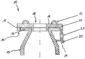
- the single figure shows the side view of the upper part of a vacuum converter in section with a protective device according to the invention.
- the protection device 10 consists essentially of a disc-shaped cover 11, which can be placed on a flange 12 of a vacuum converter 13.
- an annular recess 15 is provided on the underside 14 of the cover 11. The cover 11 engages around the flange 12 of the vacuum converter 13 in a form-fitting manner.
- the cover 11 can be raised, moved and lowered, 16 transporting bracket 17 are arranged on its upper side.
- the cover 11 has a centrally and substantially circular passage 18 through which gases and slag splashes can escape during the atmospheric treatment phase.
- At least one securing means 19 is provided, that the protective device 10 is locked relative to the flange 12.
- a hook 20 may be welded to the outside of the vacuum converter 13.
- the hook 20 in turn can be connected via connecting means 21 releasably connected to the cover 11.
- connecting means 21 chains are particularly conceivable that can be brought to tension with Glasspindelstangen.
Landscapes
- Engineering & Computer Science (AREA)
- Chemical & Material Sciences (AREA)
- Manufacturing & Machinery (AREA)
- Materials Engineering (AREA)
- Metallurgy (AREA)
- Organic Chemistry (AREA)
- Furnace Housings, Linings, Walls, And Ceilings (AREA)
- Treatment Of Steel In Its Molten State (AREA)
Description
- Die vorliegende Erfindung betrifft einen Vakuum - Konverter, umfassend eine Schutzvorrichtung für die Oberfläche eines der Mündung des kippbaren Vakuum-Konverters zugeordneten Flansches.
- Der Vakuum-Konverter ist eine gängige Vorrichtung für die Produktion von Stahlsorten, die durch niedrige oder ultra-niedrige Kohlenstoffgehalte gekennzeichnet sein können. Die metallurgische Behandlung im Vakuum-Konverter wird in die atmosphärische Phase, die gewöhnlich durch das thermodynamische Reaktionsgleichgewicht unter atmosphärischem Druck stattfindet, und in die Vakuumphase unterteilt, in der die Gleichgewichte in der Schmelze bzw. Legierung unter niedrigeren Drücken kontrolliert werden sollen.
- Nach der atmosphärischen Behandlung wird der Vakuum-Konverter durch eine Abdichtabdeckung abgedeckt. Dadurch wird eine Druckreduzierung der in dem Vakuum-Konverter befindlichen Atmosphäre über ein Vakuumpumpensystem ermöglicht.
- Der Wirkungsgrad des Vakuumsystems hängt stark von der Dichtheit zwischen dem Flansch des Konvertergefäßes und der Vakuumabdeckung ab. Es ist das grundlegende technische Problem, die Flanschoberfläche sauber und frei von Metall- oder Schlackenspritzen zu halten. Hohe Oberflächenreinheit reduziert mögliche Luftleckagen und sorgt für die Durchführung der nachfolgenden Vakuumbehandlung mit hoher Genauigkeit und in dem hierfür vorgesehen Zeitintervall.
- Aus der
CN 102719624 A ist eine Spritzschutzabdeckung für einen Sauerstoff-Blas- und Entkarbonisierungs-Vakuum-Raffinationsofen bekannt. Die Spritzschutzabdeckung umfasst einen oberen Deckelring mit einem Durchgangsloch, einen konischen Zylinder und einen Basisring, wobei der obere Abdeckring am oberen Ende des konischen Zylinders angeordnet ist, und die Innenseite des Basisrings am unteren Ende des konischen Zylinders befestigt ist. Die Spritzschutzabdeckung umfasst ferner einen Abdeckring mit einer oberen Abdeckring-Oberplatte, einer Deckel-Deckschlauch-Deckschale und einer reinen Kupferdeckel-Deckelunterplatte. - Die Druckschrift
US 6,830,723 B2 offenbart eine Vorrichtung zur Behandlung von geschmolzenem Metall in einem Behandlungsgefäß mit einer entfernbaren Abdeckung oder Haube. Dichtungsmittel sind zwischen der Abdeckung und dem Behälter vorgesehen, um eine gasdichte Behandlungszone zu schaffen. Die Dichtungsmittel umfassen zusammenpassende Umfangsflansche an dem Behälter und der Abdeckung, wobei der Abdeckflansch zwei beabstandete ringförmige Dichtungsstreifen für die Behälterflansche und einen metallischen ringförmigen Spritzschutz aufweist. Dieser Dichtungsstreifen umfasst einen Wärmedämmstreifen, der aus einem verformbaren faserigen feuerfesten Material ausgebildet ist, um eine gasdichte thermische Barriere zwischen dem Inneren und dem Äußeren des Gefäßes und einem Metallringstreifen zu schaffen, auf dem die Abdeckung auf dem Behälter aufliegt. - Eine Schutzvorrichtung, die geeignet ist, die Oberfläche der Mündung eines einem kippbaren Vakuum - Konverter zgeordneten Flansches geeignet ist, ist aus derUS 3 601 379 A bekannt.
- Es hat sich gezeigt, dass es bei den oben beschriebenen Schutz- und Abdeckvorrichtungen immer wieder zu ungewollten Verzögerungen gekommen ist. Beim Wechseln der Betriebsmodi zwischen der atmosphärischen Phase und der Vakuumphase muss ein Vakuumdeckel auf der Flanschoberfläche der Flanschöffnung des Vakuum-Konverters aufgesetzt werden.
- Hierzu muss die Oberfläche der Flanschöffnung des Vakuum-Konverters aus den oben beschriebenen Gründen möglichst frei von Verkrustungen sein. Um dies sicherstellen zu können und eine leidlich gereinigte Flanschoberfläche zu ermöglichen, müssen hierfür Arbeiter aufwendig gesichert und vor der Hitzestrahlung geschützt werden. Die Anforderungen an den Arbeitsschutz sind dementsprechend hoch und aufwendig, damit die Gesundheit der Arbeiter gewährleistet werden kann. Diese Sicherheitsvorkehrungen sind mit einem erheblichen administrativen Aufwand verbunden. Zudem sind sie zeitaufwendig und wegen des Produktionsausfalls kostenintensiv.
- Es ist daher Aufgabe der vorliegenden Erfindung, eine Schutzvorrichtung zu schaffen, mit der die oben genannten Nachteile überwunden werden können.
- Diese Aufgabe wird durch die im Anspruch 1 angegebenen Merkmale gelöst, insbesondere dadurch, dass die Oberfläche des Flansches mit einer einen zentrischen Durchlass aufweisenden Abdeckung abdeckbar ist, und die Abdeckung an ihrer, dem Konverter zugewandten Unterseite eine den Flansch formschlüssig umgreifende ringförmige Ausnehmung aufweist. Hierdurch wird während der atmosphärischen Behandlung der Schmelze im Konverter die Oberfläche der Flanschöffnung vor umherfliegenden Schlacken- und Schmelzenteilchen wirksam geschützt.
- Um die Oberfläche der Schutzvorrichtung bzw. der Abdeckung zu schützen und ein Säubern zu erleichtern, ist sie mit einer feuerfesten, druckelastischen BeSchichtung versehen. Diese Beschichtung soll Anbackungen, Verkrustungen und Reste von Aufschmelzungen an der Schutzvorrichtung verhindern. Der Einsatzzyklus der Schutzvorrichtung kann dadurch nicht unerheblich verlängert werden.
- Dabei ist vorgesehen, dass der zentrische Durchlass im Wesentlichen den Abmessungen der Konvertermündung entspricht. Dadurch umschließt und schützt die Schutzvorrichtung passgenau die Seitenfläche und die Oberfläche des Flansches.
- Für den Transport der Schutzvorrichtung aus einer Ruheposition in die Arbeitsposition bzw. zum Auf- und Absetzen der Schutzvorrichtung beispielsweise mittels eines Kranes sind an der Oberfläche der Schutzvorrichtung Transportbügel vorgesehen.
- Zur Sicherung der Schutzvorrichtung ist es vorgesehen, die Abdeckung mit mindestens einem Sicherungsmittel zu versehen, das lösbar mit dem Vakuum-Konverter verbunden werden kann.
- Die Ausnehmung der erfindungsgemäßen Schutzvorrichtung kann kegel-, nasen- oder prismenförmig ausgebildet und individuell dem jeweiligen Konverterflansch angepasst sein.
- Die Schutzvorrichtung kann aus einem einfachen, niedrig legierten, preisgünstigen Baustahl bestehen.
- Die Erfindung wird im Folgenden anhand einer beispielhaften Ausführungsform unter Bezugnahme auf die beigefügte Zeichnung näher beschrieben.
- Die einzige Figur zeigt die Seitenansicht des oberen Teils eines Vakuum-Konverters im Schnitt mit einer erfindungsgemäßen Schutzvorrichtung.
- Wie in der Zeichnung dargestellt, besteht die Schutzvorrichtung 10 im Wesentlichen aus einer scheibenförmigen Abdeckung 11, die auf einem Flansch 12 eines Vakuum-Konverters 13 aufgesetzt werden kann. Hierzu ist an der Unterseite 14 der Abdeckung 11 eine ringförmige Ausnehmung 15 vorgesehen. Die Abdeckung 11 umgreift den Flansch 12 des Vakuum-Konverters 13 formschlüssig.
- Damit die Abdeckung 11 angehoben, verfahren und abgesenkt werden kann, sind an ihrer Oberseite 16 Transportbügel 17 angeordnet. Die Abdeckung 11 weist einen zentrisch und im Wesentlichen kreisrunden Durchlass 18 auf, über den während der atmosphärischen Behandlungsphase Gase und Schlackenspritzer austreten können.
- Um die Abdeckung 11 beim Kippen des Vakuum-Konverters 13 zu sichern, ist mindestens ein Sicherungsmittel 19 vorgesehen, dass die Schutzvorrichtung 10 gegenüber dem Flansch 12 arretiert. Hierzu kann an der Außenseite des Vakuum-Konverters 13 beispielsweise ein Haken 20 angeschweißt sein.
- Der Haken 20 wiederum kann über Verbindungsmittel 21 lösbar mit der Abdeckung 11 verbunden werden. Als Verbindungsmittel 21 sind insbesondere Ketten denkbar, die mit Zugspindelstangen auf Spannung gebracht werden können.
-
- 10
- Schutzvorrichtung
- 11
- Abdeckung
- 12
- Flansch
- 13
- Vakuum - Konverter
- 14
- Unterseite
- 15
- ringförmige Ausnehmung
- 16
- Oberseite
- 17
- Transportbügel
- 18
- Durchlass
- 19
- Sicherungsmittel
- 20
- Haken
- 21
- Verbindungsmittel
Claims (5)
- Vakuum - Konverter, umfassend eine Schutzvorrichtung für die Oberfläche eines, der Mündung eines kippbaren Vakuum-Konverters (13) zugeordneten Flansches (12), dadurch gekennzeichnet, dass die Oberfläche des Flansches (12) mit einer einen zentrischen Durchlass aufweisenden Abdeckung (11) abdeckbar ist, und die Abdeckung (11) an ihrer, dem Konverter zugewandten Unterseite (14) eine den Flansch (12) formschlüssig umgreifende ringförmige Ausnehmung (15) aufweist und dass die Oberseite (16) der Abdeckung (11) mit einer feuerfesten, druckelastischen Beschichtung versehen ist.
- Vakuum - Konverter nach Anspruch 1, dadurch gekennzeichnet, dass die Abdeckung (11) an ihrer Oberseite (16) mit Transportbügeln (17) versehen ist.
- Vakuum - Konverter nach Anspruch 1, dadurch gekennzeichnet, dass die Abdeckung (11) mit mindestens einem Sicherungsmittel (19) versehen ist.
- Vakuum - Konverter nach Anspruch 3, dadurch gekennzeichnet, dass das Sicherungsmittel (19) die Abdeckung (11) lösbar mit dem Vakuum-Konverter (13) verbindet.
- Vakuum - Konverter nach Anspruch 1, dadurch gekennzeichnet, dass die Abdeckung (11) aus Baustahl besteht.
Applications Claiming Priority (1)
| Application Number | Priority Date | Filing Date | Title |
|---|---|---|---|
| DE102017112615.5A DE102017112615A1 (de) | 2017-06-08 | 2017-06-08 | Schutzvorrichtung für Vakuum-Konverter |
Publications (2)
| Publication Number | Publication Date |
|---|---|
| EP3412781A1 EP3412781A1 (de) | 2018-12-12 |
| EP3412781B1 true EP3412781B1 (de) | 2019-07-24 |
Family
ID=62567225
Family Applications (1)
| Application Number | Title | Priority Date | Filing Date |
|---|---|---|---|
| EP18173958.2A Active EP3412781B1 (de) | 2017-06-08 | 2018-05-24 | Schutzvorrichtung für vakuum-konverter |
Country Status (2)
| Country | Link |
|---|---|
| EP (1) | EP3412781B1 (de) |
| DE (1) | DE102017112615A1 (de) |
Families Citing this family (1)
| Publication number | Priority date | Publication date | Assignee | Title |
|---|---|---|---|---|
| CN114754142A (zh) * | 2022-04-21 | 2022-07-15 | 温州云帆泵业有限公司 | 真空转换器的生产方法 |
Family Cites Families (5)
| Publication number | Priority date | Publication date | Assignee | Title |
|---|---|---|---|---|
| DE1758562B1 (de) * | 1968-06-27 | 1972-08-24 | Demag Ag | Metallurgisches Gefaess,insbesondere Stahlwerkskonverter |
| DE2534331C3 (de) * | 1975-08-01 | 1982-10-07 | Mannesmann AG, 4000 Düsseldorf | Mündungsschutz für metallurgische Gefäße, insbesondere für Stahlwerkskonverter |
| DE19749829A1 (de) * | 1997-11-11 | 1999-05-12 | Intocast Ag | Metallurgisches Gefäß |
| US6830723B2 (en) | 2001-10-01 | 2004-12-14 | Alcan International Limited | Apparatus for treating molten metal having a sealed treatment zone |
| CN102719624A (zh) | 2012-06-27 | 2012-10-10 | 山西太钢不锈钢股份有限公司 | 一种吹氧脱碳真空精炼炉防溅罩 |
-
2017
- 2017-06-08 DE DE102017112615.5A patent/DE102017112615A1/de not_active Withdrawn
-
2018
- 2018-05-24 EP EP18173958.2A patent/EP3412781B1/de active Active
Non-Patent Citations (1)
| Title |
|---|
| None * |
Also Published As
| Publication number | Publication date |
|---|---|
| EP3412781A1 (de) | 2018-12-12 |
| DE102017112615A1 (de) | 2018-12-13 |
Similar Documents
| Publication | Publication Date | Title |
|---|---|---|
| DE69202089T2 (de) | Kühlsystem eines ein Innenteil enthaltendes Ofengewölbes. | |
| DE3886379T2 (de) | Kühlsystem und -verfahren zum Handhaben von geschmolzenen metallenthaltenden Gefässen. | |
| EP0193948B1 (de) | Vorrichtung und Verfahren zum Warmhalten von flüssigen Metallschmelzen | |
| DE2709727A1 (de) | Einrichtung zum auswechseln von giessrohren an giessgefaesse beim stranggiessen | |
| DE2256269B2 (de) | Metallerzeugungsanlage mit einem kippbaren konverter | |
| EP3412781B1 (de) | Schutzvorrichtung für vakuum-konverter | |
| WO1999054511A1 (de) | Variabel einsetzbare kombilanze mit verschiebbaren brenner- und blaslanzenkörpern | |
| DE2017469A1 (de) | Anlage zum Stranggießen sowie kontinuierliches Gießverfahren unter Verwendung dieser Anlage | |
| DE7928208U1 (de) | Vorrichtung zur durchfuehrung metallurgischer reaktionen in einer pfanne | |
| CH625984A5 (de) | ||
| DE2921702A1 (de) | Elektro-metallschmelzofen | |
| DE4042330A1 (de) | Bodenelektrode eines glasschmelzofens | |
| DE1278459C2 (de) | Tiegel oder konverter mit einem anschliessbaren, heb- und senkbaren essenteil | |
| DE2247185A1 (de) | Verfahren und vorrichtung zum oeffnen eines unbetaetigbaren verschlusskoerpers des bodenausgusses eines giessgefaesses | |
| EP0581203A1 (de) | Abdichtung eines umlaufenden Spaltes zwischen Stahlgiesspfanne und Pfannenhaube | |
| DE68901876T2 (de) | Pfanne zum transport von fluessigen metallen. | |
| DE2361344A1 (de) | Verfahren und vorrichtung zum eingiessen von metall in eine stranggiesskokille | |
| AT393694B (de) | Konverter fuer die stahlerzeugung | |
| EP0916740A1 (de) | Vakuummetallurgisches Gefäss | |
| EP0025028B2 (de) | Pfannenstand zur Durchführung metallurgischer Behandlungen von Stahlschmelzen | |
| DE3204034C2 (de) | ||
| DE1802197A1 (de) | Rinnenofen zur Behandlung von Metallschmelzen | |
| EP0956917B1 (de) | Metallurgisches Gefäss | |
| DE2438711A1 (de) | Abgussvorrichtung fuer schmelzen | |
| DE19747317A1 (de) | Behandlungsgefäß für Metallschmelzen |
Legal Events
| Date | Code | Title | Description |
|---|---|---|---|
| STAA | Information on the status of an ep patent application or granted ep patent |
Free format text: STATUS: EXAMINATION IS IN PROGRESS |
|
| PUAI | Public reference made under article 153(3) epc to a published international application that has entered the european phase |
Free format text: ORIGINAL CODE: 0009012 |
|
| 17P | Request for examination filed |
Effective date: 20180524 |
|
| AK | Designated contracting states |
Kind code of ref document: A1 Designated state(s): AL AT BE BG CH CY CZ DE DK EE ES FI FR GB GR HR HU IE IS IT LI LT LU LV MC MK MT NL NO PL PT RO RS SE SI SK SM TR |
|
| AX | Request for extension of the european patent |
Extension state: BA ME |
|
| GRAP | Despatch of communication of intention to grant a patent |
Free format text: ORIGINAL CODE: EPIDOSNIGR1 |
|
| STAA | Information on the status of an ep patent application or granted ep patent |
Free format text: STATUS: GRANT OF PATENT IS INTENDED |
|
| INTG | Intention to grant announced |
Effective date: 20190107 |
|
| GRAJ | Information related to disapproval of communication of intention to grant by the applicant or resumption of examination proceedings by the epo deleted |
Free format text: ORIGINAL CODE: EPIDOSDIGR1 |
|
| GRAP | Despatch of communication of intention to grant a patent |
Free format text: ORIGINAL CODE: EPIDOSNIGR1 |
|
| INTG | Intention to grant announced |
Effective date: 20190131 |
|
| GRAS | Grant fee paid |
Free format text: ORIGINAL CODE: EPIDOSNIGR3 |
|
| GRAA | (expected) grant |
Free format text: ORIGINAL CODE: 0009210 |
|
| STAA | Information on the status of an ep patent application or granted ep patent |
Free format text: STATUS: THE PATENT HAS BEEN GRANTED |
|
| AK | Designated contracting states |
Kind code of ref document: B1 Designated state(s): AL AT BE BG CH CY CZ DE DK EE ES FI FR GB GR HR HU IE IS IT LI LT LU LV MC MK MT NL NO PL PT RO RS SE SI SK SM TR |
|
| RBV | Designated contracting states (corrected) |
Designated state(s): AL AT BE BG CH CY CZ DE DK EE ES FI FR GB GR HR HU IE IS IT LI LT LU LV MC MK MT NL NO PL PT RO RS SE SI SK SM TR |
|
| REG | Reference to a national code |
Ref country code: GB Ref legal event code: FG4D Free format text: NOT ENGLISH |
|
| REG | Reference to a national code |
Ref country code: CH Ref legal event code: EP |
|
| REG | Reference to a national code |
Ref country code: DE Ref legal event code: R096 Ref document number: 502018000100 Country of ref document: DE |
|
| REG | Reference to a national code |
Ref country code: AT Ref legal event code: REF Ref document number: 1158259 Country of ref document: AT Kind code of ref document: T Effective date: 20190815 |
|
| REG | Reference to a national code |
Ref country code: IE Ref legal event code: FG4D Free format text: LANGUAGE OF EP DOCUMENT: GERMAN |
|
| REG | Reference to a national code |
Ref country code: NL Ref legal event code: MP Effective date: 20190724 |
|
| REG | Reference to a national code |
Ref country code: LT Ref legal event code: MG4D |
|
| PG25 | Lapsed in a contracting state [announced via postgrant information from national office to epo] |
Ref country code: SE Free format text: LAPSE BECAUSE OF FAILURE TO SUBMIT A TRANSLATION OF THE DESCRIPTION OR TO PAY THE FEE WITHIN THE PRESCRIBED TIME-LIMIT Effective date: 20190724 Ref country code: HR Free format text: LAPSE BECAUSE OF FAILURE TO SUBMIT A TRANSLATION OF THE DESCRIPTION OR TO PAY THE FEE WITHIN THE PRESCRIBED TIME-LIMIT Effective date: 20190724 Ref country code: LT Free format text: LAPSE BECAUSE OF FAILURE TO SUBMIT A TRANSLATION OF THE DESCRIPTION OR TO PAY THE FEE WITHIN THE PRESCRIBED TIME-LIMIT Effective date: 20190724 Ref country code: FI Free format text: LAPSE BECAUSE OF FAILURE TO SUBMIT A TRANSLATION OF THE DESCRIPTION OR TO PAY THE FEE WITHIN THE PRESCRIBED TIME-LIMIT Effective date: 20190724 Ref country code: BG Free format text: LAPSE BECAUSE OF FAILURE TO SUBMIT A TRANSLATION OF THE DESCRIPTION OR TO PAY THE FEE WITHIN THE PRESCRIBED TIME-LIMIT Effective date: 20191024 Ref country code: NL Free format text: LAPSE BECAUSE OF FAILURE TO SUBMIT A TRANSLATION OF THE DESCRIPTION OR TO PAY THE FEE WITHIN THE PRESCRIBED TIME-LIMIT Effective date: 20190724 Ref country code: PT Free format text: LAPSE BECAUSE OF FAILURE TO SUBMIT A TRANSLATION OF THE DESCRIPTION OR TO PAY THE FEE WITHIN THE PRESCRIBED TIME-LIMIT Effective date: 20191125 Ref country code: NO Free format text: LAPSE BECAUSE OF FAILURE TO SUBMIT A TRANSLATION OF THE DESCRIPTION OR TO PAY THE FEE WITHIN THE PRESCRIBED TIME-LIMIT Effective date: 20191024 |
|
| PG25 | Lapsed in a contracting state [announced via postgrant information from national office to epo] |
Ref country code: RS Free format text: LAPSE BECAUSE OF FAILURE TO SUBMIT A TRANSLATION OF THE DESCRIPTION OR TO PAY THE FEE WITHIN THE PRESCRIBED TIME-LIMIT Effective date: 20190724 Ref country code: IS Free format text: LAPSE BECAUSE OF FAILURE TO SUBMIT A TRANSLATION OF THE DESCRIPTION OR TO PAY THE FEE WITHIN THE PRESCRIBED TIME-LIMIT Effective date: 20191124 Ref country code: GR Free format text: LAPSE BECAUSE OF FAILURE TO SUBMIT A TRANSLATION OF THE DESCRIPTION OR TO PAY THE FEE WITHIN THE PRESCRIBED TIME-LIMIT Effective date: 20191025 Ref country code: LV Free format text: LAPSE BECAUSE OF FAILURE TO SUBMIT A TRANSLATION OF THE DESCRIPTION OR TO PAY THE FEE WITHIN THE PRESCRIBED TIME-LIMIT Effective date: 20190724 Ref country code: AL Free format text: LAPSE BECAUSE OF FAILURE TO SUBMIT A TRANSLATION OF THE DESCRIPTION OR TO PAY THE FEE WITHIN THE PRESCRIBED TIME-LIMIT Effective date: 20190724 Ref country code: ES Free format text: LAPSE BECAUSE OF FAILURE TO SUBMIT A TRANSLATION OF THE DESCRIPTION OR TO PAY THE FEE WITHIN THE PRESCRIBED TIME-LIMIT Effective date: 20190724 |
|
| PG25 | Lapsed in a contracting state [announced via postgrant information from national office to epo] |
Ref country code: TR Free format text: LAPSE BECAUSE OF FAILURE TO SUBMIT A TRANSLATION OF THE DESCRIPTION OR TO PAY THE FEE WITHIN THE PRESCRIBED TIME-LIMIT Effective date: 20190724 |
|
| PG25 | Lapsed in a contracting state [announced via postgrant information from national office to epo] |
Ref country code: IT Free format text: LAPSE BECAUSE OF FAILURE TO SUBMIT A TRANSLATION OF THE DESCRIPTION OR TO PAY THE FEE WITHIN THE PRESCRIBED TIME-LIMIT Effective date: 20190724 Ref country code: RO Free format text: LAPSE BECAUSE OF FAILURE TO SUBMIT A TRANSLATION OF THE DESCRIPTION OR TO PAY THE FEE WITHIN THE PRESCRIBED TIME-LIMIT Effective date: 20190724 Ref country code: DK Free format text: LAPSE BECAUSE OF FAILURE TO SUBMIT A TRANSLATION OF THE DESCRIPTION OR TO PAY THE FEE WITHIN THE PRESCRIBED TIME-LIMIT Effective date: 20190724 Ref country code: PL Free format text: LAPSE BECAUSE OF FAILURE TO SUBMIT A TRANSLATION OF THE DESCRIPTION OR TO PAY THE FEE WITHIN THE PRESCRIBED TIME-LIMIT Effective date: 20190724 Ref country code: EE Free format text: LAPSE BECAUSE OF FAILURE TO SUBMIT A TRANSLATION OF THE DESCRIPTION OR TO PAY THE FEE WITHIN THE PRESCRIBED TIME-LIMIT Effective date: 20190724 |
|
| PG25 | Lapsed in a contracting state [announced via postgrant information from national office to epo] |
Ref country code: SM Free format text: LAPSE BECAUSE OF FAILURE TO SUBMIT A TRANSLATION OF THE DESCRIPTION OR TO PAY THE FEE WITHIN THE PRESCRIBED TIME-LIMIT Effective date: 20190724 Ref country code: SK Free format text: LAPSE BECAUSE OF FAILURE TO SUBMIT A TRANSLATION OF THE DESCRIPTION OR TO PAY THE FEE WITHIN THE PRESCRIBED TIME-LIMIT Effective date: 20190724 Ref country code: CZ Free format text: LAPSE BECAUSE OF FAILURE TO SUBMIT A TRANSLATION OF THE DESCRIPTION OR TO PAY THE FEE WITHIN THE PRESCRIBED TIME-LIMIT Effective date: 20190724 Ref country code: IS Free format text: LAPSE BECAUSE OF FAILURE TO SUBMIT A TRANSLATION OF THE DESCRIPTION OR TO PAY THE FEE WITHIN THE PRESCRIBED TIME-LIMIT Effective date: 20200224 |
|
| REG | Reference to a national code |
Ref country code: DE Ref legal event code: R097 Ref document number: 502018000100 Country of ref document: DE |
|
| PLBE | No opposition filed within time limit |
Free format text: ORIGINAL CODE: 0009261 |
|
| STAA | Information on the status of an ep patent application or granted ep patent |
Free format text: STATUS: NO OPPOSITION FILED WITHIN TIME LIMIT |
|
| PG2D | Information on lapse in contracting state deleted |
Ref country code: IS |
|
| 26N | No opposition filed |
Effective date: 20200603 |
|
| PG25 | Lapsed in a contracting state [announced via postgrant information from national office to epo] |
Ref country code: MC Free format text: LAPSE BECAUSE OF FAILURE TO SUBMIT A TRANSLATION OF THE DESCRIPTION OR TO PAY THE FEE WITHIN THE PRESCRIBED TIME-LIMIT Effective date: 20190724 |
|
| REG | Reference to a national code |
Ref country code: BE Ref legal event code: MM Effective date: 20200531 |
|
| PG25 | Lapsed in a contracting state [announced via postgrant information from national office to epo] |
Ref country code: LU Free format text: LAPSE BECAUSE OF NON-PAYMENT OF DUE FEES Effective date: 20200524 |
|
| PG25 | Lapsed in a contracting state [announced via postgrant information from national office to epo] |
Ref country code: FR Free format text: LAPSE BECAUSE OF NON-PAYMENT OF DUE FEES Effective date: 20200531 Ref country code: IE Free format text: LAPSE BECAUSE OF NON-PAYMENT OF DUE FEES Effective date: 20200524 |
|
| PG25 | Lapsed in a contracting state [announced via postgrant information from national office to epo] |
Ref country code: BE Free format text: LAPSE BECAUSE OF NON-PAYMENT OF DUE FEES Effective date: 20200531 |
|
| REG | Reference to a national code |
Ref country code: CH Ref legal event code: PL |
|
| PG25 | Lapsed in a contracting state [announced via postgrant information from national office to epo] |
Ref country code: LI Free format text: LAPSE BECAUSE OF NON-PAYMENT OF DUE FEES Effective date: 20210531 Ref country code: CH Free format text: LAPSE BECAUSE OF NON-PAYMENT OF DUE FEES Effective date: 20210531 |
|
| PG25 | Lapsed in a contracting state [announced via postgrant information from national office to epo] |
Ref country code: MT Free format text: LAPSE BECAUSE OF FAILURE TO SUBMIT A TRANSLATION OF THE DESCRIPTION OR TO PAY THE FEE WITHIN THE PRESCRIBED TIME-LIMIT Effective date: 20190724 Ref country code: CY Free format text: LAPSE BECAUSE OF FAILURE TO SUBMIT A TRANSLATION OF THE DESCRIPTION OR TO PAY THE FEE WITHIN THE PRESCRIBED TIME-LIMIT Effective date: 20190724 |
|
| PG25 | Lapsed in a contracting state [announced via postgrant information from national office to epo] |
Ref country code: MK Free format text: LAPSE BECAUSE OF FAILURE TO SUBMIT A TRANSLATION OF THE DESCRIPTION OR TO PAY THE FEE WITHIN THE PRESCRIBED TIME-LIMIT Effective date: 20190724 |
|
| GBPC | Gb: european patent ceased through non-payment of renewal fee |
Effective date: 20220524 |
|
| PG25 | Lapsed in a contracting state [announced via postgrant information from national office to epo] |
Ref country code: GB Free format text: LAPSE BECAUSE OF NON-PAYMENT OF DUE FEES Effective date: 20220524 |
|
| P01 | Opt-out of the competence of the unified patent court (upc) registered |
Effective date: 20230707 |
|
| PG25 | Lapsed in a contracting state [announced via postgrant information from national office to epo] |
Ref country code: SI Free format text: LAPSE BECAUSE OF FAILURE TO SUBMIT A TRANSLATION OF THE DESCRIPTION OR TO PAY THE FEE WITHIN THE PRESCRIBED TIME-LIMIT Effective date: 20190724 |
|
| REG | Reference to a national code |
Ref country code: AT Ref legal event code: MM01 Ref document number: 1158259 Country of ref document: AT Kind code of ref document: T Effective date: 20230524 |
|
| PG25 | Lapsed in a contracting state [announced via postgrant information from national office to epo] |
Ref country code: AT Free format text: LAPSE BECAUSE OF NON-PAYMENT OF DUE FEES Effective date: 20230524 |
|
| PG25 | Lapsed in a contracting state [announced via postgrant information from national office to epo] |
Ref country code: AT Free format text: LAPSE BECAUSE OF NON-PAYMENT OF DUE FEES Effective date: 20230524 |
|
| PGFP | Annual fee paid to national office [announced via postgrant information from national office to epo] |
Ref country code: DE Payment date: 20250521 Year of fee payment: 8 |
|
| PGFP | Annual fee paid to national office [announced via postgrant information from national office to epo] |
Ref country code: AT Payment date: 20260410 Year of fee payment: 5 |