EP3416876B1 - Plaque d'usure conçue pour une chenille d'un véhicule chenillé, chenille et engin de chantier - Google Patents
Plaque d'usure conçue pour une chenille d'un véhicule chenillé, chenille et engin de chantier Download PDFInfo
- Publication number
- EP3416876B1 EP3416876B1 EP17704774.3A EP17704774A EP3416876B1 EP 3416876 B1 EP3416876 B1 EP 3416876B1 EP 17704774 A EP17704774 A EP 17704774A EP 3416876 B1 EP3416876 B1 EP 3416876B1
- Authority
- EP
- European Patent Office
- Prior art keywords
- wear pad
- accordance
- longitudinal direction
- wear
- crawler track
- Prior art date
- Legal status (The legal status is an assumption and is not a legal conclusion. Google has not performed a legal analysis and makes no representation as to the accuracy of the status listed.)
- Active
Links
Images


Classifications
-
- B—PERFORMING OPERATIONS; TRANSPORTING
- B62—LAND VEHICLES FOR TRAVELLING OTHERWISE THAN ON RAILS
- B62D—MOTOR VEHICLES; TRAILERS
- B62D55/00—Endless track vehicles
- B62D55/08—Endless track units; Parts thereof
- B62D55/18—Tracks
- B62D55/26—Ground engaging parts or elements
- B62D55/28—Ground engaging parts or elements detachable
-
- B—PERFORMING OPERATIONS; TRANSPORTING
- B62—LAND VEHICLES FOR TRAVELLING OTHERWISE THAN ON RAILS
- B62D—MOTOR VEHICLES; TRAILERS
- B62D55/00—Endless track vehicles
- B62D55/08—Endless track units; Parts thereof
- B62D55/18—Tracks
- B62D55/26—Ground engaging parts or elements
- B62D55/275—Ground engaging parts or elements with street plate, i.e. means to prevent tread from cutting into road surface
-
- B—PERFORMING OPERATIONS; TRANSPORTING
- B62—LAND VEHICLES FOR TRAVELLING OTHERWISE THAN ON RAILS
- B62D—MOTOR VEHICLES; TRAILERS
- B62D55/00—Endless track vehicles
- B62D55/32—Assembly, disassembly, repair or servicing of endless-track systems
Definitions
- the invention relates to an exchangeable wear pad for a crawler belt of a tracked vehicle, according to the preamble of claim 1.
- Exchangeable wear pads for crawlers are known from the prior art, which can be releasably attached to an intermediate plate of the crawler.
- the wear pads generally have four outwardly protruding screw bolts of fastening screws that are spaced apart in the longitudinal direction of the wear pad.
- the fastening screws are passed through reinforcement rails and secured against twisting in a suitable manner.
- the reinforcement rails are encased by the wear pad material with fastening screws arranged at their ends.
- the disadvantage here is that the wear pad material also settles under the reinforcement rail when it is cast around.
- This has the disadvantage that the screw connections with an intermediate plate loosen again during operation due to the soft polyurethane material between the reinforcement rail and the intermediate plate, so that the screw connections have to be retightened regularly.
- the polyurethane material located between the reinforcement rail and the intermediate plate prevents the pre-tensioning of the screw connection from being permanently maintained. It goes without saying that with up to 50 wear pads per crawler track of a chassis and with four chassis per machine, the time required for retensioning the screw connections is considerable, so that increased costs and an increased time requirement arise.
- a contact collar of the reinforcement rail is essentially flush with the wear pad material of the wear pad, so that the wear pad can be rigidly attached to an intermediate plate via the screw connection.
- Two projections extending in the longitudinal direction of the wear pad protrude from the underside of the wear pad, which protrusions into the intermediate plate, as from Fig. 10 visible to intervene.
- alternating transverse forces arise which act on the fastening means and can also lead to premature loosening of the fastening means between the intermediate plate and the crawler belt and between the wear pad and the intermediate plate.
- An inclined position of the construction machine also generates high transverse forces which have to be absorbed by the fastening means of the wear pad and the fastening means of the intermediate plate.
- the invention is therefore based on the object of creating a wear pad for a track of the type mentioned, as well as a track and a construction machine, with which the durability of the screw connections, a wear pad and the manufacturing costs and the time required for assembly and disassembly are improved the wear pad and thus the maintenance costs can be reduced.
- the invention advantageously provides that the projection of the wear pad on the underside facing the track link for at least partial engagement in a recess of the track link adapted to the protrusion has an outer contour that runs at least partially at an angle deviating from the longitudinal direction of the wear pad.
- transverse forces can be absorbed, which act in particular when steering the tracked vehicle in the longitudinal direction of the wear pad.
- the deflection forces and / or inclination of the crawler belt transversely to the direction of movement of the crawler belt form an alternating load on the fastening means, so that the screw connection of the wear pads can loosen under the action of changing transverse forces and may require the screw connections to be retightened.
- the outer contour of the projection protruding on the underside of the wear pad which extends at least partially at an angle deviating from the longitudinal direction of the wear pad, absorbs the transverse forces and thus relieves the fastening means completely or at least to a considerable extent from the alternating load. In this way, it is possible to use only two fastening means that are mutually spaced apart in the longitudinal direction of the wear pad, so that the assembly effort for mounting and dismounting of the wear pad is reduced, almost halved, and the manufacturing costs for the wear pad are also reduced.
- the angle is ⁇ 0 ° and ⁇ 90 °.
- the angle is preferably in the range from 20 ° to 70 ° and particularly preferably 30 ° to 60 °.
- the projection preferably has two side surfaces extending substantially in the longitudinal direction and two end surfaces preferably extending substantially perpendicular to the longitudinal direction.
- the side surfaces of the projection here have the angle according to the invention to the longitudinal direction of the wear pad in order to absorb transverse forces.
- the side surfaces can have a constant distance in the longitudinal direction and thus run parallel to one another. The distance between the side surfaces can also vary in the longitudinal direction.
- Another advantage is that an intermediate plate is no longer required between the track link and the wear pad. This eliminates the need for further fastening means between the crawler belt and the intermediate plate, so that the assembly and disassembly effort is considerably reduced overall.
- the engagement of the projection in a recess which is complementary to the projection and which forms a form fit at least in the longitudinal direction of the wear pad.
- the wear pad contains at least one reinforcement element which is at least predominantly enclosed or encapsulated by wear pad material.
- the reinforcement element increases the rigidity of the wear pad, in particular in the form of a reinforcement rail and enables rigid attachment to the track links without the need to re-tension the fastening means before the running surface of the wear pad is completely worn.
- the wear pad can have at least two fastening means which are arranged at a distance from one another in the longitudinal direction of the wear pad and which are used to fasten the wear pad to the track link.
- the fastening means are preferably arranged in the vicinity of the free ends of the wear pad on the underside in the longitudinal direction.
- the reinforcement element is integrated into the at least one projection of the wear pad. In this way, the part of the wear pad that does not form the projection forms a wear layer that can be almost completely used up.
- the fastening means can be integrated in the reinforcement element and can also be in one piece with the reinforcement element. Such fasteners enable a secure attachment of the wear pad over the entire service life of the wear pad.
- the reinforcement element terminates essentially flush with the wear pad material in the longitudinal direction of the wear pad at at least two longitudinally spaced locations of the reinforcement element embedded in the projection. This makes it possible for the reinforcement element to be in direct contact with the track link at the two spaced-apart locations when the fastening means are tensioned, so that the pretensioning of the screw connection is permanently maintained and the fastening means do not loosen during the service life.
- the at least two locations of the reinforcement element embedded in the projection which are essentially flush with the wear pad material, are arranged in the area of the fastening means of the reinforcement element. This has the advantage that the prestress applied by the fastening means is highest at the points of the reinforcement element that are in contact with the track link.
- the longitudinally extending wear pad has a length to width ratio between 2.5 and 5, preferably in the range between 3.5 and 4. In this way, the gaps between two wear pads of the track can be kept small and at the same time a larger footprint for the track can be achieved.
- the wear pad protrudes from the crawler link at least on the outside of the crawler belt, seen transversely to the direction of movement. In this way, the track link z. B. on curbs protected from damage.
- the ratio of the width transverse to the longitudinal direction of a wear pad to the deflection radius of the crawler belt is in the range between 0.2 and 0.4, preferably between 0.25 and 0.3.
- One of those Ratio, also called pitch, has the advantage that the smooth running of the crawler belt can be improved.
- the projections of the wear pad do not run linearly with respect to the longitudinal direction of the wear pad, namely at least partially curved or wave-shaped to the longitudinal direction of the wear pad.
- Such a contour of the projections enables a form fit with the track link, with which high transverse force components can be absorbed that do not only occur transversely to the direction of movement of the wear pad.
- the projections of the wear pad extend linearly in the longitudinal direction of the wear pad, specifically at least partially at an angle or at an angle to the longitudinal direction of the wear pad.
- the outer contour of the projection in the longitudinal direction can have a zigzag shape or a sawtooth shape in plan view.
- transverse force components in different directions emanating from the crawler belt can be absorbed and the fastening means, in particular, can be relieved of transverse forces completely or at least to a substantial extent.
- the projections of the wear pad have a different width in the longitudinal direction of the wear pad, or are stepped in the longitudinal direction on the end faces and / or outer edges.
- the material of the wear pad consists of an elastomer, preferably a polyurethane, which is preferably colored through with a light luminous color. Due to the through-coloring, the bright luminous color is retained even if the wear pad wears out.
- the invention also relates to a crawler belt for tracked vehicles with several wear pads of the type described above, as well as a construction machine with such a crawler belt.
- Fig. 9 shows an embodiment of a crawler belt 2 that runs on replaceable wear pads 1.
- Such endlessly revolving in the direction of movement 44 Crawler chains 2 are used in the chassis of a tracked vehicle, e.g. B. a road milling machine is required.
- the crawler belt 2 runs with its chain links 3 and crawler chain links 4 around two pulleys 8 and 10, one of which is driven.
- the deflection radius r is measured on the outer radius of the crawler belt 2, which corresponds to approximately half the height of the crawler belt 2.
- the ratio of the width of the wear pad 1 in the direction of movement 44 to the deflection radius r is in the range between 0.2 and 0.4, preferably between 0.25 and 0.3.
- the height of the crawler belt is, for example, about 600 mm.
- the ratio of length to width of wear pad 1 is in the range between 2.5 and 5, preferably in the range between 3.5 and 4.
- the length of wear pad 1 is approximately 300, for example mm, the width approx. 80 mm.
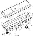
- Figs. 1 to 3 show a first embodiment of a track link 4 according to the invention with a wear pad 1 attached directly to track link 4 without an intermediate plate 6, in a perspective view.
- Fastening means 26 and fastening holes 20 coaxial with this for fastening screws 28 for fastening the exchangeable wear pad 1 on the track link 4 adapted to the wear pad 1 are provided in the wear pad 1.
- the crawler track link 4 has through holes 32, which are arranged coaxially to the fastening holes 20 of the wear pad 1, for receiving the fastening screws 28.
- the fastening means 26 are preferably arranged in the longitudinal direction of the wear pad 1 and preferably in the region of the free ends.
- the crawler links 4 require according to Fig. 10 no intermediate plate 6 and are articulated via bearing eyes 50, 52 with each other, the bearing eyes 50 engage in the bearing eyes 52 of an adjacent track link 4 and there, for. B. via a not shown Bearing bolts are articulated together.
- the wear pad 1 is preferably fastened to the track link 4 with only two fastening screws 28.
- Figs. 1 and 3 shows a wear pad 1 with a projection 30 with an outer contour which is curved in plan view and which can also be made essentially elliptical.
- the wear pads 1 of all embodiments preferably consist of an optionally reinforced wear pad material 36, preferably an elastomer material, e.g. B. polyurethane, which, according to a particularly preferred embodiment, is colored through with a light luminous color, preferably signal yellow (RAL 1003).
- an elastomer material e.g. B. polyurethane
- a light luminous color preferably signal yellow (RAL 1003).
- the projection 30 counteracts Fig. 2 does not have to end flush with the front edges of the wear pad 1 in the longitudinal direction 34, but can also end just behind the fastening holes 20.
- the wear pad 1 can preferably have cast-in reinforcing elements 18, which preferably run in the longitudinal direction 34 of the wear pad 1.
- only one reinforcement element 18 is arranged in the wear pad 1.
- fastening means 26 can be anchored, which cooperate with fastening screws 28 through the through bores 20 of the reinforcement element 18.
- the fastening means 26 can alternatively also consist of screw bolts protruding with respect to the wear pad 1, which are screwed onto the inside of a crawler link 4 with a nut.
- the wear pads 1 have a running surface 14 on their outside, as well as an underside 16 facing the track link 4, which runs essentially parallel to the running surface 14.
- the fastening means 26 are suitable for receiving fastening screws 28 that can be screwed in from the underside 16 of the wear pad 1.
- the track links 4 have suitable through bores 32 which run coaxially to the fastening holes 20 and the fastening means 26 of the wear pad 1. It is essential that at least a part 22 of the reinforcing element 18 rests directly on the track link 4 in the assembled state of the wear pad 1 or is flush with the wear pad material 36.
- the reinforcing element 18 in the wear pad 1, e.g. B. in the form of a reinforcement rail, runs in the first and all further exemplary embodiments in at least one projection 30 protruding from the underside 16 on the underside 16 of the wear pad 1.
- the reinforcing element 18 is preferably only provided in the longitudinally extending projection 30 and can follow its contour, in the sense that the reinforcing element 18 is essentially adapted to the outer contour of the projection 30 in the longitudinal direction 34. If possible, as for example in the embodiment of Figs. 1 to 3 6, 6, the reinforcing element 18 can also run essentially in a straight line in the longitudinal direction 34.
- the reinforcement element 18 itself can also form part of the projection 30.
- the projection 30 z. B. can also be divided into two or more projections 30 in the longitudinal direction 34, or that two projections 30 run essentially parallel to one another on the underside 16 of the wear pad 1.
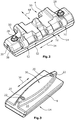
- Fig. 4 shows a perspective view of a wear pad 1 with a projection 30 which is wave-shaped in plan view and protrudes from the underside 16 of the wear pad.
- the underside 16 rests on the track link 4, the projection 30 engaging in a corresponding recess 38 of the track link 4.
- the respective recess 38 of the crawler link 4 is the respective contour and shape of the projections 30, as they are from the Figs. 1 to 5 can be seen, adjusted.
- the projection 30 is at least partially in engagement with the recess 38 in such a way that there is a form fit at least in the longitudinal direction 34 of the wear pad 1. This does not require that the projection 30 completely match the contour of the recess 38.
- the projection 30 is designed to be complementary to the recess 38 of the track link 4.
- the reinforcing element 18 of Fig. 5 can also have a recess corresponding to the recess 46, into which the preferably complementary projection of the track link 4 can engage with exclusively metallic contact, if necessary.
- the fastening holes 20 of the wear pad 1 are coaxial with the through bores 32 of the track link.
- the reinforcement element 18 terminates essentially flush with the wear pad material 36 at at least two points spaced apart in the longitudinal direction 34.
- the part 22 of the reinforcement element 18, which is essentially flush with the wear pad material 36, is preferably coaxial with the fastening hole 20 of the wear pad 1.
- Fig. 6 shows a longitudinal section in the longitudinal direction 34 through the wear pad and the reinforcement element 18 integrated in the projection 30.
- Fig. 7 shows a possible embodiment of an anti-twist device for the fastening means 26, which can be received sunk in the reinforcing element 18.
- the fastening means 26 can also be integral with the reinforcing element 18, or on this z. B. be attached by a non-releasable connection.
- a protective cap 40 is preferably seated on the fastening means 26, which on the one hand creates a clearance for the free end of the fastening screw 28 when the reinforcement element is cast with the wear pad material 36 and prevents wear pad material 36 from penetrating the thread of the fastening means 26.
- the fastening means 26 can also consist of a cap nut or a rivet nut.
- the part 22 of the reinforcing element 18 which is in contact with the track link 4 is designed as an annular collar coaxial with the fastening hole 20.
- the replaceable wear pads 1 according to the prior art are, as from Fig. 10 can be seen, releasably fastened via an intermediate plate 6 on chain links 3 of the endlessly rotating crawler belt 2, which are coupled to one another in an articulated manner.
- Fig. 10 shows a wear pad 1 according to the prior art in a perspective view with the intermediate plate 6 underneath, which in turn is fastened to the chain links 3.
- a total of four fastening screws 24 are used to fasten the wear pad 1 on the intermediate plate 6 and another four fastening screws 27 are screwed through through holes 35 of the intermediate plate 6 and through holes 33 with two chain links 3 running parallel to one another.
- Figs. 1 to 8 do not require an intermediate plate 6 and can be fastened in this way with just two fastening screws 28 that the screw connections are largely relieved of transverse forces.
- the crawler belt 2 of the embodiments of Figs. 1 to 8 corresponds to the representation of Fig. 9 with the exception that the intermediate plate 6 and the chain links 3 are replaced by track links 4.
Landscapes
- Engineering & Computer Science (AREA)
- Chemical & Material Sciences (AREA)
- Combustion & Propulsion (AREA)
- Transportation (AREA)
- Mechanical Engineering (AREA)
- Railway Tracks (AREA)
- Devices For Conveying Motion By Means Of Endless Flexible Members (AREA)
- Component Parts Of Construction Machinery (AREA)
- Road Repair (AREA)
- Body Structure For Vehicles (AREA)
Claims (15)
- Plaque d'usure pour une chenille (2) d'un véhicule à chenilles, dans laquelle- la plaque d'usure (1) comporte une surface de roulement extérieure (14) et une face inférieure (16), opposée à la surface de roulement (14), d'où dépasse au moins une saillie (30),- la plaque d'usure (1) comporte des moyens de fixation (26) pour la fixation à la chenille (2),- le matériau de plaque d'usure (36) de la plaque d'usure (1) est constitué d'un élastomère, de préférence un polyuréthane,- la plaque d'usure (1) contient au moins un élément de renforcement (18), lequel est au moins principalement entouré ou enrobé par le matériau de plaque d'usure (36)caractérisée en ce que la saillie de la plaque d'usure (1) comporte sur la face inférieure (16) tournée vers un maillon de chenille (4) de la chenille (2) un contour pour entrer en prise au moins partiellement sur une dépression du maillon de chenille (4) adaptée à la saillie, lequel s'étend au moins en partie à un angle déviant par rapport à la direction longitudinale (34) de la plaque d'usure (1).
- Plaque d'usure selon la revendication 1, caractérisée en ce que la plaque d'usure (1) comporte au moins deux moyens de fixation (26) disposés dans la direction longitudinale de la plaque d'usure (1) avec un écart l'un par rapport à l'autre.
- Plaque d'usure selon la revendication 1 ou 2, caractérisée en ce que l'élément de renforcement (18) est intégré au moins en partie dans l'au moins une saillie (30) de la plaque d'usure (1).
- Plaque d'usure selon l'une des revendications 1 à 3, caractérisée en ce que les moyens de fixation (26) sont intégrés dans l'élément de renforcement (18) et sont de préférence d'une pièce avec l'élément de renforcement (18) .
- Plaque d'usure selon l'une des revendications 1 à 4, caractérisée en ce que l'élément de renforcement (18) rejoint, dans la direction longitudinale (34) de la plaque d'usure (1), sensiblement en affleurement le matériau de plaque d'usure (36) à au moins deux endroits, écartés l'un de l'autre dans la direction longitudinale (34), de l'élément de renforcement (18) autrement incorporé dans la saillie (30).
- Plaque d'usure selon l'une des revendications 4 ou 5, caractérisée en ce que les au moins deux endroits de l'élément de renforcement (18) incorporé dans la saillie (30) rejoignant sensiblement en affleurement le matériau de plaque d'usure (36) sont disposés dans la zone des moyens de fixation (22) de l'élément de renforcement (18).
- Plaque d'usure selon l'une des revendications 1 à 6, caractérisée en ce que la plaque d'usure (1) s'étendant longitudinalement présente une proportion de la longueur à la largeur dans un intervalle entre 2,5 et 5,0, de préférence dans un intervalle entre 3,5 et 4,0.
- Plaque d'usure selon l'une des revendications 1 à 7, caractérisée en ce que la plaque d'usure (1) est en porte-à-faux par rapport à la chenille (2) au moins sur la face extérieure (42) de la chenille (2), en vue transversale par rapport à la direction de déplacement (44) .
- Plaque d'usure selon l'une des revendications 1 à 8, caractérisée en ce que la proportion de la largeur transversalement à la direction longitudinale (34) d'une plaque d'usure (1) au rayon de déviation (r) de la chenille (2) se trouve dans un intervalle entre 0,2 et 0,4, de préférence entre 0,25 et 3.
- Plaque d'usure selon l'une des revendications 1 à 9, caractérisée en ce que l'au moins une saillie (30) de la plaque d'usure (1) s'étend de manière au moins partiellement non linéaire dans la direction longitudinale (34) de la plaque d'usure (1), en particulier partiellement incurvée ou ondulée par rapport à la direction longitudinale (34) de la plaque d'usure (1) .
- Plaque d'usure selon l'une des revendications 1 à 9, caractérisée en ce que l'au moins une saillie (30) de la plaque d'usure (1) s'étend de manière au moins partiellement linéaire dans la direction longitudinale (34) de la plaque d'usure (1), en particulier partiellement oblique ou coudée par rapport à la direction (34) longitudinale (34) de la plaque d'usure (1) .
- Plaque d'usure selon l'une des revendications 1 à 11, caractérisée en ce que l'au moins une saillie (30) de la plaque d'usure (1) présente une largeur différente dans la direction longitudinale (34) de la plaque d'usure (1) et est réalisée comme étagée dans sa section transversale.
- Plaque d'usure selon l'une des revendications 1 à 12, caractérisée en ce que le matériau de plaque d'usure est teinté dans la masse avec une couleur lumineuse claire.
- Chenille (2) pour véhicules à chenilles, en particulier pour fraiseuses routières, dotée de plusieurs maillons de chenille (4) couplés l'un à l'autre de manière articulée et circulant sans fin dans la direction de déplacement, une plaque d'usure (1) selon l'une des revendications 1 à 13 étant respectivement fixée sur la face extérieure de chacun d'eux.
- Engin de chantier, en particulier fraiseuse routière, doté d'au moins une chenille (2) selon la revendication 14.
Applications Claiming Priority (2)
| Application Number | Priority Date | Filing Date | Title |
|---|---|---|---|
| DE102016202626.7A DE102016202626A1 (de) | 2016-02-19 | 2016-02-19 | Verschleißpolster für eine Gleiskette eines Kettenfahrzeugs, Gleiskette und Baumaschine |
| PCT/EP2017/053236 WO2017140652A1 (fr) | 2016-02-19 | 2017-02-14 | Plaque d'usure conçue pour une chenille d'un véhicule chenillé, chenille et engin de chantier |
Publications (2)
| Publication Number | Publication Date |
|---|---|
| EP3416876A1 EP3416876A1 (fr) | 2018-12-26 |
| EP3416876B1 true EP3416876B1 (fr) | 2020-11-18 |
Family
ID=58018123
Family Applications (1)
| Application Number | Title | Priority Date | Filing Date |
|---|---|---|---|
| EP17704774.3A Active EP3416876B1 (fr) | 2016-02-19 | 2017-02-14 | Plaque d'usure conçue pour une chenille d'un véhicule chenillé, chenille et engin de chantier |
Country Status (6)
| Country | Link |
|---|---|
| US (1) | US11097795B2 (fr) |
| EP (1) | EP3416876B1 (fr) |
| CN (2) | CN107097863B (fr) |
| DE (1) | DE102016202626A1 (fr) |
| TW (1) | TWI643778B (fr) |
| WO (1) | WO2017140652A1 (fr) |
Families Citing this family (4)
| Publication number | Priority date | Publication date | Assignee | Title |
|---|---|---|---|---|
| DE102016202626A1 (de) * | 2016-02-19 | 2017-08-24 | Wirtgen Gmbh | Verschleißpolster für eine Gleiskette eines Kettenfahrzeugs, Gleiskette und Baumaschine |
| US20220089233A1 (en) * | 2020-09-24 | 2022-03-24 | General Dynamics Land Systems | Endless track for a track laying vehicle having a shoe assembly with a composite track shoe |
| US12240543B2 (en) * | 2021-01-08 | 2025-03-04 | Westinghouse Air Brake Technologies Corporation | Vehicle track pad assembly and method |
| US11820447B2 (en) * | 2021-02-02 | 2023-11-21 | Caterpillar Inc. | Shrouds for grouser protectors in track shoes and grouser shroud inventory |
Family Cites Families (16)
| Publication number | Priority date | Publication date | Assignee | Title |
|---|---|---|---|---|
| US1786924A (en) * | 1927-06-08 | 1930-12-30 | Caterpillar Tractor Co | Track shoe |
| US1835627A (en) * | 1928-04-02 | 1931-12-08 | Kensington Steel Company | Link belt tread for vehicles |
| US3475060A (en) | 1968-06-04 | 1969-10-28 | Us Army | Self-cleaning track snow pad for track laying vehicles |
| JPS58101880A (ja) | 1981-12-10 | 1983-06-17 | Mitsubishi Steel Mfg Co Ltd | 無限軌道帯用三角シユ−・プレ−ト又はフラツト・シユ−・プレ−ト及びその製造方法 |
| JP2601477Y2 (ja) | 1990-09-21 | 1999-11-22 | 株式会社小松製作所 | 鉄履帯と交換可能なゴム履帯 |
| US5353029A (en) * | 1993-05-17 | 1994-10-04 | Johnston Beverly R | Separable electromagnetic waveguide attenuator |
| US5630657A (en) * | 1993-11-20 | 1997-05-20 | Bridgestone Corporation | Crawler |
| KR100383456B1 (ko) * | 1994-06-01 | 2003-08-21 | 가부시키가이샤 고마쓰 세이사쿠쇼 | 탄성체무한궤도판및무한궤도대 |
| DE102006043763C5 (de) | 2006-09-13 | 2020-07-16 | Wirtgen Gmbh | Auswechselbares Verschleißpolster, sowie Gleiskette |
| US8011739B2 (en) * | 2006-09-13 | 2011-09-06 | Wirtgen Gmbh | Replaceable wear pad |
| JP5284649B2 (ja) * | 2008-01-22 | 2013-09-11 | 住友ゴム工業株式会社 | 弾性パッドの製造方法及び弾性パッド |
| RU2443589C1 (ru) | 2010-07-02 | 2012-02-27 | Общество С Ограниченной Ответственностью "Смарт" (Ооо "Смарт") | Трак гусеничной цепи карьерного гидравлического экскаватора |
| US9446802B2 (en) | 2011-09-13 | 2016-09-20 | Liebherr•Mining Equipment Colmar SAS | Track pad |
| DE202014102210U1 (de) * | 2014-05-12 | 2014-07-11 | Hans Hall Gmbh | Raupensteg |
| CN204713230U (zh) * | 2015-05-11 | 2015-10-21 | 徐州市耐力高分子科技有限公司 | 槽型骨架履带靴及履带板 |
| DE102016202626A1 (de) | 2016-02-19 | 2017-08-24 | Wirtgen Gmbh | Verschleißpolster für eine Gleiskette eines Kettenfahrzeugs, Gleiskette und Baumaschine |
-
2016
- 2016-02-19 DE DE102016202626.7A patent/DE102016202626A1/de not_active Withdrawn
-
2017
- 2017-02-14 EP EP17704774.3A patent/EP3416876B1/fr active Active
- 2017-02-14 US US15/999,533 patent/US11097795B2/en active Active
- 2017-02-14 WO PCT/EP2017/053236 patent/WO2017140652A1/fr not_active Ceased
- 2017-02-18 TW TW106105410A patent/TWI643778B/zh active
- 2017-02-20 CN CN201710090796.8A patent/CN107097863B/zh active Active
- 2017-02-20 CN CN201720151036.9U patent/CN206561891U/zh active Active
Non-Patent Citations (1)
| Title |
|---|
| None * |
Also Published As
| Publication number | Publication date |
|---|---|
| EP3416876A1 (fr) | 2018-12-26 |
| TW201736170A (zh) | 2017-10-16 |
| CN206561891U (zh) | 2017-10-17 |
| DE102016202626A1 (de) | 2017-08-24 |
| WO2017140652A1 (fr) | 2017-08-24 |
| US11097795B2 (en) | 2021-08-24 |
| CN107097863A (zh) | 2017-08-29 |
| TWI643778B (zh) | 2018-12-11 |
| CN107097863B (zh) | 2019-07-05 |
| US20190337580A1 (en) | 2019-11-07 |
Similar Documents
| Publication | Publication Date | Title |
|---|---|---|
| EP1900621B1 (fr) | Coussin de roulement échangeable et procédé de fabrication de coussins de roulement pour chenilles | |
| EP0922629B1 (fr) | Crampon pour chenille de véhicule à chenille, particulièrement pour machines pour la préparation ou la réfection de pistes de ski | |
| EP3416876B1 (fr) | Plaque d'usure conçue pour une chenille d'un véhicule chenillé, chenille et engin de chantier | |
| CH636812A5 (de) | Gleiskette, insbesondere fuer panzerfahrzeuge. | |
| EP1033442B1 (fr) | Dispositif pontant pour joints de dilatation dans des chaussées | |
| EP2918482B1 (fr) | Chaîne de traction pour une chenille d'un véhicule à chenille et kit pour une chenille | |
| DE20207342U1 (de) | Antriebsrad für ein Laufwerk eines Raupenbandfahrzeugs | |
| DE3016151C2 (de) | Befestigung von Mitnehmern an einer oder mehreren Rundstahlketten | |
| DE2914127C2 (de) | Kettenrad, insbesondere Antriebsrad für Gleiskettenfahrzeuge | |
| DE19856338B4 (de) | Abstreifvorrichtung für Förderbänder | |
| EP0085300A2 (fr) | Section de chenille pour véhicule chenillé | |
| DE9012707U1 (de) | Flexibler bandförmiger Zugträger für Laufwerke von Kettenfahrzeugen | |
| EP0362326A1 (fr) | Vehicule a chenilles. | |
| DE102015208614B3 (de) | Kettenlaufwerk für ein Pistenpflegefahrzeug und Pistenpflegefahrzeug mit einem Kettenlaufwerk und Arbeitsverfahren eines Kettenlaufwerks eines Pistenpflegefahrzeugs | |
| DE3802914C2 (fr) | ||
| DE1800353A1 (de) | Raupenband fuer Schneefahrzeuge | |
| EP0115570B1 (fr) | Chenille pour véhicule tous-terrains | |
| DE3400702C2 (fr) | ||
| DE4333262C1 (de) | Stegglied für Reifenketten | |
| EP4088994B1 (fr) | Dispositif antidérapant | |
| EP1577198B1 (fr) | Section de chenille pour véhicule chenillé avec semelle | |
| DE3510350C2 (de) | Spurbügel für Ketten von Pistenfahrzeugen | |
| DE4028238C2 (de) | Flexibler bandförmiger Zugträger für Laufwerke von Kettenfahrzeugen | |
| DE2747271A1 (de) | Verbindergleiskette fuer gelaendegaengige fahrzeuge | |
| AT141929B (de) | Laufband für Raupenfahrzeuge. |
Legal Events
| Date | Code | Title | Description |
|---|---|---|---|
| STAA | Information on the status of an ep patent application or granted ep patent |
Free format text: STATUS: UNKNOWN |
|
| STAA | Information on the status of an ep patent application or granted ep patent |
Free format text: STATUS: THE INTERNATIONAL PUBLICATION HAS BEEN MADE |
|
| PUAI | Public reference made under article 153(3) epc to a published international application that has entered the european phase |
Free format text: ORIGINAL CODE: 0009012 |
|
| STAA | Information on the status of an ep patent application or granted ep patent |
Free format text: STATUS: REQUEST FOR EXAMINATION WAS MADE |
|
| 17P | Request for examination filed |
Effective date: 20180831 |
|
| AK | Designated contracting states |
Kind code of ref document: A1 Designated state(s): AL AT BE BG CH CY CZ DE DK EE ES FI FR GB GR HR HU IE IS IT LI LT LU LV MC MK MT NL NO PL PT RO RS SE SI SK SM TR |
|
| AX | Request for extension of the european patent |
Extension state: BA ME |
|
| DAV | Request for validation of the european patent (deleted) | ||
| DAX | Request for extension of the european patent (deleted) | ||
| GRAP | Despatch of communication of intention to grant a patent |
Free format text: ORIGINAL CODE: EPIDOSNIGR1 |
|
| STAA | Information on the status of an ep patent application or granted ep patent |
Free format text: STATUS: GRANT OF PATENT IS INTENDED |
|
| INTG | Intention to grant announced |
Effective date: 20200717 |
|
| GRAS | Grant fee paid |
Free format text: ORIGINAL CODE: EPIDOSNIGR3 |
|
| GRAA | (expected) grant |
Free format text: ORIGINAL CODE: 0009210 |
|
| STAA | Information on the status of an ep patent application or granted ep patent |
Free format text: STATUS: THE PATENT HAS BEEN GRANTED |
|
| AK | Designated contracting states |
Kind code of ref document: B1 Designated state(s): AL AT BE BG CH CY CZ DE DK EE ES FI FR GB GR HR HU IE IS IT LI LT LU LV MC MK MT NL NO PL PT RO RS SE SI SK SM TR |
|
| REG | Reference to a national code |
Ref country code: GB Ref legal event code: FG4D Free format text: NOT ENGLISH |
|
| REG | Reference to a national code |
Ref country code: CH Ref legal event code: EP |
|
| REG | Reference to a national code |
Ref country code: IE Ref legal event code: FG4D Free format text: LANGUAGE OF EP DOCUMENT: GERMAN |
|
| REG | Reference to a national code |
Ref country code: DE Ref legal event code: R096 Ref document number: 502017008247 Country of ref document: DE |
|
| REG | Reference to a national code |
Ref country code: AT Ref legal event code: REF Ref document number: 1335471 Country of ref document: AT Kind code of ref document: T Effective date: 20201215 |
|
| REG | Reference to a national code |
Ref country code: NL Ref legal event code: MP Effective date: 20201118 |
|
| PG25 | Lapsed in a contracting state [announced via postgrant information from national office to epo] |
Ref country code: GR Free format text: LAPSE BECAUSE OF FAILURE TO SUBMIT A TRANSLATION OF THE DESCRIPTION OR TO PAY THE FEE WITHIN THE PRESCRIBED TIME-LIMIT Effective date: 20210219 Ref country code: FI Free format text: LAPSE BECAUSE OF FAILURE TO SUBMIT A TRANSLATION OF THE DESCRIPTION OR TO PAY THE FEE WITHIN THE PRESCRIBED TIME-LIMIT Effective date: 20201118 Ref country code: RS Free format text: LAPSE BECAUSE OF FAILURE TO SUBMIT A TRANSLATION OF THE DESCRIPTION OR TO PAY THE FEE WITHIN THE PRESCRIBED TIME-LIMIT Effective date: 20201118 Ref country code: PT Free format text: LAPSE BECAUSE OF FAILURE TO SUBMIT A TRANSLATION OF THE DESCRIPTION OR TO PAY THE FEE WITHIN THE PRESCRIBED TIME-LIMIT Effective date: 20210318 Ref country code: NO Free format text: LAPSE BECAUSE OF FAILURE TO SUBMIT A TRANSLATION OF THE DESCRIPTION OR TO PAY THE FEE WITHIN THE PRESCRIBED TIME-LIMIT Effective date: 20210218 |
|
| PG25 | Lapsed in a contracting state [announced via postgrant information from national office to epo] |
Ref country code: SE Free format text: LAPSE BECAUSE OF FAILURE TO SUBMIT A TRANSLATION OF THE DESCRIPTION OR TO PAY THE FEE WITHIN THE PRESCRIBED TIME-LIMIT Effective date: 20201118 Ref country code: BG Free format text: LAPSE BECAUSE OF FAILURE TO SUBMIT A TRANSLATION OF THE DESCRIPTION OR TO PAY THE FEE WITHIN THE PRESCRIBED TIME-LIMIT Effective date: 20210218 Ref country code: PL Free format text: LAPSE BECAUSE OF FAILURE TO SUBMIT A TRANSLATION OF THE DESCRIPTION OR TO PAY THE FEE WITHIN THE PRESCRIBED TIME-LIMIT Effective date: 20201118 Ref country code: LV Free format text: LAPSE BECAUSE OF FAILURE TO SUBMIT A TRANSLATION OF THE DESCRIPTION OR TO PAY THE FEE WITHIN THE PRESCRIBED TIME-LIMIT Effective date: 20201118 Ref country code: IS Free format text: LAPSE BECAUSE OF FAILURE TO SUBMIT A TRANSLATION OF THE DESCRIPTION OR TO PAY THE FEE WITHIN THE PRESCRIBED TIME-LIMIT Effective date: 20210318 |
|
| REG | Reference to a national code |
Ref country code: LT Ref legal event code: MG9D |
|
| PG25 | Lapsed in a contracting state [announced via postgrant information from national office to epo] |
Ref country code: HR Free format text: LAPSE BECAUSE OF FAILURE TO SUBMIT A TRANSLATION OF THE DESCRIPTION OR TO PAY THE FEE WITHIN THE PRESCRIBED TIME-LIMIT Effective date: 20201118 |
|
| PG25 | Lapsed in a contracting state [announced via postgrant information from national office to epo] |
Ref country code: LT Free format text: LAPSE BECAUSE OF FAILURE TO SUBMIT A TRANSLATION OF THE DESCRIPTION OR TO PAY THE FEE WITHIN THE PRESCRIBED TIME-LIMIT Effective date: 20201118 Ref country code: CZ Free format text: LAPSE BECAUSE OF FAILURE TO SUBMIT A TRANSLATION OF THE DESCRIPTION OR TO PAY THE FEE WITHIN THE PRESCRIBED TIME-LIMIT Effective date: 20201118 Ref country code: EE Free format text: LAPSE BECAUSE OF FAILURE TO SUBMIT A TRANSLATION OF THE DESCRIPTION OR TO PAY THE FEE WITHIN THE PRESCRIBED TIME-LIMIT Effective date: 20201118 Ref country code: SM Free format text: LAPSE BECAUSE OF FAILURE TO SUBMIT A TRANSLATION OF THE DESCRIPTION OR TO PAY THE FEE WITHIN THE PRESCRIBED TIME-LIMIT Effective date: 20201118 Ref country code: RO Free format text: LAPSE BECAUSE OF FAILURE TO SUBMIT A TRANSLATION OF THE DESCRIPTION OR TO PAY THE FEE WITHIN THE PRESCRIBED TIME-LIMIT Effective date: 20201118 Ref country code: SK Free format text: LAPSE BECAUSE OF FAILURE TO SUBMIT A TRANSLATION OF THE DESCRIPTION OR TO PAY THE FEE WITHIN THE PRESCRIBED TIME-LIMIT Effective date: 20201118 |
|
| REG | Reference to a national code |
Ref country code: DE Ref legal event code: R097 Ref document number: 502017008247 Country of ref document: DE |
|
| PG25 | Lapsed in a contracting state [announced via postgrant information from national office to epo] |
Ref country code: DK Free format text: LAPSE BECAUSE OF FAILURE TO SUBMIT A TRANSLATION OF THE DESCRIPTION OR TO PAY THE FEE WITHIN THE PRESCRIBED TIME-LIMIT Effective date: 20201118 |
|
| PLBE | No opposition filed within time limit |
Free format text: ORIGINAL CODE: 0009261 |
|
| STAA | Information on the status of an ep patent application or granted ep patent |
Free format text: STATUS: NO OPPOSITION FILED WITHIN TIME LIMIT |
|
| PG25 | Lapsed in a contracting state [announced via postgrant information from national office to epo] |
Ref country code: MC Free format text: LAPSE BECAUSE OF FAILURE TO SUBMIT A TRANSLATION OF THE DESCRIPTION OR TO PAY THE FEE WITHIN THE PRESCRIBED TIME-LIMIT Effective date: 20201118 |
|
| 26N | No opposition filed |
Effective date: 20210819 |
|
| REG | Reference to a national code |
Ref country code: BE Ref legal event code: MM Effective date: 20210228 |
|
| PG25 | Lapsed in a contracting state [announced via postgrant information from national office to epo] |
Ref country code: LI Free format text: LAPSE BECAUSE OF NON-PAYMENT OF DUE FEES Effective date: 20210228 Ref country code: LU Free format text: LAPSE BECAUSE OF NON-PAYMENT OF DUE FEES Effective date: 20210214 Ref country code: NL Free format text: LAPSE BECAUSE OF FAILURE TO SUBMIT A TRANSLATION OF THE DESCRIPTION OR TO PAY THE FEE WITHIN THE PRESCRIBED TIME-LIMIT Effective date: 20201118 Ref country code: CH Free format text: LAPSE BECAUSE OF NON-PAYMENT OF DUE FEES Effective date: 20210228 Ref country code: AL Free format text: LAPSE BECAUSE OF FAILURE TO SUBMIT A TRANSLATION OF THE DESCRIPTION OR TO PAY THE FEE WITHIN THE PRESCRIBED TIME-LIMIT Effective date: 20201118 |
|
| PG25 | Lapsed in a contracting state [announced via postgrant information from national office to epo] |
Ref country code: SI Free format text: LAPSE BECAUSE OF FAILURE TO SUBMIT A TRANSLATION OF THE DESCRIPTION OR TO PAY THE FEE WITHIN THE PRESCRIBED TIME-LIMIT Effective date: 20201118 |
|
| PG25 | Lapsed in a contracting state [announced via postgrant information from national office to epo] |
Ref country code: ES Free format text: LAPSE BECAUSE OF FAILURE TO SUBMIT A TRANSLATION OF THE DESCRIPTION OR TO PAY THE FEE WITHIN THE PRESCRIBED TIME-LIMIT Effective date: 20201118 Ref country code: IE Free format text: LAPSE BECAUSE OF NON-PAYMENT OF DUE FEES Effective date: 20210214 |
|
| PG25 | Lapsed in a contracting state [announced via postgrant information from national office to epo] |
Ref country code: IS Free format text: LAPSE BECAUSE OF FAILURE TO SUBMIT A TRANSLATION OF THE DESCRIPTION OR TO PAY THE FEE WITHIN THE PRESCRIBED TIME-LIMIT Effective date: 20210318 |
|
| PG25 | Lapsed in a contracting state [announced via postgrant information from national office to epo] |
Ref country code: BE Free format text: LAPSE BECAUSE OF NON-PAYMENT OF DUE FEES Effective date: 20210228 |
|
| REG | Reference to a national code |
Ref country code: AT Ref legal event code: MM01 Ref document number: 1335471 Country of ref document: AT Kind code of ref document: T Effective date: 20220214 |
|
| PG25 | Lapsed in a contracting state [announced via postgrant information from national office to epo] |
Ref country code: AT Free format text: LAPSE BECAUSE OF NON-PAYMENT OF DUE FEES Effective date: 20220214 |
|
| PG25 | Lapsed in a contracting state [announced via postgrant information from national office to epo] |
Ref country code: CY Free format text: LAPSE BECAUSE OF FAILURE TO SUBMIT A TRANSLATION OF THE DESCRIPTION OR TO PAY THE FEE WITHIN THE PRESCRIBED TIME-LIMIT Effective date: 20201118 |
|
| P01 | Opt-out of the competence of the unified patent court (upc) registered |
Effective date: 20230525 |
|
| PG25 | Lapsed in a contracting state [announced via postgrant information from national office to epo] |
Ref country code: HU Free format text: LAPSE BECAUSE OF FAILURE TO SUBMIT A TRANSLATION OF THE DESCRIPTION OR TO PAY THE FEE WITHIN THE PRESCRIBED TIME-LIMIT; INVALID AB INITIO Effective date: 20170214 |
|
| PG25 | Lapsed in a contracting state [announced via postgrant information from national office to epo] |
Ref country code: MK Free format text: LAPSE BECAUSE OF FAILURE TO SUBMIT A TRANSLATION OF THE DESCRIPTION OR TO PAY THE FEE WITHIN THE PRESCRIBED TIME-LIMIT Effective date: 20201118 |
|
| PG25 | Lapsed in a contracting state [announced via postgrant information from national office to epo] |
Ref country code: MT Free format text: LAPSE BECAUSE OF FAILURE TO SUBMIT A TRANSLATION OF THE DESCRIPTION OR TO PAY THE FEE WITHIN THE PRESCRIBED TIME-LIMIT Effective date: 20201118 |
|
| PG25 | Lapsed in a contracting state [announced via postgrant information from national office to epo] |
Ref country code: TR Free format text: LAPSE BECAUSE OF FAILURE TO SUBMIT A TRANSLATION OF THE DESCRIPTION OR TO PAY THE FEE WITHIN THE PRESCRIBED TIME-LIMIT Effective date: 20201118 |
|
| PGFP | Annual fee paid to national office [announced via postgrant information from national office to epo] |
Ref country code: GB Payment date: 20260219 Year of fee payment: 10 |
|
| PGFP | Annual fee paid to national office [announced via postgrant information from national office to epo] |
Ref country code: DE Payment date: 20260217 Year of fee payment: 10 |
|
| PGFP | Annual fee paid to national office [announced via postgrant information from national office to epo] |
Ref country code: IT Payment date: 20260227 Year of fee payment: 10 |
|
| PGFP | Annual fee paid to national office [announced via postgrant information from national office to epo] |
Ref country code: FR Payment date: 20260219 Year of fee payment: 10 |