EP3418478B1 - Kraftfahrzeugschloss - Google Patents
Kraftfahrzeugschloss Download PDFInfo
- Publication number
- EP3418478B1 EP3418478B1 EP18177484.5A EP18177484A EP3418478B1 EP 3418478 B1 EP3418478 B1 EP 3418478B1 EP 18177484 A EP18177484 A EP 18177484A EP 3418478 B1 EP3418478 B1 EP 3418478B1
- Authority
- EP
- European Patent Office
- Prior art keywords
- crash
- actuating lever
- state
- crash element
- vehicle lock
- Prior art date
- Legal status (The legal status is an assumption and is not a legal conclusion. Google has not performed a legal analysis and makes no representation as to the accuracy of the status listed.)
- Active
Links
Images


Classifications
-
- E—FIXED CONSTRUCTIONS
- E05—LOCKS; KEYS; WINDOW OR DOOR FITTINGS; SAFES
- E05B—LOCKS; ACCESSORIES THEREFOR; HANDCUFFS
- E05B77/00—Vehicle locks characterised by special functions or purposes
- E05B77/02—Vehicle locks characterised by special functions or purposes for accident situations
- E05B77/04—Preventing unwanted lock actuation, e.g. unlatching, at the moment of collision
- E05B77/06—Preventing unwanted lock actuation, e.g. unlatching, at the moment of collision by means of inertial forces
Definitions
- the invention relates to a motor vehicle lock according to the preamble of claim 1.
- motor vehicle lock includes all types of door, hood or flap locks.
- crash safety of the motor vehicle lock in question is of particular importance.
- high crash accelerations occur, which can lead to the motor vehicle lock being opened unintentionally.
- the crash accelerations ensure that a door handle is automatically lifted out, which is associated with the risk of vehicle occupants being thrown out.
- the focus here is on avoiding such an unwanted, crash-related operation of a door handle.
- the WO 2017/036452 A1 shows a motor vehicle lock with a crash element that blocks operations for a certain time, so that only slow operations open the motor vehicle lock. Subsequent crash actuations may not be blocked.
- the DE 20 2012 007 312 U1 and the DE 10 2014 004 552 A1 show motor vehicle locks with crash elements that prevent a clutch from being engaged between the operating lever and the pawl in the event of a crash.
- the EP 2 133 495 A2 shows a crash element that blocks an actuating lever and is adjusted by a crash acceleration.
- the well-known motor vehicle lock ( EP 2 339 098 A2 ), from which the invention is based, shows a variant of a mechanism for avoiding the unwanted, crash-related operation of a door handle.
- a crash element is provided which, when actuated at an excessive actuation speed, as is to be expected in the event of a crash, latches in a crash state. In this crash condition, the crash element blocks you with the door handle coupled operating lever, so that an unwanted, crash-related operation of the door handle does not occur.
- the latching of the crash element in the crash state is advantageous in that crash accelerations often occur as a sequence of a large number of individual accelerations that differ in direction and intensity. It is therefore possible that two crash accelerations follow one another immediately.
- the above latching prevents the subsequent crash accelerations from triggering an unwanted actuation of the door handle.
- a challenge in the design of the known motor vehicle lock is the targeted cancellation of the latching, so that the motor vehicle lock can be opened again after the crash accelerations have occurred, without impairing crash safety.
- the latching is only released when an inside door handle is actuated, which impairs the operability of the motor vehicle lock in the event of a crash.
- the invention is based on the problem of increasing the operability in the event of a crash with high crash safety.
- the essential consideration is that, with a suitable design, the latching can be canceled as a result of the actuating lever being reset, in particular automatically, with the operability of the motor vehicle lock being fully restored after the latching has been canceled.
- the operating lever which is coupled to a door handle, can be adjusted between an initial position and an operating position. It is preferably provided that the actuating lever is spring-loaded into the starting position.
- the proposed solution not only ensures high crash safety, but also high operability of the motor vehicle lock in the event of a crash. The operator will not even notice the existence of the crash mechanism due to the proposed cancellation of the latching.
- Claim 2 makes it clear that, in a particularly preferred embodiment, the latching is released only when the actuating lever is completely returned to the starting position. Depending on the application, however, provision can also be made for the latching mechanism to be released during the return of the actuating lever between the blocked position and the initial position.
- the more preferred claims 7 to 9 relate to a switchable clutch which is used to block or uncouple the actuating lever.
- the advantage here is the fact that such a switchable clutch can be implemented in a simple structural manner depending on the application.
- a particularly robust design of the coupling results from the fact that the coupling is implemented as a link coupling with a coupling element designed as a link and a coupling element designed as a sliding block.
- the latching of the crash element in the crash state is based on latching of the clutch.
- the coupling is therefore used twice, namely on the one hand for blocking or decoupling the actuating lever and on the other hand for locking the crash element in the crash state. This leads to an overall particularly compact and constructively robust arrangement.
- the motor vehicle lock 1 has a lock housing 1a and therein the locking elements lock latch 2 and pawl 3, which interact with one another in a conventional manner.
- the lock latch 2 is in the in 1 shown main closed position can be brought in which it is held by the pawl 3.
- the lock latch 2 is in holding engagement with a locking part 4, which is designed here and preferably as a locking bolt.
- the pawl 3 can be rotated here about a pawl axis 3a, in 1 clockwise, so that the latch bolt 2 is released and about a latch bolt axis 2a, in 1 counterclockwise, can pivot in the opening direction.
- the closing part 4 is then released and the motor vehicle door or the like assigned to the motor vehicle lock 1 can be opened.
- the proposed motor vehicle lock 1 has at least one actuating lever 5 which can be pivoted about an actuating lever axis 5a and which, when actuated, can lift the pawl 3 from an initial position into an actuating position.
- the starting position is in Figure 2a shown, while the operating position in Figure 2b is shown.
- the ability to lift the pawl 3 depends not only on the actuation of the actuating lever 5, but also on the locking state of a lock mechanism that may be provided. However, this plays no role for the proposed solution.
- the actuating lever 5 is here and preferably coupled to a door handle 8, in particular an outside door handle.
- the door handle can also be an inside door handle or some other door handle.
- the drive train to the door handle is indicated with the reference number A, while the drive train to the pawl 3 is indicated with the reference number B.
- the motor vehicle lock 1 is equipped with a crash element 6, which can be adjusted from a normal state to a crash state in a manner yet to be explained.
- the normal state of the crash element 6 is in Figure 2a shown while the crash condition of the crash element 6 in Figure 3a is shown.
- the crash element 6 exerts a different influence on the motor vehicle lock 1 depending on the configuration.
- the actuating lever 5 blocks the crash element 6 in the crash state, the actuating lever 5 in a blocking position, as shown in FIG Figure 3b is shown.
- the design figure 5 provision is made for the crash element 6 in the crash state to decouple the actuating lever 5 from the pawl 3 so that the actuating lever 5 runs freely when the crash element 6 is in the crash state.
- the crash element 6 locks when the actuating lever 5 is actuated at an excessive actuating speed in the crash state.
- the locked crash state is for the first-mentioned embodiment Figure 3b shown.
- the term "locked” here means that the crash element 6 initially remains in the crash state, even if the actuating lever 5 is no longer actuated at excessive actuating speed. The crash element 6 can only return to its normal state when the latching is released.
- the actuating lever 5 is spring-biased here, preferably by means of a spring element 7, into its initial position, so that the actuating lever 5 is always reset automatically.
- the adjustability of the crash element 6 between the initial state ( Figure 2a ) and the crash state ( Figure 3b ) results here and preferably from a special mounting of the crash element 6.
- the crash element 6 can be pivoted by means of a crash element mounting 10 on the actuating lever 5 about a crash element axis 6a, which is further preferably arranged at a distance from the actuating lever axis 5a is stored.
- the crash element axis 6a is preferably displaceable on the actuating lever 5, with the adjustment of the crash element 6 between the normal state and the crash state being based on a displacement of the crash element axis 6a on the actuating lever 5.
- This displaceability of the crash element axis 6a on the actuating lever 5 is a linear displaceability in a particularly preferred embodiment.
- the crash element bearing 10 is based on the engagement of a bearing pin 11 with a slot 12 .
- the bearing pin 11 is arranged on the actuating lever 5, while the elongated hole 12 is arranged on the crash element 6.
- the crash element 6, here and preferably opposite the actuating lever 5, is out of an initial position ( Figure 2a ) pivotable about the crash element axis 6a, the crash element 6 being spring-loaded into the starting position.
- the crash element is equipped with a second spring element 13 for this purpose.
- a switchable clutch 14 is switched with the adjustment of the crash element 6 between the normal state and the crash state.
- the clutch 14 is provided between the operating lever 5 and the crash element 6 . Depending on the state of the crash element 6, it is switched to a coupled state or to an uncoupled state.
- the clutch 14 is a slotted link clutch, as will be explained further below.
- the arrangement is such that the clutch 14 is in the normal state of the crash element 6 in the uncoupled state and in the crash state of the crash element 6 is in the coupled state.
- This is at the in figure 5 embodiment shown the other way around provided.
- the clutch 14 preferably has two clutch elements 15, 16 provided by the actuating lever 5 on the one hand and by the crash element 6 on the other hand, which engage with one another depending on the state of the clutch.
- One of the coupling elements 15, 16, here the coupling element 15 provided by the actuating lever 5, is designed as a link and the other of the coupling elements 15, 16, here the coupling element 16 provided by the crash element 6, is designed as a sliding block running in the link.
- Such a link coupling is a particularly robust and cost-effective option for realizing the coupling 14.
- the coupling element 15 designed as a connecting link has a driver link section 17 which, in the coupled state, is in engagement with the coupling element 16 designed as a sliding block.
- the coupling element 16 designed as a sliding block runs in a freewheel link section 18 without there being any interaction between the actuating lever 5 and the crash element 6 via the coupling 14 .
- a blocking stop 19 that is stationary relative to the actuating lever 5 is provided, with which the crash element 6 comes into contact when the actuating lever 5 is actuated. This is in Figure 2b and Figure 3b shown.
- the driver link section 17 ensures that the coupling element 16 , which is designed as a sliding block, is carried along, so that the blocking stop 19 runs in the longitudinal guide 20 . Because the drive train B running to the pawl 3 is now coupled to the blocking stop 19, the pawl 3 can be lifted out in this way.
- the crash element 6, as in connection with the Figures 2 to 4 explained transferred to the crash state, so that the designed as a sliding block coupling element 16 runs in the freewheel link section 18.
- the actuating lever 5 runs freely. As long as the actuating lever 5 has not yet been returned to its initial position, the crash element 6 is locked in the crash state in the above sense by the interaction of the freewheel link section 18 with the coupling element 16 designed as a sliding block.
- the latching of the crash element 6 in the crash state is based on a latching of the clutch 14 .
- the coupling elements 15, 16 of the coupling 14 are locked together when the crash element 6 is in the crash state.
- one of the coupling elements 15, here the coupling element 15 designed as a connecting link preferably has an undercut 21 which the other of the coupling elements 15, 16, here the coupling element designed as a sliding block 16, for locking the two coupling elements 15, 16 engages behind each other.
- the undercut 21 is located on the driver link section 17, while in the case of the figure 5 illustrated embodiment, the undercut 21 is provided by the freewheel link section 18 .
- the crash element 6 is brought into the crash state by an excessive actuation speed of the actuation lever 5 .
- the motor vehicle lock 1 is assigned to a side door of a motor vehicle, provision can be made, for example, for the crash element mounting 10 to be aligned in such a way that a side impact on the side door leads to an inertia-related adjustment of the crash element 6 from the normal state to the crash state. This is a relative adjustment of the crash element 6 relative to the actuating lever 5.
- the crash safety of the motor vehicle lock 1 is further increased by this structural design.
Landscapes
- Lock And Its Accessories (AREA)
Description
- Die Erfindung betrifft ein Kraftfahrzeugschloss gemäß dem Oberbegriff von Anspruch 1.
- Unter dem Begriff "Kraftfahrzeugschloss" sind vorliegend alle Arten von Tür-, Hauben- oder Klappenschlössern zusammengefasst.
- Der Crashsicherheit des in Rede stehenden Kraftfahrzeugschlosses kommt besondere Bedeutung zu. Im Crashfall treten hohe Crashbeschleunigungen auf, die zu einem ungewollten Öffnen des Kraftfahrzeugschlosses führen können. Bei der hier im Vordergrund stehenden Fallgestaltung sorgen die Crashbeschleunigungen für ein selbsttätiges Ausheben eines Türgriffs, das mit dem Risiko des Herausschleuderns von Fahrzeuginsassen verbunden ist. Die Vermeidung einer solchen ungewollten, crashbedingten Betätigung eines Türgriffs steht hier im Vordergrund.
- Die
WO 2017/036452 A1 zeigt ein Kraftfahrzeugschloss mit einem Crashelement, das eine gewisse Zeit lang Betätigungen blockiert, sodass nur langsame Betätigungen das Kraftfahrzeugschloss öffnen. Nachfolgende Crashbetätigungen werden möglicherweise nicht blockiert. - Die
DE 20 2012 007 312 U1 und dieDE 10 2014 004 552 A1 zeigen Kraftfahrzeugschlösser mit Crashelementen, die ein Einkuppeln einer Kupplung zwischen Betätigungshebel und Sperrklinke bei Crashbetätigungen verhindern. - Die
EP 2 133 495 A2 zeigt ein Crashelement, das einen Betätigungshebel blockiert und das von einer Crashbeschleunigung verstellt wird. - Das bekannte Kraftfahrzeugschloss (
EP 2 339 098 A2 ), von dem die Erfindung ausgeht, zeigt in einer Variante einen Mechanismus zur Vermeidung der ungewollten, crashbedingten Betätigung eines Türgriffs. Dabei ist ein Crashelement vorgesehen, das bei einer Betätigung mit übermäßiger Betätigungsgeschwindigkeit, wie im Crashfall zu erwarten, in einem Crashzustand verrastet. In diesem Crashzustand blockiert das Crashelement einen mit dem Türgriff gekoppelten Betätigungshebel, so dass eine ungewollte, crashbedingte Betätigung des Türgriffs ausbleibt. - Die Verrastung des Crashelements im Crashzustand ist insoweit vorteilhaft, als Crashbeschleunigungen oft als eine Abfolge einer Vielzahl in Richtung und Stärke unterschiedlicher Einzelbeschleunigungen auftreten. Es kann also sein, dass zwei Crashbeschleunigungen unmittelbar aufeinander folgen. Durch die obige Verrastung wird bei dem bekannten Kraftfahrzeugschloss vermieden, dass die nachfolgenden Crashbeschleunigungen eine ungewollte Betätigung des Türgriffs auslösen.
- Bemerkenswert bei dem bekannten Kraftfahrzeugschloss ist die Tatsache, dass bei der hier in Rede stehenden Variante die Blockierung des Betätigungshebels ausschließlich durch eine übermäßige Betätigungsgeschwindigkeit des Betätigungshebels, die auf eine entsprechend übermäßige Betätigungsgeschwindigkeit des Türgriffs zurückgeht, ausgelöst wird. Damit ist der dortige Crashmechanismus wirksam, und zwar unabhängig von der Richtung der jeweiligen Crashbeschleunigungen.
- Eine Herausforderung bei der Auslegung des bekannten Kraftfahrzeugschlosses stellt die gezielte Aufhebung der Verrastung dar, so dass ein Öffnen des Kraftfahrzeugschlosses nach dem Auftreten der Crashbeschleunigungen wieder möglich ist, ohne die Crashsicherheit zu beeinträchtigen. Bei dem bekannten Kraftfahrzeugschloss wird die Verrastung erst dadurch aufgehoben, dass ein Türinnengriff betätigt wird, was die Bedienbarkeit des Kraftfahrzeugschlosses im Crashfall beeinträchtigt.
- Der Erfindung liegt das Problem zu Grunde, die Bedienbarkeit im Crashfall bei hoher Crashsicherheit zu steigern.
- Das obige Problem wird bei einem Kraftfahrzeugschloss gemäß dem Oberbegriff von Anspruch 1 durch die Merkmale des kennzeichnenden Teils von Anspruch 1 gelöst.
- Wesentlich ist die grundsätzliche Überlegung, dass die Aufhebung der Verrastung bei geeigneter Auslegung auf die Rückstellung des Betätigungshebels hin, insbesondere selbsttätig, erfolgen kann, wobei die Bedienbarkeit des Kraftfahrzeugschlosses nach der Aufhebung der Verrastung wieder in vollem Umfange gegeben ist.
- Vorschlagsgemäß wird zunächst einmal davon ausgegangen, dass der Betätigungshebel, der mit einem Türgriff gekoppelt ist, zwischen einer Ausgangsstellung und einer Betätigungsstellung verstellbar ist. Dabei ist es vorzugsweise vorgesehen, dass der Betätigungshebel in die Ausgangsstellung federvorgespannt ist.
- Im Einzelnen wird nun vorgeschlagen, dass bei im Crashzustand verrasteten Crashelement eine Rückstellung des Betätigungshebels in die Ausgangsstellung die Aufhebung der Verrastung und die Verstellung des Crashelements in den Normalzustand bewirkt. Dies bedeutet, dass die Verrastung des Crashelements im Crashzustand nur über eine relativ kurze Phase während der Rückstellung des Betätigungshebels vorliegt. Dem liegt die Erkenntnis zu Grunde, dass die hier interessierenden Crashbeschleunigungen in sehr kurzer Zeit aufeinander folgen, so dass selbst eine nur kurzzeitige Verrastung für die Aufrechterhaltung der Crashsicherheit hinreichend ist. Weiterhin folgende Crashbeschleunigungen können dann ein erneutes Verrasten des Crashelements im Crashzustand auslösen.
- Mit der vorschlagsgemäßen Lösung ist nicht nur eine hohe Crashsicherheit, sondern auch eine hohe Bedienbarkeit des Kraftfahrzeugschlosses im Crashfall gewährleistet. Der Bediener wird die Existenz des Crashmechanismus durch die vorschlagsgemäße Aufhebung der Verrastung gar nicht wahrnehmen.
- Mit Anspruch 2 wird klargestellt, dass die Aufhebung der Verrastung in besonders bevorzugter Ausgestaltung erst bei vollständiger Rückstellung des Betätigungshebels in die Ausgangsstellung stattfindet. Je nach Anwendungsfall kann es aber auch vorgesehen sein, dass die Aufhebung der Verrastung während der Rückstellung des Betätigungshebels zwischen der Blockierstellung und der Ausgangsstellung ausgelöst wird.
- Die weiter bevorzugten Ansprüche 7 bis 9 betreffen eine schaltbare Kupplung, die dem Blockieren bzw. Entkuppeln des Betätigungshebels dient. Vorteilhaft dabei ist die Tatsache, dass sich eine solche schaltbare Kupplung je nach Anwendungsfall auf einfache konstruktive Weise realisieren lässt. Eine besonders robuste Ausgestaltung der Kupplung ergibt sich gemäß Anspruch 8 dadurch, dass die Kupplung als Kulissenkupplung mit einem als Kulisse ausgestalteten Kupplungselement und einem als Kulissenstein ausgestalteten Kupplungselement realisiert ist.
- Bei der weiter bevorzugten Ausgestaltung gemäß Anspruch 13 ist es so, dass die Verrastung des Crashelements im Crashzustand auf eine Verrastung der Kupplung zurückgeht. Die Kupplung wird also doppelt genutzt, nämlich einerseits für das Blockieren bzw. Entkuppeln des Betätigungshebels und andererseits für das Verrasten des Crashelements im Crashzustand. Dies führt zu einer insgesamt besonders kompakten und konstruktiv robusten Anordnung.
- Im Folgenden wird die Erfindung anhand einer lediglich ein Ausführungsbeispiel darstellenden Zeichnung näher erläutert. In der Zeichnung zeigt
- Fig. 1
- ein vorschlagsgemäßes Kraftfahrzeugschloss in einer ganz schematischen Darstellung,
- Fig. 2
- die Anordnung aus Betätigungshebel und Crashelement des Kraftfahrzeugschlosses gemäß
Fig. 1 im Normalfall a) bei unbetätigtem Betätigungshebel und b) bei manuell betätigtem Betätigungshebel, - Fig. 3
- die Anordnung gemäß
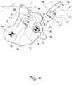
Fig. 2 im Crashfall a) während der crashbedingten Verstellung des Crashelements vom Ausgangszustand in Richtung des Crashzustands und b) nach crashbedingter Verrastung des Crashelements im Crashzustand, - Fig. 4
- die Anordnung gemäß
Fig. 2 während der Rückstellung des crashbedingt betätigten Betätigungshebels und - Fig. 5
- die Anordnung gemäß
Fig. 2 in einer weiteren Ausführungsform im Normalfall. - Es darf vorab darauf hingewiesen werden, dass in der Zeichnung nur die Komponenten eines vorschlagsgemäßen Kraftfahrzeugschlosses 1 dargestellt sind, die für die Erläuterung der Lehre erforderlich sind. Beispielsweise ist auf die Darstellung einer Schlossmechanik verzichtet worden, die die Einstellung unterschiedlicher Verriegelungszustände wie "verriegelt" und "entriegelt" bereitstellt. Auch auf die Darstellung eines Türinnengriffs ist vorliegend verzichtet worden. Alle folgenden Ausführungen gelten für Kraftfahrzeugschlösser mit derartigen, hier nicht dargestellten Komponenten entsprechend.
-
Fig. 1 zeigt, dass das Kraftfahrzeugschloss 1 ein Schlossgehäuse 1a und darin die Schließelemente Schlossfalle 2 und Sperrklinke 3 aufweist, die in an sich üblicher Weise miteinander wechselwirken. Die Schlossfalle 2 ist in die inFig. 1 gezeigte Hauptschließstellung bringbar, in der sie von der Sperrklinke 3 gehalten wird. Dabei steht die Schlossfalle 2 in haltendem Eingriff mit einem Schließteil 4, das hier und vorzugsweise als Schließbolzen ausgestaltet ist. Die Sperrklinke 3 lässt sich hier um eine Sperrklinkenachse 3a, inFig. 1 im Uhrzeigersinn, schwenken, so dass die Schlossfalle 2 freigegeben wird und um eine Schlossfallenachse 2a, inFig. 1 im Gegenuhrzeigersinn, in Öffnungsrichtung schwenken kann. Dann ist das Schließteil 4 freigegeben und die dem Kraftfahrzeugschloss 1 zugeordnete Kraftfahrzeugtür o. dgl. kann geöffnet werden. - Das vorschlagsgemäße Kraftfahrzeugschloss 1 weist mindestens einen um eine Betätigungshebelachse 5a schwenkbaren Betätigungshebel 5 auf, durch dessen Betätigung aus einer Ausgangsstellung heraus in eine Betätigungsstellung die Sperrklinke 3 aushebbar ist. Die Ausgangsstellung ist in
Fig. 2a gezeigt, während die Betätigungsstellung inFig. 2b gezeigt ist. Die Aushebbarkeit der Sperrklinke 3 hängt je nach Ausgestaltung des Kraftfahrzeugschlosses 1 nicht nur von der Betätigung des Betätigungshebels 5, sondern auch von dem Verriegelungszustand einer eventuell vorgesehenen Schlossmechanik ab. Dies spielt für die vorschlagsgemäße Lösung aber keine Rolle. - Der Betätigungshebel 5 ist hier und vorzugsweise mit einem Türgriff 8, insbesondere einem Türaußengriff, gekoppelt. Grundsätzlich kann es sich bei dem Türgriff aber auch um einen Türinnengriff oder um einen sonstigen Türgriff handeln. In den
Fig. 2 bis 5 ist der Antriebsstrang zum Türgriff mit dem Bezugszeichen A angedeutet, während der Antriebsstrang zu der Sperrklinke 3 mit dem Bezugszeichen B angedeutet ist. - Ferner ist das Kraftfahrzeugschloss 1 mit einem Crashelement 6 ausgestattet, das in noch zu erläuternder Weise aus einem Normalzustand heraus in einen Crashzustand verstellbar ist. Der Normalzustand des Crashelements 6 ist in
Fig. 2a gezeigt, während der Crashzustand des Crashelements 6 inFig. 3a gezeigt ist. - Im Crashzustand übt das Crashelement 6 je nach Ausgestaltung einen unterschiedlichen Einfluss auf das Kraftfahrzeugschloss 1 im Übrigen aus. Bei der in den
Fig. 2 bis 4 gezeigten Ausgestaltung blockiert das im Crashzustand befindliche Crashelement 6 den Betätigungshebel 5 in einer Blockierstellung, wie inFig. 3b gezeigt ist. Bei der Ausgestaltung gemäßFig. 5 ist es dagegen vorgesehen, dass das im Crashzustand befindliche Crashelement 6 den Betätigungshebel 5 von der Sperrklinke 3 entkuppelt, so dass der Betätigungshebel 5 bei im Crashzustand befindlichem Crashelement 6 freiläuft. - Bei beiden Ausführungsformen ist es so, dass das Crashelement 6 bei einer Betätigung des Betätigungshebels 5 mit einer übermäßigen Betätigungsgeschwindigkeit im Crashzustand verrastet. Der verrastete Crashzustand ist für das erstgenannte Ausführungsbeispiel in
Fig. 3b gezeigt. Der Begriff "verrastet" bedeutet hier, dass das Crashelement 6 zunächst einmal im Crashzustand verbleibt, selbst wenn die Betätigung des Betätigungshebels 5 mit übermäßiger Betätigungsgeschwindigkeit wegfällt. Erst wenn die Verrastung aufgehoben wird, kann das Crashelement 6 wieder in den Normalzustand fallen. - Wesentlich ist nun, dass bei im Crashzustand verrasteten Crashelement 6 eine Rückstellung des Betätigungshebels 5 in die Ausgangsstellung die Aufhebung der Verrastung und die Verstellung des Crashelements 6 in den Normalzustand bewirkt. Die Rückstellung des Betätigungshebels 5 ist in der Zeichnung durch den Übergang von
Fig. 4 aufFig. 2a gezeigt. Diese selbsttätige Aufhebung der Verrastung ist insbesondere vorteilhaft, als der Bediener die Funktion des Crashelements 6 nicht wahrnimmt, so dass die Bedienbarkeit auch im Crashfall vollumfänglich gegeben ist. - Der Betätigungshebel 5 ist hier und vorzugsweise mittels eines Federelements 7 in seine Ausgangsstellung federvorgespannt, so dass die Rückstellung des Betätigungshebels 5 stets selbsttätig vonstatten geht.
- Grundsätzlich kann es vorgesehen sein, dass bei im Crashzustand verrastetem Crashelement 6 erst die bezogen auf den Bewegungsbereich zwischen Ausgangsstellung und Betätigungsstellung mindestens 80-prozentige Rückstellung des Betätigungshebels 5, hier und vorzugsweise erst die vollständige Rückstellung des Betätigungshebels 5, in die Ausgangsstellung die Aufhebung der Verrastung und die Verstellung des Crashelements 6 in den Normalzustand bewirkt. Dies bedeutet, dass nach einer crashbedingten Betätigung des Betätigungshebels 5 eine Rückstellung des Betätigungshebels 5 um einen gewissen Weg vorgesehen ist, ohne dass die Verrastung aufgehoben wird. Kommt es während dieses Rückstellens also zu einer erneuten, crashbedingten Betätigung, so befindet sich das Crashelement 6 immer noch im Crashzustand, so dass der Betätigungshebel 5 immer noch blockiert wird (
Fig. 2 bis 4 ) oder frei läuft (Fig. 5 ). Hier und vorzugsweise ist es so, dass bei im Crashzustand verrastetem Crashelement 6 erst die vollständige Rückstellung des Betätigungshebels 5 in die Ausgangsstellung die Aufhebung der Verrastung und die Verstellung des Crashelements 6 in den Normalzustand bewirkt. - Für die vorschlagsgemäße Verstellung des Crashelements 6 in Abhängigkeit von der Betätigungsgeschwindigkeit des Betätigungshebels 5 sind verschiedene Realisierungsmöglichkeiten denkbar. Bei dem dargestellten und insoweit bevorzugten Ausführungsbeispiel ist es so, dass eine Betätigung des Betätigungshebels 5 mit einer Betätigungsgeschwindigkeit oberhalb einer Grenzbetätigungsgeschwindigkeit durch die Massenträgheit des Crashelements 6 eine Verstellung des Crashelements 6 in den Crashzustand bewirkt. Dies zeigt der Übergang von
Fig. 2a aufFig. 3a . Dabei ist zunächst einmal festzustellen, dass das Crashelement 6 in den Normalzustand federvorgespannt ist. Hierfür ist dem Crashelement 6 ein erstes Federelement 9 zugeordnet. - Die Verstellbarkeit des Crashelements 6 zwischen dem Ausgangszustand (
Fig. 2a ) und dem Crashzustand (Fig. 3b ) ergibt sich hier und vorzugsweise durch eine spezielle Lagerung des Crashelements 6. Zunächst einmal ist es vorzugsweise so, dass das Crashelement 6 mittels einer Crashelementlagerung 10 auf dem Betätigungshebel 5 um eine Crashelementachse 6a, die weiter vorzugsweise entfernt von der Betätigungshebelachse 5a angeordnet ist, schwenkbar gelagert ist. Hervorzuheben dabei ist, dass die Crashelementachse 6a auf dem Betätigungshebel 5 vorzugsweise verlagerbar ist, wobei die Verstellung des Crashelements 6 zwischen dem Normalzustand und dem Crashzustand auf eine Verlagerung der Crashelementachse 6a auf dem Betätigungshebel 5 zurückgeht. Bei dieser Verlagerbarkeit der Crashelementachse 6a auf dem Betätigungshebel 5 handelt es sich in besonders bevorzugter Ausgestaltung um eine lineare Verlagerbarkeit. Im einfachsten Falle ist es so, dass die Crashelementlagerung 10 auf den Eingriff eines Lagerzapfens 11 mit einem Langloch 12 zurückgeht. Hier und vorzugsweise ist der Lagerzapfen 11 am Betätigungshebel 5 angeordnet, während das Langloch 12 am Crashelement 6 angeordnet ist. - Bei den dargestellten und insoweit bevorzugten Ausführungsbeispielen ist das Crashelement 6, hier und vorzugsweise gegenüber dem Betätigungshebel 5, aus einer Ausgangsstellung heraus (
Fig. 2a ) um die Crashelementachse 6a schwenkbar, wobei das Crashelement 6 in die Ausgangsstellung federvorgespannt ist. Hierfür ist das Crashelement mit einem zweiten Federelement 13 ausgestattet. - Vorzugsweise wird mit der Verstellung des Crashelements 6 zwischen dem Normalzustand und dem Crashzustand eine schaltbare Kupplung 14 geschaltet. Die Kupplung 14 ist zwischen dem Betätigungshebel 5 und dem Crashelement 6 vorgesehen. Sie wird in Abhängigkeit vom Zustand des Crashelements 6 in einen gekuppelten Zustand oder in einen entkuppelten Zustand geschaltet. Hier und vorzugsweise handelt es sich bei der Kupplung 14 um eine Kulissenkupplung, wie weiter unten noch erläutert wird.
- Bei dem in den
Fig. 2 bis 4 gezeigten Ausführungsbeispiel ist die Anordnung so getroffen, dass die Kupplung 14 im Normalzustand des Crashelements 6 im entkuppelten Zustand steht und im Crashzustand des Crashelements 6 im gekuppelten Zustand steht. Dies ist bei dem inFig. 5 gezeigten Ausführungsbeispiel andersherum vorgesehen. - Im Einzelnen weist die Kupplung 14 vorzugsweise zwei von dem Betätigungshebel 5 einerseits und von dem Crashelement 6 andererseits bereitgestellte Kupplungselemente 15, 16 auf, die in Abhängigkeit vom Kupplungszustand miteinander in Eingriff stehen. Dabei ist eines der Kupplungselemente 15, 16, hier das vom Betätigungshebel 5 bereitgestellte Kupplungselement 15, als Kulisse und das andere der Kupplungselemente 15, 16, hier das vom Crashelement 6 bereitgestellte Kupplungselement 16, als Kulissenstein, der in der Kulisse läuft, ausgebildet. Eine solche Kulissenkupplung ist eine besonders robuste und kostengünstige Möglichkeit für die Realisierung der Kupplung 14.
- Es ergibt sich aus einer Zusammenschau von
Fig. 2a und Fig. 2b , dass bei im Normalzustand befindlichem Crashelement 6 die Kupplung 14 dort im entkuppelten Zustand steht, so dass der Betätigungshebel 5 und das Crashelement 6 über einen Bewegungsbereich frei gegeneinander verschwenkbar sind. Bei im Crashzustand befindlichem Crashelement 6, also bei im gekuppelten Zustand befindlicher Kupplung 14, stellt die Kupplung dann eine antriebstechnische Kopplung zwischen dem Crashelement 6 zwischen dem Betätigungshebel 5 und dem Crashelement 6 bezogen auf eine Schwenkbewegung des Crashelements 6 um die Crashelementachse 6a her. Dies ist speziell inFig. 3b gezeigt. Hier wird deutlich, dass das als Kulisse ausgestaltete Kupplungselement 15 einen Mitnehmer-Kulissenabschnitt 17 aufweist, der im gekuppelten Zustand in Eingriff mit dem als Kulissenstein ausgestalteten Kupplungselement 16 steht. Im entkuppelten Zustand dagegen läuft das als Kulissenstein ausgestaltete Kupplungselement 16 in einem Freilauf-Kulissenabschnitt 18, ohne dass über die Kupplung 14 eine Wechselwirkung zwischen dem Betätigungshebel 5 und dem Crashelement 6 vorliegt. - Bei dem in den
Fig. 2 bis 4 gezeigten Ausführungsbeispiel ist ein relativ zu dem Betätigungshebel 5 ortsfester Blockieranschlag 19 vorgesehen, mit dem das Crashelement 6 bei einer Betätigung des Betätigungshebels 5 in Anlage kommt. Dies ist inFig. 2b undFig. 3b gezeigt. Bei einer Betätigung des Betätigungshebels 5 in denFig. 2 ,3 um die Betätigungshebelachse 5a im Gegenuhrzeigersinn bedeutet dies, dass das Crashelement 6 um die Crashelementachse 6a im Uhrzeigersinn schwenkt, sofern dies durch die Kupplung 14 nicht verhindert wird. - Im Ergebnis ist es bei dem in den
Fig. 2 bis 4 gezeigten Ausführungsbeispiel so, dass bei im Crashzustand befindlichem Crashelement 6 eine Betätigung des Betätigungshebels 5 über die Kupplung 14, das Crashelement 6 und den Blockieranschlag 19 blockiert wird, wie inFig. 3b gezeigt ist. Bei im Normalzustand befindlichem Crashelement 6 ist es dagegen vorzugsweise vorgesehen, dass eine Betätigung des Betätigungshebels 5 mit einer Ausgleichsbewegung des Crashelements 6 gegenüber dem Betätigungshebel 5 einhergeht. Die Ausgleichsbewegung ergibt sich durch den Übergang vonFig. 2a aufFig. 2b . - Während das in den
Fig. 2 bis 4 dargestellte Ausführungsbeispiel darauf gerichtet ist, dass der Betätigungshebel 5 bei im Crashzustand befindlichem Crashelement 6 blockiert ist, kommt es bei dem inFig. 5 dargestellten Ausführungsbeispiel bei im Crashzustand befindlichem Crashelement 6 zur Entkupplung des Betätigungshebels 5 von der Sperrklinke 3, so dass der Betätigungshebel 5 bei im Crashzustand befindlichem Crashelement 6 einen Freilauf durchführt. - Im Einzelnen ist es bei dem in
Fig. 5 dargestellten Ausführungsbeispiel vorgesehen, dass bei im Crashzustand befindlichem Crashelement 6 der Betätigungshebel 5 mittels der Kupplung 14 antriebstechnisch von der Sperrklinke 3 getrennt ist. Bei im Normalzustand befindlichem Crashelement 6 ist es dagegen vorzugsweise vorgesehen, dass der Betätigungshebel 5 mittels der Kupplung 14 antriebstechnisch mit der Sperrklinke 3 koppelbar ist. Dies wird bei dem inFig. 5 dargestellten Ausführungsbeispiel ausgehend von dem in denFig. 2 bis 4 dargestellten Ausführungsbeispiel durch eine Umgestaltung des als Kulisse ausgestalteten Kupplungselements 15 erreicht. Ferner ist der Blockieranschlag 19 nunmehr in einer Längsführung 20 geführt, die vorzugsweise gehäusefest angeordnet ist. Bei im Normalzustand befindlichem Crashelement 6 sorgt der Mitnehmer-Kulissenabschnitt 17 für die Mitnahme des als Kulissenstein ausgestalteten Kupplungselements 16, so dass der Blockieranschlag 19 in der Längsführung 20 läuft. Dadurch, dass der zu der Sperrklinke 3 verlaufende Antriebsstrang B nunmehr mit dem Blockieranschlag 19 gekoppelt ist, lässt sich so ein Ausheben der Sperrklinke 3 bewerkstelligen. Im Crashfall dagegen, wird das Crashelement 6, wie im Zusammenhang mit denFig. 2 bis 4 erläutert, in den Crashzustand überführt, so dass das als Kulissenstein ausgestaltete Kupplungselement 16 in dem Freilauf-Kulissenabschnitt 18 läuft. Bei im Crashzustand befindlichem Crashelement 6 läuft der Betätigungshebel 5 also frei. Solange der Betätigungshebel 5 noch nicht in seine Ausgangsstellung rückgestellt ist, ist das Crashelement 6 durch die Wechselwirkung des Freilauf-Kulissenabschnitts 18 mit dem als Kulissenstein ausgestalteten Kupplungselement 16 im Crashzustand in obigem Sinne verrastet. - Bei beiden dargestellten Ausführungsbeispielen ist es vorgesehen, dass die Verrastung des Crashelements 6 im Crashzustand auf eine Verrastung der Kupplung 14 zurückgeht. Im Einzelnen sind die Kupplungselemente 15, 16 der Kupplung 14 bei im Crashzustand befindlichem Crashelement 6 miteinander verrastet. Vorzugsweise weist hierfür eines der Kupplungselemente 15, hier das als Kulisse ausgestaltete Kupplungselement 15, einen Hinterschnitt 21 auf, den das andere der Kupplungselemente 15, 16, hier das als Kulissenstein ausgestaltete Kupplungselement 16, zur Verrastung der beiden Kupplungselemente 15, 16 miteinander hintergreift. Bei dem in den
Fig. 2 bis 4 dargestellten Ausführungsbeispiel findet sich der Hinterschnitt 21 an dem Mitnehmer-Kulissenabschnitt 17, während bei dem inFig. 5 dargestellten Ausführungsbeispiel der Hinterschnitt 21 von dem Freilauf-Kulissenabschnitt 18 bereitgestellt wird. - Es darf schließlich noch darauf hingewiesen werden, dass vorschlagsgemäß das Crashelement 6 durch eine übermäßige Betätigungsgeschwindigkeit des Betätigungshebels 5 in den Crashzustand verstellt wird. Zusätzlich kann es aber auch vorgesehen sein, dass die Verstellung des Crashelements 6 in den Crashzustand durch eine auf das Kraftfahrzeugschloss 1 wirkende, im Crashfall auftretende Beschleunigung bewirkt wird. Für den Fall, dass das Kraftfahrzeugschloss 1 einer Seitentür eines Kraftfahrzeugs zugeordnet ist, kann es beispielsweise vorgesehen sein, dass die Crashelementlagerung 10 so ausgerichtet ist, dass ein Seitenaufprall auf die Seitentür zu einer trägheitsbedingten Verstellung des Crashelements 6 von dem Normalzustand in den Crashzustand führt. Hierbei handelt es sich um eine Relativverstellung des Crashelements 6 relativ zu dem Betätigungshebel 5. Durch diese konstruktive Auslegung wird die Crashsicherheit des Kraftfahrzeugschlosses 1 weiter erhöht.
Claims (14)
- Kraftfahrzeugschloss mit den Schließelementen Schlossfalle (2) und Sperrklinke (3), wobei das Kraftfahrzeugschloss (1) einen um eine Betätigungshebelachse (5a) schwenkbaren Betätigungshebel (5) aufweist, durch dessen Betätigung aus einer Ausgangsstellung heraus in eine Betätigungsstellung die Sperrklinke (3) aushebbar ist, wobei das Kraftfahrzeugschloss (1) ein Crashelement (6) aufweist, das aus einem Normalzustand heraus in einen Crashzustand verstellbar ist, in dem das Crashelement (6) den Betätigungshebel (5) in einer Blockierstellung blockiert oder von der Sperrklinke (3) entkuppelt, wobei das Crashelement (6) derart mit dem Betätigungshebel (5) gekoppelt ist, dass das Crashelement (6) bei einer Betätigung des Betätigungshebels (5) mit einer Betätigungsgeschwindigkeit oberhalb einer Grenzbetätigungsgeschwindigkeit im Crashzustand verrastet,
dadurch gekennzeichnet,
dass bei im Crashzustand verrasteten Crashelement (6) eine Rückstellung des Betätigungshebels (5) in die Ausgangsstellung die Aufhebung der Verrastung und die Verstellung des Crashelements (6) in den Normalzustand bewirkt. - Kraftfahrzeugschloss nach Anspruch 1, dadurch gekennzeichnet, dass bei im Crashzustand verrastetem Crashelement (6) erst die bezogen auf den Bewegungsbereich zwischen Ausgangsstellung und Betätigungsstellung mindestens 80-prozentige Rückstellung des Betätigungshebels (5), vorzugsweise erst die vollständige Rückstellung des Betätigungshebels (5), in die Ausgangsstellung die Aufhebung der Verrastung und die Verstellung des Crashelements (6) in den Normalzustand bewirkt.
- Kraftfahrzeugschloss nach Anspruch 1 oder 2, dadurch gekennzeichnet, dass eine Betätigung des Betätigungshebels (5) mit einer Betätigungsgeschwindigkeit oberhalb der Grenzbetätigungsgeschwindigkeit durch die Massenträgheit des Crashelements (6) eine Verstellung des Crashelements (6) in den Crashzustand bewirkt.
- Kraftfahrzeugschloss nach einem der vorhergehenden Ansprüche, dadurch gekennzeichnet, dass das Crashelement (6) in den Normalzustand federvorgespannt ist.
- Kraftfahrzeugschloss nach einem der vorhergehenden Ansprüche, dadurch gekennzeichnet, dass das Crashelement (6) mittels einer Crashelementlagerung (10) auf dem Betätigungshebel (5) um eine Crashelementachse (6a), die vorzugsweise entfernt von der Betätigungshebelachse (5a) angeordnet ist, schwenkbar gelagert ist, vorzugsweise, dass die Crashelementachse (6a) auf dem Betätigungshebel (5) verlagerbar ist und dass die Verstellung des Crashelements (6) zwischen dem Normalzustand und dem Crashzustand auf eine Verlagerung der Crashelementachse (6a) auf dem Betätigungshebel (5) zurückgeht.
- Kraftfahrzeugschloss nach einem der vorhergehenden Ansprüche, dadurch gekennzeichnet, dass das Crashelement (6) aus einer Ausgangsstellung heraus um die Crashelementachse (6a) schwenkbar ist und dass das Crashelement (6) in die Ausgangsstellung federvorgespannt ist.
- Kraftfahrzeugschloss nach einem der vorhergehenden Ansprüche, dadurch gekennzeichnet, dass eine schaltbare Kupplung (14), insbesondere eine Kulissenkupplung, zwischen dem Betätigungshebel (5) und dem Crashelement (6) vorgesehen ist, die in Abhängigkeit vom Zustand des Crashelements (6) in einen gekuppelten Zustand oder in einen entkuppelten Zustand geschaltet ist.
- Kraftfahrzeugschloss nach einem der vorhergehenden Ansprüche, dadurch gekennzeichnet, dass die Kupplung (14) zwei von dem Betätigungshebel (5) einerseits und von dem Crashelement (6) andererseits bereitgestellte Kupplungselemente (15, 16) aufweist, die in Abhängigkeit vom Kupplungszustand miteinander in Eingriff stehen, vorzugsweise, dass eines der Kupplungselemente (15, 16) als Kulisse und das andere der Kupplungselemente (15, 16) als Kulissenstein ausgebildet sind.
- Kraftfahrzeugschloss nach einem der vorhergehenden Ansprüche, dadurch gekennzeichnet, dass die Kupplung (14) im gekuppelten Zustand eine antriebstechnische Kopplung zwischen dem Betätigungshebel (5) und dem Crashelement (6) bezogen auf eine Schwenkbewegung des Crashelements (6) um die Crashelementachse (6a) herstellt.
- Kraftfahrzeugschloss nach einem der vorhergehenden Ansprüche, dadurch gekennzeichnet, dass ein relativ zu dem Betätigungshebel (5) ortsfester Blockieranschlag (19) vorgesehen ist, mit dem das Crashelement (6) bei einer Betätigung des Betätigungshebels (5) in Anlage kommt.
- Kraftfahrzeugschloss nach einem der vorhergehenden Ansprüche, dadurch gekennzeichnet, dass bei im Crashzustand befindlichem Crashelement (6) eine Betätigung des Betätigungshebels (5) über die Kupplung (14), das Crashelement (6) und den Blockieranschlag (19) blockiert wird, und/oder, dass bei im Normalzustand befindlichem Crashelement (6) eine Betätigung des Betätigungshebels (5) mit einer Ausgleichsbewegung des Crashelements (6) gegenüber dem Betätigungshebel einhergeht.
- Kraftfahrzeugschloss nach einem der vorhergehenden Ansprüche, dadurch gekennzeichnet, dass bei im Crashzustand befindlichem Crashelement (6) der Betätigungshebel (5) mittels der Kupplung (14) antriebstechnisch von der Sperrklinke (3) getrennt ist, und/oder, dass bei im Normalzustand befindlichem Crashelement (6) der Betätigungshebel (5) mittels der Kupplung (14) antriebstechnisch mit der Sperrklinke (3) koppelbar ist.
- Kraftfahrzeugschloss nach einem der vorhergehenden Ansprüche, dadurch gekennzeichnet, dass die Verrastung des Crashelements (6) im Crashzustand auf eine Verrastung der Kupplung (14) zurückgeht und dass bei im Crashzustand befindlichem Crashelement (6) die Kupplungelemente (15, 16) der Kupplung (14) miteinander verrastet sind, vorzugsweise, dass eines der Kupplungselemente (15, 16) einen Hinterschnitt (21) aufweist, den das andere der Kupplungselemente (15, 16) zur Verrastung der beiden Kupplungselemente (15, 16) miteinander hintergreift.
- Kraftfahrzeugschloss nach einem der vorhergehenden Ansprüche, dadurch gekennzeichnet, das Crashelement (6) durch eine auf das Kraftfahrzeugschloss (1) wirkende, im Crashfall auftretende Beschleunigung in den Crashzustand verstellbar ist.
Applications Claiming Priority (1)
| Application Number | Priority Date | Filing Date | Title |
|---|---|---|---|
| DE102017113880.3A DE102017113880A1 (de) | 2017-06-22 | 2017-06-22 | Kraftfahrzeugschloss |
Publications (2)
| Publication Number | Publication Date |
|---|---|
| EP3418478A1 EP3418478A1 (de) | 2018-12-26 |
| EP3418478B1 true EP3418478B1 (de) | 2022-04-20 |
Family
ID=62630987
Family Applications (1)
| Application Number | Title | Priority Date | Filing Date |
|---|---|---|---|
| EP18177484.5A Active EP3418478B1 (de) | 2017-06-22 | 2018-06-13 | Kraftfahrzeugschloss |
Country Status (4)
| Country | Link |
|---|---|
| US (1) | US11608660B2 (de) |
| EP (1) | EP3418478B1 (de) |
| CN (1) | CN109113460B (de) |
| DE (1) | DE102017113880A1 (de) |
Families Citing this family (4)
| Publication number | Priority date | Publication date | Assignee | Title |
|---|---|---|---|---|
| JP7294044B2 (ja) * | 2019-10-08 | 2023-06-20 | 三井金属アクト株式会社 | ドアラッチ装置 |
| CN111232180B (zh) * | 2020-02-26 | 2021-10-19 | 中国商用飞机有限责任公司 | 飞机舱门阵风锁装置 |
| JP7711601B2 (ja) * | 2022-02-03 | 2025-07-23 | 日産自動車株式会社 | ドアラッチ装置 |
| JP7834576B2 (ja) * | 2022-05-19 | 2026-03-24 | 株式会社ハイレックスアクト | ドアラッチ装置 |
Family Cites Families (67)
| Publication number | Priority date | Publication date | Assignee | Title |
|---|---|---|---|---|
| US703962A (en) | 1901-03-09 | 1902-07-01 | Internat Mfg Company | Lock. |
| US846129A (en) | 1906-04-25 | 1907-03-05 | Clyde S Morse | Sliding-door fastener. |
| US2793898A (en) | 1949-07-02 | 1957-05-28 | Roethel Engineering Corp | Door lock |
| US2832626A (en) | 1955-04-22 | 1958-04-29 | Gen Motors Corp | Door latch-adjustable linkage for push button |
| US3848909A (en) | 1973-06-01 | 1974-11-19 | Gen Motors Corp | Closure latch assembly |
| US4441345A (en) | 1982-01-19 | 1984-04-10 | Guarr David A | Lock device for vehicle hoods |
| US4911489A (en) | 1989-02-01 | 1990-03-27 | A. L. Hansen Manufacturing Company | T-handle latch |
| DE4102279C1 (de) | 1991-01-26 | 1992-03-05 | Mercedes-Benz Aktiengesellschaft, 7000 Stuttgart, De | |
| DE19511651C5 (de) | 1994-04-15 | 2008-07-10 | Volkswagen Ag | Sicherung für eine Fahrzeugtür gegen ungewolltes Öffnen beim Auftreten stoßbedingter seitlicher Massenträgheitskräfte |
| DE19624640C1 (de) | 1996-06-20 | 1998-01-08 | Kiekert Ag | Kraftfahrzeugtürverschluß mit Drehfalle, Sperrklinke und Blockiervorrichtung |
| US5967572A (en) | 1996-08-08 | 1999-10-19 | Volkswagen Ag | Lock control arrangement for a vehicle door |
| DE19842358C2 (de) | 1998-09-16 | 2001-02-22 | Kiekert Ag | Kraftfahrzeugtürverschluß mit Schließelementen |
| DE19860824A1 (de) | 1998-12-30 | 2000-07-06 | Volkswagen Ag | Toleranzausgleich für eine kraftübertragende Verbindung zwischen einem Handgriff und einem Schloßauslösehebel |
| DE19919765A1 (de) | 1999-04-29 | 2000-11-09 | Bosch Gmbh Robert | Kraftfahrzeug-Türschloß o.dgl. mit elektrischer Öffnungshilfe und Schließhilfe |
| US6543820B2 (en) | 2000-12-18 | 2003-04-08 | Gsle Development Corporation | Latching device and method |
| US7175211B2 (en) | 2002-02-25 | 2007-02-13 | Intier Automotive Closures Inc. | Latch with shipping condition |
| US8056944B2 (en) | 2002-06-13 | 2011-11-15 | Ford Global Technologies | Latch assembly for a vehicle door |
| GB0214817D0 (en) | 2002-06-27 | 2002-08-07 | Arvinmeritor Light Vehicle Sys | Door latch mechanism |
| CA2401397A1 (en) | 2002-07-26 | 2004-01-26 | Intier Automotive Closures Inc. | Inertia catch for a vehicle latch |
| DE10337392A1 (de) | 2003-08-13 | 2005-03-17 | Kiekert Ag | Kombiniertes Bowdenzug-/Hebelaggregat |
| DE10345104A1 (de) | 2003-09-26 | 2005-04-21 | Kiekert Ag | Kraftfahrzeugtürverschluss |
| DE102004014550A1 (de) | 2004-03-23 | 2005-10-13 | Brose Schließsysteme GmbH & Co.KG | Kraftfahrzeugschloß |
| US8408612B2 (en) | 2004-04-30 | 2013-04-02 | Intier Automotive Closures Inc | Rotary locking mechanism for outside vehicle door handle |
| US7325874B2 (en) | 2004-10-14 | 2008-02-05 | Johnson Controls Technology Company | Latch mechanism |
| CN101133224B (zh) | 2005-03-04 | 2011-05-04 | 丰田纺织株式会社 | 锁定装置 |
| GB0509350D0 (en) | 2005-05-07 | 2005-06-15 | Arvinmeritor Light Vehicle Sys | Latch |
| US7703828B2 (en) | 2007-07-25 | 2010-04-27 | Lear Corporation | Latch system for releasably securing a seat to a floor |
| DE102008018500A1 (de) | 2007-09-21 | 2009-04-02 | BROSE SCHLIEßSYSTEME GMBH & CO. KG | Kraftfahrzeugschloß |
| DE202008007673U1 (de) * | 2008-06-09 | 2009-10-22 | BROSE SCHLIEßSYSTEME GMBH & CO. KG | Kraftfahrzeugschloß |
| KR100957103B1 (ko) | 2008-06-30 | 2010-05-13 | 현대자동차주식회사 | 차량용 도어래치장치 |
| DE202008012484U1 (de) | 2008-09-21 | 2010-02-18 | BROSE SCHLIEßSYSTEME GMBH & CO. KG | Kraftfahrzeugschloß |
| DE102008051832A1 (de) | 2008-10-17 | 2010-04-22 | Johnson Controls Gmbh | Verriegelungselement für einen Fahrzeugsitz |
| US8353542B2 (en) | 2009-05-05 | 2013-01-15 | Magna Closures S.P.A. | Closure latch with inertia member |
| DE202009009061U1 (de) | 2009-06-30 | 2010-12-09 | Kiekert Ag | Kraftfahrzeugtürschloss |
| DE202009009060U1 (de) | 2009-06-30 | 2010-12-09 | Kiekert Ag | Kraftfahrzeugtürschloss |
| JP5285524B2 (ja) | 2009-07-22 | 2013-09-11 | 株式会社アンセイ | 車両用ドアロック装置 |
| DE102009045843A1 (de) * | 2009-10-20 | 2011-04-21 | Huf Hülsbeck & Fürst Gmbh & Co. Kg | Griffvorrichtung |
| DE202009017667U1 (de) | 2009-12-26 | 2011-05-05 | BROSE SCHLIEßSYSTEME GMBH & CO. KG | Kraftfahrzeugschlossanordnung |
| DE102010010833B4 (de) | 2010-03-10 | 2023-12-07 | Kiekert Aktiengesellschaft | Kraftfahrzeugtürverschluss |
| US20110252844A1 (en) | 2010-04-19 | 2011-10-20 | Shoemaker Rodney T | Overhead door lock with automated locking and integrated detection systems |
| DE102010049393A1 (de) | 2010-10-26 | 2012-04-26 | Kiekert Ag | Kraftfahrzeugtürverschluss |
| DE102011010815A1 (de) | 2011-02-09 | 2012-08-09 | Kiekert Ag | Kraftfahrzeugtürverschluss |
| DE202011003497U1 (de) | 2011-03-04 | 2012-06-05 | Kiekert Ag | Kraftfahrzeugtürschloss |
| US9410345B2 (en) | 2011-03-16 | 2016-08-09 | Ansei Corporation | Vehicle door lock device |
| DE202011005608U1 (de) | 2011-04-27 | 2013-06-18 | BROSE SCHLIEßSYSTEME GMBH & CO. KG | Kraftfahrzeugschloss |
| JP5418549B2 (ja) * | 2011-07-06 | 2014-02-19 | アイシン精機株式会社 | 車両のドアアウタハンドル装置 |
| US9631404B2 (en) | 2011-09-27 | 2017-04-25 | Ansei Corporation | Vehicle door lock apparatus |
| US8950810B2 (en) | 2011-11-18 | 2015-02-10 | Toyo Seat Usa Corp. | Latch mechanism for automotive seat assembly |
| KR101806564B1 (ko) | 2011-12-12 | 2017-12-08 | 현대자동차주식회사 | 차량의 도어래치장치 |
| KR101806565B1 (ko) | 2011-12-13 | 2017-12-08 | 현대자동차주식회사 | 차량의 도어래치장치 |
| DE102012102724A1 (de) | 2012-03-29 | 2013-10-02 | Huf Hülsbeck & Fürst Gmbh & Co. Kg | Kraftfahrzeugtürverschluss |
| US9322198B2 (en) | 2012-05-25 | 2016-04-26 | Nissan North America, Inc. | Vehicle door latch mechanism |
| DE202012007312U1 (de) * | 2012-07-31 | 2013-11-04 | BROSE SCHLIEßSYSTEME GMBH & CO. KG | Kraftfahrzeugschlossanordnung |
| US9115514B2 (en) | 2012-10-04 | 2015-08-25 | Ford Global Technologies, Llc | Mechanically initiated speed-based latch device |
| DE102013211050A1 (de) * | 2013-03-06 | 2014-09-11 | Kiekert Ag | Schloss für ein Kraftfahrzeug |
| US9732544B2 (en) * | 2013-03-25 | 2017-08-15 | Brose Schliesssysteme Gmbh & Co. Kg | Motor vehicle lock |
| US9874046B2 (en) | 2013-03-25 | 2018-01-23 | Brose Schliesssysteme Gmbh & Co. Kommanditgesellschaft | Motor vehicle lock |
| US9376842B2 (en) | 2013-03-25 | 2016-06-28 | Brose Schliesssysteme Gmbh & Co. Kg | Motor vehicle lock |
| US9366063B2 (en) | 2013-03-25 | 2016-06-14 | Brose Schliesssysteme Gmbh & Co. Kg | Motor vehicle lock |
| US20140284942A1 (en) | 2013-03-25 | 2014-09-25 | Brose Schliesssysteme Gmbh & Co. Kg | Motor vehicle lock |
| DE202013104118U1 (de) * | 2013-09-10 | 2014-12-15 | BROSE SCHLIEßSYSTEME GMBH & CO. KG | Kraftfahrzeugschloss |
| US20150115628A1 (en) | 2013-10-28 | 2015-04-30 | Brose Schliesssysteme Gmbh & Co. Kg | Lock component |
| DE102014004552A1 (de) * | 2014-03-31 | 2015-10-01 | Kiekert Aktiengesellschaft | Betätigungseinrichtung für ein Kraftfahrzeugschloss |
| DE102015112500A1 (de) | 2014-09-30 | 2016-03-31 | BROSE SCHLIEßSYSTEME GMBH & CO. KG | Kraftfahrzeugschloss |
| CN104847186B (zh) | 2015-05-20 | 2018-08-21 | 浙江吉利汽车研究院有限公司 | 一种汽车车门锁的防侧碰开启装置 |
| DE102015114634A1 (de) * | 2015-09-02 | 2017-03-02 | Kiekert Ag | Kraftfahrzeugtürverschluss |
| DE102017102899A1 (de) * | 2017-02-14 | 2018-08-16 | Kiekert Ag | Kraftfahrzeugtürschloss |
-
2017
- 2017-06-22 DE DE102017113880.3A patent/DE102017113880A1/de not_active Withdrawn
-
2018
- 2018-06-13 EP EP18177484.5A patent/EP3418478B1/de active Active
- 2018-06-22 CN CN201810651801.2A patent/CN109113460B/zh active Active
- 2018-06-22 US US16/015,414 patent/US11608660B2/en active Active
Also Published As
| Publication number | Publication date |
|---|---|
| CN109113460A (zh) | 2019-01-01 |
| US20180371803A1 (en) | 2018-12-27 |
| DE102017113880A1 (de) | 2018-12-27 |
| CN109113460B (zh) | 2021-06-11 |
| EP3418478A1 (de) | 2018-12-26 |
| US11608660B2 (en) | 2023-03-21 |
Similar Documents
| Publication | Publication Date | Title |
|---|---|---|
| EP2845972B1 (de) | Kraftfahrzeugschloss | |
| DE19624640C1 (de) | Kraftfahrzeugtürverschluß mit Drehfalle, Sperrklinke und Blockiervorrichtung | |
| EP2818615B1 (de) | Türgriffanordnung für ein Kraftfahrzeug | |
| WO2015127916A1 (de) | Kraftfahrzeugtürverschluss | |
| EP3418478B1 (de) | Kraftfahrzeugschloss | |
| WO2012055387A2 (de) | Kraftfahrzeugtürverschluss | |
| DE102015112500A1 (de) | Kraftfahrzeugschloss | |
| WO2022167031A1 (de) | Kraftfahrzeug-schloss | |
| EP3012392A1 (de) | Sperrwerk für eine kraftfahrzeugkomponente | |
| EP1724423B1 (de) | Kraftfahrzeugschloß und Haltevorrichtung für eine Fahrzeugsicherheitseinrichtung | |
| DE102017103472A1 (de) | Kraftfahrzeugtürschloss | |
| EP2811855B1 (de) | Gurtschloss mit freigabesperre | |
| DE102018128420A1 (de) | Kraftfahrzeugschloss | |
| EP3117057B1 (de) | Kraftfahrzeugtürverschluss | |
| DE102017127386A1 (de) | Kraftfahrzeugschloss | |
| DE202011002662U1 (de) | Kraftfahrzeugtürverschluss | |
| EP4665926A1 (de) | Schloss für ein kraftfahrzeug, insbesondere hauben- oder klappenschloss | |
| EP1849940B1 (de) | Schliessvorrichtung für eine Schiebetür mit Arretierungsmittel zum Fixieren der geöffneten Schiebetür | |
| WO2018086647A1 (de) | Schloss für ein kraftfahrzeug | |
| EP2743432B1 (de) | Handhabe für eine Schließvorrichtung eines Kraftfahrzeuges, mit einer Massensperre, die wirkende Beschleunigungen aus unterschiedlichen Richtungen berücksichtigt | |
| DE102010017230A1 (de) | Türgriff mit Crash-Sperre | |
| DE102021122944A1 (de) | Kraftfahrzeugschloss | |
| WO2017036452A1 (de) | Kraftfahrzeugtürverschluss | |
| WO2016058653A1 (de) | SCHLIEßVORRICHTUNG FÜR EINE TÜR EINES FAHRZEUGS UND VERFAHREN ZUM BETRIEB EINER SCHLIEßVORRICHTUNG | |
| DE102019134511A1 (de) | Schloss für ein kraftfahrzeug |
Legal Events
| Date | Code | Title | Description |
|---|---|---|---|
| PUAI | Public reference made under article 153(3) epc to a published international application that has entered the european phase |
Free format text: ORIGINAL CODE: 0009012 |
|
| STAA | Information on the status of an ep patent application or granted ep patent |
Free format text: STATUS: THE APPLICATION HAS BEEN PUBLISHED |
|
| AK | Designated contracting states |
Kind code of ref document: A1 Designated state(s): AL AT BE BG CH CY CZ DE DK EE ES FI FR GB GR HR HU IE IS IT LI LT LU LV MC MK MT NL NO PL PT RO RS SE SI SK SM TR |
|
| AX | Request for extension of the european patent |
Extension state: BA ME |
|
| STAA | Information on the status of an ep patent application or granted ep patent |
Free format text: STATUS: REQUEST FOR EXAMINATION WAS MADE |
|
| 17P | Request for examination filed |
Effective date: 20190626 |
|
| RBV | Designated contracting states (corrected) |
Designated state(s): AL AT BE BG CH CY CZ DE DK EE ES FI FR GB GR HR HU IE IS IT LI LT LU LV MC MK MT NL NO PL PT RO RS SE SI SK SM TR |
|
| GRAP | Despatch of communication of intention to grant a patent |
Free format text: ORIGINAL CODE: EPIDOSNIGR1 |
|
| STAA | Information on the status of an ep patent application or granted ep patent |
Free format text: STATUS: GRANT OF PATENT IS INTENDED |
|
| INTG | Intention to grant announced |
Effective date: 20211122 |
|
| GRAS | Grant fee paid |
Free format text: ORIGINAL CODE: EPIDOSNIGR3 |
|
| GRAA | (expected) grant |
Free format text: ORIGINAL CODE: 0009210 |
|
| STAA | Information on the status of an ep patent application or granted ep patent |
Free format text: STATUS: THE PATENT HAS BEEN GRANTED |
|
| AK | Designated contracting states |
Kind code of ref document: B1 Designated state(s): AL AT BE BG CH CY CZ DE DK EE ES FI FR GB GR HR HU IE IS IT LI LT LU LV MC MK MT NL NO PL PT RO RS SE SI SK SM TR |
|
| REG | Reference to a national code |
Ref country code: GB Ref legal event code: FG4D Free format text: NOT ENGLISH |
|
| REG | Reference to a national code |
Ref country code: CH Ref legal event code: EP |
|
| REG | Reference to a national code |
Ref country code: DE Ref legal event code: R096 Ref document number: 502018009417 Country of ref document: DE |
|
| REG | Reference to a national code |
Ref country code: IE Ref legal event code: FG4D Free format text: LANGUAGE OF EP DOCUMENT: GERMAN |
|
| REG | Reference to a national code |
Ref country code: AT Ref legal event code: REF Ref document number: 1485259 Country of ref document: AT Kind code of ref document: T Effective date: 20220515 |
|
| REG | Reference to a national code |
Ref country code: LT Ref legal event code: MG9D |
|
| REG | Reference to a national code |
Ref country code: NL Ref legal event code: MP Effective date: 20220420 |
|
| PG25 | Lapsed in a contracting state [announced via postgrant information from national office to epo] |
Ref country code: NL Free format text: LAPSE BECAUSE OF FAILURE TO SUBMIT A TRANSLATION OF THE DESCRIPTION OR TO PAY THE FEE WITHIN THE PRESCRIBED TIME-LIMIT Effective date: 20220420 |
|
| PG25 | Lapsed in a contracting state [announced via postgrant information from national office to epo] |
Ref country code: SE Free format text: LAPSE BECAUSE OF FAILURE TO SUBMIT A TRANSLATION OF THE DESCRIPTION OR TO PAY THE FEE WITHIN THE PRESCRIBED TIME-LIMIT Effective date: 20220420 Ref country code: PT Free format text: LAPSE BECAUSE OF FAILURE TO SUBMIT A TRANSLATION OF THE DESCRIPTION OR TO PAY THE FEE WITHIN THE PRESCRIBED TIME-LIMIT Effective date: 20220822 Ref country code: NO Free format text: LAPSE BECAUSE OF FAILURE TO SUBMIT A TRANSLATION OF THE DESCRIPTION OR TO PAY THE FEE WITHIN THE PRESCRIBED TIME-LIMIT Effective date: 20220720 Ref country code: LT Free format text: LAPSE BECAUSE OF FAILURE TO SUBMIT A TRANSLATION OF THE DESCRIPTION OR TO PAY THE FEE WITHIN THE PRESCRIBED TIME-LIMIT Effective date: 20220420 Ref country code: HR Free format text: LAPSE BECAUSE OF FAILURE TO SUBMIT A TRANSLATION OF THE DESCRIPTION OR TO PAY THE FEE WITHIN THE PRESCRIBED TIME-LIMIT Effective date: 20220420 Ref country code: GR Free format text: LAPSE BECAUSE OF FAILURE TO SUBMIT A TRANSLATION OF THE DESCRIPTION OR TO PAY THE FEE WITHIN THE PRESCRIBED TIME-LIMIT Effective date: 20220721 Ref country code: FI Free format text: LAPSE BECAUSE OF FAILURE TO SUBMIT A TRANSLATION OF THE DESCRIPTION OR TO PAY THE FEE WITHIN THE PRESCRIBED TIME-LIMIT Effective date: 20220420 Ref country code: ES Free format text: LAPSE BECAUSE OF FAILURE TO SUBMIT A TRANSLATION OF THE DESCRIPTION OR TO PAY THE FEE WITHIN THE PRESCRIBED TIME-LIMIT Effective date: 20220420 Ref country code: BG Free format text: LAPSE BECAUSE OF FAILURE TO SUBMIT A TRANSLATION OF THE DESCRIPTION OR TO PAY THE FEE WITHIN THE PRESCRIBED TIME-LIMIT Effective date: 20220720 |
|
| PG25 | Lapsed in a contracting state [announced via postgrant information from national office to epo] |
Ref country code: RS Free format text: LAPSE BECAUSE OF FAILURE TO SUBMIT A TRANSLATION OF THE DESCRIPTION OR TO PAY THE FEE WITHIN THE PRESCRIBED TIME-LIMIT Effective date: 20220420 Ref country code: PL Free format text: LAPSE BECAUSE OF FAILURE TO SUBMIT A TRANSLATION OF THE DESCRIPTION OR TO PAY THE FEE WITHIN THE PRESCRIBED TIME-LIMIT Effective date: 20220420 Ref country code: LV Free format text: LAPSE BECAUSE OF FAILURE TO SUBMIT A TRANSLATION OF THE DESCRIPTION OR TO PAY THE FEE WITHIN THE PRESCRIBED TIME-LIMIT Effective date: 20220420 Ref country code: IS Free format text: LAPSE BECAUSE OF FAILURE TO SUBMIT A TRANSLATION OF THE DESCRIPTION OR TO PAY THE FEE WITHIN THE PRESCRIBED TIME-LIMIT Effective date: 20220820 |
|
| REG | Reference to a national code |
Ref country code: DE Ref legal event code: R097 Ref document number: 502018009417 Country of ref document: DE |
|
| PG25 | Lapsed in a contracting state [announced via postgrant information from national office to epo] |
Ref country code: SM Free format text: LAPSE BECAUSE OF FAILURE TO SUBMIT A TRANSLATION OF THE DESCRIPTION OR TO PAY THE FEE WITHIN THE PRESCRIBED TIME-LIMIT Effective date: 20220420 Ref country code: SK Free format text: LAPSE BECAUSE OF FAILURE TO SUBMIT A TRANSLATION OF THE DESCRIPTION OR TO PAY THE FEE WITHIN THE PRESCRIBED TIME-LIMIT Effective date: 20220420 Ref country code: RO Free format text: LAPSE BECAUSE OF FAILURE TO SUBMIT A TRANSLATION OF THE DESCRIPTION OR TO PAY THE FEE WITHIN THE PRESCRIBED TIME-LIMIT Effective date: 20220420 Ref country code: MC Free format text: LAPSE BECAUSE OF FAILURE TO SUBMIT A TRANSLATION OF THE DESCRIPTION OR TO PAY THE FEE WITHIN THE PRESCRIBED TIME-LIMIT Effective date: 20220420 Ref country code: EE Free format text: LAPSE BECAUSE OF FAILURE TO SUBMIT A TRANSLATION OF THE DESCRIPTION OR TO PAY THE FEE WITHIN THE PRESCRIBED TIME-LIMIT Effective date: 20220420 Ref country code: DK Free format text: LAPSE BECAUSE OF FAILURE TO SUBMIT A TRANSLATION OF THE DESCRIPTION OR TO PAY THE FEE WITHIN THE PRESCRIBED TIME-LIMIT Effective date: 20220420 Ref country code: CZ Free format text: LAPSE BECAUSE OF FAILURE TO SUBMIT A TRANSLATION OF THE DESCRIPTION OR TO PAY THE FEE WITHIN THE PRESCRIBED TIME-LIMIT Effective date: 20220420 |
|
| REG | Reference to a national code |
Ref country code: CH Ref legal event code: PL |
|
| REG | Reference to a national code |
Ref country code: BE Ref legal event code: MM Effective date: 20220630 |
|
| PLBE | No opposition filed within time limit |
Free format text: ORIGINAL CODE: 0009261 |
|
| STAA | Information on the status of an ep patent application or granted ep patent |
Free format text: STATUS: NO OPPOSITION FILED WITHIN TIME LIMIT |
|
| 26N | No opposition filed |
Effective date: 20230123 |
|
| GBPC | Gb: european patent ceased through non-payment of renewal fee |
Effective date: 20220720 |
|
| PG25 | Lapsed in a contracting state [announced via postgrant information from national office to epo] |
Ref country code: AL Free format text: LAPSE BECAUSE OF FAILURE TO SUBMIT A TRANSLATION OF THE DESCRIPTION OR TO PAY THE FEE WITHIN THE PRESCRIBED TIME-LIMIT Effective date: 20220420 |
|
| PG25 | Lapsed in a contracting state [announced via postgrant information from national office to epo] |
Ref country code: LU Free format text: LAPSE BECAUSE OF NON-PAYMENT OF DUE FEES Effective date: 20220613 Ref country code: LI Free format text: LAPSE BECAUSE OF NON-PAYMENT OF DUE FEES Effective date: 20220630 Ref country code: IE Free format text: LAPSE BECAUSE OF NON-PAYMENT OF DUE FEES Effective date: 20220613 Ref country code: FR Free format text: LAPSE BECAUSE OF NON-PAYMENT OF DUE FEES Effective date: 20220620 Ref country code: CH Free format text: LAPSE BECAUSE OF NON-PAYMENT OF DUE FEES Effective date: 20220630 |
|
| PG25 | Lapsed in a contracting state [announced via postgrant information from national office to epo] |
Ref country code: SI Free format text: LAPSE BECAUSE OF FAILURE TO SUBMIT A TRANSLATION OF THE DESCRIPTION OR TO PAY THE FEE WITHIN THE PRESCRIBED TIME-LIMIT Effective date: 20220420 Ref country code: GB Free format text: LAPSE BECAUSE OF NON-PAYMENT OF DUE FEES Effective date: 20220720 Ref country code: BE Free format text: LAPSE BECAUSE OF NON-PAYMENT OF DUE FEES Effective date: 20220630 |
|
| P01 | Opt-out of the competence of the unified patent court (upc) registered |
Effective date: 20230803 |
|
| PG25 | Lapsed in a contracting state [announced via postgrant information from national office to epo] |
Ref country code: IT Free format text: LAPSE BECAUSE OF FAILURE TO SUBMIT A TRANSLATION OF THE DESCRIPTION OR TO PAY THE FEE WITHIN THE PRESCRIBED TIME-LIMIT Effective date: 20220420 |
|
| PG25 | Lapsed in a contracting state [announced via postgrant information from national office to epo] |
Ref country code: HU Free format text: LAPSE BECAUSE OF FAILURE TO SUBMIT A TRANSLATION OF THE DESCRIPTION OR TO PAY THE FEE WITHIN THE PRESCRIBED TIME-LIMIT; INVALID AB INITIO Effective date: 20180613 |
|
| PG25 | Lapsed in a contracting state [announced via postgrant information from national office to epo] |
Ref country code: MK Free format text: LAPSE BECAUSE OF FAILURE TO SUBMIT A TRANSLATION OF THE DESCRIPTION OR TO PAY THE FEE WITHIN THE PRESCRIBED TIME-LIMIT Effective date: 20220420 Ref country code: CY Free format text: LAPSE BECAUSE OF FAILURE TO SUBMIT A TRANSLATION OF THE DESCRIPTION OR TO PAY THE FEE WITHIN THE PRESCRIBED TIME-LIMIT Effective date: 20220420 |
|
| REG | Reference to a national code |
Ref country code: AT Ref legal event code: MM01 Ref document number: 1485259 Country of ref document: AT Kind code of ref document: T Effective date: 20230613 |
|
| PG25 | Lapsed in a contracting state [announced via postgrant information from national office to epo] |
Ref country code: MT Free format text: LAPSE BECAUSE OF FAILURE TO SUBMIT A TRANSLATION OF THE DESCRIPTION OR TO PAY THE FEE WITHIN THE PRESCRIBED TIME-LIMIT Effective date: 20220420 |
|
| PG25 | Lapsed in a contracting state [announced via postgrant information from national office to epo] |
Ref country code: AT Free format text: LAPSE BECAUSE OF NON-PAYMENT OF DUE FEES Effective date: 20230613 |
|
| PG25 | Lapsed in a contracting state [announced via postgrant information from national office to epo] |
Ref country code: AT Free format text: LAPSE BECAUSE OF NON-PAYMENT OF DUE FEES Effective date: 20230613 |
|
| PG25 | Lapsed in a contracting state [announced via postgrant information from national office to epo] |
Ref country code: BG Free format text: LAPSE BECAUSE OF FAILURE TO SUBMIT A TRANSLATION OF THE DESCRIPTION OR TO PAY THE FEE WITHIN THE PRESCRIBED TIME-LIMIT Effective date: 20220420 |
|
| PG25 | Lapsed in a contracting state [announced via postgrant information from national office to epo] |
Ref country code: BG Free format text: LAPSE BECAUSE OF FAILURE TO SUBMIT A TRANSLATION OF THE DESCRIPTION OR TO PAY THE FEE WITHIN THE PRESCRIBED TIME-LIMIT Effective date: 20220420 |
|
| PGFP | Annual fee paid to national office [announced via postgrant information from national office to epo] |
Ref country code: DE Payment date: 20250630 Year of fee payment: 8 |
|
| PG25 | Lapsed in a contracting state [announced via postgrant information from national office to epo] |
Ref country code: TR Free format text: LAPSE BECAUSE OF FAILURE TO SUBMIT A TRANSLATION OF THE DESCRIPTION OR TO PAY THE FEE WITHIN THE PRESCRIBED TIME-LIMIT Effective date: 20220420 |
|
| PGFP | Annual fee paid to national office [announced via postgrant information from national office to epo] |
Ref country code: AT Payment date: 20260410 Year of fee payment: 5 |