EP3421004A1 - Detachable implant-coupling prosthesis - Google Patents
Detachable implant-coupling prosthesis Download PDFInfo
- Publication number
- EP3421004A1 EP3421004A1 EP17756816.9A EP17756816A EP3421004A1 EP 3421004 A1 EP3421004 A1 EP 3421004A1 EP 17756816 A EP17756816 A EP 17756816A EP 3421004 A1 EP3421004 A1 EP 3421004A1
- Authority
- EP
- European Patent Office
- Prior art keywords
- coupling
- abutment
- crown
- implant
- coupled
- Prior art date
- Legal status (The legal status is an assumption and is not a legal conclusion. Google has not performed a legal analysis and makes no representation as to the accuracy of the status listed.)
- Granted
Links
Images






Classifications
-
- A—HUMAN NECESSITIES
- A61—MEDICAL OR VETERINARY SCIENCE; HYGIENE
- A61C—DENTISTRY; APPARATUS OR METHODS FOR ORAL OR DENTAL HYGIENE
- A61C8/00—Means to be fixed to the jaw-bone for consolidating natural teeth or for fixing dental prostheses thereon; Dental implants; Implanting tools
- A61C8/0048—Connecting the upper structure to the implant, e.g. bridging bars
- A61C8/005—Connecting devices for joining an upper structure with an implant member, e.g. spacers
- A61C8/0066—Connecting devices for joining an upper structure with an implant member, e.g. spacers with positioning means
-
- A—HUMAN NECESSITIES
- A61—MEDICAL OR VETERINARY SCIENCE; HYGIENE
- A61C—DENTISTRY; APPARATUS OR METHODS FOR ORAL OR DENTAL HYGIENE
- A61C8/00—Means to be fixed to the jaw-bone for consolidating natural teeth or for fixing dental prostheses thereon; Dental implants; Implanting tools
-
- A—HUMAN NECESSITIES
- A61—MEDICAL OR VETERINARY SCIENCE; HYGIENE
- A61C—DENTISTRY; APPARATUS OR METHODS FOR ORAL OR DENTAL HYGIENE
- A61C8/00—Means to be fixed to the jaw-bone for consolidating natural teeth or for fixing dental prostheses thereon; Dental implants; Implanting tools
- A61C8/0018—Means to be fixed to the jaw-bone for consolidating natural teeth or for fixing dental prostheses thereon; Dental implants; Implanting tools characterised by the shape
- A61C8/0037—Details of the shape
-
- A—HUMAN NECESSITIES
- A61—MEDICAL OR VETERINARY SCIENCE; HYGIENE
- A61C—DENTISTRY; APPARATUS OR METHODS FOR ORAL OR DENTAL HYGIENE
- A61C8/00—Means to be fixed to the jaw-bone for consolidating natural teeth or for fixing dental prostheses thereon; Dental implants; Implanting tools
- A61C8/0048—Connecting the upper structure to the implant, e.g. bridging bars
-
- A—HUMAN NECESSITIES
- A61—MEDICAL OR VETERINARY SCIENCE; HYGIENE
- A61C—DENTISTRY; APPARATUS OR METHODS FOR ORAL OR DENTAL HYGIENE
- A61C8/00—Means to be fixed to the jaw-bone for consolidating natural teeth or for fixing dental prostheses thereon; Dental implants; Implanting tools
- A61C8/0048—Connecting the upper structure to the implant, e.g. bridging bars
- A61C8/005—Connecting devices for joining an upper structure with an implant member, e.g. spacers
-
- A—HUMAN NECESSITIES
- A61—MEDICAL OR VETERINARY SCIENCE; HYGIENE
- A61C—DENTISTRY; APPARATUS OR METHODS FOR ORAL OR DENTAL HYGIENE
- A61C8/00—Means to be fixed to the jaw-bone for consolidating natural teeth or for fixing dental prostheses thereon; Dental implants; Implanting tools
- A61C8/0048—Connecting the upper structure to the implant, e.g. bridging bars
- A61C8/005—Connecting devices for joining an upper structure with an implant member, e.g. spacers
- A61C8/0062—Catch or snap type connection
-
- A—HUMAN NECESSITIES
- A61—MEDICAL OR VETERINARY SCIENCE; HYGIENE
- A61C—DENTISTRY; APPARATUS OR METHODS FOR ORAL OR DENTAL HYGIENE
- A61C8/00—Means to be fixed to the jaw-bone for consolidating natural teeth or for fixing dental prostheses thereon; Dental implants; Implanting tools
- A61C8/0048—Connecting the upper structure to the implant, e.g. bridging bars
- A61C8/005—Connecting devices for joining an upper structure with an implant member, e.g. spacers
- A61C8/0068—Connecting devices for joining an upper structure with an implant member, e.g. spacers with an additional screw
-
- A—HUMAN NECESSITIES
- A61—MEDICAL OR VETERINARY SCIENCE; HYGIENE
- A61C—DENTISTRY; APPARATUS OR METHODS FOR ORAL OR DENTAL HYGIENE
- A61C8/00—Means to be fixed to the jaw-bone for consolidating natural teeth or for fixing dental prostheses thereon; Dental implants; Implanting tools
- A61C8/0093—Features of implants not otherwise provided for
Definitions
- the present invention relates to a detachable implant-coupling prosthesis, and more specifically to a coupling prosthesis configured to be coupled to a placed implant, i.e., a detachable implant-coupling prosthesis designed to be detachable such that an implant and a coupling prosthesis can be easily coupled to and separated from each other during revision and re-placement.
- a tooth implant is a fixture which is placed in or on the jawbone for restoring a missing tooth.
- a tooth implant is usually called an artificial tooth or third tooth which is placed in the gums and the gum bone.
- Implantation is a dental treatment technique designed to recover the function of a natural tooth by placing a biocompatible implant body into the jaw bone the volume of which has been increased by applying an additional operation, such as bone graft, distraction osteogenesis, or the like, to the jaw bone where a tooth is defective or extracted.
- an additional operation such as bone graft, distraction osteogenesis, or the like
- the bone After osseointegration, i.e., the morphological, physiological, and direct coupling between the jawbone, in which a normal function is maintained, and the surface of the body of the placed implant, has been achieved, the bone is subjected to the process of revising the jaw bone around the implant.
- Such implants are generally used in the form of screw-shaped bone implants, and the upper structures (abutment) of the implants are fastened by screws.
- an aesthetic effect and durability are degraded because a hole must be formed in a tooth in order to fasten the tooth to an implant, and a tooth (a crown, or metal) must be destructed when a problem occurs after the placement of an implant.
- the conventional method of performing fastening by means of a screw fastening method is problematic in that it causes inconvenience to patients due to additional cost and the time spent for additional treatment and placement, inconvenience is caused in that an adhesive must be applied in an oral cavity during the coupling of a crown and a coupling structure to each other, and inflammation and periodontitis are often caused by a residual adhesive.
- the present invention provides a prosthesis in which, via the unique distinguishing structure capable of achieving easy coupling without using a screw fastening method screw fastening method, loosening and fracture do not occur, and an aesthetic effect and durability can be prevented from being degraded because it is not necessary to form a hole in a tooth.
- the present invention has been conceived to overcome the above-described problems, and an object of the present invention is to provide a detachable implant-coupling prosthesis in which, in order to overcome a screw loosening phenomenon and a screw cutting phenomenon generated due to a conventionally used screw fastening method,
- a coupling prosthesis without loosening and fracture is provided via a unique distinguishing structure capable of achieving easy coupling without using a screw fastening method and the coupling prosthesis can be easily separated without destructing a tooth when a problem occurs after the placement of an implant.
- the present invention provides the following effects.
- the coupling prosthesis can be easily separated without destructing a tooth when a problem occurs after the placement of an implant, and thus effects arise in that the inconvenience of a patient can be mitigated and cost can be reduced during the treatment of inflammation or periodontitis.
- the present invention is directed to a detachable implant-coupling prosthesis coupled to an implant 10, the detachable implant-coupling prosthesis including: an abutment 100 configured to be coupled to the top of the implant 10; and a crown-coupling structure 200 configured such that it is coupled to the top of the abutment 100 and a crown 20 is attached onto the top thereof; wherein the abutment 100 includes: an implant coupling portion 101 configured to be coupled to the implant 10; and a crown-coupling structure 200 configured to be coupled to a coupling structure 150; wherein a ball seat portion 151 formed by bending an upper outer circumferential surface of the abutment 100 inward is formed on the coupling structure 150; wherein a coupling and separation tool entry part 211 formed to be penetrated in a vertical direction and configured to receive a coupling separation tool 1 in which screw threads are formed on one side thereof, a crown attachment part 210 configured such that the crown 20 is attached thereto,
- the coupling structure 150 further includes a polygonal head 152 formed on a top of the ball seat portion 151 in a polygonal shape; and a polygonal head accommodation portion 262 configured such that a plurality of depressions corresponding to the polygonal head 152 is formed is formed in the abutment coupling portion body 260, thereby preventing the crown-coupling structure 200 from being rotated after coupling with the crown-coupling structure 200.
- the abutment coupling unit 250 further includes a locking ring rotation prevention ball 275 configured to be located in a cutout portion of the locking ring 280; and a rotation prevention ball accommodation depression 265 corresponding to the locking ring rotation prevention ball 275 is formed in the abutment coupling portion body 260, thereby preventing the locking ring 280 from being rotated after coupling with the crown-coupling structure 200.
- the present invention is directed to a detachable implant-coupling prosthesis which can overcome a screw loosening phenomenon and a screw cutting phenomenon generated due to a conventionally used screw fastening method, overcome the disadvantage in which an aesthetic effect and durability are degraded because a hole must be formed in a tooth in order to fasten the tooth to an implant, and overcome the disadvantage in which a tooth (a crown, or a metal) must be destructed when a problem occurs after the placement of an implant, which does not cause loosening and fracture via a unique distinguishing structure capable of achieving easy coupling without using a screw fastening method, and which can be easily separated without destructing a tooth when a problem occurs after the placement of an implant.
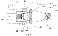
- FIG. 1 is a partial sectional view showing the overall configuration of a detachable implant-coupling prosthesis according to an embodiment of the present invention.
- the present invention is directed to a detachable implant-coupling prosthesis, which includes: an abutment 100 configured to be coupled to an implant 10 implanted for the placement of an implant; and a crown-coupling structure 200 configured such that a crown 20 is attached thereto and it is coupled to the abutment 100.
- An implant coupling portion 101 configured to be coupled to the implant 10 is formed on the abutment 100, and screw threads corresponding to those of the implant 10 are formed on the implant coupling portion 101.
- the crown-coupling structure 200 is coupled to the abutment 100.
- a coupling and separation tool entry part 211 is formed through the top end of the crown-coupling structure 200, and a crown attachment part 210 configured such that the crown 20 is attached thereonto is formed.
- crown 20 is preferably attached onto the crown attachment part 210 by using a method of attaching the crown 20 onto the outer side of crown attachment part 210 by means of an adhesive or the like, i.e., a typical method, a method of attaching the crown 20 is not limited to the method of performing attachment by using an adhesive.
- FIG. 1 the coupling portions are illustrated by means of a partial sectional view in order to illustrate the coupling portions in detail.
- the coupling between the abutment 100 and the crown-coupling structure 200 is achieved in such a manner that abutment fastening balls 270 are seated on a ball seat portion 151 formed on a coupling structure 150, thereby coupling the abutment 100 and the crown-coupling structure 200 to each other.
- the ball seat portion 151 is formed to be formed to be concave such that the abutment fastening balls 270 can be seated thereon.
- a locking ring 280 is formed to prevent the abutment 100 and the crown-coupling structure 200 from being separated from each other.
- the locking ring 280 is formed to surround the outer surface of the abutment coupling portion body 260 so that the abutment fastening balls 270 can come into tight contact with the surface of the ball seat portion 151.
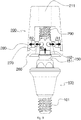
- FIG. 2 is an exploded view showing the overall disassembled configuration of the detachable implant-coupling prosthesis according to the embodiment of the present invention.
- the detachable implant-coupling prosthesis is formed by the coupling of the crown-coupling structure 200 and the abutment 100 into each other.
- the crown-coupling structure 200 is formed to include the crown attachment part 210 configured such that the crown 20 is attached thereonto and an abutment coupling unit 250 configured to function to be coupled to the abutment 100.
- the crown 20 is attached onto the outer circumferential surface of the crown attachment part 210, and the coupling and separation tool entry part 211 is formed through the top end of the crown attachment part 210.
- abutment fastening balls 270 and one locking ring rotation prevention ball 275 are formed.
- the abutment fastening balls 270 are accommodated in abutment fastening ball holes 261 one by one, and the locking ring rotation prevention ball 275 is seated in a rotation prevention ball accommodation depression 265.
- the abutment fastening balls 270 may be 7 or 8 in number, and locking ring rotation prevention ball 275 may be 2 or 3 in number, and thus the numbers of the balls are not limited the above-described numbers.
- the abutment coupling unit 250 includes the abutment coupling portion body 260 configured such that the coupling structure 150 formed on the top of the abutment 100 is inserted thereinto, the plurality of abutment fastening balls 270, and the locking ring 280 configured such that one side thereof is cut out. Accordingly, the abutment fastening balls 270 and the locking ring 280 are coupled to the abutment coupling portion body 260.
- the locking ring rotation prevention ball 275 is preferably formed in the cutout portion of the locking ring 280. The reason for this is to prevent the locking ring 280 from being rotated after being coupled.
- the plurality of abutment fastening ball holes 261 having a radius diminishing in an internal direction is formed in the abutment coupling portion body 260, and accommodates the abutment fastening balls 270.
- the locking ring 280 is coupled outside the plurality of abutment fastening ball holes 261 in which the abutment fastening balls 270 are accommodated, and fastens the abutment fastening balls 270 onto the ball seat portion 151 when it is coupled to the abutment 100.
- the locking ring 280 is formed such that one side thereof is cut out, and thus has predetermined elasticity.
- the locking ring 280 When the locking ring 280 is coupled to the abutment 100, the locking ring 280 disposed outside the abutment fastening balls 270 is slightly spread, and thus a space is formed between the abutment fastening balls 270, thereby allowing the coupling structure 150 to be inserted thereinto.
- the abutment fastening balls 270 are seated on the ball seat portion 151 formed on the coupling structure 150 accordingly, and the locking ring 280 brings the abutment fastening balls 270 into close contact with the ball seat portion 151 in order to prevent easy separation.
- the abutment 100 is formed to include the coupling structure 150 and the implant coupling portion 101.
- the coupling structure 150 is configured such that the ball seat portion 151 formed by bending an outer circumferential surface is formed such that the abutment fastening balls 270 can be seated thereon, and a polygonal head 152 is further formed on the top of the ball seat portion 151.
- the polygonal head 152 is coupled to a polygonal head accommodation portion 262 formed inside the abutment coupling portion body 260 and including a plurality of depressions, and prevents the crown-coupling structure 200 from being rotated after being coupled to the abutment 100.
- the crown-coupling structure 200 and the abutment 100 coupled to each other, as described above, may be easily separated by inserting a coupling separation tool 1 via coupling separation screw threads 290 formed inside the abutment coupling portion body 260 and the coupling and separation tool entry part 211 formed through the top of the crown attachment part 210.
- the coupling separation tool 1 configured such that screw threads corresponding to the coupling separation screw threads 290 are formed on the side thereof is inserted into the coupling and separation tool entry part 211 formed to communicate with the coupling separation screw threads 290 and is then rotated, and thus the abutment 100 is pushed, thereby easily separating the abutment 100 and the crown-coupling structure 200 from each other.
- the polygonal head 152 is preferably formed in a polygonal shape in order to prevent the crown-coupling structure 200 coupled to the abutment 100 from being rotated.
- the polygonal head 152 may be formed in a circular shape or any other shape, as desired.
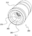
- FIG. 3 is a perspective view showing the overall configuration of the crown-coupling structure 200 of the detachable implant-coupling prosthesis according to an embodiment of the present invention.
- the appearance of the crown-coupling structure 200 is shown when viewed from below. Via the polygonal head accommodation portion 262 formed inside the abutment coupling portion body 260 and having a plurality of depressions, the crown-coupling structure 200 is prevented from being rotated after being coupled to the abutment 100.
- FIG. 4 is an exploded view showing the overall disassembled configuration of the crown-coupling structure 200 of the detachable implant-coupling prosthesis according to an embodiment of the present invention.
- FIG. 4 shows the overall disassembled configuration of the crown-coupling structure 200.
- the locking ring rotation prevention ball 275 is disposed to be located in the cutout portion of the locking ring 280.
- the locking ring rotation prevention ball 275 is seated on and fastened onto the rotation prevention ball accommodation depression 265 formed on the abutment coupling portion body 260.
- the locking ring rotation prevention ball 275 is located in the cutout portion of the locking ring 280, and functions to prevent the locking ring 280 from being rotated.
- FIG. 5 is a perspective view showing the crown-coupling structure 200 according to the embodiment of the present invention, i.e., a configuration in which the abutment fastening balls 270 are coupled to the abutment coupling portion body 260.
- the abutment fastening balls 270 are accommodated in the abutment fastening ball holes 261, and the locking ring rotation prevention ball 275 is located in the rotation prevention ball accommodation depression 256.
- FIG. 6 is a perspective view showing a configuration in which the abutment fastening balls 270 and the locking ring 280 are coupled to the abutment coupling portion body 260 according to an embodiment of the present invention.
- the locking ring 280 is coupled to the outer surface of the abutment coupling portion body 260 on which the abutment fastening ball holes 261 and the rotation prevention ball accommodation depressions 265 in which the abutment fastening balls 270 are accommodated are located, and the locking ring rotation prevention ball 275 is coupled into the cutout portion of the locking ring 280.
- FIG. 7 is a sectional view showing a cut surface obtained by cutting the crown-coupling structure 200 according to an embodiment of the present invention in direction C.
- FIG. 7 an internal cut surface obtained by cutting the crown-coupling structure 200 in the direction C is shown.
- FIG. 7 showing the coupling relationship between the abutment fastening ball holes 261, the abutment fastening balls 270, the locking ring rotation prevention ball 275, and the locking ring 280.
- FIG. 8 is a perspective view showing the overall configuration of the abutment 100 according to an embodiment of the present invention.
- the abutment 100 includes the implant coupling portion 101 configured to be coupled to the implant 10, and the coupling structure 150 configured to be coupled to the crown-coupling structure 200.
- the ball seat portion 151 formed by bending the outer circumferential surface is formed in the upper portion of the abutment 100, and the polygonal head 152 is formed on the top of the ball seat portion 151.
- FIGS. 9 to 10 are views showing the process of coupling the abutment 100 and the crown-coupling structure 200 to each other.
- the process of coupling the abutment 100 and the crown-coupling structure 200 to each other is performed, as follows:
- the upper portion of the abutment 100, i.e., the coupling structure 150, is inserted in direction R3 toward the bottom of the abutment coupling portion body 260 in the crown-coupling structure 200.
- the coupling structure 150 is coupled while pushing the abutment fastening balls 270 in directions R1 and R2.
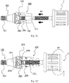
- FIGS. 11 to 13 are views showing the process of separating the abutment 100 and the crown-coupling structure 200 from each other.
- the process of separating the abutment 100 and the crown-coupling structure 200 from each other abutment 100 crown-coupling structure 200 is performed, as follows:
- the abutment 100 and the crown-coupling structure 200 coupled to each other are preferably separated using the coupling separation tool 1 configured such that the screw threads are formed one side thereof.
- the screw threads of the coupling separation tool 1 are formed to correspond to the coupling separation screw threads 290 formed on the abutment coupling portion body 260, and a grip which is easy to grip and rotate is preferably formed on the other side of the coupling separation tool 1.
- the reason for this is to easily separate the abutment 100 and the crown-coupling structure 200 by rotating the coupling separation tool 1.
- the coupling separation tool 1 is inserted into the coupling and separation tool entry part 211, i.e., in direction R6 (see FIG. 11 ), and the screw threads of the coupling separation tool 1 are brought into contact with the coupling separation screw threads 290 and are then rotated in direction R7 (see FIG. 12 ).
- the coupling separation tool 1 is engaged with the coupling separation screw threads 290, and simultaneously pushes the upper portion of the abutment 100, i.e., the polygonal head 152.
- the abutment 100 is pushed in direction R8 (see FIG. 13 ), and thus the coupling of the crown-coupling structure 200 and the abutment 100 is easily released.
- FIG. 14 is a perspective view showing the overall configuration of the detachable implant-coupling prosthesis according to the embodiment of the present invention.
- FIG. 14 is a perspective view showing the assembled detachable implant-coupling prosthesis.
- FIG. 15 is a view showing a scene of the placement of the crown-coupling structure 200 onto which the crown 20 has been attached.
- the abutment 100 is coupled to the implant 10 implanted into gums A, and the crown-coupling structure 200 onto which the crown is attached is coupled to the top of the abutment 100.
- the coupling structure 150 may be formed in a structure which becomes narrower in a direction toward the upper portion thereof, and thus an advantage arises in that freely coupling can be performed within region B.
- the above-described present invention is directed to the detachable implant-coupling prosthesis which can be easily fastened and separated via the unique distinguishing structure capable of overcoming a screw loosening phenomenon and a screw cutting phenomenon generated due to a conventionally used screw fastening method, overcoming the disadvantage in which an aesthetic effect and durability are degraded because a hole must be formed in a tooth in order to fasten the tooth to an implant, and overcoming the disadvantage in which a tooth (a crown, or a metal) must be destructed when a problem occurs after the placement of an implant, so that re-placement and revision are enabled because the detachable implant-coupling prosthesis can be easily separated without destructing a tooth when a problem occurs after the placement of an implant, so that loosening and fracture do not occur because a screw fastening method is not used, and so that high durability can be provided because it is not necessary to form a hole in a tooth.
- the present invention relates to a detachable implant-coupling prosthesis designed to be detachable such that an implant and a coupling prosthesis can be easily coupled to and separated from each other during revision and re-placement.
- the coupling prosthesis can be easily separated without destructing a tooth when a problem occurs after the placement of an implant, and thus effects arise in that the inconvenience of a patient can be mitigated and cost can be reduced during the treatment of inflammation or periodontitis.
- the present invention is applicable to implant treatment.
Landscapes
- Health & Medical Sciences (AREA)
- Oral & Maxillofacial Surgery (AREA)
- Orthopedic Medicine & Surgery (AREA)
- Dentistry (AREA)
- Epidemiology (AREA)
- Life Sciences & Earth Sciences (AREA)
- Animal Behavior & Ethology (AREA)
- General Health & Medical Sciences (AREA)
- Public Health (AREA)
- Veterinary Medicine (AREA)
- Dental Prosthetics (AREA)
- Prostheses (AREA)
Abstract
Description
- The present invention relates to a detachable implant-coupling prosthesis, and more specifically to a coupling prosthesis configured to be coupled to a placed implant, i.e., a detachable implant-coupling prosthesis designed to be detachable such that an implant and a coupling prosthesis can be easily coupled to and separated from each other during revision and re-placement.
- A tooth implant is a fixture which is placed in or on the jawbone for restoring a missing tooth.
- A tooth implant is usually called an artificial tooth or third tooth which is placed in the gums and the gum bone.
- Implantation is a dental treatment technique designed to recover the function of a natural tooth by placing a biocompatible implant body into the jaw bone the volume of which has been increased by applying an additional operation, such as bone graft, distraction osteogenesis, or the like, to the jaw bone where a tooth is defective or extracted.
- After osseointegration, i.e., the morphological, physiological, and direct coupling between the jawbone, in which a normal function is maintained, and the surface of the body of the placed implant, has been achieved, the bone is subjected to the process of revising the jaw bone around the implant.
- Such implants are generally used in the form of screw-shaped bone implants, and the upper structures (abutment) of the implants are fastened by screws.
- As described above, in the conventional method of perform fastening by means of a screw fastening method, there are cases where a screw is loosened or cut.
- Furthermore, an aesthetic effect and durability are degraded because a hole must be formed in a tooth in order to fasten the tooth to an implant, and a tooth (a crown, or metal) must be destructed when a problem occurs after the placement of an implant.
- The conventional method of performing fastening by means of a screw fastening method is problematic in that it causes inconvenience to patients due to additional cost and the time spent for additional treatment and placement, inconvenience is caused in that an adhesive must be applied in an oral cavity during the coupling of a crown and a coupling structure to each other, and inflammation and periodontitis are often caused by a residual adhesive.
- In order to solve this problem, the present invention provides a prosthesis in which, via the unique distinguishing structure capable of achieving easy coupling without using a screw fastening method screw fastening method, loosening and fracture do not occur, and an aesthetic effect and durability can be prevented from being degraded because it is not necessary to form a hole in a tooth.
- Furthermore, there has been developed a detachable implant-coupling prosthesis which can be easily separated without destructing a tooth when a problem occurs after the placement of an implant, thereby removing the inconvenience of patients.
- The present invention has been conceived to overcome the above-described problems, and an object of the present invention is to provide a detachable implant-coupling prosthesis in which, in order to overcome a screw loosening phenomenon and a screw cutting phenomenon generated due to a conventionally used screw fastening method,
- to overcome the disadvantage in which an aesthetic effect and durability are degraded because a hole must be formed in a tooth in order to fasten the tooth to an implant, and to overcome the disadvantage in which a tooth (a crown, or a metal) must be destructed when a problem occurs after the placement of an implant, a coupling prosthesis without loosening and fracture is provided via a unique distinguishing structure capable of achieving easy coupling without using a screw fastening method and the coupling prosthesis can be easily separated without destructing a tooth when a problem occurs after the placement of an implant.
- In order to accomplish the above object, the technical solution of the present invention is proposed, as follows:
- The technical problem of the present invention is solved by a detachable implant-coupling prosthesis coupled to an implant (10), the detachable implant-coupling prosthesis including: an abutment (100) configured to be coupled to the top of the implant (10); and a crown-coupling structure (200) configured such that it is coupled to the top of the abutment (100) and a crown (20) is attached onto the top thereof;
- wherein the abutment (100) includes: an implant coupling portion (101) configured to be coupled to the implant (10); and a crown-coupling structure (200) configured to be coupled to a coupling structure (150);
- wherein a ball seat portion (151) formed by bending an upper outer circumferential surface of the abutment (100) inward is formed on the coupling structure (150);
- wherein a coupling and separation tool entry part (211) formed to be penetrated in a vertical direction and configured to receive a coupling separation tool (1) in which screw threads are formed on one side thereof, a crown attachment part (210) configured such that the crown (20) is attached thereto, and an abutment coupling unit (250) configured to be coupled to the abutment (100) are formed in the crown-coupling structure (200) ;
- wherein the abutment coupling unit (250) includes: an abutment coupling portion body (260) configured such that the coupling structure (150) is inserted thereinto; a plurality of abutment fastening balls (270); and a locking ring (280) configured such that one side thereof is cut out;
- wherein coupling separation screw threads (290) formed to communicate with the coupling and separation tool entry part (211) are formed on the abutment coupling portion body (260), and a plurality of abutment fastening ball holes (261) formed to have a radius diminishing gradually in an internal direction is formed on the outer circumferential surface of the abutment coupling portion body (260);
- wherein the coupling separation screw threads (290) are formed to correspond to the screw threads formed on one side of the coupling separation tool (1);
- wherein the abutment fastening holes (261) accommodate the abutment fastening balls (270) accordingly; and
- wherein the locking ring (280) is coupled outside the plurality of abutment fastening ball holes (261) in which the abutment fastening balls (270) are accommodated, and is formed to fasten the abutment fastening balls (270) onto the ball seat portion (151) upon coupling with the abutment (100).
- The present invention provides the following effects.
- In other words, via the unique distinguishing structure capable of achieving easy coupling without using a screw fastening method screw fastening method, loosening and fracture do not occur, and an aesthetic effect and durability can be prevented from being degraded because it is not necessary to form a hole in a tooth.
- Furthermore, the coupling prosthesis can be easily separated without destructing a tooth when a problem occurs after the placement of an implant, and thus effects arise in that the inconvenience of a patient can be mitigated and cost can be reduced during the treatment of inflammation or periodontitis.
-
-
FIG. 1 is a partial sectional view showing the overall configuration of a detachable implant-coupling prosthesis according to an embodiment of the present invention; -
FIG. 2 is an exploded view showing the disassembled overall configuration of the detachable implant-coupling prosthesis according to the embodiment of the present invention; -
FIG. 3 is a perspective view showing the overall configuration of the crown-coupling structure (200) of the detachable implant-coupling prosthesis according to the embodiment of the present invention; -
FIG. 4 is an exploded view showing the overall disassembled configuration of the crown-coupling structure (200) of the detachable implant-coupling prosthesis according to the embodiment of the present invention; -
FIG. 5 is a perspective view showing a configuration in which abutment fastening balls (270) are coupled to an abutment coupling portion body (260); -
FIG. 6 is a perspective view showing a configuration in which the abutment fastening balls (270) and a locking ring (280) are coupled to the abutment coupling portion body (260) according to an embodiment of the present invention; -
FIG. 7 is a sectional view showing a cut surface obtained by cutting a crown-coupling structure (200) in direction C; -
FIG. 8 is a perspective view showing the overall configuration of an abutment (100) according to an embodiment of the present invention; -
FIGS. 9 to 10 are views showing the process of coupling the abutment (100) and the crown-coupling structure (200) to each other; -
FIGS. 11 to 13 are views showing the process of separating the abutment (100) and the crown-coupling structure (200) from each other; -
FIG. 14 is a perspective view showing the overall configuration of the detachable implant-coupling prosthesis according to the embodiment of the present invention; and -
FIG. 15 is a view showing a scene of the placement of the crown-coupling structure (200) onto which the crown (20) has been attached. - The best solution of the invention is:
- a detachable implant-coupling prosthesis coupled to an implant (10), the detachable implant-coupling prosthesis including: an abutment (100) configured to be coupled to the top of the implant (10); and a crown-coupling structure (200) configured such that it is coupled to the top of the abutment (100) and a crown (20) is attached onto the top thereof;
- wherein the abutment (100) includes: an implant coupling portion (101) configured to be coupled to the implant (10); and a crown-coupling structure (200) configured to be coupled to a coupling structure (150);
- wherein a ball seat portion (151) formed by bending an upper outer circumferential surface of the abutment (100) inward is formed on the coupling structure (150);
- wherein a coupling and separation tool entry part (211) formed to be penetrated in a vertical direction and configured to receive a coupling separation tool (1) in which screw threads are formed on one side thereof, a crown attachment part (210) configured such that the crown (20) is attached thereto, and an abutment coupling unit (250) configured to be coupled to the abutment (100) are formed in the crown-coupling structure (200) ;
- wherein the abutment coupling unit (250) includes: an abutment coupling portion body (260) configured such that the coupling structure (150) is inserted thereinto; a plurality of abutment fastening balls (270); and a locking ring (280) configured such that one side thereof is cut out;
- wherein coupling separation screw threads (290) formed to communicate with the coupling and separation tool entry part (211) are formed on the abutment coupling portion body (260), and a plurality of abutment fastening ball holes (261) formed to have a radius diminishing gradually in an internal direction is formed on the outer circumferential surface of the abutment coupling portion body (260);
- wherein the coupling separation screw threads (290) are formed to correspond to the screw threads formed on one side of the coupling separation tool (1);
- wherein the abutment fastening holes (261) accommodate the abutment fastening balls (270) accordingly; and
- wherein the locking ring (280) is coupled outside the plurality of abutment fastening ball holes (261) in which the abutment fastening balls (270) are accommodated, and is formed to fasten the abutment fastening balls (270) onto the ball seat portion (151) upon coupling with the abutment (100).
- Preferred embodiments of the present invention will be described in detail below in mode for invention with reference to the accompanying drawings.
- First, it should be noted that throughout the drawings, the same components or parts are denoted by the same reference symbols as much as possible.
- In the description of the present invention, detailed descriptions of related well-known functions or components will be omitted in order to prevent the gist of the present invention from being made obscure.
- The terms "about," "substantially," etc. used herein are used to mean closeness to a corresponding numerical value when a unique manufacturing or material tolerance is proposed in mentioned context, and are used to prevent a scrupulous infringer from illegitimately using disclosure in which an accurate or absolute numeral value is described in order to help to understand the present invention.
- First, the present invention is summarized, as follows:
In other words, the present invention is directed to a detachable implant-coupling prosthesis coupled to animplant 10, the detachable implant-coupling prosthesis including: anabutment 100 configured to be coupled to the top of theimplant 10; and a crown-coupling structure 200 configured such that it is coupled to the top of theabutment 100 and acrown 20 is attached onto the top thereof; wherein theabutment 100 includes: animplant coupling portion 101 configured to be coupled to theimplant 10; and a crown-coupling structure 200 configured to be coupled to acoupling structure 150; wherein aball seat portion 151 formed by bending an upper outer circumferential surface of theabutment 100 inward is formed on thecoupling structure 150; wherein a coupling and separationtool entry part 211 formed to be penetrated in a vertical direction and configured to receive acoupling separation tool 1 in which screw threads are formed on one side thereof, acrown attachment part 210 configured such that thecrown 20 is attached thereto, and anabutment coupling unit 250 configured to be coupled to theabutment 100 are formed in the crown-coupling structure 200; wherein theabutment coupling unit 250 includes: an abutmentcoupling portion body 260 configured such that thecoupling structure 150 is inserted thereinto; a plurality ofabutment fastening balls 270; and alocking ring 280 configured such that one side thereof is cut out; wherein couplingseparation screw threads 290 formed to communicate with the coupling and separationtool entry part 211 are formed on the abutmentcoupling portion body 260, and a plurality of abutment fasteningball holes 261 formed to have a radius diminishing gradually in an internal direction is formed on the outer circumferential surface of the abutmentcoupling portion body 260; wherein the couplingseparation screw threads 290 are formed to correspond to the screw threads formed on one side of thecoupling separation tool 1; wherein the abutment fasteningholes 261 accommodate theabutment fastening balls 270 accordingly; and wherein thelocking ring 280 is coupled outside the plurality of abutment fasteningball holes 261 in which theabutment fastening balls 270 are accommodated, and is formed to fasten theabutment fastening balls 270 onto theball seat portion 151 upon coupling with theabutment 100. Thecoupling structure 150 further includes apolygonal head 152 formed on a top of theball seat portion 151 in a polygonal shape; and a polygonalhead accommodation portion 262 configured such that a plurality of depressions corresponding to thepolygonal head 152 is formed is formed in the abutmentcoupling portion body 260, thereby preventing the crown-coupling structure 200 from being rotated after coupling with the crown-coupling structure 200. Theabutment coupling unit 250 further includes a locking ringrotation prevention ball 275 configured to be located in a cutout portion of thelocking ring 280; and a rotation preventionball accommodation depression 265 corresponding to the locking ringrotation prevention ball 275 is formed in the abutmentcoupling portion body 260, thereby preventing thelocking ring 280 from being rotated after coupling with the crown-coupling structure 200. - The present invention is directed to a detachable implant-coupling prosthesis which can overcome a screw loosening phenomenon and a screw cutting phenomenon generated due to a conventionally used screw fastening method, overcome the disadvantage in which an aesthetic effect and durability are degraded because a hole must be formed in a tooth in order to fasten the tooth to an implant, and overcome the disadvantage in which a tooth (a crown, or a metal) must be destructed when a problem occurs after the placement of an implant, which does not cause loosening and fracture via a unique distinguishing structure capable of achieving easy coupling without using a screw fastening method, and which can be easily separated without destructing a tooth when a problem occurs after the placement of an implant.
-
FIG. 1 is a partial sectional view showing the overall configuration of a detachable implant-coupling prosthesis according to an embodiment of the present invention. - As shown in
FIG. 1 , the present invention is directed to a detachable implant-coupling prosthesis, which includes: anabutment 100 configured to be coupled to animplant 10 implanted for the placement of an implant; and a crown-coupling structure 200 configured such that acrown 20 is attached thereto and it is coupled to theabutment 100. - An
implant coupling portion 101 configured to be coupled to theimplant 10 is formed on theabutment 100, and screw threads corresponding to those of theimplant 10 are formed on theimplant coupling portion 101. - The crown-
coupling structure 200 is coupled to theabutment 100. In the crown-coupling structure 200, a coupling and separationtool entry part 211 is formed through the top end of the crown-coupling structure 200, and acrown attachment part 210 configured such that thecrown 20 is attached thereonto is formed. - Although the
crown 20 is preferably attached onto thecrown attachment part 210 by using a method of attaching thecrown 20 onto the outer side ofcrown attachment part 210 by means of an adhesive or the like, i.e., a typical method, a method of attaching thecrown 20 is not limited to the method of performing attachment by using an adhesive. - The coupling portions of the
abutment 100 and the crown-coupling structure 200 will be described in detail, as follows:
InFIG. 1 , the coupling portions are illustrated by means of a partial sectional view in order to illustrate the coupling portions in detail. - The coupling between the
abutment 100 and the crown-coupling structure 200 is achieved in such a manner thatabutment fastening balls 270 are seated on aball seat portion 151 formed on acoupling structure 150, thereby coupling theabutment 100 and the crown-coupling structure 200 to each other. - As can be seen from
FIG. 9 , theball seat portion 151 is formed to be formed to be concave such that theabutment fastening balls 270 can be seated thereon. - Furthermore, a
locking ring 280 is formed to prevent theabutment 100 and the crown-coupling structure 200 from being separated from each other. Thelocking ring 280 is formed to surround the outer surface of the abutmentcoupling portion body 260 so that theabutment fastening balls 270 can come into tight contact with the surface of theball seat portion 151. -
FIG. 2 is an exploded view showing the overall disassembled configuration of the detachable implant-coupling prosthesis according to the embodiment of the present invention. - As shown in
FIG. 2 , the overall configuration of the detachable implant-coupling prosthesis is as follows:
The detachable implant-coupling prosthesis is formed by the coupling of the crown-coupling structure 200 and theabutment 100 into each other. - The crown-
coupling structure 200 is formed to include thecrown attachment part 210 configured such that thecrown 20 is attached thereonto and anabutment coupling unit 250 configured to function to be coupled to theabutment 100. - The
crown 20 is attached onto the outer circumferential surface of thecrown attachment part 210, and the coupling and separationtool entry part 211 is formed through the top end of thecrown attachment part 210. - Referring to
FIG. 2 , sixabutment fastening balls 270 and one locking ringrotation prevention ball 275 are formed. Theabutment fastening balls 270 are accommodated in abutment fastening ball holes 261 one by one, and the locking ringrotation prevention ball 275 is seated in a rotation preventionball accommodation depression 265. Furthermore, theabutment fastening balls 270 may be 7 or 8 in number, and locking ringrotation prevention ball 275 may be 2 or 3 in number, and thus the numbers of the balls are not limited the above-described numbers. - More specifically, the
abutment coupling unit 250 includes the abutmentcoupling portion body 260 configured such that thecoupling structure 150 formed on the top of theabutment 100 is inserted thereinto, the plurality ofabutment fastening balls 270, and thelocking ring 280 configured such that one side thereof is cut out. Accordingly, theabutment fastening balls 270 and thelocking ring 280 are coupled to the abutmentcoupling portion body 260. - Furthermore, the locking ring
rotation prevention ball 275 is preferably formed in the cutout portion of thelocking ring 280. The reason for this is to prevent thelocking ring 280 from being rotated after being coupled. - The plurality of abutment fastening ball holes 261 having a radius diminishing in an internal direction is formed in the abutment
coupling portion body 260, and accommodates theabutment fastening balls 270. - The
locking ring 280 is coupled outside the plurality of abutment fastening ball holes 261 in which theabutment fastening balls 270 are accommodated, and fastens theabutment fastening balls 270 onto theball seat portion 151 when it is coupled to theabutment 100. - The
locking ring 280 is formed such that one side thereof is cut out, and thus has predetermined elasticity. - When the
locking ring 280 is coupled to theabutment 100, thelocking ring 280 disposed outside theabutment fastening balls 270 is slightly spread, and thus a space is formed between theabutment fastening balls 270, thereby allowing thecoupling structure 150 to be inserted thereinto. - After the
coupling structure 150 has been inserted, theabutment fastening balls 270 are seated on theball seat portion 151 formed on thecoupling structure 150 accordingly, and thelocking ring 280 brings theabutment fastening balls 270 into close contact with theball seat portion 151 in order to prevent easy separation. - The
abutment 100 is formed to include thecoupling structure 150 and theimplant coupling portion 101. - The
coupling structure 150 is configured such that theball seat portion 151 formed by bending an outer circumferential surface is formed such that theabutment fastening balls 270 can be seated thereon, and
apolygonal head 152 is further formed on the top of theball seat portion 151. Although not shown, thepolygonal head 152 is coupled to a polygonalhead accommodation portion 262 formed inside the abutmentcoupling portion body 260 and including a plurality of depressions, and prevents the crown-coupling structure 200 from being rotated after being coupled to theabutment 100. - The crown-
coupling structure 200 and theabutment 100 coupled to each other, as described above, may be easily separated by inserting acoupling separation tool 1 via couplingseparation screw threads 290 formed inside the abutmentcoupling portion body 260 and the coupling and separationtool entry part 211 formed through the top of thecrown attachment part 210. - In other words, the
coupling separation tool 1 configured such that screw threads corresponding to the couplingseparation screw threads 290 are formed on the side thereof is inserted into the coupling and separationtool entry part 211 formed to communicate with the couplingseparation screw threads 290 and is then rotated, and thus theabutment 100 is pushed, thereby easily separating theabutment 100 and the crown-coupling structure 200 from each other. - The
polygonal head 152 is preferably formed in a polygonal shape in order to prevent the crown-coupling structure 200 coupled to theabutment 100 from being rotated. - However, when two or more teeth are placed, the two teeth are connected to each other and are placed, and thus the prevention of rotation is not required. Accordingly, in this case, the
polygonal head 152 may be formed in a circular shape or any other shape, as desired. -
FIG. 3 is a perspective view showing the overall configuration of the crown-coupling structure 200 of the detachable implant-coupling prosthesis according to an embodiment of the present invention. - As shown in
FIG. 3 , the appearance of the crown-coupling structure 200 is shown when viewed from below. Via the polygonalhead accommodation portion 262 formed inside the abutmentcoupling portion body 260 and having a plurality of depressions, the crown-coupling structure 200 is prevented from being rotated after being coupled to theabutment 100. -
FIG. 4 is an exploded view showing the overall disassembled configuration of the crown-coupling structure 200 of the detachable implant-coupling prosthesis according to an embodiment of the present invention. -
FIG. 4 shows the overall disassembled configuration of the crown-coupling structure 200. - As shown in this drawing, the locking ring
rotation prevention ball 275 is disposed to be located in the cutout portion of thelocking ring 280. - The locking ring
rotation prevention ball 275 is seated on and fastened onto the rotation preventionball accommodation depression 265 formed on the abutmentcoupling portion body 260. When the abutmentcoupling portion body 260 and thelocking ring 280 are coupled to each other, the locking ringrotation prevention ball 275 is located in the cutout portion of thelocking ring 280, and functions to prevent thelocking ring 280 from being rotated. -
FIG. 5 is a perspective view showing the crown-coupling structure 200 according to the embodiment of the present invention, i.e., a configuration in which theabutment fastening balls 270 are coupled to the abutmentcoupling portion body 260. - As shown in
FIG. 5 , theabutment fastening balls 270 are accommodated in the abutment fastening ball holes 261, and the locking ringrotation prevention ball 275 is located in the rotation prevention ball accommodation depression 256. -
FIG. 6 is a perspective view showing a configuration in which theabutment fastening balls 270 and thelocking ring 280 are coupled to the abutmentcoupling portion body 260 according to an embodiment of the present invention. - As shown in
FIGS. 5 and6 , thelocking ring 280 is coupled to the outer surface of the abutmentcoupling portion body 260 on which the abutment fastening ball holes 261 and the rotation preventionball accommodation depressions 265 in which theabutment fastening balls 270 are accommodated are located, and the locking ringrotation prevention ball 275 is coupled into the cutout portion of thelocking ring 280. -
FIG. 7 is a sectional view showing a cut surface obtained by cutting the crown-coupling structure 200 according to an embodiment of the present invention in direction C. - As shown in
FIG. 7 , an internal cut surface obtained by cutting the crown-coupling structure 200 in the direction C is shown.FIG. 7 showing the coupling relationship between the abutment fastening ball holes 261, theabutment fastening balls 270, the locking ringrotation prevention ball 275, and thelocking ring 280. -
FIG. 8 is a perspective view showing the overall configuration of theabutment 100 according to an embodiment of the present invention. - As shown in
FIG. 8 , theabutment 100 includes theimplant coupling portion 101 configured to be coupled to theimplant 10, and thecoupling structure 150 configured to be coupled to the crown-coupling structure 200. In thecoupling structure 150, theball seat portion 151 formed by bending the outer circumferential surface is formed in the upper portion of theabutment 100, and thepolygonal head 152 is formed on the top of theball seat portion 151. -
FIGS. 9 to 10 are views showing the process of coupling theabutment 100 and the crown-coupling structure 200 to each other. - The process of coupling the
abutment 100 and the crown-coupling structure 200 to each other is performed, as follows:
The upper portion of theabutment 100, i.e., thecoupling structure 150, is inserted in direction R3 toward the bottom of the abutmentcoupling portion body 260 in the crown-coupling structure 200. - In this case, the
coupling structure 150 is coupled while pushing theabutment fastening balls 270 in directions R1 and R2. - The
abutment fastening balls 270 pushed in the directions R1 and R2 move back in directions R4 and R5 by the elasticity of thelocking ring 280. During this process, theabutment fastening balls 270 are accommodated in and fastened onto theball seat portion 151 formed on theabutment 100. - Via this structure, easy coupling is enabled.
-
FIGS. 11 to 13 are views showing the process of separating theabutment 100 and the crown-coupling structure 200 from each other. - The process of separating the
abutment 100 and the crown-coupling structure 200 from eachother abutment 100crown-
coupling structure 200 is performed, as follows:
Theabutment 100 and the crown-coupling structure 200 coupled to each other are preferably separated using thecoupling separation tool 1 configured such that the screw threads are formed one side thereof. - The screw threads of the
coupling separation tool 1 are formed to correspond to the couplingseparation screw threads 290 formed on the abutmentcoupling portion body 260, and a grip which is easy to grip and rotate is preferably formed on the other side of thecoupling separation tool 1. - The reason for this is to easily separate the
abutment 100 and the crown-coupling structure 200 by rotating thecoupling separation tool 1. - The
coupling separation tool 1 is inserted into the coupling and separationtool entry part 211, i.e., in direction R6 (seeFIG. 11 ), and the screw threads of thecoupling separation tool 1 are brought into contact with the couplingseparation screw threads 290 and are then rotated in direction R7 (seeFIG. 12 ). - In this case, the
coupling separation tool 1 is engaged with the couplingseparation screw threads 290, and simultaneously pushes the upper portion of theabutment 100, i.e., thepolygonal head 152. - Accordingly, the
abutment 100 is pushed in direction R8 (seeFIG. 13 ), and thus the coupling of the crown-coupling structure 200 and theabutment 100 is easily released. -
FIG. 14 is a perspective view showing the overall configuration of the detachable implant-coupling prosthesis according to the embodiment of the present invention. -
FIG. 14 is a perspective view showing the assembled detachable implant-coupling prosthesis. -
FIG. 15 is a view showing a scene of the placement of the crown-coupling structure 200 onto which thecrown 20 has been attached. - As shown in
FIG. 15 , theabutment 100 is coupled to theimplant 10 implanted into gums A, and the crown-coupling structure 200 onto which the crown is attached is coupled to the top of theabutment 100. - This method enables fastening to be performed by easy pressing, unlike conventional technology in which placement is performed using a screw coupling method by rotating a crown. This method makes placement relatively simple. The
coupling structure 150 may be formed in a structure which becomes narrower in a direction toward the upper portion thereof, and thus an advantage arises in that freely coupling can be performed within region B. - The above-described present invention is directed to the detachable implant-coupling prosthesis which can be easily fastened and separated via the unique distinguishing structure capable of overcoming a screw loosening phenomenon and a screw cutting phenomenon generated due to a conventionally used screw fastening method, overcoming the disadvantage in which an aesthetic effect and durability are degraded because a hole must be formed in a tooth in order to fasten the tooth to an implant, and overcoming the disadvantage in which a tooth (a crown, or a metal) must be destructed when a problem occurs after the placement of an implant, so that re-placement and revision are enabled because the detachable implant-coupling prosthesis can be easily separated without destructing a tooth when a problem occurs after the placement of an implant, so that loosening and fracture do not occur because a screw fastening method is not used, and so that high durability can be provided because it is not necessary to form a hole in a tooth.
- The present invention described above is not limited by the above-described embodiment and the accompanying drawings. It will be apparent to those having ordinary knowledge in the art to which the present invention pertains that various substitutions, modifications, and alterations may be made without departing from technical spirit of the present invention.
- The present invention relates to a detachable implant-coupling prosthesis designed to be detachable such that an implant and a coupling prosthesis can be easily coupled to and separated from each other during revision and re-placement. The coupling prosthesis can be easily separated without destructing a tooth when a problem occurs after the placement of an implant, and thus effects arise in that the inconvenience of a patient can be mitigated and cost can be reduced during the treatment of inflammation or periodontitis. The present invention is applicable to implant treatment.
Claims (3)
- A detachable implant-coupling prosthesis coupled to an implant (10), the detachable implant-coupling prosthesis comprising:an abutment (100) configured to be coupled to a top of the implant (10); anda crown-coupling structure (200) configured such that it is coupled to a top of the abutment (100) and a crown (20) is attached onto a top thereof;wherein the abutment (100) comprises:an implant coupling portion (101) configured to be coupled to the implant (10); anda crown-coupling structure (200) configured to be coupled to a coupling structure (150);wherein a ball seat portion (151) formed by bending an upper outer circumferential surface of the abutment (100) inward is formed on the coupling structure (150);wherein a coupling and separation tool entry part (211) formed to be penetrated in a vertical direction and configured to receive a coupling separation tool (1) in which screw threads are formed on one side thereof, a crown attachment part (210) configured such that the crown (20) is attached thereto, and an abutment coupling unit (250) configured to be coupled to the abutment (100) are formed in the crown-coupling structure (200) ;wherein the abutment coupling unit (250) comprises:an abutment coupling portion body (260) configured such that the coupling structure (150) is inserted thereinto;a plurality of abutment fastening balls (270); anda locking ring (280) configured such that one side thereof is cut out;wherein:coupling separation screw threads (290) formed to communicate with the coupling and separation tool entry part (211) are formed on the abutment coupling portion body (260); anda plurality of abutment fastening ball holes (261) formed to have a radius diminishing gradually in an internal direction is formed on an outer circumferential surface of the abutment coupling portion body (260);wherein the coupling separation screw threads (290) are formed to correspond to the screw threads formed on one side of the coupling separation tool (1);wherein the abutment fastening holes (261) accommodate the abutment fastening balls (270) accordingly; andwherein the locking ring (280):is coupled outside the plurality of abutment fastening ball holes (261) in which the abutment fastening balls (270) are accommodated; andis formed to fasten the abutment fastening balls (270) onto the ball seat portion (151) upon coupling with the abutment (100).
- The detachable implant-coupling prosthesis of claim 1, wherein:the coupling structure (150) further comprises a polygonal head (152) formed on a top of the ball seat portion (151) in a polygonal shape; anda polygonal head accommodation portion (262) configured such that a plurality of depressions corresponding to the polygonal head (152) is formed is formed in the abutment coupling portion body (260), thereby preventing the crown-coupling structure (200) from being rotated after coupling with the crown-coupling structure (200).
- The detachable implant-coupling prosthesis of claim 1 or 2, wherein:the abutment coupling unit (250) further comprises a locking ring rotation prevention ball (275) configured to be located in a cutout portion of the locking ring (280); anda rotation prevention ball accommodation depression (265) corresponding to the locking ring rotation prevention ball (275) is formed in the abutment coupling portion body (260),thereby preventing the locking ring (280) from being rotated after coupling with the crown-coupling structure (200).
Applications Claiming Priority (2)
| Application Number | Priority Date | Filing Date | Title |
|---|---|---|---|
| KR1020160022364A KR101633259B1 (en) | 2016-02-25 | 2016-02-25 | Removable implant-bonded prosthesis |
| PCT/KR2017/001990 WO2017146478A1 (en) | 2016-02-25 | 2017-02-23 | Detachable implant-coupling prosthesis |
Publications (3)
| Publication Number | Publication Date |
|---|---|
| EP3421004A1 true EP3421004A1 (en) | 2019-01-02 |
| EP3421004A4 EP3421004A4 (en) | 2019-01-16 |
| EP3421004B1 EP3421004B1 (en) | 2020-07-15 |
Family
ID=56343560
Family Applications (1)
| Application Number | Title | Priority Date | Filing Date |
|---|---|---|---|
| EP17756816.9A Active EP3421004B1 (en) | 2016-02-25 | 2017-02-23 | Detachable dental implant-coupling prosthesis |
Country Status (6)
| Country | Link |
|---|---|
| US (1) | US10617493B2 (en) |
| EP (1) | EP3421004B1 (en) |
| JP (1) | JP6569993B2 (en) |
| KR (1) | KR101633259B1 (en) |
| CN (1) | CN108697492B (en) |
| WO (1) | WO2017146478A1 (en) |
Cited By (2)
| Publication number | Priority date | Publication date | Assignee | Title |
|---|---|---|---|---|
| FR3125960A1 (en) | 2021-08-08 | 2023-02-10 | Rémy Tanimura | CONNECTING DEVICE AND CONNECTING SYSTEM FOR DENTAL RECONSTRUCTION ON IMPLANT, DENTAL RECONSTRUCTION ON IMPLANT, METHOD FOR PERFORMING DENTAL RECONSTRUCTION ON IMPLANT |
| WO2023016787A1 (en) | 2021-08-08 | 2023-02-16 | Ajust Sàrl | Connection device and connection system for dental reconstruction on an implant, dental reconstruction on an implant, and method for performing dental reconstruction on an implant |
Families Citing this family (14)
| Publication number | Priority date | Publication date | Assignee | Title |
|---|---|---|---|---|
| WO2014108327A1 (en) * | 2013-01-10 | 2014-07-17 | Straumann Holding Ag | Annular resilient retention member |
| KR101386560B1 (en) * | 2013-11-21 | 2014-04-17 | 김윤자 | Dental implant |
| KR101633259B1 (en) * | 2016-02-25 | 2016-06-24 | 채희진 | Removable implant-bonded prosthesis |
| KR101840672B1 (en) * | 2017-11-10 | 2018-03-21 | 윤장훈 | Artificial tooth fixing device |
| KR102097423B1 (en) * | 2018-03-15 | 2020-04-06 | 부산대학교 산학협력단 | Detachable implant structure for preventing abutment sinking |
| IL262374A (en) | 2018-10-14 | 2020-04-30 | Abracadabra Implant Ltd | Dental implant device and system |
| KR102097376B1 (en) * | 2019-10-18 | 2020-04-06 | 채희진 | Implants that can distribute the force of the implants and are easy to detachable |
| KR102604677B1 (en) | 2021-05-25 | 2023-11-24 | 부산대학교 산학협력단 | Dental Implant Structure with Dual Retention Structure and Digital Prosthetic System for Manufacturing Dental Implant Structure |
| KR102454967B1 (en) * | 2022-01-05 | 2022-10-13 | 김경록 | Dental Implant system |
| KR102695374B1 (en) * | 2022-02-18 | 2024-08-14 | 주식회사 네오바이오텍 | Dental implant system for denture |
| KR102449647B1 (en) * | 2022-03-31 | 2022-09-30 | 주식회사 피엔유에드 | Fixing structure for dental implant and dental implant structure comprising same |
| WO2023191419A1 (en) * | 2022-03-31 | 2023-10-05 | 주식회사 피엔유에드 | Fixing structure for dental implant and dental implant structure comprising same |
| KR102518424B1 (en) * | 2022-09-08 | 2023-04-05 | 오스테오바이오닉스 주식회사 | Implant abutment module with ball |
| IT202300025761A1 (en) * | 2023-12-04 | 2025-06-04 | Rhein 83 S R L | KIT FOR DENTAL APPLICATIONS. |
Family Cites Families (33)
| Publication number | Priority date | Publication date | Assignee | Title |
|---|---|---|---|---|
| DE8909755U1 (en) * | 1989-02-28 | 1989-10-05 | Si-tec GmbH, 58285 Gevelsberg | Telescopic crown |
| US5049072A (en) * | 1990-06-26 | 1991-09-17 | Calcitek, Inc. | O-ring attachment system for dental prosthesis |
| JPH05168651A (en) * | 1991-02-26 | 1993-07-02 | Lion Corp | Artificial tooth root |
| WO1998032393A1 (en) * | 1997-01-27 | 1998-07-30 | Implant Innovations, Inc. | Abutment and coping system for use with dental implants |
| US6619958B2 (en) * | 1997-04-09 | 2003-09-16 | Implant Innovations, Inc. | Implant delivery system |
| DE29711621U1 (en) * | 1997-07-03 | 1997-11-20 | Rinceanu, Nicolae, 79114 Freiburg | Micro latch for implant-supported dentures |
| DE10164323C1 (en) * | 2001-12-28 | 2003-06-18 | Biedermann Motech Gmbh | Bone screw has holder element joined to shaft and possessing two free arms , with inner screw, slot, external nut, cavity and shoulder cooperating with attachment |
| US6986660B2 (en) * | 2002-06-04 | 2006-01-17 | Zimmer Dental, Inc. | Retaining screw with rententive feature |
| US7066736B2 (en) * | 2002-09-12 | 2006-06-27 | Zimmer Dental, Inc. | Dental impression coping with retention |
| US7377923B2 (en) * | 2003-05-22 | 2008-05-27 | Alphatec Spine, Inc. | Variable angle spinal screw assembly |
| US8152810B2 (en) * | 2004-11-23 | 2012-04-10 | Jackson Roger P | Spinal fixation tool set and method |
| CN1561929A (en) * | 2004-03-16 | 2005-01-12 | 崔宏斌 | Suspending dental crown type implanting tooth |
| FR2873284A1 (en) * | 2004-07-20 | 2006-01-27 | Jacob Jacque Hania | Screw-free device for fixing the column onto the implant in dental prosthesis production, comprising male fixing pieces on column and corresponding cavities on internal face of collar |
| FR2873285A1 (en) * | 2004-07-20 | 2006-01-27 | Jacob Hania | DEVICE FOR ATTACHING A PILLAR SUPPORT OF PROSTHESIS TO A DENTAL IMPLANT |
| US7691129B2 (en) * | 2004-10-27 | 2010-04-06 | Felix Brent A | Spinal stabilizing system |
| US7875065B2 (en) * | 2004-11-23 | 2011-01-25 | Jackson Roger P | Polyaxial bone screw with multi-part shank retainer and pressure insert |
| WO2008062418A2 (en) * | 2006-11-22 | 2008-05-29 | Eliezer Bar Shalom | Multi-position abutment with angular ball attachment for dental implants |
| KR100884614B1 (en) * | 2007-05-28 | 2009-02-23 | 이규호 | Dental implant |
| US8998958B2 (en) * | 2007-12-20 | 2015-04-07 | Aesculap Implant Systems, Llc | Locking device introducer instrument |
| KR101029065B1 (en) * | 2009-02-24 | 2011-04-15 | (주) 시원 | Dental implant |
| US8241341B2 (en) * | 2009-03-20 | 2012-08-14 | Spinal Usa, Inc. | Pedicle screws and methods of using the same |
| EP2727546A3 (en) * | 2009-08-20 | 2014-07-30 | Biedermann Technologies GmbH & Co. KG | Bone anchoring device, tool and method for assembling the same and tool for use with the same |
| US8714056B2 (en) * | 2010-09-03 | 2014-05-06 | Greatbatch Ltd. | Torque limiting mechanism with lock bushing |
| AU2012242511B2 (en) * | 2011-04-15 | 2016-07-07 | Jbsg Management Llc | Polyaxial dental implant system |
| BRMU9101148Y1 (en) * | 2011-06-14 | 2018-05-08 | Cândia Alba Junior Rodolfo | arrangement introduced in instrument for osseointegration screw installation |
| KR101548805B1 (en) * | 2013-09-23 | 2015-08-31 | 경북대학교 산학협력단 | Dental Implant using shock absorber |
| KR101386560B1 (en) * | 2013-11-21 | 2014-04-17 | 김윤자 | Dental implant |
| US9931181B2 (en) * | 2014-07-22 | 2018-04-03 | Zest Ip Holdings, Llc | Fixed hybrid dental attachment assembly and methods of use |
| KR101537233B1 (en) | 2014-12-22 | 2015-08-07 | 태광바이오테크주식회사 | A dental implant having a fixture of two lines thread way |
| KR101728424B1 (en) * | 2015-07-14 | 2017-05-24 | 주식회사 덴플렉스 | Dental implant |
| WO2017070358A1 (en) * | 2015-10-21 | 2017-04-27 | Biomet 3I, Llc | Attachment members with internally located radiopaque information markers for ct scan |
| KR101633259B1 (en) * | 2016-02-25 | 2016-06-24 | 채희진 | Removable implant-bonded prosthesis |
| US11925527B2 (en) * | 2017-09-12 | 2024-03-12 | Carlos M. Valverde | Dental implant device and technique |
-
2016
- 2016-02-25 KR KR1020160022364A patent/KR101633259B1/en active Active
-
2017
- 2017-02-23 WO PCT/KR2017/001990 patent/WO2017146478A1/en not_active Ceased
- 2017-02-23 US US16/077,534 patent/US10617493B2/en active Active
- 2017-02-23 JP JP2018545228A patent/JP6569993B2/en active Active
- 2017-02-23 EP EP17756816.9A patent/EP3421004B1/en active Active
- 2017-02-23 CN CN201780011663.5A patent/CN108697492B/en not_active Expired - Fee Related
Cited By (2)
| Publication number | Priority date | Publication date | Assignee | Title |
|---|---|---|---|---|
| FR3125960A1 (en) | 2021-08-08 | 2023-02-10 | Rémy Tanimura | CONNECTING DEVICE AND CONNECTING SYSTEM FOR DENTAL RECONSTRUCTION ON IMPLANT, DENTAL RECONSTRUCTION ON IMPLANT, METHOD FOR PERFORMING DENTAL RECONSTRUCTION ON IMPLANT |
| WO2023016787A1 (en) | 2021-08-08 | 2023-02-16 | Ajust Sàrl | Connection device and connection system for dental reconstruction on an implant, dental reconstruction on an implant, and method for performing dental reconstruction on an implant |
Also Published As
| Publication number | Publication date |
|---|---|
| EP3421004A4 (en) | 2019-01-16 |
| CN108697492A (en) | 2018-10-23 |
| US20190029780A1 (en) | 2019-01-31 |
| KR101633259B1 (en) | 2016-06-24 |
| JP2019506257A (en) | 2019-03-07 |
| EP3421004B1 (en) | 2020-07-15 |
| CN108697492B (en) | 2020-12-29 |
| WO2017146478A1 (en) | 2017-08-31 |
| US10617493B2 (en) | 2020-04-14 |
| JP6569993B2 (en) | 2019-09-04 |
Similar Documents
| Publication | Publication Date | Title |
|---|---|---|
| EP3421004B1 (en) | Detachable dental implant-coupling prosthesis | |
| KR101633258B1 (en) | Implant combined prosthesis that is easy to perform and correct | |
| KR101881421B1 (en) | Abutment assembly | |
| EP3335667B1 (en) | Dental implant | |
| CN104546163B (en) | Including dental implant and the dental prosthesis component through fixed dental prosthesis | |
| KR100677870B1 (en) | Healing abutments and dental implants with them | |
| KR100594753B1 (en) | Mounting device for dental implants | |
| KR101685934B1 (en) | Abutment for implant healing | |
| KR20120017951A (en) | Multi Abutment Device | |
| KR20190108699A (en) | Removable implant structure for abutment sinking prevention | |
| EP3970656B1 (en) | Dental fixture surgical connector | |
| KR102470652B1 (en) | Implant impression coping with improved connecting structure | |
| KR102339789B1 (en) | Detachable implant binding prosthesis with easy detachement | |
| KR101571759B1 (en) | Dental Implant Apparatus | |
| JP5749911B2 (en) | Dental implant | |
| KR102464101B1 (en) | multiple piece type implant prosthesis | |
| KR101840672B1 (en) | Artificial tooth fixing device | |
| KR20140105098A (en) | Angled implant | |
| KR200383246Y1 (en) | Mount Device For Dental Implant | |
| KR200414573Y1 (en) | Dental Implant Unit | |
| KR20150086699A (en) | Multiple Abutment | |
| KR101435551B1 (en) | Separated type healing abutment | |
| KR100807289B1 (en) | Implant assembly | |
| KR200428099Y1 (en) | Fix Driver for Artificial Teeth | |
| KR20150106603A (en) | Implant parallel procedure device and method |
Legal Events
| Date | Code | Title | Description |
|---|---|---|---|
| STAA | Information on the status of an ep patent application or granted ep patent |
Free format text: STATUS: THE INTERNATIONAL PUBLICATION HAS BEEN MADE |
|
| PUAI | Public reference made under article 153(3) epc to a published international application that has entered the european phase |
Free format text: ORIGINAL CODE: 0009012 |
|
| STAA | Information on the status of an ep patent application or granted ep patent |
Free format text: STATUS: REQUEST FOR EXAMINATION WAS MADE |
|
| 17P | Request for examination filed |
Effective date: 20180904 |
|
| AK | Designated contracting states |
Kind code of ref document: A1 Designated state(s): AL AT BE BG CH CY CZ DE DK EE ES FI FR GB GR HR HU IE IS IT LI LT LU LV MC MK MT NL NO PL PT RO RS SE SI SK SM TR |
|
| AX | Request for extension of the european patent |
Extension state: BA ME |
|
| A4 | Supplementary search report drawn up and despatched |
Effective date: 20181217 |
|
| RIC1 | Information provided on ipc code assigned before grant |
Ipc: A61C 8/00 20060101AFI20181211BHEP |
|
| DAV | Request for validation of the european patent (deleted) | ||
| DAX | Request for extension of the european patent (deleted) | ||
| GRAP | Despatch of communication of intention to grant a patent |
Free format text: ORIGINAL CODE: EPIDOSNIGR1 |
|
| STAA | Information on the status of an ep patent application or granted ep patent |
Free format text: STATUS: GRANT OF PATENT IS INTENDED |
|
| INTG | Intention to grant announced |
Effective date: 20200131 |
|
| GRAS | Grant fee paid |
Free format text: ORIGINAL CODE: EPIDOSNIGR3 |
|
| GRAA | (expected) grant |
Free format text: ORIGINAL CODE: 0009210 |
|
| STAA | Information on the status of an ep patent application or granted ep patent |
Free format text: STATUS: THE PATENT HAS BEEN GRANTED |
|
| RIN1 | Information on inventor provided before grant (corrected) |
Inventor name: CHAE, HEEJIN Inventor name: KIM, YUNJA |
|
| AK | Designated contracting states |
Kind code of ref document: B1 Designated state(s): AL AT BE BG CH CY CZ DE DK EE ES FI FR GB GR HR HU IE IS IT LI LT LU LV MC MK MT NL NO PL PT RO RS SE SI SK SM TR |
|
| REG | Reference to a national code |
Ref country code: GB Ref legal event code: FG4D Ref country code: CH Ref legal event code: EP |
|
| REG | Reference to a national code |
Ref country code: DE Ref legal event code: R096 Ref document number: 602017019891 Country of ref document: DE |
|
| REG | Reference to a national code |
Ref country code: IE Ref legal event code: FG4D |
|
| REG | Reference to a national code |
Ref country code: AT Ref legal event code: REF Ref document number: 1290129 Country of ref document: AT Kind code of ref document: T Effective date: 20200815 |
|
| REG | Reference to a national code |
Ref country code: LT Ref legal event code: MG4D |
|
| REG | Reference to a national code |
Ref country code: AT Ref legal event code: MK05 Ref document number: 1290129 Country of ref document: AT Kind code of ref document: T Effective date: 20200715 |
|
| REG | Reference to a national code |
Ref country code: NL Ref legal event code: MP Effective date: 20200715 |
|
| PG25 | Lapsed in a contracting state [announced via postgrant information from national office to epo] |
Ref country code: BG Free format text: LAPSE BECAUSE OF FAILURE TO SUBMIT A TRANSLATION OF THE DESCRIPTION OR TO PAY THE FEE WITHIN THE PRESCRIBED TIME-LIMIT Effective date: 20201015 Ref country code: AT Free format text: LAPSE BECAUSE OF FAILURE TO SUBMIT A TRANSLATION OF THE DESCRIPTION OR TO PAY THE FEE WITHIN THE PRESCRIBED TIME-LIMIT Effective date: 20200715 Ref country code: LT Free format text: LAPSE BECAUSE OF FAILURE TO SUBMIT A TRANSLATION OF THE DESCRIPTION OR TO PAY THE FEE WITHIN THE PRESCRIBED TIME-LIMIT Effective date: 20200715 Ref country code: PT Free format text: LAPSE BECAUSE OF FAILURE TO SUBMIT A TRANSLATION OF THE DESCRIPTION OR TO PAY THE FEE WITHIN THE PRESCRIBED TIME-LIMIT Effective date: 20201116 Ref country code: FI Free format text: LAPSE BECAUSE OF FAILURE TO SUBMIT A TRANSLATION OF THE DESCRIPTION OR TO PAY THE FEE WITHIN THE PRESCRIBED TIME-LIMIT Effective date: 20200715 Ref country code: SE Free format text: LAPSE BECAUSE OF FAILURE TO SUBMIT A TRANSLATION OF THE DESCRIPTION OR TO PAY THE FEE WITHIN THE PRESCRIBED TIME-LIMIT Effective date: 20200715 Ref country code: HR Free format text: LAPSE BECAUSE OF FAILURE TO SUBMIT A TRANSLATION OF THE DESCRIPTION OR TO PAY THE FEE WITHIN THE PRESCRIBED TIME-LIMIT Effective date: 20200715 Ref country code: NO Free format text: LAPSE BECAUSE OF FAILURE TO SUBMIT A TRANSLATION OF THE DESCRIPTION OR TO PAY THE FEE WITHIN THE PRESCRIBED TIME-LIMIT Effective date: 20201015 Ref country code: GR Free format text: LAPSE BECAUSE OF FAILURE TO SUBMIT A TRANSLATION OF THE DESCRIPTION OR TO PAY THE FEE WITHIN THE PRESCRIBED TIME-LIMIT Effective date: 20201016 Ref country code: ES Free format text: LAPSE BECAUSE OF FAILURE TO SUBMIT A TRANSLATION OF THE DESCRIPTION OR TO PAY THE FEE WITHIN THE PRESCRIBED TIME-LIMIT Effective date: 20200715 |
|
| PG25 | Lapsed in a contracting state [announced via postgrant information from national office to epo] |
Ref country code: IS Free format text: LAPSE BECAUSE OF FAILURE TO SUBMIT A TRANSLATION OF THE DESCRIPTION OR TO PAY THE FEE WITHIN THE PRESCRIBED TIME-LIMIT Effective date: 20201115 Ref country code: RS Free format text: LAPSE BECAUSE OF FAILURE TO SUBMIT A TRANSLATION OF THE DESCRIPTION OR TO PAY THE FEE WITHIN THE PRESCRIBED TIME-LIMIT Effective date: 20200715 Ref country code: LV Free format text: LAPSE BECAUSE OF FAILURE TO SUBMIT A TRANSLATION OF THE DESCRIPTION OR TO PAY THE FEE WITHIN THE PRESCRIBED TIME-LIMIT Effective date: 20200715 Ref country code: PL Free format text: LAPSE BECAUSE OF FAILURE TO SUBMIT A TRANSLATION OF THE DESCRIPTION OR TO PAY THE FEE WITHIN THE PRESCRIBED TIME-LIMIT Effective date: 20200715 |
|
| PG25 | Lapsed in a contracting state [announced via postgrant information from national office to epo] |
Ref country code: NL Free format text: LAPSE BECAUSE OF FAILURE TO SUBMIT A TRANSLATION OF THE DESCRIPTION OR TO PAY THE FEE WITHIN THE PRESCRIBED TIME-LIMIT Effective date: 20200715 |
|
| REG | Reference to a national code |
Ref country code: DE Ref legal event code: R097 Ref document number: 602017019891 Country of ref document: DE |
|
| PG25 | Lapsed in a contracting state [announced via postgrant information from national office to epo] |
Ref country code: CZ Free format text: LAPSE BECAUSE OF FAILURE TO SUBMIT A TRANSLATION OF THE DESCRIPTION OR TO PAY THE FEE WITHIN THE PRESCRIBED TIME-LIMIT Effective date: 20200715 Ref country code: DK Free format text: LAPSE BECAUSE OF FAILURE TO SUBMIT A TRANSLATION OF THE DESCRIPTION OR TO PAY THE FEE WITHIN THE PRESCRIBED TIME-LIMIT Effective date: 20200715 Ref country code: RO Free format text: LAPSE BECAUSE OF FAILURE TO SUBMIT A TRANSLATION OF THE DESCRIPTION OR TO PAY THE FEE WITHIN THE PRESCRIBED TIME-LIMIT Effective date: 20200715 Ref country code: SM Free format text: LAPSE BECAUSE OF FAILURE TO SUBMIT A TRANSLATION OF THE DESCRIPTION OR TO PAY THE FEE WITHIN THE PRESCRIBED TIME-LIMIT Effective date: 20200715 Ref country code: EE Free format text: LAPSE BECAUSE OF FAILURE TO SUBMIT A TRANSLATION OF THE DESCRIPTION OR TO PAY THE FEE WITHIN THE PRESCRIBED TIME-LIMIT Effective date: 20200715 |
|
| PLBE | No opposition filed within time limit |
Free format text: ORIGINAL CODE: 0009261 |
|
| STAA | Information on the status of an ep patent application or granted ep patent |
Free format text: STATUS: NO OPPOSITION FILED WITHIN TIME LIMIT |
|
| PG25 | Lapsed in a contracting state [announced via postgrant information from national office to epo] |
Ref country code: AL Free format text: LAPSE BECAUSE OF FAILURE TO SUBMIT A TRANSLATION OF THE DESCRIPTION OR TO PAY THE FEE WITHIN THE PRESCRIBED TIME-LIMIT Effective date: 20200715 |
|
| 26N | No opposition filed |
Effective date: 20210416 |
|
| PG25 | Lapsed in a contracting state [announced via postgrant information from national office to epo] |
Ref country code: SK Free format text: LAPSE BECAUSE OF FAILURE TO SUBMIT A TRANSLATION OF THE DESCRIPTION OR TO PAY THE FEE WITHIN THE PRESCRIBED TIME-LIMIT Effective date: 20200715 |
|
| PG25 | Lapsed in a contracting state [announced via postgrant information from national office to epo] |
Ref country code: SI Free format text: LAPSE BECAUSE OF FAILURE TO SUBMIT A TRANSLATION OF THE DESCRIPTION OR TO PAY THE FEE WITHIN THE PRESCRIBED TIME-LIMIT Effective date: 20200715 |
|
| PG25 | Lapsed in a contracting state [announced via postgrant information from national office to epo] |
Ref country code: MC Free format text: LAPSE BECAUSE OF FAILURE TO SUBMIT A TRANSLATION OF THE DESCRIPTION OR TO PAY THE FEE WITHIN THE PRESCRIBED TIME-LIMIT Effective date: 20200715 |
|
| REG | Reference to a national code |
Ref country code: BE Ref legal event code: MM Effective date: 20210228 |
|
| PG25 | Lapsed in a contracting state [announced via postgrant information from national office to epo] |
Ref country code: CH Free format text: LAPSE BECAUSE OF NON-PAYMENT OF DUE FEES Effective date: 20210228 Ref country code: LI Free format text: LAPSE BECAUSE OF NON-PAYMENT OF DUE FEES Effective date: 20210228 Ref country code: LU Free format text: LAPSE BECAUSE OF NON-PAYMENT OF DUE FEES Effective date: 20210223 |
|
| PG25 | Lapsed in a contracting state [announced via postgrant information from national office to epo] |
Ref country code: IE Free format text: LAPSE BECAUSE OF NON-PAYMENT OF DUE FEES Effective date: 20210223 |
|
| PG25 | Lapsed in a contracting state [announced via postgrant information from national office to epo] |
Ref country code: BE Free format text: LAPSE BECAUSE OF NON-PAYMENT OF DUE FEES Effective date: 20210228 |
|
| PG25 | Lapsed in a contracting state [announced via postgrant information from national office to epo] |
Ref country code: CY Free format text: LAPSE BECAUSE OF FAILURE TO SUBMIT A TRANSLATION OF THE DESCRIPTION OR TO PAY THE FEE WITHIN THE PRESCRIBED TIME-LIMIT Effective date: 20200715 |
|
| PG25 | Lapsed in a contracting state [announced via postgrant information from national office to epo] |
Ref country code: HU Free format text: LAPSE BECAUSE OF FAILURE TO SUBMIT A TRANSLATION OF THE DESCRIPTION OR TO PAY THE FEE WITHIN THE PRESCRIBED TIME-LIMIT; INVALID AB INITIO Effective date: 20170223 |
|
| PG25 | Lapsed in a contracting state [announced via postgrant information from national office to epo] |
Ref country code: MK Free format text: LAPSE BECAUSE OF FAILURE TO SUBMIT A TRANSLATION OF THE DESCRIPTION OR TO PAY THE FEE WITHIN THE PRESCRIBED TIME-LIMIT Effective date: 20200715 |
|
| PGFP | Annual fee paid to national office [announced via postgrant information from national office to epo] |
Ref country code: DE Payment date: 20240304 Year of fee payment: 8 Ref country code: GB Payment date: 20240221 Year of fee payment: 8 |
|
| PGFP | Annual fee paid to national office [announced via postgrant information from national office to epo] |
Ref country code: TR Payment date: 20240221 Year of fee payment: 8 Ref country code: IT Payment date: 20240221 Year of fee payment: 8 Ref country code: FR Payment date: 20240221 Year of fee payment: 8 |
|
| PG25 | Lapsed in a contracting state [announced via postgrant information from national office to epo] |
Ref country code: MT Free format text: LAPSE BECAUSE OF FAILURE TO SUBMIT A TRANSLATION OF THE DESCRIPTION OR TO PAY THE FEE WITHIN THE PRESCRIBED TIME-LIMIT Effective date: 20200715 |
|
| REG | Reference to a national code |
Ref country code: DE Ref legal event code: R119 Ref document number: 602017019891 Country of ref document: DE |
|
| GBPC | Gb: european patent ceased through non-payment of renewal fee |
Effective date: 20250223 |
|
| PG25 | Lapsed in a contracting state [announced via postgrant information from national office to epo] |
Ref country code: DE Free format text: LAPSE BECAUSE OF NON-PAYMENT OF DUE FEES Effective date: 20250902 |
|
| PG25 | Lapsed in a contracting state [announced via postgrant information from national office to epo] |
Ref country code: GB Free format text: LAPSE BECAUSE OF NON-PAYMENT OF DUE FEES Effective date: 20250223 |
|
| PG25 | Lapsed in a contracting state [announced via postgrant information from national office to epo] |
Ref country code: FR Free format text: LAPSE BECAUSE OF NON-PAYMENT OF DUE FEES Effective date: 20250228 Ref country code: IT Free format text: LAPSE BECAUSE OF NON-PAYMENT OF DUE FEES Effective date: 20250223 |