EP3425300A2 - Verfahren zur klimatisierung eines gebäudes und eine vorrichtung zur durchführung des verfahrens - Google Patents
Verfahren zur klimatisierung eines gebäudes und eine vorrichtung zur durchführung des verfahrens Download PDFInfo
- Publication number
- EP3425300A2 EP3425300A2 EP18000574.6A EP18000574A EP3425300A2 EP 3425300 A2 EP3425300 A2 EP 3425300A2 EP 18000574 A EP18000574 A EP 18000574A EP 3425300 A2 EP3425300 A2 EP 3425300A2
- Authority
- EP
- European Patent Office
- Prior art keywords
- building
- air flow
- exhaust air
- heat
- air
- Prior art date
- Legal status (The legal status is an assumption and is not a legal conclusion. Google has not performed a legal analysis and makes no representation as to the accuracy of the status listed.)
- Granted
Links
Images


Classifications
-
- F—MECHANICAL ENGINEERING; LIGHTING; HEATING; WEAPONS; BLASTING
- F24—HEATING; RANGES; VENTILATING
- F24F—AIR-CONDITIONING; AIR-HUMIDIFICATION; VENTILATION; USE OF AIR CURRENTS FOR SCREENING
- F24F12/00—Use of energy recovery systems in air conditioning, ventilation or screening
- F24F12/001—Use of energy recovery systems in air conditioning, ventilation or screening with heat-exchange between supplied and exhausted air
- F24F12/002—Use of energy recovery systems in air conditioning, ventilation or screening with heat-exchange between supplied and exhausted air using an intermediate heat-transfer fluid
- F24F12/003—Use of energy recovery systems in air conditioning, ventilation or screening with heat-exchange between supplied and exhausted air using an intermediate heat-transfer fluid using a heat pump
-
- F—MECHANICAL ENGINEERING; LIGHTING; HEATING; WEAPONS; BLASTING
- F24—HEATING; RANGES; VENTILATING
- F24D—DOMESTIC- OR SPACE-HEATING SYSTEMS, e.g. CENTRAL HEATING SYSTEMS; DOMESTIC HOT-WATER SUPPLY SYSTEMS; ELEMENTS OR COMPONENTS THEREFOR
- F24D11/00—Central heating systems using heat accumulated in storage masses
- F24D11/02—Central heating systems using heat accumulated in storage masses using heat pumps
- F24D11/0214—Central heating systems using heat accumulated in storage masses using heat pumps water heating system
- F24D11/0235—Central heating systems using heat accumulated in storage masses using heat pumps water heating system with recuperation of waste energy
- F24D11/0242—Central heating systems using heat accumulated in storage masses using heat pumps water heating system with recuperation of waste energy contained in exhausted air
-
- F—MECHANICAL ENGINEERING; LIGHTING; HEATING; WEAPONS; BLASTING
- F24—HEATING; RANGES; VENTILATING
- F24D—DOMESTIC- OR SPACE-HEATING SYSTEMS, e.g. CENTRAL HEATING SYSTEMS; DOMESTIC HOT-WATER SUPPLY SYSTEMS; ELEMENTS OR COMPONENTS THEREFOR
- F24D11/00—Central heating systems using heat accumulated in storage masses
- F24D11/02—Central heating systems using heat accumulated in storage masses using heat pumps
- F24D11/0257—Central heating systems using heat accumulated in storage masses using heat pumps air heating system
- F24D11/0278—Central heating systems using heat accumulated in storage masses using heat pumps air heating system with recuperation of waste energy
- F24D11/0285—Central heating systems using heat accumulated in storage masses using heat pumps air heating system with recuperation of waste energy contained in exhausted air
-
- F—MECHANICAL ENGINEERING; LIGHTING; HEATING; WEAPONS; BLASTING
- F24—HEATING; RANGES; VENTILATING
- F24F—AIR-CONDITIONING; AIR-HUMIDIFICATION; VENTILATION; USE OF AIR CURRENTS FOR SCREENING
- F24F5/00—Air-conditioning systems or apparatus not covered by F24F1/00 or F24F3/00, e.g. using solar heat or combined with household units such as an oven or water heater
- F24F5/0007—Air-conditioning systems or apparatus not covered by F24F1/00 or F24F3/00, e.g. using solar heat or combined with household units such as an oven or water heater cooling apparatus specially adapted for use in air-conditioning
- F24F5/0017—Air-conditioning systems or apparatus not covered by F24F1/00 or F24F3/00, e.g. using solar heat or combined with household units such as an oven or water heater cooling apparatus specially adapted for use in air-conditioning using cold storage bodies, e.g. ice
-
- F—MECHANICAL ENGINEERING; LIGHTING; HEATING; WEAPONS; BLASTING
- F24—HEATING; RANGES; VENTILATING
- F24F—AIR-CONDITIONING; AIR-HUMIDIFICATION; VENTILATION; USE OF AIR CURRENTS FOR SCREENING
- F24F12/00—Use of energy recovery systems in air conditioning, ventilation or screening
- F24F12/001—Use of energy recovery systems in air conditioning, ventilation or screening with heat-exchange between supplied and exhausted air
- F24F2012/007—Use of energy recovery systems in air conditioning, ventilation or screening with heat-exchange between supplied and exhausted air using a by-pass for bypassing the heat-exchanger
-
- Y—GENERAL TAGGING OF NEW TECHNOLOGICAL DEVELOPMENTS; GENERAL TAGGING OF CROSS-SECTIONAL TECHNOLOGIES SPANNING OVER SEVERAL SECTIONS OF THE IPC; TECHNICAL SUBJECTS COVERED BY FORMER USPC CROSS-REFERENCE ART COLLECTIONS [XRACs] AND DIGESTS
- Y02—TECHNOLOGIES OR APPLICATIONS FOR MITIGATION OR ADAPTATION AGAINST CLIMATE CHANGE
- Y02B—CLIMATE CHANGE MITIGATION TECHNOLOGIES RELATED TO BUILDINGS, e.g. HOUSING, HOUSE APPLIANCES OR RELATED END-USER APPLICATIONS
- Y02B10/00—Integration of renewable energy sources in buildings
- Y02B10/70—Hybrid systems, e.g. uninterruptible or back-up power supplies integrating renewable energies
-
- Y—GENERAL TAGGING OF NEW TECHNOLOGICAL DEVELOPMENTS; GENERAL TAGGING OF CROSS-SECTIONAL TECHNOLOGIES SPANNING OVER SEVERAL SECTIONS OF THE IPC; TECHNICAL SUBJECTS COVERED BY FORMER USPC CROSS-REFERENCE ART COLLECTIONS [XRACs] AND DIGESTS
- Y02—TECHNOLOGIES OR APPLICATIONS FOR MITIGATION OR ADAPTATION AGAINST CLIMATE CHANGE
- Y02B—CLIMATE CHANGE MITIGATION TECHNOLOGIES RELATED TO BUILDINGS, e.g. HOUSING, HOUSE APPLIANCES OR RELATED END-USER APPLICATIONS
- Y02B30/00—Energy efficient heating, ventilation or air conditioning [HVAC]
- Y02B30/13—Hot air central heating systems using heat pumps
-
- Y—GENERAL TAGGING OF NEW TECHNOLOGICAL DEVELOPMENTS; GENERAL TAGGING OF CROSS-SECTIONAL TECHNOLOGIES SPANNING OVER SEVERAL SECTIONS OF THE IPC; TECHNICAL SUBJECTS COVERED BY FORMER USPC CROSS-REFERENCE ART COLLECTIONS [XRACs] AND DIGESTS
- Y02—TECHNOLOGIES OR APPLICATIONS FOR MITIGATION OR ADAPTATION AGAINST CLIMATE CHANGE
- Y02B—CLIMATE CHANGE MITIGATION TECHNOLOGIES RELATED TO BUILDINGS, e.g. HOUSING, HOUSE APPLIANCES OR RELATED END-USER APPLICATIONS
- Y02B30/00—Energy efficient heating, ventilation or air conditioning [HVAC]
- Y02B30/52—Heat recovery pumps, i.e. heat pump based systems or units able to transfer the thermal energy from one area of the premises or part of the facilities to a different one, improving the overall efficiency
-
- Y—GENERAL TAGGING OF NEW TECHNOLOGICAL DEVELOPMENTS; GENERAL TAGGING OF CROSS-SECTIONAL TECHNOLOGIES SPANNING OVER SEVERAL SECTIONS OF THE IPC; TECHNICAL SUBJECTS COVERED BY FORMER USPC CROSS-REFERENCE ART COLLECTIONS [XRACs] AND DIGESTS
- Y02—TECHNOLOGIES OR APPLICATIONS FOR MITIGATION OR ADAPTATION AGAINST CLIMATE CHANGE
- Y02B—CLIMATE CHANGE MITIGATION TECHNOLOGIES RELATED TO BUILDINGS, e.g. HOUSING, HOUSE APPLIANCES OR RELATED END-USER APPLICATIONS
- Y02B30/00—Energy efficient heating, ventilation or air conditioning [HVAC]
- Y02B30/56—Heat recovery units
-
- Y—GENERAL TAGGING OF NEW TECHNOLOGICAL DEVELOPMENTS; GENERAL TAGGING OF CROSS-SECTIONAL TECHNOLOGIES SPANNING OVER SEVERAL SECTIONS OF THE IPC; TECHNICAL SUBJECTS COVERED BY FORMER USPC CROSS-REFERENCE ART COLLECTIONS [XRACs] AND DIGESTS
- Y02—TECHNOLOGIES OR APPLICATIONS FOR MITIGATION OR ADAPTATION AGAINST CLIMATE CHANGE
- Y02E—REDUCTION OF GREENHOUSE GAS [GHG] EMISSIONS, RELATED TO ENERGY GENERATION, TRANSMISSION OR DISTRIBUTION
- Y02E60/00—Enabling technologies; Technologies with a potential or indirect contribution to GHG emissions mitigation
- Y02E60/14—Thermal energy storage
Definitions
- the invention relates to a method for air conditioning of a building and an apparatus for carrying out the method.
- Such a device is used for example in DE 10 2014 000 232 A1 disclosed.
- This device has a heat pump, a heat storage, a cold storage and various heat sources.
- the heat sources can here be, for example, a solar collector, an air absorber or the waste heat of a building. With a removal of heat from the heat storage heating of the building is possible. Cooling of the building is possible by supplying heat from the building to the cold storage. The loading of the heat storage takes place in a circuit via one of the heat sources, the heat pump and the heat storage. The cold storage is cooled by reversing the operation of the heat pump and the release of heat through one or more of the heat sources. Thus, it is envisaged that in summer the cold storage for the cooling of the building and in winter the heat storage is used for the heating of the building.
- the device is formed with a heat storage, a cold storage, an air absorber and a heat pump.
- Various modes of operation are possible by controlling different valves between the elements of the device.
- the heat accumulator can be charged with thermal energy via the air absorber.
- heat energy from the cold storage through the air absorber can be discharged.
- the heat pump located in the circuit between the storage tanks and the air heat exchanger can be used.
- a disadvantage of these devices is that in unfavorable temperature conditions at the heat sources only inefficient operation of the heat pump is possible. If, for example, the heat entrained in the exhaust air of the building is used as a heat source and supplied to the heat accumulator via a heat exchanger and the heat pump, only a low efficiency of heat energy transfer is achieved at a low exhaust air temperature. Furthermore, it is only possible with these devices to either heat all rooms or to cool all the rooms.
- a ventilation system for the air conditioning of a building is proposed.
- This system is designed with a supply air duct and an exhaust duct, whereby heat energy can be transferred between both ducts with the help of a heat recovery system.
- a condenser of a heat pump is arranged for this purpose.
- a belonging to this heat pump evaporator is housed in the supply air duct, so that the supply air is removed heat and transfer this heat to the exhaust air and is discharged from this.
- Both the supply air duct, as well as the exhaust duct are designed with one flap for supplying exhaust air and outside air.
- a disadvantage of this room ventilation system is that no heat or cold storage are provided and the air streams are always passed through the heat recovery system, even if no transfer of heat energy between the air streams is needed. This is the case, for example, when warm exhaust air can be released directly to the outside air to cool the building when the outside temperature is sufficiently low.
- the DE 10 2007 041 041 B4 describes a system for heating and / or ventilating rooms.
- This system includes a countercurrent heat exchanger that achieves heat transfer between an exhaust air stream and a supply air stream.
- the system has a memory which can be loaded or unloaded via a reversible heat pump arrangement by heat exchange with the exhaust air and an exhaust air stream. Air conditioning of the rooms is carried out by heat exchange between the rooms and the memory, wherein the heat supply or the heat extraction takes place via the supply air.
- the disadvantage is in particular that with this system always only all rooms heated or all rooms can only be cooled.
- the Exhaust air is always passed through the countercurrent heat exchanger, so that, for example, in a sufficiently filled with heat storage no energy-efficient operation of the system is possible.
- the object of the invention is to propose a method and a device for air conditioning of buildings, which should be suitable both for cooling, as well as for heating the building, depending on the temperature conditions of the building air and the outside air, an energy-efficient operation of the device should be possible , Furthermore, should be feasible with this device, both the cooling or heating of individual rooms of the building and parallel heating or cooling of other rooms of the building.
- This object is achieved in that in a first heating mode air flow heat energy of an exhaust air flow of the building is transferred to a heat storage and this exhaust air stream is then discharged as exhaust air flow and heat energy is transferred from the heat storage as building thermal energy to the building if necessary.
- a first cooling mode heat energy is transferred from a cold storage to an exhaust air stream, this exhaust air stream then discharged as exhaust air flow and, if necessary, transmit building thermal energy of the building to the cold storage.
- a second heating mode an exhaust air flow of the building is mixed with an outside air flow to a mixed air flow, air flow heat energy of this mixed air stream transferred to a heat storage, the mixed air stream then discharged as exhaust air flow and transferred heat energy from the heat storage as building thermal energy to the building if necessary.
- an exhaust air flow of the building is mixed with an outside air flow to a mixed air flow, heat energy transferred from a cold storage to this mixed air flow, the mixed air stream then discharged as exhaust air flow and transferred as needed building heat energy from the building to the cold storage.
- a comfort mode airflow heat energy from an exhaust air flow of the building is transferred to a heat storage, heat energy of a cold storage on the exhaust air flow, this exhaust air discharged as exhaust air flow and if necessary heat energy from the heat storage as building thermal energy to the building and / or building thermal energy supplied to the cold storage.
- the exhaust air flow is discharged directly as exhaust air flow.
- the advantage here is that in the second heating mode in addition to the air flow heat energy entrained by the exhaust air flow and the air flow heat energy of the outside air are used for heating the heat accumulator. This is especially useful if during a heating period temporarily, for example, at certain times of the day, the outside air has a higher temperature than the exhaust air and can be supplied by mixing outside air in the second heating mode the heat storage more heat energy, as only with the exhaust air.
- the second cooling mode can be used when, for example, a cooling of the building is needed and the exhaust air flow but already has a high temperature, so that a transfer of heat energy from the cold storage is ineffective on the already warm exhaust air flow.
- the outside air If the outside air then has a lower temperature than the exhaust air, the outside air is admixed to the exhaust air, so that the resulting mixed air flow has a lower temperature than the exhaust air flow and thus the transmission of heat energy from the cold storage to this mixed air flow is much more effective.
- the temperature conditions of the exhaust air and the outside air are not suitable for the second heating mode or the second cooling mode, is in the first heating mode and in the first cooling mode transferring air flow heat energy alone from the exhaust air flow to the heat storage or a transfer of heat energy from the cold storage alone possible to the exhaust air flow. Switching between these operating modes can be done, for example, with conventional control technology, which can be used as control or control variables in particular the temperatures of the exhaust air and the outside air and a desired building air temperature.
- the humidity of the exhaust air and the outside air can be used as a controlled variable, since the humidity has a major impact on the caloric energy content of the air.
- the comfort mode there is the advantage that in a building some rooms can be heated and others can be cooled. This may be useful, for example, in a building in which a part of the rooms are arranged on a north side and another part of the rooms on a south side. For example, during the daytime, the warm exhaust air from the rooms on the south side can be used to heat the heat accumulator.
- the exhaust air can be dissipated bypassing a heat exchanger to the outside air.
- the exhaust air can be dissipated more energy efficient from the building, as when bypassing the heat exchanger and an optional air filter in front of the heat exchanger, the pressure losses of these components are not incurred.
- the overall system is thus characterized by the possibility of heating individual rooms of a building while others are cooled, for which purpose an energy-efficient operation of the heat pump for loading and unloading the storage is achieved.
- the above-mentioned advantages of the second heating operation mode and the second cooling operation mode for the effective loading of the heat and cold storage are used by effective operation of the heat pump assembly.
- the energy efficiency in the operation of the entire system can thus be further increased.
- This embodiment is advantageous, since even with the use of outside air to dissipate heat or as a heat source, the discharge of exhaust air from the building is possible and thus the ventilation function of the system is maintained.
- a flue gases leading exhaust air flow of the building is discharged directly into the outside air in a fire mode.
- One embodiment provides that in the first heating operation mode and in the second heating operation mode at least part of the building thermal energy is transferred to the supply air flow of the building.
- a further embodiment provides that in the first cooling mode and the second cooling mode Zu Kunststoffebenenergie the supply air flow of the building is transferred to the cold storage.
- this temperature control can also be combined with a pre-conditioned in a supply air supply air.
- a device for air conditioning of buildings which comprises a first buffer memory, a second buffer memory, a reversible heat pump assembly, an air-liquid heat exchanger, arranged in the first buffer memory first liquid-liquid heat exchanger and arranged in the second buffer memory second liquid-liquid heat exchanger.
- the heat pump assembly forms a first coolant loop between the first liquid-liquid heat exchanger and the air-liquid heat exchanger and a second coolant loop between the second liquid-liquid heat exchanger and the air-liquid heat exchanger.
- the heat pump arrangement can be switched between the first coolant circuit and the second coolant circuit.
- the first and the second buffer memory are operable as a heat storage and cold storage and each connected to a temperature control of the building.
- An exhaust air flow of the building is feasible with a deflection device through the air-liquid heat exchanger or along a first bypass arrangement bypassing the air-liquid heat exchanger.
- An outside air stream can be mixed with the exhaust air stream via a second bypass arrangement
- This device can be used for carrying out the method according to the invention described above.
- heat can be transferred between the air-liquid heat exchanger through which the exhaust air flows and the first buffer memory, and heat can be transferred between the air-liquid heat exchanger and the second buffer memory via the second coolant circuit.
- the heat pump assembly is reversibly operating and switchable between the first and second coolant circuit, both heat from the air-liquid heat exchanger flowing through the exhaust air flow to the first buffer memory or the second buffer memory or heat energy from the first buffer memory and the second buffer memory on the Exhaust air flow are transmitted.
- the first and second buffer reservoirs can be alternately discharged.
- both buffers can be loaded alternately. Furthermore, it is also possible that alternately discharged one of the two buffer memory and the other buffer memory is loaded.
- the first bypass arrangement allows the exhaust air to pass the air-liquid heat exchanger and an optional air filter upstream of the liquid heat exchanger, so that the energy-saving mode is realized.
- both the first buffer, and the second Buffer memory can be operated as a heat storage and cold storage, for example, in a transitional period (spring or fall) as needed heat energy from the first buffer memory (as a heat storage) on the temperature control device to the building or thermal energy from the building via the temperature control device to the second buffer memory ( as a cold storage) to be transferred.
- the heat pump arrangement is switched to the first or the second coolant circuit.
- both buffer storage can be operated as a heat storage or both buffer storage as a cold storage.
- the temperature control device consists of several local temperature control units, which are each arranged in individual rooms of the building. Now, if the temperature control units each connected to the first and the second buffer memory (four-wire principle), these rooms can be tempered separately by this heat withdrawn or supplied.
- An embodiment provides that the air-liquid heat exchanger is surrounded by a heat exchanger housing and that this heat exchanger housing has an exhaust air connection, an exhaust air connection, a first coolant connection of the heat pump assembly, a second coolant connection of the heat pump assembly and an outside air connection and that the second bypass arrangement as a Outside air connection controllable closure device is formed.
- the first and second coolant ports are connected to coolant lines leading to the air-liquid heat exchanger.
- an air filter may be installed in front of it.
- the closure device is a closure flap, wherein it is narrowing a cross-section of the outside air connection.
- the cross-section of the outside air connection can be regulated, so that depending on the position of the flap, the proportion of the exhaust air stream admixed outside air can be adjusted, the mixing ratio results essentially from the ratio of the flow cross section at the exhaust air connection and the flow cross section at the outside air connection.
- the closure device can be designed so that a fixed ratio or a multi-stage ratio can be set.
- the exhaust air flow in a arranged in the heat exchanger housing and the air-liquid heat exchanger bypassing bypass channel to the outside air connection feasible.
- a fire gas leading exhaust air flow can be discharged directly from the building.
- the first bypass arrangement is designed as a channel which is arranged and closable in the heat exchanger housing, between the exhaust air connection and the exhaust air connection.
- the temperature control device is a recirculation unit or a ground installation device or a heating-cooling ceiling sail or Wandtemperiervoriques or constructive asktemperiervortechnisch or a heat exchanger of a supply air device or a combination of these.
- the supply air flow via an outside air passage or a supply air device to be fed to the building, wherein in the case of Zu poverty advocatess a supply air flow tempering air-liquid heat exchanger of the supply air device is connected via a further fluid circuit with the first and / or the second buffer memory.
- this supply air device may be equipped with a bypass, which passes the supply air flow in case of need to the Zu poverty despreaer. This is particularly useful if in the supply air device no heat transfer to the supply air flow is necessary and the Zubuchiano (2004) can then be bypassed, so that due to the lower pressure losses when bypassing the Zu poverty seshielers the supply air flow can be supplied to the building energy efficient.
- the temperature control device is arranged in a supply air flow of the building.
- outside air is supplied directly to the building as supply air, there is no need for a central supply air unit with fan and air-to-air heat exchanger.
- a tempering of the air in the building is then achieved by means of the tempering device.
- the temperature control device By arranging the temperature control device in the supply air flow, the supply air flow consisting of untempered outside air can then be controlled, wherein either heat energy is transferred from one of the buffer storage to the supply air flow or heat energy of the supply air flow to one of the buffer storage devices.
- the supply air can already be pre-tempered in the supply air device.
- the supply air can then be further tempered via the tempering device, wherein, for example, a supply air already preheated in the supply air device can then be further heated by means of the temperature control device.
- An already pre-cooled in the supply air supply air for example, can be further cooled.
- the further temperature control of the supply air preheated or pre-cooled in the supply air unit can be heated separately separately for each room of the building in which a temperature control unit is arranged .
- the buffer memory can also be used, which are then also fluid circuits between the heat exchanger of the supply air device and the buffer memory formed.
- a compressor and a throttle of the heat pump assembly are arranged outside or inside the heat exchanger housing.
- the heat exchanger housing and / or the heat pump assembly and / or the supply air device and / or the buffer memory are arranged in a housing and thus configured as a device unit.
- the method according to the invention comprises six operating modes - a first heating operating mode, a second heating operating mode, a first cooling operating mode, a second cooling operating mode, a comfort mode and a power saving mode.
- Fig. 1a shows a block diagram of the first heating mode.
- heat energy of an exhaust air flow of a building is transferred to a heat storage and this exhaust air stream then discharged as exhaust air flow. If necessary, heat energy is then transferred from the heat storage as building thermal energy to the building.
- Fig. 1b a block diagram of the first cooling mode of operation is shown. This is characterized by the fact that heat energy from a cold storage transferred to an exhaust air flow and this exhaust air stream is then discharged as exhaust air flow. If required, building thermal energy of the building is transferred to the cold storage tank here.
- an exhaust air flow of the building is mixed with an outside air flow to a mixed air flow and transferred air flow heat energy of this mixed air flow into a heat storage. Subsequently, the mixed air stream is discharged as exhaust air flow. If necessary, heat energy is then transferred from the heat storage as building thermal energy to the building.
- the block diagram in Fig. 1d shown second cooling mode is characterized by the fact that an exhaust air flow of the building mixed with an outside air flow to a mixed air flow and heat energy from a cold storage is transferred to this mixed air flow, wherein then the mixed air flow is discharged as exhaust air flow. If necessary, building thermal energy is transferred from the building to the cold storage.
- Switching between these operating modes can be done, for example, with conventional control technology, which can be used as control or control variables in particular the temperatures of the exhaust air and the outside air and a desired building air temperature. Likewise, a combination of temperature and humidity of the exhaust air and / or outside air can serve as a control and control variable.
- the building heat energy can be transferred to a supply air flow of the building.
- Zulufchipenergy a supply air flow of the building are transferred to the cold storage.
- this is not mandatory. It is also possible, for example, to transfer the building thermal energy directly to building air already in the building or the heat energy of the building air already in the building to the cold storage.
- these versions can also be combined with each other.
- airflow heat energy is alternately transferred from an exhaust air flow of the building to a heat storage and heat energy of a cold storage to the exhaust air flow. Subsequently, this exhaust air stream is discharged as exhaust air flow. If necessary, heat energy can then be supplied from the heat storage as building thermal energy to the building and / or building thermal energy supplied to the cold storage.
- an outside air stream is added to the exhaust air stream before transferring the air flow heat energy to the heat accumulator or before the transfer of heat energy of the cold accumulator to the exhaust air stream in a variant, this outside air stream is then discharged together with the exhaust air stream as exhaust air stream.
- the exhaust air flow is discharged directly as exhaust air flow.
- a transfer of heat energy of the exhaust air flow to the heat storage or heat energy from the cold storage on the exhaust air flow is not provided here.
- the proportions of the exhaust air flow and the outside air flow can be varied.
- a regulation of the mixing ratio between exhaust air flow amount and outside air flow amount can be done, for example, on the basis of the temperature difference between exhaust air and outside air.
- the method according to the invention can have a fire mode.
- a flue gases leading exhaust air flow of the building is discharged directly to the outside air.
- a device for carrying out the method according to the invention for the air conditioning of a building has a first buffer memory 1, a second buffer memory 2, a reversibly operating heat pump arrangement 3 and an air-liquid heat exchanger 4.
- the air-liquid heat exchanger 4 is surrounded by a heat exchanger housing 5, wherein this heat exchanger housing 5 has an exhaust air connection 6, an exhaust air connection 7, a first coolant connection 8 of the heat pump arrangement 3, a second coolant connection 9 of the heat pump arrangement 3 and an outside air connection 10.
- a first bypass arrangement 11 and a second bypass arrangement 12 are arranged, wherein the second bypass arrangement 12 is a closure device which can be regulated the outside air connection 10.
- the closure device is designed as a closure flap, which can narrow a cross section of the outside air connection 10.
- a fresh air stream entering via the outside air connection 10 can be admixed with an exhaust air stream entering the exhaust air connection 6, whereby the mixing ratio between exhaust air and outside air can be adjusted with the aid of the closure device.
- the closure device completely closes the outside air connection 10, so that no outside air is added to the exhaust air.
- a first coolant circuit is formed by a compressor and a throttle of the heat pump assembly 3, the air-liquid heat exchanger 4 and a first liquid-liquid heat exchanger 13 in the first buffer memory 1 via corresponding inlet and outlet lines.
- a second coolant circuit via the compressor, the throttle, the air-liquid heat exchanger 4 and a second liquid-liquid heat exchanger 14 in the second buffer memory 2.
- the liquid-liquid heat exchanger 13, 14 in the two buffer tanks 1, 2 and The air-liquid heat exchanger can be operated in the sense of the reversible heat pump arrangement 3 both as an evaporator and as a condenser.
- the heat pump assembly 3 is designed so that it can be switched with a switching device between the first coolant circuit and the second coolant circuit.
- Both buffer memory 1, 2 can be operated both as a heat storage, as well as a cold storage.
- the compressor, the throttle and the switching device are housed in the illustrated embodiment in a heat pump housing 15 and not visible.
- the air-liquid heat exchanger 4 is arranged inside the heat exchanger housing 5 such that the exhaust air flow can be guided via this air-liquid heat exchanger 4 and led out of the heat exchanger housing 5 as exhaust air flow via the exhaust air connection 7.
- the exhaust air flow is guided with a fan 16 arranged in the heat exchanger housing 16 from the exhaust air connection 6 to the exhaust air connection 7.
- the fan 16 does not necessarily have to be arranged in the heat exchanger housing 5.
- this may for example also be attached to the exhaust air connection 7.
- a Air filter 17 is arranged, which cleans the exhaust air before flowing through the air-liquid heat exchanger 4.
- the exhaust air can also be guided past the air-liquid heat exchanger 4 via the first bypass arrangement 11 and led out of the heat exchanger housing 5 directly as exhaust air flow via the exhaust air connection 7.
- the first bypass arrangement 11 is formed in the heat exchanger housing 5 as a bypass channel, which is closed by a controllable closure element 18.
- the closure element 18 is formed in the illustrated variant as a flap, without the closure element 18 is limited thereto.
- the first and the second buffer memory 1, 2 are connected to a temperature control device 19 of the building.
- connections for the temperature control device 19 are provided on both buffer memories.
- the tempering device 19 may be a circulating air device or a ground installation device or a heating-cooling ceiling sail or a Wandtemperiervoriques or a supplementêttemperiervortechnisch or a combination of these.
- a heat transfer medium located in the buffer tanks 1, 2 can be transferred directly to the tempering device 19.
- the temperature control device 19 and the buffer memory 1, 2 are also connected via other coolant circuits 20, 21 with each other, then in the buffers 1, 2 more heat exchangers 22, 23 are arranged, the heat from the heat transfer medium of the buffer memory 1, 2 to a coolant these coolant circuits 20, 21 transmitted.
- the compressor and the throttle of the heat pump assembly 3 are arranged outside of the heat exchanger housing 5. Likewise, these can also be arranged within the heat exchanger housing 5.
- the operating modes listed above can be realized with this device as follows.
- the exhaust air flow of the building is led into the heat exchanger housing 5 via the exhaust air connection 6.
- the first and second bypass assemblies 11, 12 are closed.
- the exhaust air flow from the fan 16 through the air filter 17 and then passed through the air-liquid heat exchanger 4.
- the air flow heat energy is transferred to one of the two coolant circuits.
- the exhaust air stream is cooled and then led out of the heat exchanger housing 5 as a stream of exhaust air via the Fortlustroman gleich 7.
- the first or second Coolant circuit transmitted heat energy is then transferred to the associated buffer memory 1, 2.
- the heat pump assembly 3 can be switched back and forth between the two coolant circuits so that the heat energy is transferred to both buffer memory 1, 2. Likewise, however, the heat energy can also be transferred to only one of the two buffer memories 1, 2 or first a buffer memory 1 can be completely loaded and then the other buffer memory 2. In the first heating mode, both or one of the two buffer memory 1, 2 work as a heat storage. If necessary, heat energy is then transferred from one of the two buffer memory 1, 2 or from both buffer memory 1, 2 as building thermal energy to the temperature control device 19 in the building.
- the closing device of the second bypass arrangement 12 is now opened, starting from the first heating operating mode, so that the exhaust air, before it reaches the air-liquid heat exchanger 4, is mixed with outside air.
- This mixed air flow of exhaust air and outside air is then conducted analogously to the exhaust air flow in the first heating mode by the fan 16 via the air filter 17 to the air-liquid heat exchanger 4, where the entrained air flow heat energy as described above to one or both buffer memory 1, 2 is transmitted.
- the first bypass arrangement 11 is also closed in the second heating operation mode.
- both the first and the second bypass arrangement 11, 12 are closed in this operating mode.
- the exhaust air flow is led into the heat exchanger housing 5 via the exhaust air connection 6 and sucked by the fan 16 via the air filter 17 to the air-liquid heat exchanger 4.
- Within the air-liquid heat exchanger 4 is then heat energy, which was supplied with the first or the second refrigerant circuit from the first buffer memory 1 and the second buffer memory 2 to the air-liquid heat exchanger 4, to the exhaust air.
- the exhaust air is heated.
- the exhaust air from the fan 16 to the exhaust air connection 7 and then led out as exhaust air from the heat exchanger housing 5.
- the first or the second or both buffer memory 1, 2 are cooled and are available as a heat sink. If required, building thermal energy of the building can then be transferred via the tempering device 19 to one or the buffer memories 1, 2.
- the closing device of the second bypass arrangement 12 is opened for the second cooling operating mode.
- the exhaust air flow is mixed with outside air and this mixture as a mixed air flow to the air-liquid heat exchanger 4, where, as in the first cooling mode here heat energy from one of the two buffer memory 1, 2 or two buffer memory 1, 2 is transferred to the mixed air flow, so that it is heated and then led out as exhaust air via the exhaust air connection 7 from the heat exchanger housing 5.
- the first bypass arrangement 11 designed as a closable channel between the exhaust air connection 6 and the exhaust air connection 7 is opened, so that the exhaust air flow, bypassing the air-liquid heat exchanger 4, is discharged directly as exhaust air flow via the exhaust air connection 7.
- the comfort mode can be achieved via the version with two buffers 1, 2.
- the first buffer memory 1 are used as a heat storage and the second buffer memory 2 as cold storage.
- the heat pump assembly 3 is switched to the first coolant circuit.
- the heat pump assembly 3 is switched to the second coolant circuit, so that the heat energy is transferred from the second buffer memory 2 via the air-liquid heat exchanger 4 to the exhaust air or mixed air stream.
- the tempering device 19 consists of individual (not shown) tempering units, which are arranged in individual rooms of the building. Each temperature control unit is in each case connected to the first and the second buffer memory 1, 2. The individual tempering units are not shown.
- a supply air flow is supplied to the building via a central supply air device and subdivided into partial flows, which are conducted into the individual rooms.
- the supply air is already pre-tempered.
- the thus also preheated part streams are now performed in the rooms on the temperature control units arranged therein, depending on the desired temperature in the respective room whose partial flow can be cooled or heated.
- the supply air is room by room individually adjustable.
- a pre-tempering of the supply air flow in the supply air device but not mandatory.
- the supply air can also be passed without temperature in the rooms, in which case the temperature of the partial flows then takes place solely via the temperature control 19.
- the exhaust air will also carry fire gases, which must be routed out of the building.
- the fire gases entrained exhaust air in the fire mode via the exhaust air connection 6 in the heat exchanger housing. 5 ushered.
- the closure device of the second bypass arrangement 12 is then opened so that the exhaust gas flow entraining the combustion gases is led out of the heat exchanger housing 5 via the outside air connection 10.
- the fan 16 is switched off and the first bypass channel 11 is closed.
- a further fan for discharging the exhaust air may be provided at the outside air connection 10.
- the proposed method and the proposed device can in principle be used in addition to the air conditioning of buildings for hot water treatment of a building.
- the temperature control is designed accordingly for a hot water treatment.
Landscapes
- Engineering & Computer Science (AREA)
- Chemical & Material Sciences (AREA)
- Combustion & Propulsion (AREA)
- Mechanical Engineering (AREA)
- General Engineering & Computer Science (AREA)
- Physics & Mathematics (AREA)
- Thermal Sciences (AREA)
- Life Sciences & Earth Sciences (AREA)
- Sustainable Development (AREA)
- Air Conditioning Control Device (AREA)
- Other Air-Conditioning Systems (AREA)
Abstract
Description
- Die Erfindung betrifft ein Verfahren zur Klimatisierung eines Gebäudes und eine Vorrichtung zur Durchführung des Verfahrens.
- Aus dem Stand der Technik sind zahlreiche Vorrichtungen zur Klimatisierung von Gebäuden bekannt. Eine derartige Vorrichtung wird beispielsweise in
DE 10 2014 000 232 A1 offenbart. Diese Vorrichtung weist eine Wärmepumpe, einen Wärmespeicher, einen Kältespeicher und verschiedene Wärmequellen auf. Die Wärmequellen können hier beispielsweise ein Solarkollektor, ein Luftabsorber oder die Abwärme eines Gebäudes sein. Mit einer Entnahme von Wärme aus dem Wärmespeicher ist eine Beheizung des Gebäudes möglich. Eine Kühlung des Gebäudes ist über das Zuführen von Wärme aus dem Gebäude an den Kältespeicher möglich. Das Beladen des Wärmespeichers erfolgt in einem Kreislauf über eine der Wärmequellen, die Wärmepumpe und den Wärmespeicher. Der Kältespeicher wird durch Umkehr der Betriebsart der Wärmepumpe und der Abgabe von Wärme über einen oder mehrere der Wärmequellen abgekühlt. So ist vorgesehen, dass im Sommer der Kältespeicher für die Kühlung des Gebäudes und im Winter der Wärmespeicher für die Erwärmung des Gebäudes genutzt wird. - Eine weitere Vorrichtung wird in
WO 2015/015244 A1 beschrieben. Auch hier ist die Vorrichtung mit einem Wärmespeicher, einem Kältespeicher, einem Luft-Absorber und einer Wärmepumpe ausgebildet. Über eine Steuerung verschiedener Ventile zwischen den Elementen der Einrichtung sind verschiedene Betriebsarten möglich. So ist beispielsweise in einer Tagbetriebsart der Wärmespeicher über den Luft-Absorber mit Wärmeenergie aufladbar. In einer Nachtbetriebsart ist Wärmeenergie aus dem Kältespeicher über den Luft-Absorber abführbar. Zur Optimierung des Betriebs kann die im Kreislauf zwischen den Speichern und dem Luft-Wärmetauscher befindliche Wärmepumpe genutzt werden. - Nachteilig bei diesen Vorrichtungen ist, dass bei ungünstigen Temperaturverhältnissen an den Wärmequellen nur ein ineffizienter Betrieb der Wärmepumpe möglich ist. Wird beispielsweise die von der Abluft des Gebäudes mitgeführte Wärme als Wärmequelle genutzt und diese über einen Wärmetauscher und der Wärmepumpe dem Wärmespeicher zugeführt, so wird bei einer niedrigen Ablufttemperatur nur ein geringer Wirkungsgrad beim Übertragen von Wärmeenergie erreicht. Weiterhin ist es mit diesen Vorrichtungen nur möglich, entweder alle Räume zu erwärmen oder alle Räume zu kühlen.
- In
DE 198 13157 C2 wird eine raumlufttechnische Anlage zur Klimatisierung eines Gebäudes vorgeschlagen. Diese Anlage ist mit einem Zuluftkanal und einem Fortluftkanal ausgebildet, wobei zwischen beiden Kanälen mithilfe eines Wärmerückgewinnungssystems Wärmeenergie überführt werden kann. Im Fortluftkanal ist hierfür ein Kondensator einer Wärmepumpe angeordnet. Ein zu dieser Wärmepumpe gehörender Verdampfer ist in dem Zuluftkanal untergebracht, sodass der Zuluft Wärme entnommen und diese Wärme auf die Fortluft übertragen und von dieser abgeführt wird. Sowohl der Zuluftkanal, als auch der Fortluftkanal sind mit je einer Klappe zum Zuführen von Abluft und Außenluft ausgestaltet. Diese vier Klappen sind unabhängig voneinander regelbar, sodass in einer Klappenstellung dem Abluftstrom Außenluft zugemischt werden kann und dieses Gemisch dem Kondensator zugeführt und anschließend als Fortluft abgeführt wird. Durch Beimischen von Außenluft in den Fortluftstrom kann damit auch bei ungünstigen Temperaturverhältnissen die Kondensatorleistung optimal ausgenutzt werden. - Nachteilig bei dieser raumlufttechnischen Anlage ist aber, dass keinerlei Wärme- oder Kältespeicher vorgesehen sind und die Luftströme immer über das Wärmerückgewinnungssystem geführt werden, auch dann, wenn kein Übertrag von Wärmeenergie zwischen den Luftströmen nötig ist. Dies ist beispielsweise dann der Fall, wenn zur Kühlung des Gebäudes bei ausreichend niedriger Außentemperatur warme Abluft direkt an die Außenluft abgegeben werden kann.
- Aus
EP 2 492 604 A1 ist es bekannt, in einer raumlufttechnischen Anlage einen regelbaren Bypasskanal zur Abführung von Abluft unter Umgehung des Wärmerückgewinnungssystems vorzusehen. Bei geschlossenem Bypasskanal ist mit diesem System eine Übertragung von Wärme aus dem Abluftstrom zurück in das Gebäude allerdings nur über eine direkte Übertragung von Wärme zwischen dem Abluftstrom und dem Zuluftstrom mittels Luft-Luft-Wärmetauscher möglich. - Die
DE 10 2007 041 041 B4 beschreibt ein System zum Heizen und/oder Lüften von Räumen. Dieses System weist einen Gegenstrom-Wärmetauscher auf, mit dem eine Wärmeübertragung zwischen einem Abluftstrom und einem Zuluftstrom erzielt wird. Weiterhin verfügt das System über einen Speicher, der über eine reversible Wärmepumpenanordnung durch Wärmeaustausch mit dem Abluft- und einem Fortluftstrom beladbar oder entladbar ist. Eine Klimatisierung der Räume erfolgt durch Wärmeaustausch zwischen den Räumen und dem Speicher, wobei die Wärmezufuhr bzw. der Wärmeentzug über den Zuluftstrom erfolgt. Nachteilig ist insbesondere, dass mit diesem System immer nur alle Räume geheizt oder alle Räume nur gekühlt werden können. Darüber hinaus wird die Abluft immer über den Gegenstrom-Wärmetauscher geführt, sodass beispielsweise bei einem mit Wärme ausreichend gefüllten Speicher kein energieeffizienter Betrieb des Systems möglich ist. - Aufgabe der Erfindung ist es, ein Verfahren und eine Vorrichtung zur Klimatisierung von Gebäuden vorzuschlagen, die sowohl zum Kühlen, als auch zum Erwärmen des Gebäudes geeignet sein soll, wobei abhängig von den Temperaturverhältnissen der Gebäudeluft und der Außenluft ein energieeffizienter Betrieb der Vorrichtung möglich sein soll. Weiterhin soll mit dieser Vorrichtung sowohl das Kühlen oder Heizen einzelner Räume des Gebäudes und parallel das Heizen bzw. Kühlen anderer Räume des Gebäudes realisierbar sein.
- Diese Aufgabe wird dadurch gelöst, dass in einem ersten Heizbetriebsmodus Luftstromwärmenergie eines Abluftstroms des Gebäudes auf einen Wärmespeicher übertragen wird und dieser Abluftstrom anschließend als Fortluftstrom abgeführt wird und im Bedarfsfall Wärmeenergie vom Wärmespeicher als Gebäudewärmeenergie an das Gebäude übertragen wird. In einem ersten Kühlbetriebsmodus wird Wärmeenergie aus einem Kältespeicher auf einen Abluftstrom übertragen, dieser Abluftstrom anschließend als Fortluftstrom abgeführt und im Bedarfsfall Gebäudewärmeenergie des Gebäudes auf den Kältespeicher übertragen. Mit einem zweiten Heizbetriebsmodus wird ein Abluftstrom des Gebäudes mit einem Außenluftstrom zu einem Mischluftstrom gemischt, Luftstromwärmeenergie dieses Mischluftstroms in einen Wärmespeicher überführt, der Mischluftstrom anschließend als Fortluftstrom abgeführt und im Bedarfsfall Wärmeenergie vom Wärmespeicher als Gebäudewärmeenergie an das Gebäude übertragen. In einem zweiten Kühlbetriebsmodus wird ein Abluftstrom des Gebäudes mit einem Außenluftstrom zu einem Mischluftstrom gemischt, Wärmeenergie aus einem Kältespeicher auf diesen Mischluftstrom übertragen, der Mischluftstrom anschließend als Fortluftstrom abgeführt und im Bedarfsfall Gebäudewärmeenergie aus dem Gebäude auf den Kältespeicher übertragen. Mit einem Komfortmodus wird alternierend Luftstromwärmeenergie von einem Abluftstrom des Gebäudes auf einen Wärmespeicher, Wärmeenergie eines Kältespeichers auf den Abluftstrom übertragen, dieser Abluftstrom als Fortluftstrom abgeführt und im Bedarfsfall Wärmeenergie aus dem Wärmespeicher als Gebäudewärmeenergie dem Gebäude und/oder Gebäudewärmeenergie dem Kältespeicher zugeführt. Mit einem Energiesparmodus wird der Abluftstrom direkt als Fortluftstrom abgeführt.
- Vorteilhaft ist hierbei, dass im zweiten Heizbetriebsmodus neben der vom Abluftstrom mitgeführten Luftstromwärmeenergie auch die Luftstromwärmeenergie der Außenluft zum Erwärmen des Wärmespeichers genutzt werden. Dies ist insbesondere dann nützlich, wenn während einer Heizperiode zeitweilig, z.B. zu bestimmten Tageszeiten, die Außenluft eine höhere Temperatur aufweist als die Abluft und durch Zumischen von Außenluft im zweiten Heizbetriebsmodus dem Wärmespeicher mehr Wärmeenergie zugeführt werden kann, als nur mit der Abluft. Der zweite Kühlbetriebsmodus kann hingegen dann genutzt werden, wenn beispielsweise grundsätzlich eine Kühlung des Gebäudes benötigt wird und der Abluftstrom aber bereits eine hohe Temperatur aufweist, sodass eine Übertragung von Wärmeenergie aus dem Kältespeicher auf den bereits warmen Abluftstrom ineffektiv ist. Hat die Außenluft dann eine niedrigere Temperatur als die Abluft, wird die Außenluft der Abluft zugemischt, sodass der entstehende Mischluftstrom eine niedrigere Temperatur als der Abluftstrom aufweist und damit die Übertragung der Wärmeenergie vom Kältespeicher auf diesen Mischluftstrom deutlich effektiver erfolgt. Sofern die Temperaturverhältnisse der Abluft und der Außenluft nicht für den zweiten Heizbetriebsmodus bzw. den zweiten Kühlbetriebsmodus geeignet sind, ist im ersten Heizbetriebsmodus und im ersten Kühlbetriebsmodus ein Übertragen von Luftstromwärmeenergie allein aus dem Abluftstrom auf den Wärmespeicher bzw. ein Übertragen von Wärmeenergie aus den Kältespeicher allein an den Abluftstrom möglich. Ein Umschalten zwischen diesen Betriebsmodi kann dabei beispielsweise mit üblicher Steuer- und Regeltechnik erfolgen, wobei als Steuer- bzw. Regelgrößen insbesondere die Temperaturen der Abluft und der Außenluft sowie eine gewünschte Gebäudelufttemperatur genutzt werden können. Darüber hinaus können auch die Luftfeuchtigkeit der Abluft und der Außenluft als Steuer- bzw. Regelgröße genutzt werden, da die Luftfeuchtigkeit einen großen Einfluss auf den kalorischen Energiegehalt der Luft hat. Mit dem Komfortmodus ergibt sich der Vorteil, dass in einem Gebäude einige Räume geheizt und andere gekühlt werden können. Dies kann beispielsweise bei einem Gebäude sinnvoll sein, bei dem ein Teil der Räume auf einer Nordseite und ein anderer Teil der Räume auf einer Südseite angeordnet sind. So kann beispielsweise tagsüber die warme Abluft der auf der Südseite gelegenen Räume zum Erwärmen des Wärmespeichers genutzt werden. Über den Energiesparmodus kann beispielsweise bei einem bereits vollständig aufgeladenen Wärmespeicher die Abluft unter Umgehung eines Wärmeübertragers an die Außenluft abgeführt werden. Durch die Umgehung des Wärmeübertragers kann die Abluft energieeffizienter aus dem Gebäude abgeführt werden, da bei Umgehung des Wärmeübertragers und eines optionalen Luftfilters vor dem Wärmeübertrager die Druckverluste dieser Komponenten nicht anfallen. Das Gesamtsystem zeichnet sich also durch die Möglichkeit aus, einzelne Räume eines Gebäudes zu heizen, während andere gekühlt werden, wobei hierfür ein energieeffizienter Betrieb der Wärmepumpe zum Be- und Entladen der Speicher erzielt wird.
- In einer Ausgestaltung wird im Komfortmodus dem Abluftstrom vor der Übertragung der Luftstromwärmeenergie auf den Wärmespeicher bzw. vor der Übertragung der Wärmeenergie des Kältespeichers auf den Abluftstrom ein Außenluftstrom beigemischt und dieser anschließend zusammen mit dem Abluftstrom als Fortluftstrom abgeführt.
- Damit werden die bereits oben genannten Vorteile des zweiten Heizbetriebsmodus und des zweiten Kühlbetriebsmodus zum effektiven Beladen der Wärme- und Kältespeicher durch effektiven Betrieb der Wärmepumpenanordnung genutzt. Die Energieeffizienz beim Betrieb des Gesamtsystems kann damit weiter gesteigert werden.
- Es wird vorgeschlagen, dass beim Mischen des Abluftstroms mit dem Außenluftstrom die Anteile des Abluftstroms und des Außenluftstroms variiert werden.
- Diese Ausführung ist vorteilhaft, da auch bei der Nutzung der Außenluft zum Abführen von Wärme bzw. als Wärmequelle das Abführen von Abluft aus dem Gebäude möglich ist und damit die Lüftungsfunktion des Systems aufrechterhalten wird.
- In einer Ausgestaltung wird in einem Brandmodus ein Rauchgase führender Abluftstrom des Gebäudes direkt an die Außenluft abgeführt.
- Es wird vorgeschlagen, dass dem Gebäude untemperierte oder temperierte Außenluft als Zuluftstrom zugeführt wird.
- Eine Ausführung sieht vor, dass im ersten Heizbetriebsmodus und im zweiten Heizbetriebsmodus zumindest ein Teil der Gebäudewärmeenergie auf den Zuluftstrom des Gebäudes übertragen wird.
- Eine weitere Ausführung sieht vor, dass im ersten Kühlbetriebsmodus und im zweiten Kühlbetriebsmodus Zuluftwärmeenergie des Zuluftstroms des Gebäudes auf den Kältespeicher übertragen wird.
- Damit ist es zum einen möglich, die Zuluft ohne ein zusätzliches Zuluftgerät als Außenluft dem Gebäude zuzuführen und entsprechend einer Zieltemperatur innerhalb des Gebäudes zu temperieren. Natürlich kann diese Temperierung auch mit einer in einem Zuluftgerät vortemperierten Zuluft kombiniert werden.
- Weiterhin wird eine Vorrichtung zur Klimatisierung von Gebäuden vorgeschlagen, die einen ersten Pufferspeicher, einen zweiten Pufferspeicher, eine reversibel arbeitende Wärmepumpenanordnung, einen Luft-Flüssigkeit-Wärmetauscher, einen in dem ersten Pufferspeicher angeordneten ersten Flüssigkeit-Flüssigkeit-Wärmetauscher und einen in dem zweiten Pufferspeicher angeordneten zweiten Flüssigkeit-Flüssigkeit-Wärmetauscher aufweist. Die Wärmepumpenanordnung bildet einen ersten Kühlmittelkreislauf zwischen dem ersten Flüssigkeit-Flüssigkeit-Wärmetauscher und dem Luft-Flüssigkeit-Wärmetauscher und einen zweiten Kühlmittelkreislauf zwischen dem zweiten Flüssigkeit-Flüssigkeit-Wärmetauscher und dem Luft-Flüssigkeit-Wärmetauscher. Die Wärmepumpenanordnung ist zwischen dem ersten Kühlmittelkreislauf und dem zweiten Kühlmittelkreislauf umschaltbar. Der erste und der zweite Pufferspeicher sind als Wärmespeicher und Kältespeicher betreibbar und jeweils mit einer Temperiervorrichtung des Gebäudes verbunden. Ein Abluftstrom des Gebäudes ist mit einer Umlenkvorrichtung durch den Luft-Flüssigkeit-Wärmetauscher oder entlang einer den Luft-Flüssigkeit-Wärmetauscher umgehenden ersten Bypassanordnung führbar. Ein Außenluftstrom ist dem Abluftstrom über eine zweite Bypassanordnung beimischbar
- Diese Vorrichtung ist für die Durchführung des zuvor beschriebenen erfindungsgemäßen Verfahrens verwendbar. Mit dem ersten Kühlmittelkreislauf ist zwischen dem von der Abluft durchströmten Luft-Flüssigkeit-Wärmetauscher und dem ersten Pufferspeicher Wärme transferierbar und entsprechend über den zweiten Kühlmittelkreislauf Wärme zwischen dem Luft-Flüssigkeit-Wärmetauscher und dem zweiten Pufferspeicher. Da die Wärmepumpenanordnung reversibel arbeitend und umschaltbar zwischen ersten und zweiten Kühlmittelkreislauf ausgebildet ist, kann sowohl Wärme von dem den Luft-Flüssigkeit-Wärmetauscher durchströmenden Abluftstrom auf den ersten Pufferspeicher bzw. den zweiten Pufferspeicher oder Wärmeenergie von dem ersten Pufferspeicher bzw. dem zweiten Pufferspeicher auf den Abluftstrom übertragen werden. Mit der Umschaltmöglichkeit zwischen den beiden Kühlmittelkreisläufen und der reversibel arbeitenden Wärmepumpe können dabei alternierend der erste und zweite Pufferspeicher entladen werden. Ebenso können auch beide Pufferspeicher alternierend beladen werden. Weiterhin ist es auch möglich, dass alternierend einer der beiden Pufferspeicher entladen und der andere Pufferspeicher beladen wird. Über die zweite Bypassanordnung wird für den zweiten Heizbetriebsmodus bzw. den zweiten Kühlbetriebsmodus ein Mischen des Abluft- und des Außenluftstroms zum Mischluftstrom ermöglicht. Die erste Bypassanordnung ermöglicht ein Vorbeiführen der Abluft am Luft-Flüssigkeit-Wärmetauscher und eines optional vor dem Flüssigkeitswärmetauscher vorhandenen Luftfilters, sodass der Energiesparmodus realisiert wird. Da sowohl der erste Pufferspeicher, als auch der zweite Pufferspeicher als Wärmespeicher und als Kältespeicher betreibbar sind, kann beispielsweise in einer Übergangszeit (Frühlung oder Herbst) je nach Bedarf Wärmeenergie aus dem ersten Pufferspeicher (als Wärmespeicher) über die Temperiervorrichtung an das Gebäude oder Wärmeenergie aus dem Gebäude über die Temperiervorrichtung an den zweiten Pufferspeicher (als Kältespeicher) transferiert werden. Hierzu wird die Wärmpumpenanordnung auf den ersten oder den zweiten Kühlmittelkreislauf geschaltet. Selbstverständlich können bei einem erhöhten Bedarf an Wärme bzw. Kälte (Winter, Sommer) auch beide Pufferspeicher als Wärmespeicher oder beide Pufferspeicher als Kältespeicher betrieben werden. Die Temperiervorrichtung besteht aus mehreren lokalen Temperiereinheiten, die jeweils in einzelnen Räumen des Gebäudes angeordnet sind. Sind nun die Temperiereinheiten jeweils mit dem ersten und dem zweiten Pufferspeicher (Vierleiterprinzip) verbunden, können diese Räume separat temperiert, indem diesen Wärme entzogen oder zugeführt werden.
- Eine Ausführung sieht vor, dass der Luft-Flüssigkeit-Wärmetauscher von einem Wärmetauschergehäuse umgeben ist und dass dieses Wärmetauschergehäuse einen Abluftstromanschluss, einen Fortluftstromanschluss, einen ersten Kühlmittelanschluss der Wärmepumpenanordnung, einen zweiten Kühlmittelanschluss der Wärmepumpenanordnung und einen Außenluftanschluss aufweist und dass die zweite Bypassanordnung als eine den Außenluftanschluss regelbare Verschlusseinrichtung ausgebildet ist. Der erste und der zweite Kühlmittelanschluss sind mit Kühlmittelleitungen verbunden, die zum Luft-Flüssigkeit-Wärmetauscher führen. Zum Schutz des Luft-Flüssigkeit-Wärmetauschers vor Verschmutzung kann vor diesem ein Luftfilter installiert sein.
- In einer Ausgestaltung ist die Verschlusseinrichtung eine Verschlussklappe, wobei diese einen Querschnitt des Außenluftanschlusses verengend ausgebildet ist. Damit ist der Querschnitt des Außenluftanschlusses regelbar, sodass je nach Stellung der Verschlussklappe der Anteil der dem Abluftstrom beigemischten Außenluft eingestellt werden kann Das Mischungsverhältnis ergibt sich dabei im Wesentlichen aus dem Verhältnis aus dem Strömungsquerschnitt am Abluftstromanschluss und dem Strömungsquerschnitt am Außenluftanschluss. Die Verschlusseinrichtung kann dabei so ausgestaltet sein, dass ein festes Verhältnis oder ein mehrstufiges Verhältnis eingestellt werden kann.
- In einer Ausführung ist der Abluftstrom in einem in dem Wärmetauschergehäuse angeordneten und den Luft-Flüssigkeit-Wärmetauscher umgehenden Bypasskanal zum Außenluftanschluss führbar.
- Im Falle eines Brandes kann damit ein Brandgase führender Abluftstrom direkt aus dem Gebäude abgeführt werden.
- In einer weiteren Ausgestaltung ist die erste Bypassanordnung als ein in dem Wärmetauschergehäuse angeordneter und verschließbarer Kanal zwischen dem Abluftstromanschluss und dem Fortluftstromanschluss ausgebildet.
Eine weitere Ausgestaltung sieht vor, dass die Temperiervorrichtung ein Umluftgerät oder ein Bodeneinbaugerät oder ein Heiz-Kühldeckensegel oder eine Wandtemperiervorrichtung oder eine Fußbodentemperiervorrichtung oder ein Wärmetauscher eines Zuluftgerätes oder eine Kombination aus diesen ist. - In einer Ausgestaltung ist der Zuluftstrom über einen Außenluftdurchlass oder über ein Zuluftgerät dem Gebäude zuführbar, wobei im Falle des Zuluftgerätes ein den Zuluftstrom temperierender Luft-Flüssigkeit-Wärmetauscher des Zuluftgerätes über einen weiteren Flüssigkeitskreislauf mit dem ersten und/oder dem zweiten Pufferspeicher verbunden ist.
- Mit dem im Zuluftgerät integrierten Luft-Flüssigkeit-Wärmetauscher kann damit Wärme auf den Zuluftstrom übertragen oder diesem Wärme entzogen werden. Weiterhin kann dieses Zuluftgerät mit einem Bypass ausgestattet sein, der den Zuluftstrom im Bedarfsfall an dem Zuluftwärmetauscher vorbeiführt. Dies ist insbesondere sinnvoll, wenn im Zuluftgerät kein Wärmetransfer am Zuluftstrom notwendig ist und der Zuluftwärmetauscher dann umgangen werden kann, sodass aufgrund der geringeren Druckverluste beim Umgehen des Zuluftwärmetauschers der Zuluftstrom dem Gebäude energieeffizienter zugeführt werden kann.
- Es wird vorgeschlagen, dass die Temperiervorrichtung in einem Zuluftstrom des Gebäudes angeordnet ist.
- Wird Außenluft direkt als Zuluft dem Gebäude zugeführt, entfällt ein zentrales Zuluftgerät mit Ventilator und Luft-Luft-Wärmetauscher. Eine Temperierung der Luft im Gebäude wird dann mithilfe der Temperiervorrichtung erreicht. Durch eine Anordnung der Temperiervorrichtung im Zuluftstrom kann dann der aus untemperierter Außenluft bestehende Zuluftstrom temperiert werden, wobei entweder Wärmeenergie aus einem der Pufferspeicher auf den Zuluftstrom oder Wärmeenergie des Zuluftstroms auf einen der Pufferspeicher übertragen wird.
- Wird die Zuluft über das Zuluftgerät zugeführt, kann diese im Zuluftgerät bereits vortemperiert werden. Über die Temperiervorrichtung kann dann die Zuluft weiter temperiert werden, wobei beispielsweise eine bereits im Zuluftgerät vorgewärmte Zuluft dann mithilfe der Temperiervorrichtung weiter erwärmt werden kann. Eine bereits im Zuluftgerät vorgekühlte Zuluft kann beispielsweise weiter abgekühlt werden. Sind die Temperiereinheiten der Temperiervorrichtung wie zuvor beschrieben im Vierleiterprinzip mit dem Wärmespeicher und dem Kältespeicher verbunden, so kann die weitere Temperierung der bereits im Zuluftgerät vorgewärmten bzw. vorgekühlten Zuluft separat für jeden Raum des Gebäudes, in dem eine Temperiereinheit angeordnet ist, separat weiter temperiert werden. Zur Temperierung der Zuluft im Zuluftgerät können ebenfalls die Pufferspeicher genutzt werden, wobei hierfür dann ebenfalls Flüssigkeitskreisläufe zwischen dem Wärmetauscher des Zuluftgerätes und den Pufferspeichern ausgebildet sind.
- Weiterhin wird vorgeschlagen, dass ein Verdichter und eine Drossel der Wärmepumpenanordnung außerhalb oder innerhalb des Wärmetauschergehäuses angeordnet sind.
- In einer vorteilhaften Ausgestaltung sind das Wärmetauschergehäuse und/oder die Wärmepumpenanordnung und/oder das Zuluftgerät und/oder die Pufferspeicher in einem Gehäuse angeordnet und damit als eine Geräteeinheit ausgestaltet.
- Nachfolgend wird ein Ausführungsbeispiel der Erfindung anhand der Zeichnungen erläutert. Es zeigen:
- Fig. 1a
- ein Blockschema eines ersten Heizbetriebsmodus des erfindungsgemäßen Verfahrens
- Fig. 1b
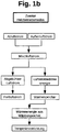
- ein Blockschema eines zweiten Heizbetriebsmodus des erfindungsgemäßen Verfahrens
- Fig. 1c
- ein Blockschema eines ersten Kühlbetriebsmodus des erfindungsgemäßen Verfahrens
- Fig. 1d
- ein Blockschema eines zweiten Kühlbetriebsmodus des erfindungsgemäßen Verfahrens
- Fig. 2
- eine Ausführung einer Vorrichtung zur Durchführung des erfindungsgemäßen Verfahrens
- Das erfindungsgemäße Verfahren umfasst sechs Betriebsarten - einen ersten Heizbetriebsmodus, einen zweiten Heizbetriebsmodus, einen ersten Kühlbetriebsmodus, einen zweiten Kühlbetriebsmodus, einen Komfortmodus und einen Energiesparmodus.
-
Fig. 1a zeigt ein Blockschema des ersten Heizbetriebsmodus. In diesem ersten Heizbetriebsmodus wird Luftstromwärmenergie eines Abluftstroms eines Gebäudes auf einen Wärmespeicher übertragen und dieser Abluftstrom anschließend als Fortluftstrom abgeführt. Im Bedarfsfall wird dann Wärmeenergie vom Wärmespeicher als Gebäudewärmeenergie an das Gebäude übertragen. - In
Fig. 1b ist ein Blockschema des erstes Kühlbetriebsmodus gezeigt. Dieser zeichnet sich dadurch aus, dass Wärmeenergie aus einem Kältespeicher auf einen Abluftstrom übertragen und dieser Abluftstrom anschließend als Fortluftstrom abgeführt wird. Hier wird im Bedarfsfall Gebäudewärmeenergie des Gebäudes auf den Kältespeicher übertragen. - In dem zweiten Heizbetriebsmodus (siehe Blockschema in
Fig. 1c ) wird ein Abluftstrom des Gebäudes mit einem Außenluftstrom zu einem Mischluftstrom gemischt und Luftstromwärmeenergie dieses Mischluftstroms in einen Wärmespeicher überführt. Anschließend wird der Mischluftstrom als Fortluftstrom abgeführt. Im Bedarfsfall wird dann Wärmeenergie vom Wärmespeicher als Gebäudewärmeenergie an das Gebäude übertragen. - Der im Blockschema in
Fig. 1d dargestellte zweite Kühlbetriebsmodus zeichnet sich dadurch aus, dass ein Abluftstrom des Gebäudes mit einem Außenluftstrom zu einem Mischluftstrom gemischt und Wärmeenergie aus einem Kältespeicher auf diesen Mischluftstrom übertragen wird, wobei anschließend der Mischluftstrom als Fortluftstrom abgeführt wird. Im Bedarfsfall wird Gebäudewärmeenergie aus dem Gebäude auf den Kältespeicher übertragen. - Ein Umschalten zwischen diesen Betriebsmodi kann dabei beispielsweise mit üblicher Steuer- und Regeltechnik erfolgen, wobei als Steuer- bzw. Regelgrößen insbesondere die Temperaturen der Abluft und der Außenluft sowie eine gewünschte Gebäudelufttemperatur genutzt werden können. Ebenso kann eine Kombination aus Temperatur und Feuchtigkeit der Abluft und/oder Außenluft als Steuer- und Regelgröße dienen.
- Sowohl im ersten Heizbetriebsmodus, als auch im zweiten Heizbetriebsmodus kann die Gebäudewärmeenergie auf einen Zuluftstrom des Gebäudes übertragen werden. Ebenso können im ersten Kühlbetriebsmodus und im zweiten Kühlbetriebsmodus Zuluftwärmeenergie eines Zuluftstroms des Gebäudes auf den Kältespeicher übertragen werden. Allerdings ist dies nicht zwingend. Es ist beispielsweise ebenso möglich, die Gebäudewärmeenergie direkt an bereits im Gebäude befindliche Gebäudeluft bzw. die Wärmeenergie der bereits im Gebäude befindlichen Gebäudeluft an den Kältspeicher zu übertragen. Selbstverständlich können diese Ausführungen aber auch miteinander kombiniert werden.
- Bei dem Komfortmodus wird alternierend Luftstromwärmeenergie von einem Abluftstrom des Gebäudes auf einen Wärmespeicher und Wärmeenergie eines Kältespeichers auf den Abluftstrom übertragen. Anschließend wird dieser Abluftstrom als Fortluftstrom abgeführt. Im Bedarfsfall können dann Wärmeenergie aus dem Wärmespeicher als Gebäudewärmeenergie dem Gebäude zugeführt und/oder Gebäudewärmeenergie dem Kältespeicher zugeführt werden. In diesem Komfortmodus wird in einer Variante dem Abluftstrom vor der Übertragung der Luftstromwärmeenergie auf den Wärmespeicher bzw. vor der Übertragung der Wärmeenergie des Kältespeichers auf den Abluftstrom ein Außenluftstrom beigemischt, wobei dieser Außenluftstrom anschließend zusammen mit dem Abluftstrom als Fortluftstrom abgeführt wird.
- In dem Energiesparmodus wird der Abluftstrom direkt als Fortluftstrom abgeführt. Eine Übertragung von Wärmeenergie des Abluftstroms auf den Wärmespeicher bzw. von Wärmeenergie aus dem Kältespeicher auf den Abluftstrom ist hier nicht vorgesehen.
- Bei dem zweiten Kühlbetriebsmodus, dem zweiten Heizbetriebsmodus sowie dem Komfortmodus können beim Mischen des Abluftstroms mit dem Außenluftstrom die Anteile des Abluftstroms und des Außenluftstroms variiert werden. Eine Regelung des Mischungsverhältnisses zwischen Abluftstrommenge und Außenluftstrommenge kann dabei beispielsweise anhand des Temperaturunterschieds zwischen Abluft und Außenluft erfolgen.
- Als weiterer Betriebsmodus kann das erfindungsgemäße Verfahren einen Brandmodus aufweisen. Bei diesem Brandmodus wird ein Rauchgase führender Abluftstrom des Gebäudes direkt an die Außenluft abgeführt.
- In
Fig. 2 ist eine Vorrichtung zur Durchführung des erfindungsgemäßen Verfahrens für die Klimatisierung eines Gebäudes dargestellt. Diese Vorrichtung weist einen ersten Pufferspeicher 1, einen zweiten Pufferspeicher 2, eine reversibel arbeitende Wärmepumpenanordnung 3 und einen Luft-Flüssigkeit-Wärmetauscher 4 auf. Der Luft-Flüssigkeit-Wärmetauscher 4 ist von einem Wärmetauschergehäuse 5 umgeben, wobei dieses Wärmetauschergehäuse 5 einen Abluftstromanschluss 6, einen Fortluftstromanschluss 7, einen ersten Kühlmittelanschluss 8 der Wärmepumpenanordnung 3, einen zweiten Kühlmittelanschluss 9 der Wärmepumpenanordnung 3 und einen Außenluftanschluss 10 aufweist. Innerhalb des Wärmetauschergehäuses 5 ist eine erste Bypassanordnung 11 und eine zweite Bypassanordnung 12 angeordnet, wobei die zweite Bypassanordnung 12 eine den Außenluftanschluss 10 regelbare Verschlusseinrichtung ist. In der dargestellten Ausführung ist die Verschlusseinrichtung als eine Verschlussklappe ausgebildet, die einen Querschnitt des Außenluftanschlusses 10 verengen kann. Mit dieser zweiten Bypassanordnung 12 kann einem am Abluftstromanschluss 6 eintretenden Abluftstrom ein über den Außenluftanschluss 10 eintretender Außenluftstrom beigemischt werden, wobei mithilfe der Verschlusseinrichtung das Mischungsverhältniss zwischen Abluft und Außenluft eingestellt werden kann. Im Extremfall schließt die Verschlusseinrichtung den Außenluftanschluss 10 vollständig, sodass der Abluft keine Außenluft beigemischt wird. - Ein erster Kühlmittelkreislauf wird von einem Verdichter und einer Drossel der Wärmepumpenanordnung 3, dem Luft-Flüssigkeit-Wärmetauscher 4 und einem ersten Flüssigkeit-Flüssigkeit-Wärmetauscher 13 im ersten Pufferspeicher 1 über entsprechende Zu- und Ablaufleitungen gebildet. Ein zweiter Kühlmittelkreislauf erfolgt über den Verdichter, die Drossel, den Luft-Flüssigkeit-Wärmetauscher 4 und einen zweiten Flüssigkeit-Flüssigkeit-Wärmetauscher 14 in dem zweiten Pufferspeicher 2. Die Flüssigkeit-Flüssigkeit-Wärmetauscher 13, 14 in den beiden Pufferspeichern 1, 2 und der Luft-Flüssigkeit-Wärmetauscher sind im Sinne der reversiblen Wärmepumpenanordnung 3 sowohl als Verdampfer, als auch als Kondensator betreibbar. Die Wärmepumpenanordnung 3 ist dabei so ausgebildet, dass diese mit einer Umschaltvorrichtung zwischen dem ersten Kühlmittelkreislauf und dem zweiten Kühlmittelkreislauf umschaltbar ist. Beide Pufferspeicher 1, 2 sind sowohl als Wärmespeicher, als auch als Kältespeicher betreibbar. Der Verdichter, die Drossel und die Umschaltvorrichtung sind in der dargestellten Ausführung in einem Wärmepumpengehäuse 15 untergebracht und nicht sichtbar.
- Der Luft-Flüssigkeit-Wärmetauscher 4 ist so innerhalb des Wärmetauschergehäuses 5 angeordnet, dass der Abluftstrom über diesen Luft-Flüssigkeit-Wärmetauscher 4 geführt und als Fortluftstrom über den Fortluftstromanschluss 7 aus dem Wärmetauschergehäuses 5 herausgeführt werden kann. Der Abluftstrom wird dabei mit einem im Wärmetauschergehäuse 5 angeordneten Ventilator 16 vom Abluftstromanschluss 6 zum Fortluftstromanschluss 7 geführt. Der Ventilator 16 muss allerdings nicht zwingend im Wärmetauschergehäuse 5 angeordnet sein. Ebenso kann dieser beispielsweise auch am Fortluftstromanschluss 7 angebracht sein. Vor dem Luft-Flüssigkeit-Wärmetauscher 4 ist ein Luftfilter 17 angeordnet, der die Abluft vor dem Durchströmen des Luft-Flüssigkeit-Wärmetauscher 4 reinigt.
- Weiterhin kann die Abluft über die erste Bypassanordnung 11 auch am Luft-Flüssigkeit-Wärmetauscher 4 vorbeigeführt und direkt als Fortluftstrom über der Fortluftstromanschluss 7 aus dem Wärmetauschergehäuse 5 herausgeführt werden. Hierzu ist die erste Bypassanordnung 11 im Wärmetauschergehäuse 5 als Bypasskanal ausgebildet, der von einem regelbaren Verschlusselement 18 verschließbar ist. Das Verschlusselement 18 ist in der dargestellten Variante als eine Klappe ausgebildet, ohne dass das Verschlusselement 18 hierauf beschränkt ist.
- Der erste und der zweite Pufferspeicher 1, 2 sind mit einer Temperiervorrichtung 19 des Gebäudes verbunden. Hierfür sind an beiden Pufferspeichern Anschlüsse für die Temperiervorrichtung 19 vorgesehen. Die Temperiervorrichtung 19 kann dabei ein Umluftgerät oder ein Bodeneinbaugerät oder ein Heiz-Kühldeckensegel oder eine Wandtemperiervorrichtung oder eine Fußbodentemperiervorrichtung oder eine Kombination aus diesen ist. Zur Wärmeübertragung zwischen der Temperiervorrichtung 19 und den Pufferspeicher 1, 2 kann ein in den Pufferspeichern 1, 2 befindliches Wärmeträgermedium direkt an die Temperiervorrichtung 19 übertragen werden. Ebenso können die Temperiervorrichtung 19 und die Pufferspeicher 1, 2 auch über weitere Kühlmittelkreisläufe 20, 21 miteinander verbunden, wobei dann in den Pufferspeichern 1, 2 weitere Wärmetauscher 22, 23 angeordnet sind, die die Wärme vom Wärmeträgermedium der Pufferspeicher 1, 2 auf ein Kühlmittel dieser Kühlmittelkreisläufe 20, 21 übertragen.
- In der dargestellten Ausführung sind der Verdichter und die Drossel der Wärmepumpenanordnung 3 außerhalb des Wärmetauschergehäuses 5 angeordnet. Ebenso können diese aber auch innerhalb des Wärmetauschergehäuses 5 angeordnet sein können.
- Die oben aufgeführten Betriebsmodi sind mit dieser Vorrichtung dabei wie folgt realisierbar. Für den ersten Heizbetriebsmodus wird der Abluftstrom des Gebäudes über den Abluftstromanschluss 6 in das Wärmetauschergehäuse 5 hineingeführt. Die erste und die zweite Bypassanordnung 11, 12 sind geschlossen. Damit wird der Abluftstrom vom Ventilator 16 durch den Luftfilter 17 und anschließend durch den Luft-Flüssigkeit-Wärmetauscher 4 geführt. Am Luft-Flüssigkeit-Wärmetauscher 4 wird die Luftstromwärmeenergie auf einen der beiden Kühlmittelkreisläufe übertragen. Dabei wird der Abluftstrom abgekühlt und anschließend als Fortluftstrom über den Fortlustromanschluss 7 aus dem Wärmetauschergehäuse 5 herausgeführt. Die auf den ersten bzw. zweiten Kühlmittelkreislauf übertragene Wärmeenergie wird dann auf den zugeordneten Pufferspeicher 1, 2 übertragen. Die Wärmepumpenanordnung 3 kann dabei so zwischen den beiden Kühlmittelkreisläufen hin und her geschaltet werden, dass die Wärmeenergie auf beide Pufferspeicher 1, 2 übertragen wird. Ebenso kann die Wärmeenergie aber auch nur auf einen der beiden Pufferspeicher 1, 2 übertragen werden oder erst ein Pufferspeicher 1 vollständig und anschließend der andere Pufferspeicher 2 beladen werden. Im ersten Heizbetriebsmodus arbeiten beide bzw. einer der beiden Pufferspeicher 1, 2 als Wärmespeicher. Im Bedarfsfall wird dann Wärmeenergie von einem der beiden Pufferspeicher 1, 2 bzw. von beiden Pufferspeichern 1, 2 als Gebäudewärmeenergie an die Temperiervorrichtung 19 im Gebäude übertragen.
- Für den zweiten Heizbetriebsmodus wird nun ausgehend vom ersten Heizbetriebsmodus die Verschlusseinrichtung der zweiten Bypassanordnung 12 geöffnet, sodass der Abluft, bevor diese den Luft-Flüssigkeit-Wärmetauscher 4 erreicht, Außenluft beigemischt wird. Dieser Mischluftstrom aus Abluft und Außenluft wird dann analog zum Abluftstrom im ersten Heizbetriebsmodus vom Ventilator 16 über den Luftfilter 17 zum Luft-Flüssigkeit-Wärmetauscher 4 geführt, wo die mitgeführte Luftstromwärmeenergie wie zuvor beschrieben auf einen oder beide Pufferspeicher 1, 2 übertragen wird. Die erste Bypassanordnung 11 ist auch im zweiten Heizbetriebsmodus geschlossen.
- Zum Ausführen des ersten Kühlbetriebsmodus sind sowohl die erste, als auch die zweite Bypassanordnung 11, 12 in diesem Betriebsmodus geschlossen. Der Abluftstrom wird über den Abluftstromanschluss 6 in das Wärmetauschergehäuse 5 hineingeführt und von dem Ventilator 16 über den Luftfilter 17 zum Luft-Flüssigkeit-Wärmetauscher 4 gesaugt. Innerhalb des Luft-Flüssigkeit-Wärmetauscher 4 wird dann Wärmeenergie, die mit dem ersten oder dem zweiten Kühlmittelkreislauf vom ersten Pufferspeicher 1 bzw. vom zweiten Pufferspeicher 2 dem Luft-Flüssigkeit-Wärmetauscher 4 zugeführt wurde, an die Abluft übertragen. Die Abluft wird dabei erwärmt. Anschließend wird die Abluft vom Ventilator 16 zum Fortluftstromanschluss 7 und dann als Fortluft aus dem Wärmetauschergehäuse 5 herausgeführt. Damit werden der erste oder der zweite oder beide Pufferspeicher 1, 2 abgekühlt und stehen als Wärmesenke zur Verfügung. Im Bedarfsfall kann dann Gebäudewärmeenergie des Gebäudes über die Temperiervorrichtung 19 auf einen der oder die Pufferpeicher 1, 2 übertragen werden.
- Ausgehend vom ersten Kühlbetriebsmodus wird für den zweiten Kühlbetriebsmodus die Verschlusseinrichtung der zweiten Bypassanordnung 12 geöffnet. Damit wird dem Abluftstrom Außenluft beigemischt und dieses Gemisch als Mischluftstrom zum Luft-Flüssigkeit-Wärmetauscher 4 geführt, wobei wie im ersten Kühlbetriebsmodus hier Wärmeenergie von einem der beiden Pufferspeicher 1, 2 oder beiden Pufferspeichern 1, 2 auf den Mischluftstrom übertragen wird, sodass dieser erwärmt und dann als Fortluft über den Fortluftstromanschluss 7 aus dem Wärmetauschergehäuse 5 herausgeführt wird.
- Für den Energiesparmodus wird die als verschließbarer Kanal zwischen dem Abluftstromanschluss 6 und dem Fortluftstromanschluss 7 ausgebildete erste Bypassanordnung 11 geöffnet, sodass der Abluftstrom unter Umgehung des Luft-Flüssigkeit-Wärmetauscher 4 direkt als Fortluftstrom über den Fortluftstromanschluss 7 abgeführt wird.
- Der Komfortmodus kann über die Ausführung mit zwei Pufferspeichern 1, 2 erreicht werden. Hierfür werden der erste Pufferspeicher 1 als Wärmespeicher und der zweite Pufferspeicher 2 als Kältespeicher verwendet. Zur Übertragung von Wärmeenergie des Abluftstroms bzw. des Mischluftstroms auf den ersten Pufferspeicher 1 wird die Wärmepumpenanordnung 3 auf den ersten Kühlmittelkreislauf geschaltet. Zur Abführung von Wärmeenergie aus dem zweiten Pufferspeicher 2 wird die Wärmepumpenanordnung 3 auf den zweiten Kühlmittelkreislauf geschaltet, sodass die Wärmeenergie aus dem zweiten Pufferspeicher 2 über den Luft-Flüssigkeit-Wärmetauscher 4 auf den Abluft- bzw. Mischluftstrom transferiert wird.
- Die Temperiervorrichtung 19 besteht aus einzelnen (nicht dargestellten) Temperiereinheiten, wobei diese in einzelnen Räumen des Gebäudes angeordnet sind. Jede Temperiereinheit ist dabei jeweils mit dem ersten und dem zweiten Pufferspeicher 1, 2 verbunden. Die einzelnen Temperiereinheiten sind nicht gezeigt. Ein Zuluftstrom wird über ein zentrales Zuluftgerät dem Gebäude zugeführt und in Teilströme aufgeteilt, welche in die einzelnen Räume geleitet werden. In dem (nicht dargestellten) Zuluftgerät wird die Zuluft bereits vortemperiert. Die damit ebenfalls vortemperierten Teilströme werden nun in den Räumen über die darin angeordneten Temperiereinheiten geführt, wobei je nach Wunschtemperatur im jeweiligen Raum dessen Teilstrom gekühlt oder erwärmt werden kann. Damit ist die Zuluft raumweise individuell einstellbar. Grundsätzlich ist eine Vortemperierung des Zuluftstroms im Zuluftgerät aber nicht zwingend. Ebenso kann die Zuluft auch untemperiert in die Räume geleitet werden, wobei dann die Temperierung der Teilströme dann alleinig über die Temperiervorrichtung 19 erfolgt.
- Im Falle eines Brandes im Gebäude wird die Abluft auch Brandgase mitführen, die aus dem Gebäude heraus geführt werden müssen. Hierfür wird im Brandmodus die die Brandgase mitführende Abluft über den Abluftstromanschluss 6 in das Wärmetauschergehäuse 5 hineingeführt. Die Verschlusseinrichtung der zweiten Bypassanordnung 12 ist dann geöffnet, sodass der die Brandgase mitführende Abluftstrom über den Außenluftanschluss 10 aus dem Wärmetauschergehäuse 5 herausgeführt wird. Der Ventilator 16 ist dabei abgeschaltet und der erste Bypasskanal 11 ist verschlossen. Je nach Strömungsverhältnissen kann am Außenluftanschluss 10 ein weiterer Ventilator zum Abführen der Abluft vorgesehen sein.
- Das vorgeschlagene Verfahren und die vorgeschlagene Vorrichtung können neben der Klimatisierung von Gebäuden grundsätzlich auch zur Warmwasseraufbereitung eines Gebäudes genutzt werden. Hierfür ist die Temperiervorrichtung entsprechend für eine Warmwasseraufbereitung ausgelegt.
-
- 1
- Pufferspeicher
- 2
- Pufferspeicher
- 3
- Wärmepumpenanordnung
- 4
- Luft-Flüssigkeit-Wärmetauscher
- 5
- Wärmetauschergehäuse
- 6
- Abluftstromanschluss
- 7
- Fortluftstromanschluss
- 8
- Kühlmittelanschluss
- 9
- Kühlmittelanschluss
- 10
- Außenluftanschluss
- 11
- Bypasskanal
- 12
- Verschlusseinrichtung
- 13
- Flüssigkeit-Flüssigkeit-Wärmetauscher
- 14
- Flüssigkeit-Flüssigkeit-Wärmetauscher
- 15
- Wärmepumpengehäuse
- 16
- Ventilator
- 17
- Luftfilter
- 18
- Verschlusseinrichtung
- 19
- Temperiervorrichtung
- 20
- Kühlmittelkreislauf
- 21
- Kühlmittelkreislauf
- 22
- Wärmetauscher
- 23
- Wärmetauscher
Claims (18)
- Verfahren zur Klimatisierung eines Gebäudes, dadurch gekennzeichnet, dass in einem ersten Heizbetriebsmodus Luftstromwärmenergie eines Abluftstroms des Gebäudes auf einen Wärmespeicher übertragen wird und dieser Abluftstrom anschließend als Fortluftstrom abgeführt wird und im Bedarfsfall Wärmeenergie vom Wärmespeicher als Gebäudewärmeenergie an das Gebäude übertragen wird und dass in einem ersten Kühlbetriebsmodus Wärmeenergie aus einem Kältespeicher auf einen Abluftstrom des Gebäudes übertragen wird und dieser Abluftstrom anschließend als Fortluftstrom abgeführt wird und im Bedarfsfall Gebäudewärmeenergie des Gebäudes auf den Kältespeicher übertragen wird und dass in einem zweiten Heizbetriebsmodus ein Abluftstrom des Gebäudes mit einem Außenluftstrom zu einem Mischluftstrom gemischt und Luftstromwärmeenergie dieses Mischluftstroms in den Wärmespeicher überführt wird und der Mischluftstrom anschließend als Fortluftstrom abgeführt wird und im Bedarfsfall Wärmeenergie vom Wärmespeicher als Gebäudewärmeenergie an das Gebäude übertragen wird und dass in einem zweiten Kühlbetriebsmodus ein Abluftstrom des Gebäudes mit einem Außenluftstrom zu einem Mischluftstrom gemischt und Wärmeenergie aus dem Kältespeicher auf diesen Mischluftstrom übertragen wird und der Mischluftstrom anschließend als Fortluftstrom abgeführt wird und im Bedarfsfall Gebäudewärmeenergie aus dem Gebäude auf den Kältespeicher übertragen wird und dass in einem Komfortmodus alternierend Luftstromwärmeenergie von einem Abluftstrom des Gebäudes auf einen Wärmespeicher und Wärmeenergie eines Kältespeichers auf den Abluftstrom übertragen werden und dieser Abluftstrom als Fortluftstrom abgeführt wird und im Bedarfsfall Wärmeenergie aus dem Wärmespeicher als Gebäudewärmeenergie dem Gebäude zugeführt und/oder Gebäudewärmeenergie aus dem Gebäude dem Kältespeicher zugeführt werden und dass in einem Energiesparmodus der Abluftstrom direkt als Fortluftstrom abgeführt wird.
- Verfahren nach Anspruch 1, dadurch gekennzeichnet, dass dem Abluftstrom vor der Übertragung der Luftstromwärmeenergie auf den Wärmespeicher bzw. vor der Übertragung der Wärmeenergie des Kältespeichers auf den Abluftstrom ein Außenluftstrom beigemischt wird und dieser anschließend mit dem Abluftstrom als Fortluftstrom abgeführt wird.
- Verfahren nach Anspruch 1 oder 2, dadurch gekennzeichnet, dass beim Mischen des Abluftstroms mit dem Außenluftstrom die Anteile des Abluftstroms und des Außenluftstroms variiert werden.
- Verfahren nach Anspruch 1, dadurch gekennzeichnet, dass in einem Brandmodus ein Rauchgase führender Abluftstrom des Gebäudes an die Außenluft abgeführt wird.
- Verfahren nach Anspruch 1 oder 2, dadurch gekennzeichnet, dass dem Gebäude untemperierte oder temperierte Außenluft als Zuluftstrom zugeführt wird.
- Verfahren nach Anspruch 5, dadurch gekennzeichnet, dass im ersten Heizbetriebsmodus und im zweiten Heizbetriebsmodus zumindest ein Teil der Gebäudewärmeenergie aus dem Wärmespeicher auf den Zuluftstrom des Gebäudes übertragen wird.
- Verfahren nach Anspruch 5, dadurch gekennzeichnet, dass im ersten Kühlbetriebsmodus und im zweiten Kühlbetriebsmodus Zuluftwärmeenergie des Zuluftstroms des Gebäudes auf den Kältespeicher übertragen wird.
- Vorrichtung zur Klimatisierung eines Gebäudes, wobei die Vorrichtung einen ersten Pufferspeicher (1), einen zweiten Pufferspeicher (2), eine reversibel arbeitende Wärmepumpenanordnung (3), einen Luft-Flüssigkeit-Wärmetauscher (4), einen im ersten Pufferspeicher (1) angeordneten ersten Flüssigkeit-Flüssigkeit-Wärmetauscher (13) und einen im zweiten Pufferspeicher (2) angeordneten zweiten Flüssigkeit-Flüssigkeit-Wärmetauscher aufweist und dass die Wärmepumpenanordnung (3) umschaltbar einen ersten Kühlmittelkreislauf zwischen dem ersten Flüssigkeit-Flüssigkeit-Wärmetauscher (13) und dem Luft-Flüssigkeit-Wärmetauscher (4) und einen zweiten Kühlmittelkreislauf zwischen dem zweiten Flüssigkeit-Flüssigkeit-Wärmetauscher (14) und dem Luft-Flüssigkeit-Wärmetauscher (4) bildet und dass ein Abluftstrom des Gebäudes mit einer Umlenkvorrichtung durch den Luft-Flüssigkeit-Wärmetauscher (4) oder entlang einer den Luft-Flüssigkeit-Wärmetauscher (4) umgehenden ersten Bypassanordnung (11) führbar ist und dass ein Außenluftstrom über eine zweite Bypassanordnung (12) dem Abluftstrom beimischbar ist und dass der erste Pufferspeicher (1) und der zweite Pufferspeicher (2) mit einer Temperiervorrichtung (19) des Gebäudes verbunden sind und dass die beiden Pufferspeicher (1, 2) als Wärmespeicher und Kältespeicher betreibbar sind und dass die Temperiervorrichtung (19) aus lokalen Temperiereinheiten besteht und dass diese Temperiereinheiten in einzelnen Räumen des Gebäudes angeordnet sind und dass die Temperiereinheiten jeweils mit dem ersten und dem zweiten Pufferspeicher (1, 2) verbunden sind.
- Vorrichtung nach Anspruch 8, dadurch gekennzeichnet, dass der Luft-Flüssigkeit-Wärmetauscher (4) von einem Wärmetauschergehäuse (5) umgeben ist und dass dieses Wärmetauschergehäuse (5) einen Abluftstromanschluss (6), einen Fortluftstromanschluss (7), einen ersten Kühlmittelanschluss (8) der Wärmepumpenanordnung (3), einen zweiten Kühlmittelanschluss (9) der Wärmepumpenanordnung (3) und einen Außenluftanschluss (10) aufweist und dass die zweite Bypassanordnung (12) als eine den Außenluftanschluss (10) regelbare Verschlusseinrichtung ausgebildet ist.
- Vorrichtung nach Anspruch 9, dadurch gekennzeichnet, dass die Verschlusseinrichtung eine Verschlussklappe ist und diese Verschlussklappe einen Querschnitt des Außenluftanschlusses (10) verengend ausgebildet ist.
- Vorrichtung nach Anspruch 9, dadurch gekennzeichnet, dass die erste Bypassanordnung (11) als ein in dem Wärmetauschergehäuse (4) angeordneter und verschließbarer Kanal zwischen dem Abluftstromanschluss (6) und dem Fortluftstromanschluss (7) ausgebildet ist.
- Vorrichtung nach Anspruch 9, dadurch gekennzeichnet, dass der Abluftstrom in einem in dem Wärmetauschergehäuse (5) angeordneten und den Luft-Flüssigkeit-Wärmetauscher (4) umgehenden Bypasskanal zum Außenluftanschluss (10) führbar ist.
- Vorrichtung nach Anspruch 8, dadurch gekennzeichnet, dass die Temperiervorrichtung (19) ein Umluftgerät oder ein Bodeneinbaugerät oder ein Heiz-Kühldeckensegel oder eine Wandtemperiervorrichtung oder eine Fußbodentemperiervorrichtung oder eine Kombination aus diesen ist.
- Vorrichtung nach Anspruch 8, dadurch gekennzeichnet, dass die Temperiervorrichtung (19) in einem Zuluftstrom des Gebäudes angeordnet ist.
- Vorrichtung nach Anspruch 8, dadurch gekennzeichnet, dass ein Zuluftstrom über einen Außenluftdurchlass oder über ein Zuluftgerät dem Gebäude zuführbar ist und dass im Falle des Zuluftgerätes ein den Zuluftstrom temperierender Luft-Flüssigkeit-Wärmetauscher des Zuluftgerätes über einen weiteren Flüssigkeitskreislauf mit dem ersten und/oder dem zweiten Pufferspeicher (1, 2) verbunden ist.
- Vorrichtung nach Anspruch 8, dadurch gekennzeichnet, dass die Temperiereinheiten in Teilströmen des Zuluftstroms angeordnet sind.
- Vorrichtung nach Anspruch 9, dadurch gekennzeichnet, dass ein Verdichter und eine Drossel der Wärmepumpenanordnung (3) außerhalb oder innerhalb des Wärmetauschergehäuses (5) angeordnet sind.
- Vorrichtung nach Anspruch 8, 9 oder 15, dadurch gekennzeichnet, dass das Wärmetauschergehäuse und/oder die Wärmepumpenanordnung und/oder das Zuluftgerät und/oder die Pufferspeicher in einem Gehäuse angeordnet.
Applications Claiming Priority (1)
| Application Number | Priority Date | Filing Date | Title |
|---|---|---|---|
| DE102017006460.1A DE102017006460A1 (de) | 2017-07-07 | 2017-07-07 | Verfahren zur Klimatisierung eines Gebäudes und eine Vorrichtung zur Durchführung des Verfahrens |
Publications (3)
| Publication Number | Publication Date |
|---|---|
| EP3425300A2 true EP3425300A2 (de) | 2019-01-09 |
| EP3425300A3 EP3425300A3 (de) | 2019-01-16 |
| EP3425300B1 EP3425300B1 (de) | 2022-11-02 |
Family
ID=62874543
Family Applications (1)
| Application Number | Title | Priority Date | Filing Date |
|---|---|---|---|
| EP18000574.6A Active EP3425300B1 (de) | 2017-07-07 | 2018-07-04 | Verfahren zur klimatisierung eines gebäudes und ein gebäude mit einer vorrichtung zur durchführung des verfahrens |
Country Status (6)
| Country | Link |
|---|---|
| EP (1) | EP3425300B1 (de) |
| DE (1) | DE102017006460A1 (de) |
| DK (1) | DK3425300T3 (de) |
| HU (1) | HUE060915T2 (de) |
| LT (1) | LT3425300T (de) |
| PL (1) | PL3425300T3 (de) |
Families Citing this family (1)
| Publication number | Priority date | Publication date | Assignee | Title |
|---|---|---|---|---|
| DE102024123284A1 (de) * | 2024-08-14 | 2026-02-19 | FRENGER SYSTEMEN BV Heiz- & Kühltechnik Gesellschaft mit beschränkter Haftung | Wärmetechnische anlage für zeitkritische gebäude |
Family Cites Families (11)
| Publication number | Priority date | Publication date | Assignee | Title |
|---|---|---|---|---|
| FR2395466A1 (fr) * | 1977-06-24 | 1979-01-19 | Cophoc Sa | Procede et installation pour chauffer ou climatiser selon les saisons des locaux frequentes de jour par de nombreuses personnes |
| DE19702903C2 (de) * | 1997-01-28 | 2000-08-24 | Stiebel Eltron Gmbh & Co Kg | Klimaanlage mit einer Wärmepumpe |
| DE19813157C2 (de) | 1998-03-19 | 2000-07-27 | Hansa Ventilatoren Masch | Raumlufttechnische Anlage zur bivalenten Klimatisierung eines Raumes |
| DE19812775C2 (de) * | 1998-03-24 | 2000-09-07 | Thomas Sippel | Verfahren zur Erzeugung von Nutzkälte und/oder Nutzwärme in Gebäuden sowie Anlage zur Durchführung dieses Verfahrens |
| DE102007041041B4 (de) * | 2007-08-29 | 2015-07-16 | Stiebel Eltron Gmbh & Co. Kg | System zum Lüften/Heizen von Räumen |
| BE1019836A3 (nl) | 2011-02-22 | 2013-01-08 | Aeropulmo Bv Met Beperkte Aansprakelijkheid | Ventilatie-eenheid, werkwijze om een ventilatie-eenheid te vervaardigen en werkwijze om een woon- of verblijfsruimte te koelen. |
| SE1250068A1 (sv) * | 2012-01-31 | 2013-08-01 | Swegon Ab | System för styrning av inomhusklimatet i en byggnad |
| WO2015015244A1 (de) | 2013-07-29 | 2015-02-05 | Jan Franck | Temperatur-management-system |
| DE102014000232A1 (de) | 2014-01-09 | 2015-07-09 | Bertram Pelka | Variables regeneratives Energiesystem zum Heizen und Kühlen |
| GB2524551A (en) * | 2014-03-27 | 2015-09-30 | Mugur Ciprian Balan | Heating and cooling system for passive buildings based on heat and cold storage |
| DE202014106278U1 (de) * | 2014-11-27 | 2015-10-28 | Heinz-Dieter Hombücher | Vorrichtung zur Regelung des Wärmeträger-Volumenstroms eines Kreislaufverbundsystems |
-
2017
- 2017-07-07 DE DE102017006460.1A patent/DE102017006460A1/de active Pending
-
2018
- 2018-07-04 DK DK18000574.6T patent/DK3425300T3/da active
- 2018-07-04 EP EP18000574.6A patent/EP3425300B1/de active Active
- 2018-07-04 LT LTEP18000574.6T patent/LT3425300T/lt unknown
- 2018-07-04 HU HUE18000574A patent/HUE060915T2/hu unknown
- 2018-07-04 PL PL18000574.6T patent/PL3425300T3/pl unknown
Also Published As
| Publication number | Publication date |
|---|---|
| DK3425300T3 (da) | 2023-02-06 |
| EP3425300A3 (de) | 2019-01-16 |
| LT3425300T (lt) | 2023-02-10 |
| HUE060915T2 (hu) | 2023-04-28 |
| PL3425300T3 (pl) | 2023-02-20 |
| EP3425300B1 (de) | 2022-11-02 |
| DE102017006460A1 (de) | 2019-01-10 |
Similar Documents
| Publication | Publication Date | Title |
|---|---|---|
| DE102017206180B4 (de) | Wärmepumpe für ein Fahrzeug | |
| EP1606564B1 (de) | Verfahren und vorrichtung zur energierückgewinnung | |
| DE102020115992A1 (de) | Integriertes wärmeverwaltungssystem | |
| DE112023001241T5 (de) | Fahrzeugwärmepumpensystem | |
| DE202017105111U1 (de) | Wärmegewinnungsanlage und Wärmetauschereinheit | |
| DE102016204069A1 (de) | Klimaanlagensystem für Fahrzeuge | |
| DE102020119653B3 (de) | System zur Klimatisierung von Innenräumen eines Gebäudes | |
| DE112018000713T5 (de) | Fahrzeugklimatisierungsvorrichtung | |
| DE102019213860A1 (de) | Klimatisierungssystem für ein Kraftfahrzeug | |
| DE102007039195B4 (de) | Anordnung zum Klimatisieren eines Fahrzeugs | |
| DE19851889C2 (de) | Verfahren zum Betreiben einer Luft/Wasser-Wärmepumpe mit Energierecycling und Vorrichtung zur Durchführung des Verfahrens | |
| DE102007063009B4 (de) | Verfahren zur Belüftung von Objekten und Vorrichtung zur Belüftung von Objekten, insbesondere raumlufttechnische Anlage | |
| DE102018211559A1 (de) | Fahrzeug mit einer Klimatisierungsvorrichtung zum Erwärmen oder Kühlen eines elektrischen Energiespeichers | |
| EP2337696B1 (de) | Klimatisierungsanordnung | |
| DE102005048660A1 (de) | Vorrichtung und Verfahren zur Regulierung der Temperatur der Fahrgastzelle eines Kraftfahrzeugs | |
| EP3895921B1 (de) | Heiz- und/oder klimaanlage mit verbesserter luftbehandlung und verfahren dazu | |
| DE102004049621A1 (de) | Klimagerät | |
| EP3425300B1 (de) | Verfahren zur klimatisierung eines gebäudes und ein gebäude mit einer vorrichtung zur durchführung des verfahrens | |
| DE102007016345A1 (de) | Lüftungsanlage mit einer Vorrichtung zum Heizen und/oder Kühlen von Gebäuden | |
| DE102008004348A1 (de) | Redundantes Klimasystem für Lokomotiven | |
| DE102018100814A1 (de) | Schleife für die Zirkulation eines Kühlfluids zur Aufbereitung der Luft aus dem Fahrgastraum eines Fahrzeugs | |
| DE102019207810B4 (de) | Wärmepumpensystem für ein Fahrzeug und Heiz-, Belüftungs- und Klimaanlagenmodul | |
| DE102021204520A1 (de) | Klimatisierungsvorrichtung für elektrofahrzeuge und klimatisierungssystem für elektrofahrzeuge mit dieser vorrichtung | |
| EP0907871A1 (de) | Klimagerät | |
| DE102020128629A1 (de) | Vorrichtung und Verfahren zum kombinierten Betrieb einer Wärmepumpe zur Erwärmung von Wasser und eines Lüftungssystems |
Legal Events
| Date | Code | Title | Description |
|---|---|---|---|
| PUAI | Public reference made under article 153(3) epc to a published international application that has entered the european phase |
Free format text: ORIGINAL CODE: 0009012 |
|
| STAA | Information on the status of an ep patent application or granted ep patent |
Free format text: STATUS: THE APPLICATION HAS BEEN PUBLISHED |
|
| PUAL | Search report despatched |
Free format text: ORIGINAL CODE: 0009013 |
|
| AK | Designated contracting states |
Kind code of ref document: A2 Designated state(s): AL AT BE BG CH CY CZ DE DK EE ES FI FR GB GR HR HU IE IS IT LI LT LU LV MC MK MT NL NO PL PT RO RS SE SI SK SM TR |
|
| AX | Request for extension of the european patent |
Extension state: BA ME |
|
| AK | Designated contracting states |
Kind code of ref document: A3 Designated state(s): AL AT BE BG CH CY CZ DE DK EE ES FI FR GB GR HR HU IE IS IT LI LT LU LV MC MK MT NL NO PL PT RO RS SE SI SK SM TR |
|
| AX | Request for extension of the european patent |
Extension state: BA ME |
|
| RIC1 | Information provided on ipc code assigned before grant |
Ipc: F24D 11/02 20060101ALI20181211BHEP Ipc: F24F 12/00 20060101AFI20181211BHEP |
|
| STAA | Information on the status of an ep patent application or granted ep patent |
Free format text: STATUS: REQUEST FOR EXAMINATION WAS MADE |
|
| 17P | Request for examination filed |
Effective date: 20190401 |
|
| RBV | Designated contracting states (corrected) |
Designated state(s): AL AT BE BG CH CY CZ DE DK EE ES FI FR GB GR HR HU IE IS IT LI LT LU LV MC MK MT NL NO PL PT RO RS SE SI SK SM TR |
|
| STAA | Information on the status of an ep patent application or granted ep patent |
Free format text: STATUS: EXAMINATION IS IN PROGRESS |
|
| 17Q | First examination report despatched |
Effective date: 20200914 |
|
| GRAP | Despatch of communication of intention to grant a patent |
Free format text: ORIGINAL CODE: EPIDOSNIGR1 |
|
| STAA | Information on the status of an ep patent application or granted ep patent |
Free format text: STATUS: GRANT OF PATENT IS INTENDED |
|
| INTG | Intention to grant announced |
Effective date: 20220530 |
|
| GRAS | Grant fee paid |
Free format text: ORIGINAL CODE: EPIDOSNIGR3 |
|
| GRAA | (expected) grant |
Free format text: ORIGINAL CODE: 0009210 |
|
| STAA | Information on the status of an ep patent application or granted ep patent |
Free format text: STATUS: THE PATENT HAS BEEN GRANTED |
|
| AK | Designated contracting states |
Kind code of ref document: B1 Designated state(s): AL AT BE BG CH CY CZ DE DK EE ES FI FR GB GR HR HU IE IS IT LI LT LU LV MC MK MT NL NO PL PT RO RS SE SI SK SM TR |
|
| REG | Reference to a national code |
Ref country code: GB Ref legal event code: FG4D Free format text: NOT ENGLISH |
|
| REG | Reference to a national code |
Ref country code: CH Ref legal event code: EP Ref country code: AT Ref legal event code: REF Ref document number: 1529006 Country of ref document: AT Kind code of ref document: T Effective date: 20221115 |
|
| REG | Reference to a national code |
Ref country code: DE Ref legal event code: R096 Ref document number: 502018010940 Country of ref document: DE |
|
| REG | Reference to a national code |
Ref country code: IE Ref legal event code: FG4D Free format text: LANGUAGE OF EP DOCUMENT: GERMAN |
|
| REG | Reference to a national code |
Ref country code: NL Ref legal event code: FP |
|
| REG | Reference to a national code |
Ref country code: DK Ref legal event code: T3 Effective date: 20230130 |
|
| REG | Reference to a national code |
Ref country code: SE Ref legal event code: TRGR |
|
| REG | Reference to a national code |
Ref country code: NO Ref legal event code: T2 Effective date: 20221102 |
|
| PG25 | Lapsed in a contracting state [announced via postgrant information from national office to epo] |
Ref country code: PT Free format text: LAPSE BECAUSE OF FAILURE TO SUBMIT A TRANSLATION OF THE DESCRIPTION OR TO PAY THE FEE WITHIN THE PRESCRIBED TIME-LIMIT Effective date: 20230302 Ref country code: FI Free format text: LAPSE BECAUSE OF FAILURE TO SUBMIT A TRANSLATION OF THE DESCRIPTION OR TO PAY THE FEE WITHIN THE PRESCRIBED TIME-LIMIT Effective date: 20221102 Ref country code: ES Free format text: LAPSE BECAUSE OF FAILURE TO SUBMIT A TRANSLATION OF THE DESCRIPTION OR TO PAY THE FEE WITHIN THE PRESCRIBED TIME-LIMIT Effective date: 20221102 |
|
| REG | Reference to a national code |
Ref country code: HU Ref legal event code: AG4A Ref document number: E060915 Country of ref document: HU |
|
| PG25 | Lapsed in a contracting state [announced via postgrant information from national office to epo] |
Ref country code: RS Free format text: LAPSE BECAUSE OF FAILURE TO SUBMIT A TRANSLATION OF THE DESCRIPTION OR TO PAY THE FEE WITHIN THE PRESCRIBED TIME-LIMIT Effective date: 20221102 Ref country code: LV Free format text: LAPSE BECAUSE OF FAILURE TO SUBMIT A TRANSLATION OF THE DESCRIPTION OR TO PAY THE FEE WITHIN THE PRESCRIBED TIME-LIMIT Effective date: 20221102 Ref country code: IS Free format text: LAPSE BECAUSE OF FAILURE TO SUBMIT A TRANSLATION OF THE DESCRIPTION OR TO PAY THE FEE WITHIN THE PRESCRIBED TIME-LIMIT Effective date: 20230302 Ref country code: HR Free format text: LAPSE BECAUSE OF FAILURE TO SUBMIT A TRANSLATION OF THE DESCRIPTION OR TO PAY THE FEE WITHIN THE PRESCRIBED TIME-LIMIT Effective date: 20221102 Ref country code: GR Free format text: LAPSE BECAUSE OF FAILURE TO SUBMIT A TRANSLATION OF THE DESCRIPTION OR TO PAY THE FEE WITHIN THE PRESCRIBED TIME-LIMIT Effective date: 20230203 |
|
| PG25 | Lapsed in a contracting state [announced via postgrant information from national office to epo] |
Ref country code: SM Free format text: LAPSE BECAUSE OF FAILURE TO SUBMIT A TRANSLATION OF THE DESCRIPTION OR TO PAY THE FEE WITHIN THE PRESCRIBED TIME-LIMIT Effective date: 20221102 Ref country code: RO Free format text: LAPSE BECAUSE OF FAILURE TO SUBMIT A TRANSLATION OF THE DESCRIPTION OR TO PAY THE FEE WITHIN THE PRESCRIBED TIME-LIMIT Effective date: 20221102 Ref country code: EE Free format text: LAPSE BECAUSE OF FAILURE TO SUBMIT A TRANSLATION OF THE DESCRIPTION OR TO PAY THE FEE WITHIN THE PRESCRIBED TIME-LIMIT Effective date: 20221102 Ref country code: CZ Free format text: LAPSE BECAUSE OF FAILURE TO SUBMIT A TRANSLATION OF THE DESCRIPTION OR TO PAY THE FEE WITHIN THE PRESCRIBED TIME-LIMIT Effective date: 20221102 |
|
| REG | Reference to a national code |
Ref country code: DE Ref legal event code: R097 Ref document number: 502018010940 Country of ref document: DE |
|
| PG25 | Lapsed in a contracting state [announced via postgrant information from national office to epo] |
Ref country code: SK Free format text: LAPSE BECAUSE OF FAILURE TO SUBMIT A TRANSLATION OF THE DESCRIPTION OR TO PAY THE FEE WITHIN THE PRESCRIBED TIME-LIMIT Effective date: 20221102 Ref country code: AL Free format text: LAPSE BECAUSE OF FAILURE TO SUBMIT A TRANSLATION OF THE DESCRIPTION OR TO PAY THE FEE WITHIN THE PRESCRIBED TIME-LIMIT Effective date: 20221102 |
|
| PLBE | No opposition filed within time limit |
Free format text: ORIGINAL CODE: 0009261 |
|
| STAA | Information on the status of an ep patent application or granted ep patent |
Free format text: STATUS: NO OPPOSITION FILED WITHIN TIME LIMIT |
|
| 26N | No opposition filed |
Effective date: 20230803 |
|
| PG25 | Lapsed in a contracting state [announced via postgrant information from national office to epo] |
Ref country code: SI Free format text: LAPSE BECAUSE OF FAILURE TO SUBMIT A TRANSLATION OF THE DESCRIPTION OR TO PAY THE FEE WITHIN THE PRESCRIBED TIME-LIMIT Effective date: 20221102 |
|
| PG25 | Lapsed in a contracting state [announced via postgrant information from national office to epo] |
Ref country code: MC Free format text: LAPSE BECAUSE OF FAILURE TO SUBMIT A TRANSLATION OF THE DESCRIPTION OR TO PAY THE FEE WITHIN THE PRESCRIBED TIME-LIMIT Effective date: 20221102 |
|
| PG25 | Lapsed in a contracting state [announced via postgrant information from national office to epo] |
Ref country code: MC Free format text: LAPSE BECAUSE OF FAILURE TO SUBMIT A TRANSLATION OF THE DESCRIPTION OR TO PAY THE FEE WITHIN THE PRESCRIBED TIME-LIMIT Effective date: 20221102 |
|
| PG25 | Lapsed in a contracting state [announced via postgrant information from national office to epo] |
Ref country code: LU Free format text: LAPSE BECAUSE OF NON-PAYMENT OF DUE FEES Effective date: 20230704 |
|
| PG25 | Lapsed in a contracting state [announced via postgrant information from national office to epo] |
Ref country code: LU Free format text: LAPSE BECAUSE OF NON-PAYMENT OF DUE FEES Effective date: 20230704 |
|
| PG25 | Lapsed in a contracting state [announced via postgrant information from national office to epo] |
Ref country code: BG Free format text: LAPSE BECAUSE OF FAILURE TO SUBMIT A TRANSLATION OF THE DESCRIPTION OR TO PAY THE FEE WITHIN THE PRESCRIBED TIME-LIMIT Effective date: 20221102 |
|
| PG25 | Lapsed in a contracting state [announced via postgrant information from national office to epo] |
Ref country code: BG Free format text: LAPSE BECAUSE OF FAILURE TO SUBMIT A TRANSLATION OF THE DESCRIPTION OR TO PAY THE FEE WITHIN THE PRESCRIBED TIME-LIMIT Effective date: 20221102 |
|
| PG25 | Lapsed in a contracting state [announced via postgrant information from national office to epo] |
Ref country code: CY Free format text: LAPSE BECAUSE OF FAILURE TO SUBMIT A TRANSLATION OF THE DESCRIPTION OR TO PAY THE FEE WITHIN THE PRESCRIBED TIME-LIMIT; INVALID AB INITIO Effective date: 20180704 |
|
| PGFP | Annual fee paid to national office [announced via postgrant information from national office to epo] |
Ref country code: HU Payment date: 20250730 Year of fee payment: 8 |
|
| PGFP | Annual fee paid to national office [announced via postgrant information from national office to epo] |
Ref country code: NL Payment date: 20250723 Year of fee payment: 8 |
|
| PGFP | Annual fee paid to national office [announced via postgrant information from national office to epo] |
Ref country code: DK Payment date: 20250723 Year of fee payment: 8 Ref country code: LT Payment date: 20250722 Year of fee payment: 8 Ref country code: DE Payment date: 20250815 Year of fee payment: 8 |
|
| PGFP | Annual fee paid to national office [announced via postgrant information from national office to epo] |
Ref country code: NO Payment date: 20250725 Year of fee payment: 8 |
|
| PGFP | Annual fee paid to national office [announced via postgrant information from national office to epo] |
Ref country code: PL Payment date: 20250725 Year of fee payment: 8 Ref country code: IT Payment date: 20250731 Year of fee payment: 8 |
|
| PGFP | Annual fee paid to national office [announced via postgrant information from national office to epo] |
Ref country code: BE Payment date: 20250722 Year of fee payment: 8 Ref country code: GB Payment date: 20250724 Year of fee payment: 8 |
|
| PGFP | Annual fee paid to national office [announced via postgrant information from national office to epo] |
Ref country code: FR Payment date: 20250723 Year of fee payment: 8 Ref country code: AT Payment date: 20250721 Year of fee payment: 8 |
|
| PGFP | Annual fee paid to national office [announced via postgrant information from national office to epo] |
Ref country code: CH Payment date: 20250801 Year of fee payment: 8 Ref country code: SE Payment date: 20250723 Year of fee payment: 8 |
|
| PGFP | Annual fee paid to national office [announced via postgrant information from national office to epo] |
Ref country code: IE Payment date: 20250724 Year of fee payment: 8 |
|
| PG25 | Lapsed in a contracting state [announced via postgrant information from national office to epo] |
Ref country code: TR Free format text: LAPSE BECAUSE OF FAILURE TO SUBMIT A TRANSLATION OF THE DESCRIPTION OR TO PAY THE FEE WITHIN THE PRESCRIBED TIME-LIMIT Effective date: 20221102 |